JP4072324B2 - Magnetic recording medium and method for manufacturing the same - Google Patents
Magnetic recording medium and method for manufacturing the same Download PDFInfo
- Publication number
- JP4072324B2 JP4072324B2 JP2001192190A JP2001192190A JP4072324B2 JP 4072324 B2 JP4072324 B2 JP 4072324B2 JP 2001192190 A JP2001192190 A JP 2001192190A JP 2001192190 A JP2001192190 A JP 2001192190A JP 4072324 B2 JP4072324 B2 JP 4072324B2
- Authority
- JP
- Japan
- Prior art keywords
- film
- magnetic
- alloy
- less
- forming
- Prior art date
- Legal status (The legal status is an assumption and is not a legal conclusion. Google has not performed a legal analysis and makes no representation as to the accuracy of the status listed.)
- Expired - Fee Related
Links
- 238000000034 method Methods 0.000 title description 8
- 238000004519 manufacturing process Methods 0.000 title description 7
- 229910045601 alloy Inorganic materials 0.000 claims description 34
- 239000000956 alloy Substances 0.000 claims description 34
- 229910052760 oxygen Inorganic materials 0.000 claims description 20
- QVGXLLKOCUKJST-UHFFFAOYSA-N atomic oxygen Chemical compound [O] QVGXLLKOCUKJST-UHFFFAOYSA-N 0.000 claims description 18
- 239000001301 oxygen Substances 0.000 claims description 18
- 239000000758 substrate Substances 0.000 claims description 13
- 229910019222 CoCrPt Inorganic materials 0.000 claims description 10
- 241000849798 Nita Species 0.000 claims description 5
- 229910052804 chromium Inorganic materials 0.000 claims description 4
- 239000013078 crystal Substances 0.000 description 25
- 229910000531 Co alloy Inorganic materials 0.000 description 10
- 230000000052 comparative effect Effects 0.000 description 10
- 230000005415 magnetization Effects 0.000 description 9
- 230000005347 demagnetization Effects 0.000 description 8
- 230000015572 biosynthetic process Effects 0.000 description 7
- 230000001681 protective effect Effects 0.000 description 7
- 239000007789 gas Substances 0.000 description 6
- OKTJSMMVPCPJKN-UHFFFAOYSA-N Carbon Chemical compound [C] OKTJSMMVPCPJKN-UHFFFAOYSA-N 0.000 description 5
- 238000002441 X-ray diffraction Methods 0.000 description 5
- 229910052799 carbon Inorganic materials 0.000 description 5
- 238000010438 heat treatment Methods 0.000 description 5
- 239000010410 layer Substances 0.000 description 5
- 230000003647 oxidation Effects 0.000 description 5
- 238000007254 oxidation reaction Methods 0.000 description 5
- 238000003860 storage Methods 0.000 description 5
- 230000000694 effects Effects 0.000 description 3
- 238000001004 secondary ion mass spectrometry Methods 0.000 description 3
- XKRFYHLGVUSROY-UHFFFAOYSA-N Argon Chemical compound [Ar] XKRFYHLGVUSROY-UHFFFAOYSA-N 0.000 description 2
- 229910000521 B alloy Inorganic materials 0.000 description 2
- 239000004721 Polyphenylene oxide Substances 0.000 description 2
- 229910001260 Pt alloy Inorganic materials 0.000 description 2
- 150000001875 compounds Chemical class 0.000 description 2
- 230000008878 coupling Effects 0.000 description 2
- 238000010168 coupling process Methods 0.000 description 2
- 238000005859 coupling reaction Methods 0.000 description 2
- 238000010586 diagram Methods 0.000 description 2
- 239000006185 dispersion Substances 0.000 description 2
- 239000011229 interlayer Substances 0.000 description 2
- 230000001050 lubricating effect Effects 0.000 description 2
- 239000000463 material Substances 0.000 description 2
- 230000001590 oxidative effect Effects 0.000 description 2
- 125000005010 perfluoroalkyl group Chemical group 0.000 description 2
- 229920000570 polyether Polymers 0.000 description 2
- 230000035945 sensitivity Effects 0.000 description 2
- 238000004544 sputter deposition Methods 0.000 description 2
- MYMOFIZGZYHOMD-UHFFFAOYSA-N Dioxygen Chemical compound O=O MYMOFIZGZYHOMD-UHFFFAOYSA-N 0.000 description 1
- 229910005805 NiNb Inorganic materials 0.000 description 1
- 229910001362 Ta alloys Inorganic materials 0.000 description 1
- 229910001069 Ti alloy Inorganic materials 0.000 description 1
- 229910000323 aluminium silicate Inorganic materials 0.000 description 1
- 238000004458 analytical method Methods 0.000 description 1
- 229910052786 argon Inorganic materials 0.000 description 1
- 230000005540 biological transmission Effects 0.000 description 1
- 230000015556 catabolic process Effects 0.000 description 1
- 230000007797 corrosion Effects 0.000 description 1
- 238000005260 corrosion Methods 0.000 description 1
- 230000007423 decrease Effects 0.000 description 1
- 238000006731 degradation reaction Methods 0.000 description 1
- 230000006866 deterioration Effects 0.000 description 1
- HNPSIPDUKPIQMN-UHFFFAOYSA-N dioxosilane;oxo(oxoalumanyloxy)alumane Chemical compound O=[Si]=O.O=[Al]O[Al]=O HNPSIPDUKPIQMN-UHFFFAOYSA-N 0.000 description 1
- 229910001882 dioxygen Inorganic materials 0.000 description 1
- 238000005516 engineering process Methods 0.000 description 1
- NBVXSUQYWXRMNV-UHFFFAOYSA-N fluoromethane Chemical compound FC NBVXSUQYWXRMNV-UHFFFAOYSA-N 0.000 description 1
- 238000005259 measurement Methods 0.000 description 1
- 238000002360 preparation method Methods 0.000 description 1
- 238000007670 refining Methods 0.000 description 1
- 229910052702 rhenium Inorganic materials 0.000 description 1
- 229910010271 silicon carbide Inorganic materials 0.000 description 1
- HBMJWWWQQXIZIP-UHFFFAOYSA-N silicon carbide Chemical compound [Si+]#[C-] HBMJWWWQQXIZIP-UHFFFAOYSA-N 0.000 description 1
- 239000005341 toughened glass Substances 0.000 description 1
- 238000013519 translation Methods 0.000 description 1
- 230000014616 translation Effects 0.000 description 1
- UONOETXJSWQNOL-UHFFFAOYSA-N tungsten carbide Chemical compound [W+]#[C-] UONOETXJSWQNOL-UHFFFAOYSA-N 0.000 description 1
- 229910052720 vanadium Inorganic materials 0.000 description 1
Images


Classifications
-
- G—PHYSICS
- G11—INFORMATION STORAGE
- G11B—INFORMATION STORAGE BASED ON RELATIVE MOVEMENT BETWEEN RECORD CARRIER AND TRANSDUCER
- G11B5/00—Recording by magnetisation or demagnetisation of a record carrier; Reproducing by magnetic means; Record carriers therefor
- G11B5/62—Record carriers characterised by the selection of the material
- G11B5/64—Record carriers characterised by the selection of the material comprising only the magnetic material without bonding agent
- G11B5/66—Record carriers characterised by the selection of the material comprising only the magnetic material without bonding agent the record carriers consisting of several layers
- G11B5/676—Record carriers characterised by the selection of the material comprising only the magnetic material without bonding agent the record carriers consisting of several layers having magnetic layers separated by a nonmagnetic layer, e.g. antiferromagnetic layer, Cu layer or coupling layer
-
- G—PHYSICS
- G11—INFORMATION STORAGE
- G11B—INFORMATION STORAGE BASED ON RELATIVE MOVEMENT BETWEEN RECORD CARRIER AND TRANSDUCER
- G11B5/00—Recording by magnetisation or demagnetisation of a record carrier; Reproducing by magnetic means; Record carriers therefor
- G11B5/62—Record carriers characterised by the selection of the material
- G11B5/64—Record carriers characterised by the selection of the material comprising only the magnetic material without bonding agent
- G11B5/66—Record carriers characterised by the selection of the material comprising only the magnetic material without bonding agent the record carriers consisting of several layers
- G11B5/672—Record carriers characterised by the selection of the material comprising only the magnetic material without bonding agent the record carriers consisting of several layers having different compositions in a plurality of magnetic layers, e.g. layer compositions having differing elemental components or differing proportions of elements
-
- G—PHYSICS
- G11—INFORMATION STORAGE
- G11B—INFORMATION STORAGE BASED ON RELATIVE MOVEMENT BETWEEN RECORD CARRIER AND TRANSDUCER
- G11B5/00—Recording by magnetisation or demagnetisation of a record carrier; Reproducing by magnetic means; Record carriers therefor
- G11B5/62—Record carriers characterised by the selection of the material
- G11B5/73—Base layers, i.e. all non-magnetic layers lying under a lowermost magnetic recording layer, e.g. including any non-magnetic layer in between a first magnetic recording layer and either an underlying substrate or a soft magnetic underlayer
- G11B5/7368—Non-polymeric layer under the lowermost magnetic recording layer
- G11B5/7369—Two or more non-magnetic underlayers, e.g. seed layers or barrier layers
-
- G—PHYSICS
- G11—INFORMATION STORAGE
- G11B—INFORMATION STORAGE BASED ON RELATIVE MOVEMENT BETWEEN RECORD CARRIER AND TRANSDUCER
- G11B5/00—Recording by magnetisation or demagnetisation of a record carrier; Reproducing by magnetic means; Record carriers therefor
- G11B5/84—Processes or apparatus specially adapted for manufacturing record carriers
-
- Y—GENERAL TAGGING OF NEW TECHNOLOGICAL DEVELOPMENTS; GENERAL TAGGING OF CROSS-SECTIONAL TECHNOLOGIES SPANNING OVER SEVERAL SECTIONS OF THE IPC; TECHNICAL SUBJECTS COVERED BY FORMER USPC CROSS-REFERENCE ART COLLECTIONS [XRACs] AND DIGESTS
- Y10—TECHNICAL SUBJECTS COVERED BY FORMER USPC
- Y10S—TECHNICAL SUBJECTS COVERED BY FORMER USPC CROSS-REFERENCE ART COLLECTIONS [XRACs] AND DIGESTS
- Y10S428/00—Stock material or miscellaneous articles
- Y10S428/90—Magnetic feature
-
- Y—GENERAL TAGGING OF NEW TECHNOLOGICAL DEVELOPMENTS; GENERAL TAGGING OF CROSS-SECTIONAL TECHNOLOGIES SPANNING OVER SEVERAL SECTIONS OF THE IPC; TECHNICAL SUBJECTS COVERED BY FORMER USPC CROSS-REFERENCE ART COLLECTIONS [XRACs] AND DIGESTS
- Y10—TECHNICAL SUBJECTS COVERED BY FORMER USPC
- Y10T—TECHNICAL SUBJECTS COVERED BY FORMER US CLASSIFICATION
- Y10T428/00—Stock material or miscellaneous articles
- Y10T428/12—All metal or with adjacent metals
- Y10T428/12465—All metal or with adjacent metals having magnetic properties, or preformed fiber orientation coordinate with shape
-
- Y—GENERAL TAGGING OF NEW TECHNOLOGICAL DEVELOPMENTS; GENERAL TAGGING OF CROSS-SECTIONAL TECHNOLOGIES SPANNING OVER SEVERAL SECTIONS OF THE IPC; TECHNICAL SUBJECTS COVERED BY FORMER USPC CROSS-REFERENCE ART COLLECTIONS [XRACs] AND DIGESTS
- Y10—TECHNICAL SUBJECTS COVERED BY FORMER USPC
- Y10T—TECHNICAL SUBJECTS COVERED BY FORMER US CLASSIFICATION
- Y10T428/00—Stock material or miscellaneous articles
- Y10T428/12—All metal or with adjacent metals
- Y10T428/12493—Composite; i.e., plural, adjacent, spatially distinct metal components [e.g., layers, joint, etc.]
- Y10T428/12771—Transition metal-base component
- Y10T428/12861—Group VIII or IB metal-base component
- Y10T428/12931—Co-, Fe-, or Ni-base components, alternative to each other
-
- Y—GENERAL TAGGING OF NEW TECHNOLOGICAL DEVELOPMENTS; GENERAL TAGGING OF CROSS-SECTIONAL TECHNOLOGIES SPANNING OVER SEVERAL SECTIONS OF THE IPC; TECHNICAL SUBJECTS COVERED BY FORMER USPC CROSS-REFERENCE ART COLLECTIONS [XRACs] AND DIGESTS
- Y10—TECHNICAL SUBJECTS COVERED BY FORMER USPC
- Y10T—TECHNICAL SUBJECTS COVERED BY FORMER US CLASSIFICATION
- Y10T428/00—Stock material or miscellaneous articles
- Y10T428/26—Web or sheet containing structurally defined element or component, the element or component having a specified physical dimension
- Y10T428/263—Coating layer not in excess of 5 mils thick or equivalent
- Y10T428/264—Up to 3 mils
- Y10T428/265—1 mil or less
Landscapes
- Magnetic Record Carriers (AREA)
- Manufacturing Of Magnetic Record Carriers (AREA)
Description
【0001】
【発明の属する技術分野】
本発明は、情報格納装置の磁気記録媒体に係わり、特に、高い記録密度を実現するのに好適な磁気記録媒体及びその製造方法に関する。
【0002】
【従来の技術】
情報化社会の進行により、日常的に扱う情報量は増加の一途を辿っている。これに伴って、磁気記憶装置に対する高記録密度・大記憶容量化の要求は留まるところを知らない。
現在、実用化されている磁気記録媒体では、磁性膜としてCo-Cr-Pt-B、Co-Cr-Pt-Ta等、Coを主成分とする合金が用いられている。これらのCo合金はc軸方向を磁化容易軸とする六方晶構造(hcp構造)をとるため、磁化を磁性膜面内で反転させて記録する面内磁気記録媒体としては、このCo合金のc軸が面内方向をとる結晶配向すなわち(11.0)配向が望ましい。しかし、この(11.0)配向は不安定であるため、基板上に直接Co合金を形成しても、一般にはこの配向とならない。
【0003】
そこで、体心立方構造(bcc構造)をとるCr(100)面がCo(11.0)面と整合性が良いことを利用して、このCo合金磁性膜を形成する前に、(100)配向したCr下地膜を形成し、その上にCo合金磁性膜をエピタキシャル成長させることによってCo合金磁性膜のc軸が面内方向を向いた(11.0)配向をとらせる手法が用いられている。
【0004】
また、Co合金磁性膜とCr下地膜界面での結晶格子整合性を更に向上させるために、Crに第二元素を添加し、Cr下地膜の格子間隔を増加させる手法が用いられている。
これによってCo合金磁性膜の(11.0)配向が更に増大し、保磁力を増加させることが出来る。このような技術の例としては、特開昭62-257618号公報や、特開昭63-197018号公報に示されているようにV、Ti等を添加するものが挙げられる。
【0005】
また、下地膜の下にNiTa膜又はNiNb膜を形成することで、Co合金磁性膜の(11.0)配向が得られ、高記録密度が達成できることが、特開平11-306532に示されている。更に、Co合金磁性膜の結晶粒を微細化し、かつ(11.0)配向を実現する手段として、第1の下地膜を一定の酸化雰囲気に曝した後に、第2の下地膜を形成する方法が、特表2000-503448、特開平10-143865に示されている。
【0006】
高記録密度化に必要な要素としては、記録媒体の高保磁力化と並んで低ノイズ化が挙げられる。
再生感度が極めて高いため高密度記録技術に適した磁気抵抗効果型ヘッドが用いられることが主流であるが、磁気抵抗効果型ヘッドを用いると、磁気記録媒体からの再生信号のみならず、ノイズに対する感度も同時に高くなる。このため、記録媒体には従来にも増して低ノイズ化が求められる。
【0007】
記録媒体のノイズを低減するためには、磁性膜中の結晶粒を微細化し、結晶粒径を均一化することなどが効果的であることが知られている。再公表WO98/06093では、磁性膜の結晶粒径を微細化するための下地膜としてCrTiB合金が有効であることが示されている。
【0008】
また、磁気記録媒体における重要な課題として、耐熱減磁特性の向上が挙げられる。熱減磁とは、磁気記録媒体からの再生出力が、経時的に減衰する現象である。媒体ノイズを低減するために、結晶粒を微細化したことで、個々の結晶粒の持つ磁化が熱的に不安定になるため熱減磁が起こると考えられている。
【0009】
この熱減磁の問題を解決するために特開2001-148110では、2つの磁気記録層を非磁性層を介して互いに反強磁性的に結合させる磁気記録媒体が提案されており、これをAF結合と呼んでいる。
【0010】
【発明が解決しようとする課題】
記録密度が、1平方ミリメートル当たり46.5メガビット(1平方インチ当たり30ギガビット)以上の磁気記憶装置を実現するためには、磁気特性、記録再生特性、及び実用上十分な耐熱減磁特性を有する磁気記録媒体を実現しなければならない。具体的には、結晶粒を微細化して低ノイズ化し、熱減磁を抑制するためのAF結合を用いた磁性膜とする必要があるが、更に、これらの媒体の特性を改善するには、六方晶構造を有しCo基合金から成る磁性膜の面内における結晶配向性を向上させることが効果的である。磁性膜結晶の膜面内の配向性を向上させれば、結晶磁気異方性が面内方向に強くなり、磁気特性の保磁力、保磁力角形比及び残留磁化が増加するため、記録再生特性が向上するからである。
【0011】
本発明では、六方晶構造を有しCo基合金から成る磁性膜の基板面に対し(11.0)配向性を向上させることを課題とした。この(11.0)配向性は、結晶粒の大きさがほぼ同じであればX線回折法による(11.0)回折強度が強い方が良好であり、また(11.0)回折ピークのロッキングカーブの半値幅が小さいほど、配向の分散が小さく配向性が高いと評価できる。
【0012】
【課題を解決するための手段】
強化ガラスその他の非磁性基板上に、非磁性かつアモルファス構造を有するNiTa合金から成る第1の下地膜、その上に少なくともCr及びTiを含む合金から成る第2の下地膜、その上にCoCrPt合金から成る第1の磁性膜、Ruから成る非磁性中間膜、CoCrPtB合金から成る第2の磁性膜が、順次、形成された磁気記録媒体において、第1の下地膜と第2の下地膜の界面を適度に酸化することで達成される。この酸素の存在はSIMS(二次イオン質量分析法)による深さプロファイルにおいて、酸素成分のピークとして観察できる。
【0013】
第1の磁性膜であるCoCrPt合金膜のPt濃度を略8at%以下にするのは、このCoCrPt合金膜の異方性磁界Hkを800kA/m以下にし、記録ヘッドが書き込み易くするためである。
【0014】
Pt濃度を略3%以上にするのは、第2の下地膜であるCrTi合金との格子整合を維持するためである。ここで第2の磁性膜であるCoCrPtB合金膜の(11.0)配向性を高めるためには、第2の下地膜であり体心立方構造を有するCrTi合金膜が(200)配向し、その上に第1の磁性膜であり六方晶構造を有するCoCrPt合金膜をエピタキシャル的に(11.0)配向させることが必要である。
【0015】
第1の磁性膜と第2の磁性膜の間には非磁性中間膜としてRuが形成されるが、このRu膜は第1及び第2の磁性膜と同様な六方晶構造であり、その膜厚が約0.5nmであって、Ruが数原子層しか形成されないので、結晶配向にはほとんど影響しない。
【0016】
CrTi合金膜の√2×aの長さとCoCrPt合金膜のcの長さは近い方が、第2の下地膜上に第1の磁性膜が結晶格子に歪みなく成長できるため、第1の磁性膜及び第2の磁性膜の(11.0)配向性が高くなる。第2の下地膜であるCrTi合金膜のTi濃度が略15at%より多いと、第2の磁性膜であるCoCrPt合金膜との格子定数のずれが大きくなるので結晶配向性が劣化する。
【0017】
一方、CrTi合金膜のTi濃度が略10at%より少ないとその結晶粒が大きくなりその上に形成する第1の磁性膜及び第2の磁性膜の結晶粒も大きくなるため、媒体ノイズが増大し好ましくない。
【0018】
下地膜の膜厚を薄くすると結晶粒が小さくなるため、記録再生時の媒体ノイズを低減できる。しかし一般に、下地膜を薄くすると磁性膜の(11.0)配向は劣化する傾向にあり、保磁力、残留磁化等が小さくなり再生出力が減少してしまう。本発明の実施例によれば、第2の下地膜の膜厚が5nm以上15nm以下の薄い領域でも、(11.0)回折ピークのロッキングカーブの半値幅は、ほぼ8°以下を維持できるため、再生出力を低下させずに媒体ノイズが低減できるのでS/Nが改善できる。ここで、この(11.0)回折ピークは第1の磁性膜によるピークと第2の磁性膜によるピークとが重なって単一のピークとして観察される。
【0019】
本発明の磁気記録媒体において、第1の下地膜と第2の下地膜の界面を適度に酸化するためには、第1下地膜を形成した後、その表面を微量な酸素ガスに曝し、第2下地膜を形成するまでの間に酸素分圧と該雰囲気に曝す時間の積(PO2・t)を、第2の下地膜がCrTiの場合は15(mPa・秒)以上35(mPa・秒)以下、第2の下地膜がCrTiBの場合は20(mPa・秒)以上40(mPa・秒)以下とする。
【0020】
更に、第2の磁性膜の上に磁性膜の保護膜としてカーボンを厚さ3nm以上5nm以下形成し、更に、吸着性のパーフルオロアルキルポリエーテルその他の潤滑膜を、厚さ1nm以上2nm以下設けることにより、信頼性が高く、高密度記録が可能な磁気記録媒体が得られる。
【0021】
また、保護膜として、水素を添加したカーボン膜、炭化シリコン、炭化タングステンその他の炭化化合物から成る膜、これらの化合物とカーボンの混合膜を用いることで、耐摺動性、耐食性を向上でき好ましい。
【0022】
上記の磁気記録媒体と、これを記録方向に駆動する駆動部と、記録部と再生部から成る磁気ヘッドと、この磁気ヘッドを上記磁気記録媒体に対して相対運動させる手段と、上記磁気ヘッドへの信号入力と該磁気ヘッドからの出力信号再生を行うための記録再生信号処理手段を有する磁気ディスク装置において、前記磁気ヘッドの再生部を磁気抵抗効果型磁気ヘッドで構成することにより、高記録密度における十分な信号強度を得ることができ、1平方ミリメートル当たり46.5メガビット以上の記録密度を持った信頼性の高い磁気ディスク装置を実現することが出来る。
【0023】
【発明の実施の形態】
<実施例1>
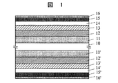
図1に、本発明の一実施の形態である、磁気記録媒体の膜構成を示す。
基板10には、2.5インチ型の化学強化されたアルミノシリケートを使用した。その上に、62at%Ni-38at%Ta合金からなる第1下地膜11、11'を厚さ30nm、85at%Cr-15at%Ti合金からなる第2下地膜12、12'を5nm、75at%Co-19at%Cr-6at%Pt合金からなる第1の磁性膜13、13'を4nm、Ruからなる非磁性中間膜14、14'を0.5nm、60at%Co-20at%Cr-14at%Pt-6at%Bからなる第2の磁性膜15、15'を15.5nm、更に、3.5nmのカーボン保護膜16、16'を形成した。
【0024】
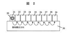
膜形成装置として、Intevac社製の枚葉式スパッタ装置mdp250Bを用い、タクト6.8秒で成膜した。各膜の形成時のアルゴン(Ar)ガス圧はすべて0.8Paとした。成膜中のメインチャンバ30(図2)の酸素分圧は約7×10のマイナス7乗(Pa)であった。このスパッタ装置のチャンバ構成は図2に示したとおりである。尚、仕込み室21には、基板20がセットされ、所定の成膜を終えて取り出し室29から取り出される。
【0025】
第1下地膜は基板を加熱しない状態で第1下地膜形成室22で形成し、加熱及び酸化室23でランプヒーターにより約250℃まで加熱しながら、99%Ar-1%O2混合ガスの圧力0.6Paの雰囲気に4秒間曝し、その後その上に上記各膜を第2の下地膜形成室24、第1の磁性膜形成室25、非磁性中間膜形成室26、第2の磁性膜形成室27、保護膜形成室28で順に形成した。このときのPO2・tは0.6Pa×0.01×4秒=24(mPa・秒)に相当する。上記カーボン保護膜まで形成した後、パーフルオロアルキルポリエーテル系の材料をフルオロカーボン材料で希釈したものを潤滑膜として厚さ1.8nm塗布した。
<実施例2>
上記実施例1とほぼ同様の膜構成及び作製方法で第2の磁気記録媒体を作製した。ただし次の点を変更した。上記第2の下地膜13、13'を82at%Cr-15at%Ti-3at%B合金とし、厚さを10nmとして作製した。また、上記99%Ar-1%O2混合ガスの圧力は0.8Paとした。このとき、PO2・tは32mPa・秒に相当する。
【0026】
図3に、実施例1及び実施例2において、99%Ar-1%O2混合ガスの圧力を変化させることにより、PO2・tを5(mPa・秒)以上43(mPa・秒)以下にして作製した磁気記録媒体における、第1及び第2の磁性膜の(11.0)配向性(Co(11.0)積分強度)の変化を示す。ここで、(11.0)配向性は、Cu-Kα線を用いてX線回折法により測定し、(11.0)回折ピークの積分強度により評価した。
【0027】
この第1及び第2の磁性膜の(11.0)回折ピークは重なり、単一のピークとして観察された。図3に示すように、第2の下地膜がCrTiの場合はPO2・tが15(mPa・秒)以上35(mPa・秒)以下、第2の下地膜がCrTiBの場合はPO2・tが20(mPa・秒)以上40(mPa・秒)以下の範囲でCo(11.0)積分強度が高く、(11.0)配向性が向上している。更に、その配向性の分散をロッキングカーブの半値幅で評価したところ、実施例1の媒体は6.8°、実施例2の媒体は7.8°であった。
【0028】
図4には、実施例1の媒体についてX線回折測定したときのX線回折プロファイルを示す。Co(11.0)回折が強い上記PO2・tの範囲では、磁性膜に対応した回折ピークは(11.0)のみであり、他の結晶面の回折ピークは見られない。また、実施例1の媒体において、SIMS分析により媒体の表面から深さ方向のプロファイルを評価したところ、第1の下地膜と第2の下地膜の界面付近に酸素のピークが観察された。しかし、透過電子顕微鏡により断面組織を観察したところ、上記第1の下地膜と第2の下地膜の界面にはこの酸素による新たな層は明瞭には見られなかった。酸素は局所的に散在しているものと推定される。
【0029】
図5には、図3に示した磁気記録媒体に対して、記録再生特性におけるS/Nを評価した結果を示す。ここでS/Nは、面記録密度としては1平方ミリメートル当たり51メガビット(線記録密度595kBPI、トラック密度55kTPI)の磁気ディスク装置条件において、孤立波再生出力の振幅S(Peak to Peak)と1mm当り25000回の磁化反転(25000fr/mm)の線記録密度における媒体ノイズNの比である。
【0030】
図3で実施例1及び実施例2の媒体においてCo(11.0)積分強度が強くなるPO2・tの範囲でS/Nも高くなり、実施例1の媒体では1平方ミリメートル当たり48メガビットの面記録密度の装置仕様を満足した。更に、実施例2の媒体では1平方ミリメートル当たり51メガビットの面記録密度の装置仕様を満足した。
<比較例1>
実施例1において、加熱及び酸化室23において99%Ar-1%O2混合ガスを供給しないこと以外は実施例1と同様の膜構成及び作製方法で比較例1の磁気記録媒体を製造した。
<比較例2>
実施例2において、加熱及び酸化室23において99%Ar-1%O2混合ガスを供給しないこと以外は実施例2と同様の膜構成及び作製方法で比較例2の磁気記録媒体を製造した。
<比較例3>
実施例2において、第2下地膜12、12'を77at%Cr-20at%Ti-3at%B合金とした以外は実施例2と同様の膜構成及び作製方法で比較例3の磁気記録媒体を製造した。
<実施例3>
実施例2において、上記第2の下地膜13、13'の厚さを15nmとし、上記第2の磁性膜15、15'の厚さを17nmにした以外は実施例2と同様の膜構成及び作製方法で実施例3の磁気記録媒体を製造した。
【0031】
実施例の媒体はすべて、第1の磁性膜と第2の磁性膜が非磁性中間層を介してAF結合しており、これはVSM(振動試料型磁力計)測定によるヒステリシスカーブの第1象限における段差によって確認された。いずれの実施例の媒体も段差の生じる磁界強度は40kA/m以上70kA/m以下であり、媒体としては比較的大きなAF結合磁界が働いている。
【0032】
以上の実施例及び比較例について、それぞれの磁気特性及び記録再生特性をまとめて表1に示す。
磁気特性は残留磁化曲線により測定し、Mrtは単位面積当たりの磁気モーメントであり、Hrは残留保磁力である。記録再生特性は、面記録密度としては1平方ミリメートル当たり51メガビット(線記録密度595kBPI、トラック密度55kTPI)の磁気ディスク装置条件において、孤立波再生出力の振幅S(Peak to Peak)と1mm当り25000回の磁化反転(25000fr/mm)における媒体ノイズNの比(S/N)と、12500fr/mmの磁化反転時における再生出力と孤立波再生出力の比(Re)で評価した。
【0033】
S/N及びReが共に大きいほど磁気ディスク装置の面記録密度を向上できる。実施例1及び2と比較例1及び2を比較すると、第1の下地膜と第2の下地膜の間に適度の酸素を供給することで、いずれの特性値も向上している。また、比較例3は適度の酸素を供給しているが、第2の下地膜のTi濃度が20at%と高いため、第1の磁性膜である75at%Co-19at%Cr-6at%Pt合金との格子整合性が悪くなりCo(11.0)の配向性が悪くなりMrt、S/Nが劣化している。熱減磁について実施例3の媒体で評価したところ、70℃で100時間放置してもビットエラーレートの劣化は0.5桁以下で良好であった。
【0034】
また、本発明の実施の態様に用いた膜形成装置に比べ、到達真空度が悪く酸素分圧が大きい膜形成装置、あるいは複数の基板に同時に膜形成できる装置の様に、第1下地膜形成後から第2下地膜を形成するまでの時間が長い膜形成装置では、上記実施例のように酸化室を特に設けなくても、上記のPO2・tの条件が満たされれば、上記実施例と同様の効果が得られる。
【0035】
【発明の効果】
本発明の磁気記録媒体は、熱減磁による再生信号の劣化が抑制され、かつ、従来より高いS/N比を有する。本発明の磁気記録媒体と磁気抵抗効果型ヘッドを用いることにより、1平方ミリメートル当たり46.5メガビット(1平方インチあたり30ギガビット)以上の記録密度を有する磁気記憶装置の実現が可能となる。
【0036】
【表1】

【図面の簡単な説明】
【図1】本発明の磁気記録媒体の断面構造の一例を示す模式図である。
【図2】磁気記録媒体の膜形成装置の一例を示す模式図である。
【図3】本発明の磁気記録媒体における磁性膜の結晶配向性を示す図である。
【図4】本発明の磁気記録媒体の一例と比較媒体のX線回折パターンである。
【図5】本発明の磁気記録媒体におけるS/Nを示す図である。
【符号の説明】
10...基板、 11、11'...第1下地膜、
12、12'...第2下地膜、 13、13'...第1の磁性膜、
14、14'...非磁性中間膜、 15、15'...第2の磁性膜、
16、16'...保護膜、 20...基板、
21...仕込み室、 22...第1の下地膜形成室
23...加熱及び酸化室、 24...第2の下地膜形成室、
25...第1の磁性膜形成室、 26...非磁性中間膜形成室、
27...第2の磁性膜形成室、 28...保護膜形成室、
29...取り出し室、 30...メインチャンバ。[0001]
BACKGROUND OF THE INVENTION
The present invention relates to a magnetic recording medium of an information storage device, and more particularly to a magnetic recording medium suitable for realizing a high recording density and a manufacturing method thereof.
[0002]
[Prior art]
With the progress of the information society, the amount of information handled on a daily basis is constantly increasing. As a result, the demand for higher recording density and larger storage capacity for magnetic storage devices remains unknown.
Currently, in magnetic recording media in practical use, alloys containing Co as a main component, such as Co—Cr—Pt—B and Co—Cr—Pt—Ta, are used as magnetic films. Since these Co alloys have a hexagonal crystal structure (hcp structure) with the c-axis direction as the easy axis of magnetization, the in-plane magnetic recording medium for recording by reversing the magnetization in the magnetic film plane is the c alloy of this Co alloy. A crystal orientation in which the axis is in an in-plane direction, that is, (11.0) orientation is desirable. However, since this (11.0) orientation is unstable, even if a Co alloy is formed directly on the substrate, this orientation is not generally achieved.
[0003]
Therefore, using the fact that the Cr (100) plane having a body-centered cubic structure (bcc structure) has good consistency with the Co (11.0) plane, before forming this Co alloy magnetic film, (100) A method is used in which an oriented Cr underlayer is formed, and a Co alloy magnetic film is epitaxially grown thereon to obtain a (11.0) orientation in which the c axis of the Co alloy magnetic film faces the in-plane direction. .
[0004]
In order to further improve the crystal lattice matching at the interface between the Co alloy magnetic film and the Cr underlayer, a method is used in which a second element is added to Cr to increase the lattice spacing of the Cr underlayer.
As a result, the (11.0) orientation of the Co alloy magnetic film is further increased, and the coercive force can be increased. Examples of such a technique include addition of V, Ti, etc. as disclosed in JP-A-62-257618 and JP-A-63-197018.
[0005]
Japanese Patent Laid-Open No. 11-306532 shows that by forming a NiTa film or NiNb film under the base film, the (11.0) orientation of the Co alloy magnetic film can be obtained and a high recording density can be achieved. Yes. Further, as a means for refining the crystal grains of the Co alloy magnetic film and realizing the (11.0) orientation, a method of forming the second base film after exposing the first base film to a certain oxidizing atmosphere Is disclosed in Japanese translations of PCT publication No. 2000-503448 and JP-A-10-143865.
[0006]
Factors necessary for increasing the recording density include reducing noise as well as increasing the coercivity of the recording medium.
The mainstream is the use of magnetoresistive heads that are suitable for high-density recording technology due to its extremely high read sensitivity. However, using magnetoresistive heads not only plays back signals from magnetic recording media but also noise. Sensitivity is also increased at the same time. For this reason, the recording medium is required to have lower noise than ever before.
[0007]
In order to reduce the noise of the recording medium, it is known that it is effective to make the crystal grains in the magnetic film fine and uniform the crystal grain diameter. Republished WO 98/06093 shows that a CrTiB alloy is effective as a base film for reducing the crystal grain size of a magnetic film.
[0008]
Further, an important problem in the magnetic recording medium is improvement of heat-resistant demagnetization characteristics. Thermal demagnetization is a phenomenon in which the reproduction output from a magnetic recording medium attenuates over time. It is thought that thermal demagnetization occurs because the magnetization of each crystal grain becomes thermally unstable due to the refinement of crystal grains in order to reduce medium noise.
[0009]
In order to solve this thermal demagnetization problem, Japanese Patent Laid-Open No. 2001-148110 proposes a magnetic recording medium in which two magnetic recording layers are antiferromagnetically coupled to each other via a nonmagnetic layer. This is called union.
[0010]
[Problems to be solved by the invention]
In order to realize a magnetic storage device having a recording density of 46.5 megabits per square millimeter (30 gigabits per square inch) or more, it has magnetic characteristics, recording / reproducing characteristics, and heat resistance demagnetization characteristics sufficient for practical use. A magnetic recording medium must be realized. Specifically, it is necessary to reduce the noise by reducing the crystal grains and to make a magnetic film using AF coupling for suppressing thermal demagnetization. Further, in order to improve the characteristics of these media, It is effective to improve the crystal orientation in the plane of a magnetic film having a hexagonal crystal structure and made of a Co-based alloy. If the in-plane orientation of the magnetic film crystal is improved, the magnetocrystalline anisotropy becomes stronger in the in-plane direction, and the coercive force, coercive force squareness ratio and remanent magnetization of the magnetic characteristics increase. This is because it improves.
[0011]
An object of the present invention is to improve the (11.0) orientation with respect to the substrate surface of a magnetic film having a hexagonal crystal structure and made of a Co-based alloy. This (11.0) orientation is better when the (11.0) diffraction intensity by the X-ray diffraction method is stronger if the crystal grain size is substantially the same, and the (11.0) diffraction peak It can be evaluated that the smaller the full width at half maximum of the rocking curve, the smaller the dispersion of orientation and the higher the orientation.
[0012]
[Means for Solving the Problems]
On a non-magnetic substrate such as tempered glass, a first base film made of a non-magnetic and amorphous NiTa alloy, a second base film made of an alloy containing at least Cr and Ti, and a CoCrPt alloy thereon In a magnetic recording medium in which a first magnetic film made of Ru, a nonmagnetic intermediate film made of Ru, and a second magnetic film made of CoCrPtB alloy are sequentially formed, the interface between the first base film and the second base film This is achieved by moderately oxidizing the. The presence of oxygen can be observed as a peak of an oxygen component in a depth profile by SIMS (secondary ion mass spectrometry).
[0013]
The reason why the Pt concentration of the CoCrPt alloy film, which is the first magnetic film, is set to about 8 at% or less is to make the anisotropic magnetic field Hk of the CoCrPt alloy film 800 kA / m or less so that the recording head can easily write.
[0014]
The reason why the Pt concentration is about 3% or more is to maintain lattice matching with the CrTi alloy as the second underlayer. Here, in order to improve the (11.0) orientation of the CoCrPtB alloy film as the second magnetic film, the CrTi alloy film having the body-centered cubic structure as the second underlayer is (200) oriented, The CoCrPt alloy film having the hexagonal crystal structure as the first magnetic film needs to be epitaxially (11.0) oriented.
[0015]
Ru is formed as a nonmagnetic intermediate film between the first magnetic film and the second magnetic film, and this Ru film has a hexagonal crystal structure similar to that of the first and second magnetic films. Since the thickness is about 0.5 nm and only a few atomic layers of Ru are formed, the crystal orientation is hardly affected.
[0016]
When the length of √2 × a of the CrTi alloy film is close to the length of c of the CoCrPt alloy film, the first magnetic film can grow on the second underlayer without distortion in the crystal lattice. The (11.0) orientation of the film and the second magnetic film is increased. When the Ti concentration of the CrTi alloy film as the second underlayer is higher than about 15 at%, the crystal constant is deteriorated because the lattice constant shift from the CoCrPt alloy film as the second magnetic film becomes large.
[0017]
On the other hand, if the Ti concentration of the CrTi alloy film is less than about 10 at%, the crystal grains increase and the crystal grains of the first magnetic film and the second magnetic film formed thereon also increase, so that the medium noise increases. It is not preferable.
[0018]
When the thickness of the underlying film is reduced, the crystal grains are reduced, so that medium noise during recording and reproduction can be reduced. However, in general, when the base film is thinned, the (11.0) orientation of the magnetic film tends to deteriorate, and the coercive force, the residual magnetization, etc. become small and the reproduction output decreases. According to the embodiment of the present invention, the half width of the rocking curve of the (11.0) diffraction peak can be maintained at about 8 ° or less even in the thin region where the film thickness of the second base film is 5 nm or more and 15 nm or less. Since the medium noise can be reduced without reducing the reproduction output, the S / N can be improved. Here, this (11.0) diffraction peak is observed as a single peak in which the peak due to the first magnetic film and the peak due to the second magnetic film overlap.
[0019]
In the magnetic recording medium of the present invention, in order to appropriately oxidize the interface between the first base film and the second base film, after forming the first base film, the surface thereof is exposed to a small amount of oxygen gas, 2 The product of the partial pressure of oxygen and the time of exposure to the atmosphere (PO2 · t) until the base film is formed. When the second base film is CrTi, the product is 15 (mPa · s) or more and 35 (mPa · s). ) Hereinafter, when the second undercoat film is CrTiB, it is set to 20 (mPa · sec) or more and 40 (mPa · sec) or less.
[0020]
Further, carbon is formed to a thickness of 3 nm to 5 nm as a protective film for the magnetic film on the second magnetic film, and an adsorbing perfluoroalkyl polyether or other lubricating film is provided to a thickness of 1 nm to 2 nm. As a result, a magnetic recording medium with high reliability and capable of high density recording can be obtained.
[0021]
Further, it is preferable to use a hydrogen-added carbon film, a film made of silicon carbide, tungsten carbide, or other carbonized compounds, or a mixed film of these compounds and carbon as the protective film because the sliding resistance and corrosion resistance can be improved.
[0022]
To the magnetic recording medium, a drive unit for driving the magnetic recording medium in the recording direction, a magnetic head composed of a recording unit and a reproducing unit, means for moving the magnetic head relative to the magnetic recording medium, and the magnetic head In the magnetic disk apparatus having recording / reproducing signal processing means for reproducing the signal input and reproducing the output signal from the magnetic head, the reproducing part of the magnetic head is constituted by a magnetoresistive effect type magnetic head, thereby achieving a high recording density. And a highly reliable magnetic disk apparatus having a recording density of 46.5 megabits per square millimeter or more can be realized.
[0023]
DETAILED DESCRIPTION OF THE INVENTION
<Example 1>
FIG. 1 shows a film configuration of a magnetic recording medium according to an embodiment of the present invention.
The
[0024]
As a film forming apparatus, a single wafer sputtering apparatus mdp250B manufactured by Intevac was used, and the film was formed in a tact time of 6.8 seconds. The argon (Ar) gas pressure at the time of forming each film was set to 0.8 Pa. The oxygen partial pressure of the main chamber 30 (FIG. 2) during film formation was about 7 × 10 minus 7th power (Pa). The chamber configuration of this sputtering apparatus is as shown in FIG. Note that the
[0025]
The first base film is formed in the first base
<Example 2>
A second magnetic recording medium was fabricated with a film configuration and fabrication method substantially the same as in Example 1 above. However, the following points were changed. The
[0026]
In FIG. 3, in Example 1 and Example 2, by changing the pressure of the 99% Ar-1% O2 mixed gas, PO2 · t is set to 5 (mPa · s) or more and 43 (mPa · s) or less. The change in (11.0) orientation (Co (11.0) integral strength) of the first and second magnetic films in the manufactured magnetic recording medium is shown. Here, the (11.0) orientation was measured by an X-ray diffraction method using Cu—Kα rays and evaluated by the integrated intensity of the (11.0) diffraction peak.
[0027]
The (11.0) diffraction peaks of the first and second magnetic films overlapped and were observed as a single peak. As shown in FIG. 3, when the second underlayer is CrTi, PO2 · t is 15 (mPa · sec) or more and 35 (mPa · sec) or less, and when the second underlayer is CrTiB, PO2 · t is Co (11.0) integrated intensity is high and (11.0) orientation is improved in the range of 20 (mPa · sec) to 40 (mPa · sec). Furthermore, when the dispersion of the orientation was evaluated by the half width of the rocking curve, the medium of Example 1 was 6.8 ° and the medium of Example 2 was 7.8 °.
[0028]
FIG. 4 shows an X-ray diffraction profile when X-ray diffraction measurement is performed on the medium of Example 1. In the range of PO2 · t where Co (11.0) diffraction is strong, the diffraction peak corresponding to the magnetic film is only (11.0), and the diffraction peaks of other crystal planes are not observed. In the medium of Example 1, when the profile in the depth direction from the surface of the medium was evaluated by SIMS analysis, an oxygen peak was observed near the interface between the first base film and the second base film. However, when the cross-sectional structure was observed with a transmission electron microscope, this new layer of oxygen was not clearly seen at the interface between the first base film and the second base film. Oxygen is presumed to be locally scattered.
[0029]
FIG. 5 shows the result of evaluating the S / N in the recording / reproducing characteristics for the magnetic recording medium shown in FIG. Here, S / N is the amplitude S (Peak to Peak) of the solitary wave reproduction output and 1 mm per 1 mm under the condition of a magnetic disk device having a surface recording density of 51 megabits per square millimeter (linear recording density 595 kBPI, track density 55 kTPI). This is a ratio of medium noise N at a linear recording density of 25000 times of magnetization reversal (25000 fr / mm).
[0030]
In FIG. 3, the S / N ratio also increases in the range of PO2 · t where the Co (11.0) integrated intensity increases in the media of Example 1 and Example 2, and in the medium of Example 1, 48 megabits per square millimeter. The equipment specifications for surface recording density were satisfied. Further, the medium of Example 2 satisfied the apparatus specification of a surface recording density of 51 megabits per square millimeter.
<Comparative Example 1>
In Example 1, the magnetic recording medium of Comparative Example 1 was manufactured by the same film configuration and manufacturing method as in Example 1 except that the 99% Ar-1
<Comparative example 2>
In Example 2, the magnetic recording medium of Comparative Example 2 was manufactured by the same film configuration and manufacturing method as in Example 2 except that the 99% Ar-1% O2 mixed gas was not supplied in the heating and
<Comparative Example 3>
In Example 2, the magnetic recording medium of Comparative Example 3 was manufactured using the same film configuration and manufacturing method as Example 2 except that the
<Example 3>
In Example 2, the same film configuration as in Example 2 except that the thickness of the
[0031]
In all the media of the examples, the first magnetic film and the second magnetic film are AF-coupled via a nonmagnetic intermediate layer, which is the first quadrant of the hysteresis curve by VSM (vibrating sample magnetometer) measurement. It was confirmed by the difference in level. The magnetic field intensity at which a step occurs in any of the media is 40 kA / m or more and 70 kA / m or less, and a relatively large AF coupling magnetic field works as the medium.
[0032]
Table 1 shows the magnetic characteristics and recording / reproducing characteristics of the above examples and comparative examples.
The magnetic characteristics are measured by a residual magnetization curve, Mrt is a magnetic moment per unit area, and Hr is a residual coercive force. The recording / reproducing characteristics are as follows. The surface recording density is 51 megabits per square millimeter (linear recording density 595 kBPI, track density 55 kTPI) under the magnetic disk device conditions, solitary wave reproduction output amplitude S (Peak to Peak) and 25,000 times per mm. The media noise N ratio (S / N) at the magnetization reversal (25000 fr / mm) and the ratio (Re) of the reproduction output and the solitary wave reproduction output at the magnetization reversal of 12,500 fr / mm were evaluated.
[0033]
The larger the S / N and Re, the more the surface recording density of the magnetic disk device can be improved. When Examples 1 and 2 are compared with Comparative Examples 1 and 2, both characteristic values are improved by supplying appropriate oxygen between the first base film and the second base film. In Comparative Example 3, moderate oxygen is supplied. However, since the Ti concentration of the second underlayer is as high as 20 at%, the first magnetic film is a 75 at% Co-19 at% Cr-6 at% Pt alloy. And the alignment of Co (11.0) is deteriorated, and Mrt and S / N are deteriorated. The thermal demagnetization was evaluated using the medium of Example 3. As a result, the bit error rate degradation was good at 0.5 digits or less even when left at 70 ° C. for 100 hours.
[0034]
Further, the first base film formation is performed like a film forming apparatus having a low ultimate vacuum and a high oxygen partial pressure, or an apparatus capable of simultaneously forming films on a plurality of substrates as compared with the film forming apparatus used in the embodiment of the present invention. In a film forming apparatus that takes a long time to form the second base film later, if the above-mentioned PO2 · t condition is satisfied without providing an oxidation chamber as in the above-described embodiment, Similar effects can be obtained.
[0035]
【The invention's effect】
The magnetic recording medium of the present invention suppresses deterioration of the reproduction signal due to thermal demagnetization and has a higher S / N ratio than the conventional one. By using the magnetic recording medium and the magnetoresistive head of the present invention, a magnetic storage device having a recording density of 46.5 megabits per square millimeter (30 gigabits per square inch) or more can be realized.
[0036]
[Table 1]
[Brief description of the drawings]
FIG. 1 is a schematic view showing an example of a cross-sectional structure of a magnetic recording medium of the present invention.
FIG. 2 is a schematic view showing an example of a film forming apparatus for a magnetic recording medium.
FIG. 3 is a diagram showing the crystal orientation of a magnetic film in the magnetic recording medium of the present invention.
FIG. 4 is an X-ray diffraction pattern of an example of a magnetic recording medium of the present invention and a comparative medium.
FIG. 5 is a diagram showing S / N in the magnetic recording medium of the present invention.
[Explanation of symbols]
10 ... substrate, 11, 11 '... first undercoat film,
12, 12 '. . .
14, 14 '. . . Nonmagnetic interlayer film, 15, 15 '. . . A second magnetic film,
16, 16 '. . . Protective film, 20. . . substrate,
21. . . Charging room, 22. . . First base
25. . . 26. first magnetic film forming chamber; . . Non-magnetic interlayer forming chamber,
27. . . 28. second magnetic film forming chamber; . . Protective film formation chamber,
29. . . Take-out chamber, 30. . . Main chamber.
Claims (4)
前記第1の下地膜と前記第2の下地膜の界面に酸素が存在し、
第2の下地膜のTi濃度が10at%以上15at%以下であり、第1の磁性膜であるCoCrPt合金のPt濃度が3at%以上8at以下であり、第2の磁性膜であるCoCrPtB合金のPt濃度が14at%であり、
第2の下地膜の膜厚が5nm以上15nm以下であり、第1の磁性膜及び第2の磁性膜により重なった位置に出る(11.0)回折ピークにおけるロッキングカーブの半値幅が8°以下である磁気記録媒体。The first underlayer formed on the nonmagnetic substrate comprises a NiTa alloy having a nonmagnetic and amorphous structure, and the second underlayer thereon is comprised of an alloy containing at least Cr and Ti. A magnetic recording medium in which a first magnetic film having a CoCrPt alloy, a nonmagnetic intermediate film having Ru, and a second magnetic film having a CoCrPtB alloy are sequentially formed
Oxygen is present at the interface between the first base film and the second base film;
The Ti concentration of the second underlayer is 10 at% or more and 15 at% or less, the Pt concentration of the CoCrPt alloy that is the first magnetic film is 3 at% or more and 8 at or less, and the Pt of the CoCrPtB alloy that is the second magnetic film The concentration is 14 at%,
The film thickness of the second undercoat film is 5 nm or more and 15 nm or less, and the half width of the rocking curve at the diffraction peak (11.0) appearing at the overlapping position with the first magnetic film and the second magnetic film is 8 ° or less. A magnetic recording medium.
第1の下地膜を酸素雰囲気に曝す第2のステップであって、第1の下地膜を形成するステップと、第2の下地膜を形成するステップの間の酸素分圧と該酸素雰囲気に曝す時間の積が15(mPa・秒)以上35(mPa・秒)以下である第2のステップと、
第1の下地膜上に少なくともCr及びTiを含む合金を有し、膜厚が5nm以上15nm以下の第2の下地膜であって、Ti濃度が10at%以上15at%以下である第2の下地膜を形成する第3のステップと、
第2の下地膜上にCoCrPt合金を有する第1の磁性膜であってPt濃度が3at%以上8at以下である第1の磁性膜、Ruを有する非磁性中間膜、CoCrPtB合金を有する第2の磁性膜であってPt濃度が14at%である第2の磁性膜を、順次、形成する第4のステップと、を有する磁気記録媒体の製造方法。A first step of forming a non-magnetic and amorphous NiTa alloy first underlayer on a non-magnetic substrate;
A second step of exposing the first base film to an oxygen atmosphere, wherein the oxygen partial pressure between the step of forming the first base film and the step of forming the second base film and the oxygen atmosphere are exposed. A second step in which the product of time is 15 (mPa · sec) or more and 35 (mPa · sec) or less;
A second base film having an alloy containing at least Cr and Ti on the first base film and having a film thickness of 5 nm to 15 nm and having a Ti concentration of 10 at% to 15 at%. A third step of forming a base film;
A first magnetic film having a CoCrPt alloy on the second underlayer and having a Pt concentration of 3 at% or more and 8 at or less, a nonmagnetic intermediate film having Ru, and a second magnetic film having a CoCrPtB alloy And a fourth step of sequentially forming a second magnetic film having a Pt concentration of 14 at%, which is a magnetic film .
第1の下地膜を酸素雰囲気に曝す第2のステップであって、第1の下地膜を形成するステップと、第2の下地膜を形成するステップの間の酸素分圧と該酸素雰囲気に曝す時間の積が20(mPa・秒)以上40(mPa・秒)以下である第2のステップと、
第1の下地膜上に少なくともCr、Ti及びBを含む合金を有し、膜厚が5nm以上15nm以下の第2の下地膜であって、Ti濃度が10at%以上15at%以下である第2の下地膜を形成する第3のステップと、
第2の下地膜上にCoCrPt合金を有する第1の磁性膜であってPt濃度が3at%以上8at以下である第1の磁性膜、Ruを有する非磁性中間膜、CoCrPtB合金を有する第2の磁性膜であってPt濃度が14at%である第2の磁性膜を、順次、形成する第4のステップと、を有する磁気記録媒体の製造方法。A first step of forming a non-magnetic and amorphous NiTa alloy first underlayer on a non-magnetic substrate;
A second step of exposing the first base film to an oxygen atmosphere, wherein the oxygen partial pressure between the step of forming the first base film and the step of forming the second base film and the oxygen atmosphere are exposed. A second step in which a product of time is 20 (mPa · sec) or more and 40 (mPa · sec) or less;
A second undercoating film having an alloy containing at least Cr, Ti, and B on the first undercoating film and having a thickness of 5 nm or more and 15 nm or less, and a Ti concentration of 10 at% or more and 15 at% or less. A third step of forming a base film of
A first magnetic film having a CoCrPt alloy on the second underlayer and having a Pt concentration of 3 at% or more and 8 at or less, a nonmagnetic intermediate film having Ru, and a second magnetic film having a CoCrPtB alloy And a fourth step of sequentially forming a second magnetic film having a Pt concentration of 14 at%, which is a magnetic film .
Priority Applications (3)
| Application Number | Priority Date | Filing Date | Title |
|---|---|---|---|
| JP2001192190A JP4072324B2 (en) | 2001-06-26 | 2001-06-26 | Magnetic recording medium and method for manufacturing the same |
| US10/077,880 US6756113B2 (en) | 2001-06-26 | 2002-02-20 | Magnetic recording medium and manufacturing method thereof |
| US10/847,875 US20040213991A1 (en) | 2001-06-26 | 2004-05-19 | Magnetic recording medium and manufacturing method thereof |
Applications Claiming Priority (1)
| Application Number | Priority Date | Filing Date | Title |
|---|---|---|---|
| JP2001192190A JP4072324B2 (en) | 2001-06-26 | 2001-06-26 | Magnetic recording medium and method for manufacturing the same |
Publications (3)
| Publication Number | Publication Date |
|---|---|
| JP2003006841A JP2003006841A (en) | 2003-01-10 |
| JP2003006841A5 JP2003006841A5 (en) | 2005-08-04 |
| JP4072324B2 true JP4072324B2 (en) | 2008-04-09 |
Family
ID=19030680
Family Applications (1)
| Application Number | Title | Priority Date | Filing Date |
|---|---|---|---|
| JP2001192190A Expired - Fee Related JP4072324B2 (en) | 2001-06-26 | 2001-06-26 | Magnetic recording medium and method for manufacturing the same |
Country Status (2)
| Country | Link |
|---|---|
| US (2) | US6756113B2 (en) |
| JP (1) | JP4072324B2 (en) |
Families Citing this family (2)
| Publication number | Priority date | Publication date | Assignee | Title |
|---|---|---|---|---|
| JP4435558B2 (en) * | 2003-12-24 | 2010-03-17 | ヒタチグローバルストレージテクノロジーズネザーランドビーブイ | Magnetic recording medium |
| US10276199B1 (en) | 2016-06-29 | 2019-04-30 | WD Media, LLC | High thermal gradient heatsink for heat assisted magnetic recording media |
Family Cites Families (9)
| Publication number | Priority date | Publication date | Assignee | Title |
|---|---|---|---|---|
| US4652499A (en) | 1986-04-29 | 1987-03-24 | International Business Machines | Magnetic recording medium with a chromium alloy underlayer and a cobalt-based magnetic layer |
| JPH083893B2 (en) | 1987-02-12 | 1996-01-17 | 株式会社日立製作所 | In-plane magnetic recording medium |
| US5733370A (en) | 1996-01-16 | 1998-03-31 | Seagate Technology, Inc. | Method of manufacturing a bicrystal cluster magnetic recording medium |
| WO1998006093A1 (en) | 1996-05-20 | 1998-02-12 | Hitachi, Ltd. | Magnetic recording medium and magnetic storage device using the medium |
| JP3371062B2 (en) | 1996-11-05 | 2003-01-27 | 株式会社日立製作所 | Magnetic recording medium, method of manufacturing the same, and magnetic storage device |
| JP3716097B2 (en) | 1998-04-16 | 2005-11-16 | 株式会社日立グローバルストレージテクノロジーズ | Magnetic recording medium and magnetic storage device using the same |
| US6280813B1 (en) | 1999-10-08 | 2001-08-28 | International Business Machines Corporation | Magnetic recording media with antiferromagnetically coupled ferromagnetic films as the recording layer |
| US6383668B1 (en) * | 2000-03-27 | 2002-05-07 | International Business Machines Corporation | Magnetic recording media with antiferromagnetically coupled host layer for the magnetic recording layer |
| US6761982B2 (en) * | 2000-12-28 | 2004-07-13 | Showa Denko Kabushiki Kaisha | Magnetic recording medium, production process and apparatus thereof, and magnetic recording and reproducing apparatus |
-
2001
- 2001-06-26 JP JP2001192190A patent/JP4072324B2/en not_active Expired - Fee Related
-
2002
- 2002-02-20 US US10/077,880 patent/US6756113B2/en not_active Expired - Fee Related
-
2004
- 2004-05-19 US US10/847,875 patent/US20040213991A1/en not_active Abandoned
Also Published As
| Publication number | Publication date |
|---|---|
| US20020197515A1 (en) | 2002-12-26 |
| US6756113B2 (en) | 2004-06-29 |
| JP2003006841A (en) | 2003-01-10 |
| US20040213991A1 (en) | 2004-10-28 |
Similar Documents
| Publication | Publication Date | Title |
|---|---|---|
| JP3143611B2 (en) | Ultrathin nucleation layer for magnetic thin film media and method of making the layer | |
| WO2011021652A1 (en) | Heat-assisted magnetic recording medium and magnetic storage device | |
| JP2008176858A (en) | Perpendicular magnetic recording medium and hard disk drive using the same | |
| WO2002054390A1 (en) | Magnetic recording medium and its manufacturing method, and magnetic storage device | |
| JP2009059431A (en) | Magnetic recording medium and magnetic recording and reproducing apparatus | |
| JPWO2009014205A1 (en) | Perpendicular magnetic recording medium, manufacturing method thereof, and magnetic recording / reproducing apparatus | |
| JP5105332B2 (en) | Magnetic recording medium, manufacturing method thereof, and magnetic recording / reproducing apparatus | |
| JP4534711B2 (en) | Perpendicular magnetic recording medium | |
| US6117570A (en) | Thin film medium with surface-oxidized NiAl seed layer | |
| CN108573715B (en) | Assisted magnetic recording medium and magnetic memory apparatus | |
| JP2009032356A (en) | Perpendicular magnetic recording medium, its manufacturing method, and magnetic recording and reproducing device | |
| JP2006155865A (en) | Perpendicular magnetic recording medium and perpendicular magnetic recording/reproducing device | |
| US6863998B2 (en) | Magnetic recording medium, method for producing the same, and magnetic recording apparatus | |
| JP2008276859A (en) | Magnetic recording medium, method of manufacturing the same, and magnetic recording and reproducing device | |
| JP5019955B2 (en) | Magnetic recording medium, manufacturing method thereof, and magnetic recording / reproducing apparatus | |
| JP4564933B2 (en) | Perpendicular magnetic recording medium, magnetic characteristic evaluation method thereof, and magnetic recording / reproducing apparatus | |
| JP2004110941A (en) | Magnetic recording medium and magnetic storage device | |
| JP4123806B2 (en) | Magnetic recording medium, method for manufacturing the same, and magnetic recording apparatus | |
| JP4072324B2 (en) | Magnetic recording medium and method for manufacturing the same | |
| JP2007102833A (en) | Perpendicular magnetic recording medium | |
| JP2010027110A (en) | Perpendicular magnetic recording medium and magnetic recording/reproduction apparatus | |
| JP2005174531A (en) | Magnetic body for non-reactive treatment for use in granular perpendicular recording | |
| JP2009064501A (en) | Magnetic recording medium and magnetic recording and playback apparatus | |
| JPWO2009044811A1 (en) | Method for manufacturing perpendicular magnetic recording medium and magnetic recording / reproducing apparatus | |
| JP2008226312A (en) | Perpendicular magnetic recording medium, its manufacturing method, and magnetic recording and reproducing device |
Legal Events
| Date | Code | Title | Description |
|---|---|---|---|
| A521 | Request for written amendment filed |
Free format text: JAPANESE INTERMEDIATE CODE: A523 Effective date: 20041217 |
|
| A621 | Written request for application examination |
Free format text: JAPANESE INTERMEDIATE CODE: A621 Effective date: 20041217 |
|
| A521 | Request for written amendment filed |
Free format text: JAPANESE INTERMEDIATE CODE: A523 Effective date: 20041217 |
|
| RD02 | Notification of acceptance of power of attorney |
Free format text: JAPANESE INTERMEDIATE CODE: A7422 Effective date: 20060510 |
|
| RD04 | Notification of resignation of power of attorney |
Free format text: JAPANESE INTERMEDIATE CODE: A7424 Effective date: 20060510 |
|
| A977 | Report on retrieval |
Free format text: JAPANESE INTERMEDIATE CODE: A971007 Effective date: 20060629 |
|
| A131 | Notification of reasons for refusal |
Free format text: JAPANESE INTERMEDIATE CODE: A131 Effective date: 20060711 |
|
| A521 | Request for written amendment filed |
Free format text: JAPANESE INTERMEDIATE CODE: A523 Effective date: 20060904 |
|
| A131 | Notification of reasons for refusal |
Free format text: JAPANESE INTERMEDIATE CODE: A131 Effective date: 20071009 |
|
| A521 | Request for written amendment filed |
Free format text: JAPANESE INTERMEDIATE CODE: A523 Effective date: 20071207 |
|
| TRDD | Decision of grant or rejection written | ||
| A01 | Written decision to grant a patent or to grant a registration (utility model) |
Free format text: JAPANESE INTERMEDIATE CODE: A01 Effective date: 20080108 |
|
| A61 | First payment of annual fees (during grant procedure) |
Free format text: JAPANESE INTERMEDIATE CODE: A61 Effective date: 20080121 |
|
| R150 | Certificate of patent or registration of utility model |
Free format text: JAPANESE INTERMEDIATE CODE: R150 |
|
| FPAY | Renewal fee payment (event date is renewal date of database) |
Free format text: PAYMENT UNTIL: 20110125 Year of fee payment: 3 |
|
| FPAY | Renewal fee payment (event date is renewal date of database) |
Free format text: PAYMENT UNTIL: 20110125 Year of fee payment: 3 |
|
| FPAY | Renewal fee payment (event date is renewal date of database) |
Free format text: PAYMENT UNTIL: 20120125 Year of fee payment: 4 |
|
| FPAY | Renewal fee payment (event date is renewal date of database) |
Free format text: PAYMENT UNTIL: 20120125 Year of fee payment: 4 |
|
| FPAY | Renewal fee payment (event date is renewal date of database) |
Free format text: PAYMENT UNTIL: 20130125 Year of fee payment: 5 |
|
| S533 | Written request for registration of change of name |
Free format text: JAPANESE INTERMEDIATE CODE: R313533 |
|
| FPAY | Renewal fee payment (event date is renewal date of database) |
Free format text: PAYMENT UNTIL: 20130125 Year of fee payment: 5 |
|
| R350 | Written notification of registration of transfer |
Free format text: JAPANESE INTERMEDIATE CODE: R350 |
|
| FPAY | Renewal fee payment (event date is renewal date of database) |
Free format text: PAYMENT UNTIL: 20130125 Year of fee payment: 5 |
|
| FPAY | Renewal fee payment (event date is renewal date of database) |
Free format text: PAYMENT UNTIL: 20140125 Year of fee payment: 6 |
|
| R250 | Receipt of annual fees |
Free format text: JAPANESE INTERMEDIATE CODE: R250 |
|
| LAPS | Cancellation because of no payment of annual fees |