JP4070835B2 - Method and apparatus for filtering audio signals - Google Patents
Method and apparatus for filtering audio signals Download PDFInfo
- Publication number
- JP4070835B2 JP4070835B2 JP32511096A JP32511096A JP4070835B2 JP 4070835 B2 JP4070835 B2 JP 4070835B2 JP 32511096 A JP32511096 A JP 32511096A JP 32511096 A JP32511096 A JP 32511096A JP 4070835 B2 JP4070835 B2 JP 4070835B2
- Authority
- JP
- Japan
- Prior art keywords
- impulse response
- audio signal
- filter
- time interval
- digitized
- Prior art date
- Legal status (The legal status is an assumption and is not a legal conclusion. Google has not performed a legal analysis and makes no representation as to the accuracy of the status listed.)
- Expired - Fee Related
Links
Images


Classifications
-
- H—ELECTRICITY
- H03—ELECTRONIC CIRCUITRY
- H03H—IMPEDANCE NETWORKS, e.g. RESONANT CIRCUITS; RESONATORS
- H03H17/00—Networks using digital techniques
- H03H17/02—Frequency selective networks
- H03H17/0223—Computation saving measures; Accelerating measures
Abstract
Description
【0001】
【発明の属する技術分野】
本発明は、所定の最大周波数成分及びこれに関する周期を有するオーディオ信号のフィルタリングのための方法及び所定の最大周波数成分及びこれに関する周期を有するデジタル化されたオーディオ信号のフィルタリングのための装置に関する。
【0002】
【従来の技術】
オーディオ信号のフィルタリングはしばしば必要とされる。例えば、再生の際に所定の空間特性が伝えられるべきである。録音の際に記録はよく音源のすぐ近くで行われる。このことによって、記録の際の空間の成分が考慮されないままになる。このように記録された信号を後続処理しない場合、聴取者は、オリジナルの演奏が行われた空間内にいた人と同じ音の印象をもたない。
【0003】
しかし、空間がどんな影響を音の聴き取りに与えるのか、ということが例えば測定によってわかれば、記録されたオーディオ信号を後でフィルタリングすることによって再び音響的なオリジナル信号に変換することができる。
【0004】
この場合、再生がラウド・スピーカによって行われるのか又はヘッドホンによって行われるのかは原理上重要ではない。
【0005】
フィルタリングの際にバイノーラル効果が考慮される場合には、ヘッドホンによる再生の際に、良く知られた「頭の中の局部に音が集中する現象(“Im-Kopf-Lokalisation”)」もまた避けることができる。このことから、聴取者の個々の外耳の伝達関数によるオーディオ信号のフィルタリングが理解される。
【0006】
再生の際にフィルタをより精確に考慮することができればできるほど、ますます音の印象は実物通りになるだろう。
【0007】
しかし、所定の音色を得るためにも又は個々の周波数領域を高めたり低めたりするためにも音響フィルタを使用することができる。一つのボックスの異なるラウド・スピーカにオーディオ信号を割り当てる、いわゆる分波器もオーディオ・フィルタである。
【0008】
時間領域では、各々のフィルタリングを、相応のインパルス応答との畳み込みによって表すことができる。オーディオ信号がデジタル形式であれば、各々の畳み込みは、時間のかかる演算である。この演算は大量の乗算と加算から構成される。従って、この畳み込みに必要な計算コストを低減する多くの試みがある。
【0009】
最も簡単な解決方法は、いわゆるウィンドウ法である。この場合、インパルス応答全体を畳み込みに使用すせずに、インパルス応答の一部だけを使用する。この結果、重要な情報が失われる可能性がある。
【0010】
実際には、インパルス応答の始めの部分だけを考慮し、終わりの部分を切り捨てるようにウィンドウ化する。この終わりの部分には、低域および中間周波数における微細構造(例えば残響)にとって重要な部分が含まれている。これは例えば最小位相フィルタ又は近似最小位相フィルタに当てはまる。
【0011】
ドイツ特許第4328620号明細書では、インパルス応答を聴覚的に重要な部分に限定するアルゴリズムが提案された。これはたしかに問題の正確な解決ではない。しかし、幾つかの遮蔽効果を利用することによって、聴取者が再生されたオーディオ信号とオリジナルのオーディオ信号との違いに気づかないことはあり得る。この場合、インパルス応答のうち所定の閾値を越える部分のみが利用される。このことによって、計算コストを大幅にダウンさせることができる。
【0012】
上記の特許文献に記述されていたように、2秒のインパルス応答、50kHzのサンプリング・レート、そして20kHzのオーディオ信号の帯域幅の場合の畳み込みの正確な計算には、毎秒5×10⁹回の加算及び乗算が必要である。
【0013】
このような事情のため、畳み込みのための計算コストを低減させるための方法を模索するのは、当然のことである。
【0014】
デジタルフィルタリングにおける計算コスト低減のためのもう一つの公知の手段は、“Elektronik”Heft 15 1988,S.82 ff.に掲載された論文“Aufwand bei digitalfiltern gesenkt”に記述されている。この方法においては、オーディオ信号の帯域幅を半分にするために、オーディオ信号を付加的にフィルタ処理する。その次にこのオーディオ信号を半分のサンプリング周波数でサンプリングする。この手段の結果、すべての高域音響周波数成分が消滅する。すなわち、畳み込みの後で得られる利用信号は、元のオーディオ信号より著しく小さい帯域幅を有する。言い換えれば、計算コストの低減は音響パターンを損なうことによって甘受されるのである。
【0015】
【発明が解決しようとする課題】
従って、本発明の課題は、オーディオ信号及びインパルス応答の高域周波数信号成分に不利な影響を与えることなしに、計算処理の回数の実質的な低減を可能にする方法及び装置を提供することである。
【0016】
【課題を解決するための手段】
上記の方法についての課題は、上記のオーディオ信号の所定の最大周波数形分の周期の半分以下であるサンプリング間隔を使用してオーディオ信号をデジタル化された形式にし、上記の所定のインパルス応答特性に相応する複数のインパルス応答サンプルによって定められる、前記のフィルタ特性に関連するデジタル化されたインパルス応答を提供し、少なくとも1つ時間区間の間、同じ値を有する近似インパルス応答のサンプル値を供給し、ここでこの同じ値は、上記の時間区間におけるデジタル化されたインパルス応答の任意のサンプル値であり、この時間区間は、上記のサンプリング間隔により長い持続時間を有しており、上記の近似インパルス応答のサンプル値と、上記のオーディオ信号のサンプル値とから畳込み和を形成することを特徴とする、オーディオ信号をフィルタリングする方法によって解決される。
さらに上記の装置についての課題は、所定のフィルタ特性のフィルタを有し、また畳み込みユニットと、この畳み込みユニットに接続された記憶装置とを有しており、上記の畳み込みユニットにより、上記のフィルタ特性に関連するデジタル化されたインパルス応答が供給され、ここでこのデジタル化されたインパルス応答は、上記の所定のインパルス応答特性に相応する複数のインパルス応答サンプルによって定められ、また上記の畳み込みユニットにより、少なくとも1つ時間区間の間、同じ値を有する近似インパルス応答のサンプル値が提供され、ここでこの同じ値は、上記の時間区間におけるデジタル化されたインパルス応答の任意のサンプル値であり、さらに上記の畳み込みユニットにより、上記の近似インパルス応答のサンプル値と、オーディオ信号のサンプル値とから畳込み和が形成され、上記の記憶ユニットによって、上記のフィルタ特性に関連した近似インパルス応答のサンプル値が記憶されることを特徴とする、オーディオ信号をフィルタリングする装置によって解決される。
【0017】
【発明の実施の形態】
フィルタの出力信号の計算の際に、実際の又は仮想のインパルス応答によって計算が行われる。この実際の又は仮想のインパルス応答は、本当の又は真のインパルス応答と比較され、より大きい時間的持続を有する量子化ステップによって近似される。各量子化ステップ内では、真のインパルス応答の実際の曲線に依存せずに、量子化ステップ内に含まれる全てのインパルス応答のサンプル値は一定に保持される。このことによって、計算コストを大幅に低減することができる。このことは、フィルタの出力信号のサンプル値の計算にとって、次のことを意味する。すなわち、上記のように決定されたインパルス応答の量子化ステップによって覆われたオーディオ信号の区間内では、オーディオ信号のサンプル値だけを加算し、続いてこうして形成された和をインパルス応答の量子化ステップのサンプル値で乗算すれば十分である、ということを意味する。明らかにわかることだが、近似されたインパルス応答の1つの量子化ステップ毎に1回の乗算と1回の加算だけで十分である。従来技術においては、インパルス応答の相応の時間的領域ごとに、この領域に含まれているサンプル値の数と同じ回数の加算及び乗算を行わなければならない。
【0018】
他方で、この新しい方法においては、中間及び低域周波数の音響的に重要な影響及び/又はその都度選択されるフィルタのインパルス応答の減衰部分の音響的に重要な影響は保存されたままである。
【0019】
別の簡略化は、次のことから得られる。すなわち、出力信号の次の時点のために、全く新しく和を形成する代わりに、前に得られたオーディオ信号のサンプル値の和から、要らなくなったサンプル値を差し引いて、この要らなくなったサンプル値の代わりに新たに現れたサンプル値を足すのである。本発明の有利な実施形態では、フィルタのインパルス応答が零通過点を有する場合、畳込み和の計算に利用されるインパルス応答のサンプル値の零通過点と、フィルタのインパルス応答の零通過点とを一致させる。
【0020】
計算に利用されるインパルス応答(これを以後は近似インパルス応答と呼ぶ)の量子化ステップは、最も考慮される周波数の周期の少なくとも半分の大きさでなくてはならない。可聴範囲の中間周波数も考慮しなければならないと仮定すれば、例えば「頭の中の局部に音が集中する現象」及び他の音響的効果を回避するためには、1/3000秒より大きいか又は1/3000秒に等しい時間的長さを持つを有する近似インパルス応答を利用すれば十分である。これに反して、オーディオ信号は15kHzにまで達する周波数領域を有している。従って、近似インパルス応答の時間区間は、オーディオ信号の時間区間より10倍長い。この関係と上記の説明を考慮すると、従来技術に対して毎秒あたりに必要な乗算及び加算の回数は、1/5に減少する。
【0021】
近似インパルス応答の量子化ステップの持続時間をさらに長く選択することができるならば、必要な乗算及び加算の回数をより大幅に減少させることが実現する。また本発明の別の有利な実施形態では、隣り合うインパルス応答サンプルの値は、当該の隣り合うインパルス応答サンプルに相応する区間内で、前記の所定のインパルス応答特性のインパルス応答値の関数である。
【0022】
【実施例】
添付した図面に基づいて本発明の実施例を説明する。
【0023】
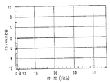
図1には、フィルタの振幅特性が示されている。このフィルタは100Hzあたりの領域で帯域阻止特性を有している。周波数は対数目盛りでプロットされており、阻止帯域はほぼ30Hzであることが見て取れる。このフィルタは、高周波側よりも低周波数の方向においてより緩やかな振幅降下を有している。減衰はほぼ20dBである。その他の部分では振幅曲線は平坦である。
【0024】
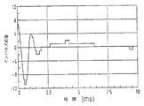
図1のこのフィルタに対して、計算によってインパルス応答を求めると、減衰部分に図2に示されるような時間的な曲線が得られる。インパルス応答のこの部分は、ほぼ40msの持続時間を有し、この場合ほぼ10個の振幅値零通過点を識別できる。時間が経過して行くにつれてインパルス応答の振幅は非常に小さくなるので、もはやオーディオ信号に著しい影響を及ぼさない。
【0025】
図1に振幅特性が示されているフィルタによるオーディオ信号のフィルタリングは、オーディオ信号をこのフィルタのインパルス応答に畳み込むことによって計算上行なわれる。この目的のために、標本化定理を考慮しつつ、このオーディオ信号をデジタル化する。すなわち、段階関数に変換する。同じ事は、インパルス応答によって行われ、このインパルス応答に対するサンプリング・レートがオーディオ信号のサンプリング・レートと等しいように選択される。
【0026】
デジタル化の結果、畳み込み積分は畳み込み和になる。この畳み込み和は、次式で表される。
【0027】
【数1】

ここで、
Ot=時点tにおけるフィルタの出力信号の振幅、
hi=インパルス応答のi番目のサンプル値、
st−i=時点t−iにおけるオーディオ信号のサンプル値、
N=インパルス応答のサンプル値の総数、
を意味する。
【0029】
この式から容易にわかるように、各時点tに対して、インパルス応答のサンプル値の総数に表されているインパルス応答の長さと同じ個数の積を連続して計算しなくてはならない。得られた積は次に加算されなければならない。この演算はリアルタイムで実施されなければならないので、計算時間を減らすためには非常に高性能なコンピュータが必要である。
【0030】
計算コストを減らすためにウィンドウ法を利用する場合、図2のインパルス応答は、図3に示されている、導出されたインパルス応答に変形される。実際のインパルス応答のうち全部で0.5msの長さの区間だけが残っているが、その他の部分はゼロになる。このことによって、なるほど非常に計算コストは低減されるが、図3のインパルス応答を有するフィルタの振幅特性は、図4から見て取れるように、所望のフィルタの振幅特性とはもはやどんな類似点も持っていない。この図4は図3のインパルス応答を有するフィルタの振幅特性を示している。100Hz付近の帯域阻止特性は完全に消滅し、そのかわりに1kHzより小さい実質的に全ての周波数に対して振幅のわずかな低下が発生している。
【0031】
これに対してインパルス応答が本発明の方法で導き出される場合、近似インパルス応答h´(t)が発生する。またこの近似インパルス応答のうちの減衰部分だけを図5に図示する。利用される方法に応じて、この近似インパルス応答は測定技術によって現れるか又は計算によってただ仮想的にのみ存在する。以下ではより理解を深めるために、この近似インパルス応答が存在するものと仮定して説明を進める。このインパルス応答h´(t)を作り出すために、サンプリング間隔のほぼ10倍の大きさの持続時間を有する量子化ステップが利用される。
【0032】
さらに簡略化するために、その他に図2のインパルス応答h(t)の所定の閾値より下の振幅値をゼロに設定する。完全な近似インパルス応答h´(t)を周波数領域へ変換することにより図6の振幅特性が得られる。非常に低い周波数における振幅曲線は、なるほどもはや図1の理想的な曲線の場合のように平坦ではなく、ほぼ50Hzにおいてわずかな隆起を示している。しかし、100Hz付近の帯域阻止作用はほとんど図1と同じくらいよく現れている。ほぼ110Hzより上の比較的高い周波数においては、わずかな振動を無視すれば、振幅曲線は比較的平坦である。この振動は非常にわずかなので、音の印象を実際に劣化させない。
【0033】
近似インパルス応答h´(t)をはるかに粗くパターン化すると、畳み込み和はきわめて簡略化される。この利点をよりよく理解するために、図7では、図5の近似インパルス応答h´(t)の一区間をフィルタリングされるオーディオ信号s(t)の一区間の上に重ねて図示した。
【0034】
この場合、振幅比は一定のスケールに従って表示されてはいない。
【0035】
近似インパルス応答h´(t)をステップ状に変形した結果、この選択された実施例では、この近似インパルス応答h´(t)の2つの移行部分の間の間隔内にオーディオ信号s(t)の10個のサンプル値が入っている。従って、例えばt=1とt=10との間の範囲のオーディオ信号s(t)の値をt=1〜10のh´(t)の値で畳み込み計算を行うためには、t=1とt=10との間の範囲内で個々のサンプル値stを加算し、次にこの加算をt=1とt=10との間のこの範囲のインパルス応答のサンプル値のうちの1つと乗算すれば十分である。引き続き加算される、全部で10個の個々の積の代わりに、本発明の解決方法においては10個の項を加算し、1回の乗算を行う。これは明らかな計算時間低減を意味する。
【0036】
不可避の計算コストをさらに低減することは、時点t=2に対して全部の和を新たに形成する必要がない、ということから得られる。前にt=1からt=10までの範囲に対して計算された結果からサンプル値st=−1を差し引き、その代わりにサンプル値st=−11を加算すれば十分である。この得られた結果を新たに近似インパルス応答h´(t)のt=1からt=10までの範囲のサンプル値のうちの1つで新たに乗算する。
【0037】
図7の一部分に図示された近似インパルス応答は、オーディオ信号と同じサンプリング・レートで生成されたインパルス応答として解釈することもできる。しかし、このインパルス応答においては、高いレートでサンプリングされたインパルス応答の真の曲線に依存せずに、複数の(ここに図示された例では10個の)サンプリング間隔にわたってサンプル値が一定に保持されている。もしくは、この近似インパルス応答は、そのサンプリング・レートが見たところ相応の値だけ遅いインパルス応答と解釈することができる。すなわち、このインパルス応答のサンプル値は、オーディオ信号のサンプリング間隔より大きい時間間隔を相互に有している。
【0038】
有利には、この近似インパルス応答のステップ形状への変形は、振幅特性及び場合によっては位相特性(この位相特性は、便宜上上記の図には別個に示されていない)も所望の経過に最適に適応するように選択される。
【0039】
さらに、インパルス応答を同じ長さで持続するステップで近似するのではなく、近似インパルス応答とオリジナルの又は理想のインパルス応答との間の誤差ができるだけ小さくなる方向で、ステップの持続時間をインパルス応答の経過の中で変化させることによって、最適化を達成することができる。このような実施例を例えば図8及び9に示した。図8には理論上の又は理想的なインパルス応答が示されている。この理論上の又は理想的なインパルス応答は、ほぼ2.5msで終わる、比較的高周波のヘッドに続いて、はるかに低い周波数を有する減衰部分を持つ。この場合有利には、ステップ状に変形されたインパルス応答の近似は、このインパルス応答の「テール」の部分のステップ幅が(隆起の部分は除いて)極端に拡大されてほぼ3msの長さであるのに対して、このインパルス応答のヘッドの領域、すなわち0msと2.5msとの間の範囲においては小さいステップ幅によって行われる。
【0040】
結局、図9から同様に見て取れるように、インパルス応答のヘッドの領域では、オーディオ信号のサンプリング間隔と一致するステップの持続時間で処理することができる。このことは、図9では、区間的には、0msとほぼ0.5msとの間の範囲、ならびにほぼ0.75msと1.0msとの間の範囲、そしてさらに1.3msと1.5msとの間の部分の(実質的にはステップがないという意味で)平滑な曲線経過に示されている。
【0041】
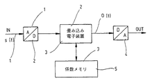
これまで詳細に記述してきたフィルタリングの方法は、図10に図示された回路によって実現される。この回路は、アナログ・デジタル変換器1を有する。このアナログ・デジタル変換器1にオーディオ信号s(t)がアナログ信号として供給される。この入力信号s(t)は、このアナログ・デジタル変換器1でデジタル化されたオーディオ信号に変換される。この際、標本化定理を満たすために、サンプリング周波数はオーディオ信号s(t)に含まれる最大周波数の少なくとも2倍の大きさである。このようにデジタル化されたオーディオ信号s(t)は、畳み込み電子装置2に供給される。この畳み込み電子装置2は実質的には計算ユニットであり、この計算ユニットにはメモリ3が接続されている。このメモリ3には、プログラムのほかに、所望のフィルタの本発明による近似インパルス応答h´(t)のサンプル値も格納されている。この計算ユニット2では、畳み込み積分の近似計算のための、これまで説明してきた和の形成及び乗算が実施される。こうして得られた信号は出力信号O(t)であり、しかもデジタル化された形式である。だれもこの出力信号をさらに処理する必要がない限りは、この出力信号は、後置接続されたデジタル・アナログ変換器4でフィルタ処理されたアナログオーディオ信号に逆変換される。
【0042】
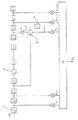
図11は、FIRフィルタと本発明の畳み込み計算を混合して利用しつつ処理する装置の構成を図示している。遅延素子5は所定のサンプリング周波数によるデジタル化に相応し、比較的短い持続時間のステップの場合には、各遅延素子5の後で、オーディオ信号s(t)の供給された値が、インパルス応答の相応のサンプル値hiで乗算される。比較的長い期間にわたって長く持続するステップによってインパルス応答が処理される領域では、信号は、相応の個数の遅延素子5にわたって他の処理なしに引き続きクロック制御される。そして、加算器6で新たに到着したサンプル値が加算され、他方でこの区間の最後のサンプル値が、段7において符号反転された後で、メモリ8に保持された元の合計値から差し引かれる。こうして得られた結果は、インパルス応答のサンプル値h´lで乗算される。ここで、h´lは、本発明により生成された値である。
【0043】
またこの場合、FIRフィルタの必要とするタップの数が非常に少ないという点で、著しい簡略化が達成される。
【0044】
デジタル化されたオーディオ信号においては、このデジタル化されたオーディオ信号を同様にデジタル化されたインパルス応答と畳み込み計算することによってフィルタリングが行われる。特別な手段をとらないならば、この畳み込みは、リアルタイムで実施しなくてはならない大量の計算処理回数を必要とする。
【0045】
この回数を低減するために、インパルス応答を近似する。この近似されたインパルス応答では、当該区間の範囲内の相互に隣接する間隔において、基礎となるインパルス応答の真の曲線とは関係なく、複数のサンプリング間隔にわたってサンプル値は一定に保持される。各区間内で一定に保持されるサンプル値の大きさは、当該区間内に現れる基礎となるインパルス応答の任意のサンプル値の大きさ、例えば当該区間内に現れるその都度最初の、オリジナルインパルス応答のサンプル値の大きさに相応する。
【図面の簡単な説明】
【図1】100Hzあたりの領域で減衰する帯域阻止フィルタの振幅特性を示す線図である。
【図2】図1のフィルタのインパルス応答の減衰部分を示す線図である。
【図3】図2のインパルス応答から導かれる、従来技術に従ってウィンドウ法によって修正されたインパルス応答を示す線図である。
【図4】図3のインパルス応答に所属する振幅特性を示す線図である。
【図5】図2のインパルス応答に近似された本発明のインパルス応答を示す線図である。
【図6】図5のインパルス応答に所属する振幅特性を示す線図である。
【図7】一定のスケールでではないが、大きく時間的に引き延ばした、図5のインパルス応答の一部分とデジタル化されたオーディオ信号の一部分とを一緒に示した線図である。
【図8】別のインパルス応答の線図である。
【図9】図8のインパルス応答から導かれる本発明のインパルス応答の線図である。
【図10】フィルタ処理されたオーディオ信号を生成するための回路装置のブロック図である。
【図11】インパルス応答を比較的長い時間区間によって近似した、畳み込み計算用プロセッサの構成の一部分を示すブロック図である。
【符号の説明】
1 アナログ・デジタル変換器
2 畳み込み電子装置
3 メモリ
4 デジタル・アナログ変換器
5 遅延素子
6 加算器
7 段
8 メモリ[0001]
BACKGROUND OF THE INVENTION
The present invention relates to a method for filtering an audio signal having a predetermined maximum frequency component and a period related thereto, and an apparatus for filtering a digitized audio signal having a predetermined maximum frequency component and period related thereto.
[0002]
[Prior art]
Audio signal filtering is often required. For example, a predetermined spatial characteristic should be conveyed during reproduction. When recording, recording is often done in the immediate vicinity of the sound source. This leaves no consideration of the spatial components during recording. Without subsequent processing of the signal thus recorded, the listener does not have the same sound impression as a person in the space where the original performance was performed.
[0003]
However, if the effect of space on the listening of the sound is known, for example by measurement, the recorded audio signal can be converted back into an acoustic original signal by later filtering.
[0004]
In this case, it is not important in principle whether the reproduction is performed by a loudspeaker or headphones.
[0005]
If binaural effects are taken into account when filtering, also avoid the well-known “Im-Kopf-Lokalisation” phenomenon when playing with headphones. be able to. This understands the filtering of the audio signal by the transfer function of the listener's individual outer ear.
[0006]
The more accurate the filter can be taken into account during playback, the more realistic the sound will be.
[0007]
However, acoustic filters can be used to obtain a predetermined timbre or to raise or lower individual frequency regions. A so-called duplexer that assigns audio signals to different loudspeakers in a box is also an audio filter.
[0008]
In the time domain, each filtering can be represented by a convolution with a corresponding impulse response. If the audio signal is in digital form, each convolution is a time consuming operation. This operation consists of a large number of multiplications and additions. Accordingly, there are many attempts to reduce the computational cost required for this convolution.
[0009]
The simplest solution is the so-called window method. In this case, instead of using the entire impulse response for convolution, only a part of the impulse response is used. As a result, important information can be lost.
[0010]
In practice, only the beginning part of the impulse response is considered and the end part is windowed so as to be truncated. This end part contains parts that are important for fine structure (eg reverberation) at low and intermediate frequencies. This applies for example to a minimum phase filter or an approximate minimum phase filter.
[0011]
German Patent No. 4328620 proposed an algorithm that limits the impulse response to an audibly important part. This is certainly not an exact solution to the problem. However, by utilizing some shielding effects, the listener may not be aware of the difference between the reproduced audio signal and the original audio signal. In this case, only the portion of the impulse response that exceeds a predetermined threshold is used. This can greatly reduce the calculation cost.
[0012]
As described in the above patent document, the exact calculation of convolution for a 2 second impulse response, a 50 kHz sampling rate, and a 20 kHz audio signal bandwidth requires 5 × 10 9 times per second. Addition and multiplication are required.
[0013]
Under such circumstances, it is natural to search for a method for reducing the calculation cost for convolution.
[0014]
Another known means for reducing computational costs in digital filtering is described in the paper “Aufwand bei digitalfiltern gesenkt” published in “Elektronik” Heft 15 1988, S.82 ff. In this method, the audio signal is additionally filtered to halve the bandwidth of the audio signal. The audio signal is then sampled at half the sampling frequency. As a result of this means, all the high frequency sound frequency components disappear. That is, the utilization signal obtained after convolution has a significantly smaller bandwidth than the original audio signal. In other words, the reduction in computational cost is accepted by compromising the acoustic pattern.
[0015]
[Problems to be solved by the invention]
Accordingly, an object of the present invention is to provide a method and apparatus that allows a substantial reduction in the number of computations without adversely affecting the high frequency signal components of the audio signal and impulse response. is there.
[0016]
[Means for Solving the Problems]
The problem with the above method is that the audio signal is digitized using a sampling interval that is less than or equal to half the period of the predetermined maximum frequency form of the audio signal, and the predetermined impulse response characteristic is achieved. Providing a digitized impulse response associated with said filter characteristic, defined by a corresponding plurality of impulse response samples, providing a sample value of an approximate impulse response having the same value for at least one time interval; Here, this same value is an arbitrary sample value of the digitized impulse response in the above time interval, and this time interval has a longer duration than the above sampling interval, and the above approximate impulse response A convolution sum is formed from the sample values of the audio signal and the sample values of the audio signal. Wherein, it is solved by a method of filtering the audio signal.
A further problem with the above apparatus is that it has a filter having a predetermined filter characteristic, and has a convolution unit and a storage device connected to the convolution unit. A digitized impulse response associated with is provided, wherein the digitized impulse response is defined by a plurality of impulse response samples corresponding to the predetermined impulse response characteristic and by the convolution unit, A sample value of the approximate impulse response having the same value is provided for at least one time interval, where the same value is any sample value of the digitized impulse response in the time interval, and further A sample of the above approximate impulse response by a convolution unit And a sample value of the audio signal, a convolution sum is formed, and the storage unit stores a sample value of the approximate impulse response related to the filter characteristic, and filters the audio signal Solved by the device.
[0017]
DETAILED DESCRIPTION OF THE INVENTION
In calculating the output signal of the filter, the calculation is performed with the actual or virtual impulse response. This actual or virtual impulse response is compared to a real or true impulse response and approximated by a quantization step having a larger temporal duration. Within each quantization step, the sample values of all impulse responses contained within the quantization step are kept constant without depending on the actual curve of the true impulse response. As a result, the calculation cost can be greatly reduced. This means the following for the calculation of the sample value of the output signal of the filter. That is, within the audio signal section covered by the impulse response quantization step determined as described above, only the sample values of the audio signal are added, and the sum thus formed is then quantized by the impulse response step. This means that it is sufficient to multiply by the sample value. Obviously, only one multiplication and one addition is sufficient for each quantization step of the approximated impulse response. In the prior art, for each corresponding temporal region of the impulse response, the same number of additions and multiplications as the number of sample values contained in this region must be performed.
[0018]
On the other hand, in this new method, the acoustically significant effects of the middle and low frequencies and / or the acoustically significant effects of the attenuation part of the impulse response of the filter selected each time are preserved.
[0019]
Another simplification comes from: That is, instead of forming a completely new sum for the next point in time of the output signal, this unnecessary sample value is subtracted from the sum of the previously obtained sample values of the audio signal, Instead of, the newly appearing sample value is added. In an advantageous embodiment of the invention, if the impulse response of the filter has a zero-pass point, the zero-pass point of the sample value of the impulse response used for the calculation of the convolution sum, and the zero-pass point of the impulse response of the filter Match.
[0020]
The quantization step of the impulse response (hereinafter referred to as the approximate impulse response) used in the calculation must be at least half as large as the period of the most considered frequency. Assuming that intermediate frequencies in the audible range must also be taken into account, for example, to avoid “sound concentration in the head locally” and other acoustic effects, is it greater than 1/3000 seconds? Alternatively, it is sufficient to use an approximate impulse response having a time length equal to 1/3000 seconds. On the other hand, the audio signal has a frequency range reaching 15 kHz. Therefore, the time interval of the approximate impulse response is 10 times longer than the time interval of the audio signal. Considering this relationship and the above explanation, the number of multiplications and additions required per second with respect to the prior art is reduced to 1/5.
[0021]
If the duration of the quantization step of the approximate impulse response can be selected even longer, it will be realized that the number of necessary multiplications and additions is significantly reduced. In another advantageous embodiment of the invention, the value of the adjacent impulse response sample is a function of the impulse response value of the predetermined impulse response characteristic within an interval corresponding to the adjacent impulse response sample. .
[0022]
【Example】
Embodiments of the present invention will be described with reference to the accompanying drawings.
[0023]
FIG. 1 shows the amplitude characteristics of the filter. This filter has a band rejection characteristic in a region around 100 Hz. It can be seen that the frequency is plotted on a logarithmic scale and the stopband is approximately 30 Hz. This filter has a more gradual amplitude drop in the low frequency direction than on the high frequency side. The attenuation is approximately 20 dB. In other parts, the amplitude curve is flat.
[0024]
When the impulse response is obtained by calculation for this filter of FIG. 1, a temporal curve as shown in FIG. 2 is obtained in the attenuation portion. This part of the impulse response has a duration of approximately 40 ms, in which case approximately 10 amplitude value zero-passing points can be identified. As time goes on, the amplitude of the impulse response becomes so small that it no longer has a significant effect on the audio signal.
[0025]
The filtering of the audio signal by the filter whose amplitude characteristic is shown in FIG. 1 is performed computationally by convolving the audio signal with the impulse response of this filter. For this purpose, the audio signal is digitized taking into account the sampling theorem. That is, it is converted into a step function. The same is done by the impulse response, and the sampling rate for this impulse response is selected to be equal to the sampling rate of the audio signal.
[0026]
As a result of digitization, the convolution integral becomes a convolution sum. This convolution sum is expressed by the following equation.
[0027]
[Expression 1]
here,
O t = the amplitude of the output signal of the filter at time t,
h i = i th sample value of the impulse response,
s t−i = sample value of the audio signal at the time point ti,
N = total number of sample values of the impulse response,
Means.
[0029]
As can be easily understood from this equation, for each time point t, a product having the same number as the length of the impulse response represented by the total number of sample values of the impulse response must be continuously calculated. The resulting products must then be added. Since this operation must be performed in real time, a very high performance computer is required to reduce the calculation time.
[0030]
If the window method is used to reduce the computational cost, the impulse response of FIG. 2 is transformed into the derived impulse response shown in FIG. In the actual impulse response, only a section having a length of 0.5 ms remains, but the remaining part becomes zero. This greatly reduces the computational cost, but the amplitude characteristic of the filter with the impulse response of FIG. 3 no longer has any similarity to the desired filter's amplitude characteristic, as can be seen from FIG. Absent. FIG. 4 shows the amplitude characteristics of the filter having the impulse response of FIG. The band rejection characteristics near 100 Hz are completely extinguished, and instead, a slight decrease in amplitude occurs for substantially all frequencies below 1 kHz.
[0031]
On the other hand, when an impulse response is derived by the method of the present invention, an approximate impulse response h ′ (t) is generated. Further, only the attenuation part of the approximate impulse response is shown in FIG. Depending on the method used, this approximate impulse response appears by the measurement technique or exists only virtually by calculation. In the following, for further understanding, the description will be made assuming that this approximate impulse response exists. In order to produce this impulse response h ′ (t), a quantization step having a duration approximately ten times the sampling interval is utilized.
[0032]
For further simplification, the amplitude value below a predetermined threshold value of the impulse response h (t) in FIG. 2 is set to zero. By converting the complete approximate impulse response h ′ (t) to the frequency domain, the amplitude characteristic of FIG. 6 is obtained. The amplitude curve at very low frequencies is no longer as flat as in the ideal curve of FIG. 1, but shows a slight bump at approximately 50 Hz. However, the band rejection near 100 Hz appears almost as well as in FIG. At relatively high frequencies above approximately 110 Hz, the amplitude curve is relatively flat, ignoring slight vibrations. This vibration is so slight that it does not actually degrade the sound impression.
[0033]
Patterning the approximate impulse response h ′ (t) much more coarsely greatly simplifies the convolution sum. In order to better understand this advantage, FIG. 7 shows a section of the approximate impulse response h ′ (t) of FIG. 5 overlaid on a section of the audio signal s (t) to be filtered.
[0034]
In this case, the amplitude ratio is not displayed according to a certain scale.
[0035]
As a result of stepping the approximate impulse response h ′ (t), in this selected embodiment, the audio signal s (t) is within the interval between the two transition portions of the approximate impulse response h ′ (t). 10 sample values are included. Therefore, for example, in order to perform the convolution calculation of the value of the audio signal s (t) in the range between t = 1 and t = 10 with the value of h ′ (t) from t = 1 to 10, t = 1 And the individual sample values s t in the range between t = 10 and then this addition is performed with one of the sample values of the impulse response in this range between t = 1 and t = 10. Multiplication is sufficient. Instead of a total of 10 individual products that are subsequently added, the solution of the present invention adds 10 terms and performs one multiplication. This means a clear calculation time reduction.
[0036]
Further reduction of the unavoidable calculation cost comes from the fact that it is not necessary to form a new sum for the time t = 2. It is sufficient to subtract the sample value s t = -1 from the results previously calculated for the range t = 1 to t = 10 and add the sample value s t = -11 instead. The obtained result is newly multiplied by one of the sample values ranging from t = 1 to t = 10 of the approximate impulse response h ′ (t).
[0037]
The approximate impulse response illustrated in part of FIG. 7 can also be interpreted as an impulse response generated at the same sampling rate as the audio signal. However, in this impulse response, the sample value is held constant over multiple sampling intervals (10 in the example shown here) without relying on the true curve of the impulse response sampled at a high rate. ing. Alternatively, this approximate impulse response can be interpreted as an impulse response whose sampling rate is slow by an appropriate value. That is, the sample values of the impulse response have a time interval larger than the sampling interval of the audio signal.
[0038]
Advantageously, the transformation of this approximate impulse response into a step shape is optimized so that the amplitude characteristic and possibly also the phase characteristic (this phase characteristic is not shown separately in the above figure for convenience) are also optimal for the desired course. Selected to adapt.
[0039]
In addition, instead of approximating the impulse response with a step that lasts the same length, the step duration is adjusted so that the error between the approximate impulse response and the original or ideal impulse response is as small as possible. Optimization can be achieved by changing in the course. Such an embodiment is shown, for example, in FIGS. FIG. 8 shows the theoretical or ideal impulse response. This theoretical or ideal impulse response has a relatively high frequency head that ends in approximately 2.5 ms, followed by an attenuation portion with a much lower frequency. In this case, advantageously, the approximation of the stepped impulse response is such that the step width of the “tail” part of this impulse response is extremely widened (except for the raised part) and is approximately 3 ms long. On the other hand, in the area of the head of this impulse response, that is, in the range between 0 ms and 2.5 ms, it is performed with a small step width.
[0040]
Eventually, as can be seen from FIG. 9, the impulse response head region can be processed with the duration of the step corresponding to the sampling interval of the audio signal. This is shown in FIG. 9 that, in the interval, a range between 0 ms and approximately 0.5 ms, and a range between approximately 0.75 ms and 1.0 ms, and further 1.3 ms and 1.5 ms. The smooth curve course (in the sense that there is virtually no step) of the part between is shown.
[0041]
The filtering method described so far in detail is realized by the circuit shown in FIG. This circuit has an analog-to-
[0042]
FIG. 11 illustrates the configuration of an apparatus that performs processing while using a mixture of the FIR filter and the convolution calculation of the present invention. The
[0043]
In this case, a significant simplification is achieved in that the number of taps required by the FIR filter is very small.
[0044]
In a digitized audio signal, filtering is performed by convolving the digitized audio signal with a similarly digitized impulse response. If no special measures are taken, this convolution requires a large number of computations that must be performed in real time.
[0045]
In order to reduce this number of times, the impulse response is approximated. In this approximated impulse response, the sample values are kept constant over a plurality of sampling intervals, regardless of the true curves of the underlying impulse response, in mutually adjacent intervals within the interval. The magnitude of the sample value that is held constant in each interval is the size of any sample value of the underlying impulse response that appears in that interval, for example, the first of the original impulse response each time it appears in that interval. Corresponds to the size of the sample value.
[Brief description of the drawings]
FIG. 1 is a diagram showing amplitude characteristics of a band rejection filter that attenuates in a region around 100 Hz.
FIG. 2 is a diagram showing an attenuation part of an impulse response of the filter of FIG. 1;
FIG. 3 is a diagram illustrating an impulse response derived from the impulse response of FIG. 2 and modified by the window method according to the prior art.
4 is a diagram showing amplitude characteristics belonging to the impulse response of FIG. 3; FIG.
FIG. 5 is a diagram showing the impulse response of the present invention approximated to the impulse response of FIG.
6 is a diagram showing amplitude characteristics belonging to the impulse response of FIG.
7 is a diagram showing together a portion of the impulse response of FIG. 5 and a portion of the digitized audio signal, which are not scaled but greatly extended in time.
FIG. 8 is a diagram of another impulse response.
FIG. 9 is a diagram of the impulse response of the present invention derived from the impulse response of FIG.
FIG. 10 is a block diagram of a circuit device for generating a filtered audio signal.
FIG. 11 is a block diagram showing a part of the configuration of a convolution calculation processor that approximates an impulse response by a relatively long time interval;
[Explanation of symbols]
1 Analog /
Claims (17)
該方法では、
前記のオーディオ信号の所定の最大周波数形分の周期の半分以下であるサンプリング間隔を使用してオーディオ信号をデジタル化された形式にし、
前記の所定のインパルス応答特性に相応する複数のインパルス応答サンプルによって定められる、前記のフィルタ特性に関連するデジタル化されたインパルス応答を提供し、
少なくとも1つ時間区間の間、同じ値を有する近似インパルス応答のサンプル値を供給し、ここで当該の同じ値は、前記の時間区間におけるデジタル化されたインパルス応答の任意のサンプル値であり、該時間区間は、前記のサンプリング間隔より長い持続時間を有しており、
前記の近似インパルス応答のサンプル値と、前記のオーディオ信号のサンプル値とから畳込み和を形成することを特徴とする、
オーディオ信号をフィルタリングする方法。 In a method of filtering an audio signal having a predetermined maximum frequency component and a period associated therewith using a filter corresponding to a desired filter characteristic and having a predetermined impulse response characteristic ,
In the method,
The audio signal is digitized using a sampling interval that is less than half of the period of the predetermined maximum frequency form of the audio signal;
Providing a digitized impulse response associated with the filter characteristic defined by a plurality of impulse response samples corresponding to the predetermined impulse response characteristic;
Providing a sample value of an approximate impulse response having the same value for at least one time interval, wherein the same value is an arbitrary sample value of the digitized impulse response in said time interval; The time interval has a longer duration than the sampling interval,
A convolution sum is formed from the sample value of the approximate impulse response and the sample value of the audio signal ,
A method of filtering audio signals.
請求項1に記載の方法。 The time interval has a length of at least three times the sampling interval;
The method of claim 1.
請求項1に記載の方法。 The time interval has a length of at least 10 times the sampling interval;
The method of claim 1.
請求項1に記載の方法。 The time interval has a length of at least 50 times the sampling interval;
The method of claim 1.
請求項1に記載の方法。When having an impulse response zero crossing point of the filter, and the zero passage point of the sample values of the impulse response to be used in the calculation of the convolution sum, a zero crossing point of the impulse response of the filter Match ,
The method of claim 1.
請求項1に記載の方法。The width of the time interval is constant over a portion of the length of the impulse response or over the entire impulse response,
The method of claim 1.
請求項1に記載の方法。 In providing an approximate impulse response of the amplitude of the impulse response of the filter is set to zero sample values smaller impulse response than a predetermined value,
The method of claim 1.
該装置は、所定のフィルタ特性を有し、また畳み込みユニット(2)と、当該の畳み込みユニット(2)に接続された記憶装置(3)とを有しており、
前記の畳み込みユニット(2)により、前記のフィルタ特性に関連するデジタル化されたインパルス応答が供給され、ここで当該のデジタル化されたインパルス応答は、前記の所定のインパルス応答特性に相応する複数のインパルス応答サンプルによって定められ、また前記の畳み込みユニット(2)により、少なくとも1つ時間区間の間、同じ値を有する近似インパルス応答のサンプル値が提供され、ここで当該の同じ値は、前記の時間区間におけるデジタル化されたインパルス応答の任意のサンプル値であり、さらに前記の畳み込みユニット(2)により、前記の近似インパルス応答のサンプル値と、オーディオ信号のサンプル値とから畳込み和が形成され、
前記の記憶ユニット(3)によって、前記のフィルタ特性に関連した近似インパルス応答のサンプル値が記憶されることを特徴とする、
オーディオ信号をフィルタリングする装置。In an apparatus for filtering a digitized audio signal sampled at a sampling interval having a predetermined maximum frequency component and a period associated therewith and having a duration less than half of the period of said predetermined maximum frequency component ,
The device has a predetermined filter characteristic, and has a convolution unit (2) and a storage device (3) connected to the convolution unit (2) ,
The convolution unit (2) provides a digitized impulse response associated with the filter characteristic, wherein the digitized impulse response is a plurality of impulse responses corresponding to the predetermined impulse response characteristic. An approximate impulse response sample value defined by the impulse response sample and having the same value for at least one time interval is provided by the convolution unit (2), wherein the same value is Any sample value of the digitized impulse response in the interval, and the convolution unit (2) forms a convolution sum from the sample value of the approximate impulse response and the sample value of the audio signal,
The storage unit (3) stores sample values of approximate impulse responses related to the filter characteristics ,
A device that filters audio signals.
請求項8に記載の装置。 The time interval has a length of at least three times the sampling interval;
The apparatus according to claim 8.
請求項8に記載の装置。 The time interval has a length of at least 10 times the sampling interval;
The apparatus according to claim 8.
請求項8に記載の装置。 The time interval has a length of at least 50 times the sampling interval;
The apparatus according to claim 8.
請求項8に記載の装置。When having an impulse response zero crossing point of the filter, and the zero passage point of the sample values of the impulse response to be used in the calculation of the convolution sum, and the zero passage point of the impulse response of the filters Match ,
The apparatus according to claim 8.
請求項8に記載の装置。The width of the time interval is constant over a portion of the length of the impulse response or over the entire impulse response,
The apparatus according to claim 8.
請求項8に記載の装置。 When supplying the approximate impulse response, a sample value of the impulse response in which the amplitude of the impulse response of the filter is smaller than a predetermined value is set to zero.
The apparatus according to claim 8.
請求項1に記載の方法。The value of the impulse response samples the adjacent, in a section corresponding to the impulse response samples neighboring the is a function of the impulse response values of a predetermined impulse response characteristic of said,
The method of claim 1.
前記のデジタル化されたオーディオ信号を前記のサンプリング間隔だけ遅延する複数の直列接続された遅延素子と、
当該の直列接続された遅延素子によって形成された、デジタル化されたオーディオ信号が加算されるように構成した加算器と、
当該の加算器によって形成された和と、前記の所定のインパルス応答値を有するインパルス応答のうちの1つとを乗算する乗算器とを有する、
請求項8に記載の装置。The convolution unit further includes
A plurality of serially connected delay elements for delaying the digitized audio signal by the sampling interval ;
An adder configured to add digitized audio signals formed by the delay elements connected in series ;
Has a corresponding adders Thus formed sum, a multiplier for multiplying one of the impulse responses with a predetermined impulse response values of said,
The apparatus according to claim 8.
前記の第1の遅延素子の入力側に第1の入力側が接続されている加算素子(6)と、
前記の最後の遅延素子の出力側と、前記の加算素子(6)の第2の入力側との間に接続されかつ前記の遅延素子(5)からの出力を反転する符号反転素子(7)と、
前記の加算素子(6)の出力側と、当該の加算素子の第3の入力側との間に接続されかつ1サンプリング間隔前の当該の加算素子(6)の値を記憶するメモリ(8)と、
前記の加算素子(6)によって形成された和と、前記の近似インパルス応答のサンプル値と乗算する乗算素子を有する、
請求項16に記載の装置。 A plurality of serially connected delay elements (5) for delaying the digitized audio signal by the sampling interval;
An adder element (6) having a first input side connected to an input side of the first delay element;
A sign inversion element (7) connected between the output side of the last delay element and the second input side of the addition element (6) and inverting the output from the delay element (5) When,
A memory (8) connected between the output side of the adder element (6) and the third input side of the adder element and storing the value of the adder element (6) before one sampling interval When,
A multiplying element for multiplying the sum formed by the adding element (6) by the sample value of the approximate impulse response;
The apparatus of claim 16.
Applications Claiming Priority (2)
| Application Number | Priority Date | Filing Date | Title |
|---|---|---|---|
| DE19545623A DE19545623C1 (en) | 1995-12-07 | 1995-12-07 | Method and device for filtering an audio signal |
| DE19545623.8 | 1995-12-07 |
Publications (2)
| Publication Number | Publication Date |
|---|---|
| JPH09205345A JPH09205345A (en) | 1997-08-05 |
| JP4070835B2 true JP4070835B2 (en) | 2008-04-02 |
Family
ID=7779417
Family Applications (1)
| Application Number | Title | Priority Date | Filing Date |
|---|---|---|---|
| JP32511096A Expired - Fee Related JP4070835B2 (en) | 1995-12-07 | 1996-12-05 | Method and apparatus for filtering audio signals |
Country Status (6)
| Country | Link |
|---|---|
| US (1) | US6519342B1 (en) |
| EP (1) | EP0777326B1 (en) |
| JP (1) | JP4070835B2 (en) |
| AT (1) | ATE270470T1 (en) |
| DE (2) | DE19545623C1 (en) |
| DK (1) | DK0777326T3 (en) |
Families Citing this family (11)
| Publication number | Priority date | Publication date | Assignee | Title |
|---|---|---|---|---|
| DE19820908A1 (en) * | 1998-05-09 | 1999-11-11 | Thomson Brandt Gmbh | Computing least mean square algorithm for adaptive filter |
| GB9824776D0 (en) * | 1998-11-11 | 1999-01-06 | Kemp Michael J | Audio dynamic control effects synthesiser |
| AUPQ941600A0 (en) * | 2000-08-14 | 2000-09-07 | Lake Technology Limited | Audio frequency response processing sytem |
| DE10130524C2 (en) * | 2001-06-25 | 2003-10-30 | Siemens Ag | Device for reproducing audio signals and method for changing filter data |
| EP1740016B1 (en) * | 2005-06-28 | 2010-02-24 | AKG Acoustics GmbH | Method for the simulation of a room impression and/or sound impression |
| US20070168063A1 (en) * | 2006-01-18 | 2007-07-19 | Gallien Robert A | Programmable tone control filters for electric guitar |
| KR100884312B1 (en) * | 2007-08-22 | 2009-02-18 | 광주과학기술원 | Sound field generator and method of generating the same |
| EP2028883A3 (en) * | 2007-08-22 | 2012-11-28 | Gwangju Institute of Science and Technology | Sound field generator and method of generating sound field using the same |
| JP4702392B2 (en) * | 2008-04-28 | 2011-06-15 | カシオ計算機株式会社 | Resonant sound generator and electronic musical instrument |
| TWI524785B (en) * | 2008-11-21 | 2016-03-01 | 曙光科技股份有限公司 | Method of simplifying a model of an acoustic environment, method and converter for converting a first audio stream into a second audio stream |
| US11705148B2 (en) * | 2021-06-11 | 2023-07-18 | Microsoft Technology Licensing, Llc | Adaptive coefficients and samples elimination for circular convolution |
Family Cites Families (9)
| Publication number | Priority date | Publication date | Assignee | Title |
|---|---|---|---|---|
| US3696235A (en) * | 1970-06-22 | 1972-10-03 | Sanders Associates Inc | Digital filter using weighting |
| NL178640C (en) * | 1976-07-12 | 1986-04-16 | Philips Nv | DIGITAL SIGNAL PROCESSING DEVICE. |
| JPH03127599A (en) * | 1989-10-12 | 1991-05-30 | Matsushita Electric Ind Co Ltd | Sound field variable device |
| JP2569872B2 (en) * | 1990-03-02 | 1997-01-08 | ヤマハ株式会社 | Sound field control device |
| US5168459A (en) * | 1991-01-03 | 1992-12-01 | Hewlett-Packard Company | Adaptive filter using continuous cross-correlation |
| KR940002436B1 (en) * | 1991-02-13 | 1994-03-24 | 삼성전자 주식회사 | Control apparatus and method of a digital tone |
| JPH05265477A (en) * | 1992-03-23 | 1993-10-15 | Pioneer Electron Corp | Sound field correcting device |
| DE4328620C1 (en) * | 1993-08-26 | 1995-01-19 | Akg Akustische Kino Geraete | Process for simulating a room and / or sound impression |
| JP4023842B2 (en) * | 1995-09-28 | 2007-12-19 | ソニー株式会社 | Digital filter and sound reproduction device |
-
1995
- 1995-12-07 DE DE19545623A patent/DE19545623C1/en not_active Expired - Lifetime
-
1996
- 1996-12-04 DE DE59611028T patent/DE59611028D1/en not_active Expired - Lifetime
- 1996-12-04 EP EP96890182A patent/EP0777326B1/en not_active Expired - Lifetime
- 1996-12-04 DK DK96890182T patent/DK0777326T3/en active
- 1996-12-04 AT AT96890182T patent/ATE270470T1/en active
- 1996-12-05 JP JP32511096A patent/JP4070835B2/en not_active Expired - Fee Related
- 1996-12-09 US US08/762,497 patent/US6519342B1/en not_active Expired - Lifetime
Also Published As
| Publication number | Publication date |
|---|---|
| US6519342B1 (en) | 2003-02-11 |
| DK0777326T3 (en) | 2004-09-06 |
| DE19545623C1 (en) | 1997-07-17 |
| EP0777326B1 (en) | 2004-06-30 |
| EP0777326A3 (en) | 1998-04-08 |
| EP0777326A2 (en) | 1997-06-04 |
| ATE270470T1 (en) | 2004-07-15 |
| DE59611028D1 (en) | 2004-08-05 |
| JPH09205345A (en) | 1997-08-05 |
Similar Documents
| Publication | Publication Date | Title |
|---|---|---|
| KR100312636B1 (en) | Compensation Filter | |
| US6760451B1 (en) | Compensating filters | |
| US4066842A (en) | Method and apparatus for cancelling room reverberation and noise pickup | |
| EP0556867B1 (en) | Digital equalizer apparatus enabling separate phase and amplitude characteristic modification | |
| KR101193763B1 (en) | Unnatural reverberation | |
| EP2209116A1 (en) | High range interpolation device and high range interpolation method | |
| KR100721069B1 (en) | Audio apparatus and computer-readable medium including its reproduction program | |
| JP4070835B2 (en) | Method and apparatus for filtering audio signals | |
| JP2730860B2 (en) | Method and apparatus for compensating linear distortion of acoustic signal | |
| JPH11503882A (en) | 3D virtual audio representation using a reduced complexity imaging filter | |
| JP3810257B2 (en) | Voice band extending apparatus and voice band extending method | |
| JPH05265477A (en) | Sound field correcting device | |
| JP4023842B2 (en) | Digital filter and sound reproduction device | |
| JP3979133B2 (en) | Sound field reproduction apparatus, program and recording medium | |
| US20080285768A1 (en) | Method and System for Modifying and Audio Signal, and Filter System for Modifying an Electrical Signal | |
| KR100684029B1 (en) | Method for generating harmonics using fourier transform and apparatus thereof, method for generating harmonics by down-sampling and apparatus thereof and method for enhancing sound and apparatus thereof | |
| JP3109389B2 (en) | Adaptive filter system | |
| JP2757740B2 (en) | Distortion circuit | |
| JPH06289897A (en) | Speech signal processor | |
| JPH0590899A (en) | Circuit device acting on frequency response of digital aural signal | |
| EP0288159B1 (en) | Digital equalizer apparatus enabling separate phase and amplitude characteristic modification | |
| JP3255348B2 (en) | Delay amount control device and sound image control device | |
| US20050259833A1 (en) | Frequency responses, apparatus and methods for the harmonic enhancement of audio signals | |
| JP2755081B2 (en) | Sound image localization control method | |
| JPH09247799A (en) | Stereoscopic acoustic processing unit using linear prediction coefficient |
Legal Events
| Date | Code | Title | Description |
|---|---|---|---|
| A131 | Notification of reasons for refusal |
Free format text: JAPANESE INTERMEDIATE CODE: A131 Effective date: 20061020 |
|
| A521 | Request for written amendment filed |
Free format text: JAPANESE INTERMEDIATE CODE: A523 Effective date: 20070117 |
|
| A131 | Notification of reasons for refusal |
Free format text: JAPANESE INTERMEDIATE CODE: A131 Effective date: 20070419 |
|
| A601 | Written request for extension of time |
Free format text: JAPANESE INTERMEDIATE CODE: A601 Effective date: 20070718 |
|
| A602 | Written permission of extension of time |
Free format text: JAPANESE INTERMEDIATE CODE: A602 Effective date: 20070723 |
|
| A601 | Written request for extension of time |
Free format text: JAPANESE INTERMEDIATE CODE: A601 Effective date: 20070820 |
|
| A602 | Written permission of extension of time |
Free format text: JAPANESE INTERMEDIATE CODE: A602 Effective date: 20070823 |
|
| A601 | Written request for extension of time |
Free format text: JAPANESE INTERMEDIATE CODE: A601 Effective date: 20070919 |
|
| A602 | Written permission of extension of time |
Free format text: JAPANESE INTERMEDIATE CODE: A602 Effective date: 20070925 |
|
| A521 | Request for written amendment filed |
Free format text: JAPANESE INTERMEDIATE CODE: A523 Effective date: 20071019 |
|
| TRDD | Decision of grant or rejection written | ||
| A01 | Written decision to grant a patent or to grant a registration (utility model) |
Free format text: JAPANESE INTERMEDIATE CODE: A01 Effective date: 20071227 |
|
| A61 | First payment of annual fees (during grant procedure) |
Free format text: JAPANESE INTERMEDIATE CODE: A61 Effective date: 20080116 |
|
| R150 | Certificate of patent or registration of utility model |
Free format text: JAPANESE INTERMEDIATE CODE: R150 |
|
| FPAY | Renewal fee payment (event date is renewal date of database) |
Free format text: PAYMENT UNTIL: 20110125 Year of fee payment: 3 |
|
| FPAY | Renewal fee payment (event date is renewal date of database) |
Free format text: PAYMENT UNTIL: 20110125 Year of fee payment: 3 |
|
| FPAY | Renewal fee payment (event date is renewal date of database) |
Free format text: PAYMENT UNTIL: 20120125 Year of fee payment: 4 |
|
| FPAY | Renewal fee payment (event date is renewal date of database) |
Free format text: PAYMENT UNTIL: 20130125 Year of fee payment: 5 |
|
| LAPS | Cancellation because of no payment of annual fees |