JP4070311B2 - Wireless communication system - Google Patents
Wireless communication system Download PDFInfo
- Publication number
- JP4070311B2 JP4070311B2 JP21049898A JP21049898A JP4070311B2 JP 4070311 B2 JP4070311 B2 JP 4070311B2 JP 21049898 A JP21049898 A JP 21049898A JP 21049898 A JP21049898 A JP 21049898A JP 4070311 B2 JP4070311 B2 JP 4070311B2
- Authority
- JP
- Japan
- Prior art keywords
- base station
- antenna
- communication system
- signal
- output
- Prior art date
- Legal status (The legal status is an assumption and is not a legal conclusion. Google has not performed a legal analysis and makes no representation as to the accuracy of the status listed.)
- Expired - Fee Related
Links
Images


Classifications
-
- Y02B60/50—
Description
【0001】
【発明の属する技術分野】
本発明は、移動局と地上局間で無線通信を行うための無線通信システムであって、複数の基地局と移動局を含む無線通信システムにおける無線ゾーン切換方式に関するものである。
【0002】
【従来の技術】
従来、この種の無線通信システムにおいては、移動局が複数の基地局ゾーンにまたがって通信を行う場合、各基地局から異なる基地局識別信号を送信し、移動局では受信した基地局識別信号を基地局指定信号として返送するといった一連のシーケンスを使用することによって、移動局と基地局の接続を行う方式が一般的であった。この方式によれば、次のゾーンが空いている場合は、接続の継続が可能で、また必要なその移動局の存在するゾーンのみを占有するため、通信効率が良い利点がある。
【0003】
図2に従来の無線通信システムの一例を示す。図2において、1,2は電波の輻射および受信を行う漏洩同軸ケーブル(以下LCXケーブル)で、それぞれのケーブル毎に異なる無線ゾーンを構成する。
3はLCX1に接続されるLCX1ゾーンの基地局Aであり、共用器5、受信機6、送信機10、基地局識別信号発生器11をもって無線基地局を構成する。同様に、4はLCX2に接続されるLCX2ゾーンの基地局Bであって、共用器5′、受信機6′、送信機10′、基地局識別信号発生器11′をもって無線基地局を構成する。
各基地局は、異なる基地局識別信号を送信し、移動局は受信した基地局識別信号を基地局指定信号として返送する。また、各基地局は、制御装置30にそれぞれ接続され、移動局から返送された基地局指定信号を制御装置30に供給する。
制御装置30は、基地局指定信号検出器7および7′で検出された基地局指定信号に基づいて、切替器8を切り替えて受信する基地局系統を選択し、同様にして切替器12で送信基地局系統を選択している。回線接続装置9は制御装置30と電話等の端末とに接続されている。
一方、13は移動局40に接続されるアンテナ13で、このアンテナ13で受信された電波は、共用器を経由して受信機14で復調され、回線接続装置19に供給される。また、受信機14からの出力のもう一方は、基地局識別信号検出器16に供給され、その結果が回線接続装置19に出力される。回線接続装置19からの送信出力は、基地局識別信号に応じて、基地局指定信号と合成して送信機20、共用器を経由してアンテナ13で送信される。
【0004】
次に、図2に示す従来例の動作について解説する。図中、基地局A3内の基地局識別信号発生器11から発生した信号は、送信機10から送信され、共用器5を経由して、常時LCX1から送信される。同様に、基地局B4内の基地局識別信号発生器11′から発生した信号は、送信機10′から送信され、共用器5′を経由して常時LCX2から送信される。ただし、この識別信号は、LCX1ゾーンとLCX2ゾーンでは異なるものである。
移動局40がLCX1ゾーンを通過しているとき、移動局40のアンテナ13でLCX1からの電波を受信し、共用器、受信機14を経由して基地局識別信号検出器16で基地局識別信号が検出される。このとき、移動局40が送信する場合は、基地局指定信号としてLCX1ゾーンを指定する信号を付加して送信することにより、LCX1ゾーンの基地局A3と通信回線を接続する。
移動局40がLCX1ゾーンをはずれて隣接するLCX2ゾーンに入った場合は、移動局40のアンテナ13でLCX2ゾーンからの電波を受信することになり、基地局識別信号検出器でLCX2ゾーンの基地局B4の識別信号を検出する。送信するときの基地局指定信号は、LCX2ゾーンを指定することにより、LCX2ゾーンの基地局B4と通信回線を接続する。
【0005】
一方、移動局40が異なるゾーンの中間にいる場合は、LCX1ゾーンからの電波とLCX2ゾーンからの電波が混在している期間、信号の受信ができず、接続断の状態になってしまう。また、次のLCX2ゾーン識別信号を検出するまでの期間も接続断の状態になってしまう。これは、LCXケーブルからはずれた位置にあっても、至近の距離であれば電波が届くという電波の性質のためで、複数のLCX間の距離が短ければこの混信の区間は長くなり、一方長ければ次のゾーンに入るまでの時間が長くなるため、混信の時間は少ないが、電波のきわめて弱い状態が長く続くことになり、結果的に十分に電波が受信できないことになる。
このように、従来の技術では、ゾーンの境目のような電波が混在しているような場所では、混信している時間と再検出に要する時間の瞬断が確実に起きる。この問題は、単に従来の空間ダイバシテイ技術を用いても、受信系の動作が単一なため、基本的なシーケンスは単一のアンテナで受信した場合と異ならない。
たとえば、左右にアンテナを配置した場合、電波の受信状態は単独アンテナの場合と全く同様で、電波の受信が困難な時間が生じるためやはり同様の瞬断が起きる。また、前後にアンテナを配置した場合は、それぞれのゾーンごとに受信する電波が異なるため、結果的に十分な電波の受信のできない状態が存在することになる。
【0006】
【発明が解決しようとする課題】
このように、従来技術によるゾーン切替方式では、前の基地局指定信号を受信してから次の基地局指定信号を受信するまでに、電波の混信による受信困難な区域を移動し終わって、さらに基地局指定信号を検出し終わるまでの時間を必要とする。このため、通話の途中であれば通話が一時聞こえなくなり、データ伝送の途中であればデータがとぎれることになる。
【0007】
【課題を解決するための手段】
本発明は、上記の問題を解決するため、移動局に、前方アンテナと、この前方アンテナから後方に所定の距離dを離して配置された後方アンテナと、前方アンテナで受信した信号を復調する第1の受信機と、後方アンテナで受信した信号を復調する第2の受信機と、第1の受信機の出力と第2の受信機の出力とを切り替え制御する切替制御部とを設けると共に、この切替制御部により、第1と第2の受信機で同一の基地局識別信号を受信したときはダイバーシティ受信を行うように制御し、第1の受信機で受信不能になったときは第2の受信機出力のみを選択制御し、第1と第2の受信機で異なる基地局識別信号を受信したときは第1の受信機出力のみを選択制御するようにしたものである。
【0008】
また、移動局の前方アンテナと後方アンテナ間の距離dを、当該無線通信システムにおける移動局の受信不能な区間長Lと、移動局で基地局識別信号を受信してから検出するための時間tを距離換算した距離xとを合わせた距離L+x以上に長く設定するようにしたものである。
【0009】
【発明の実施の形態】
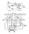
以下、本発明の一実施例を図1を参照して説明する。図1において、1はLCX1ゾーンを構成するLCX1、2はLCX2ゾーンを構成するLCX2、3はLCX1と接続されるLCX1ゾーンの基地局A、4はLCX2と接続されるLCX2ゾーンの基地局Bである。
図中、各ゾーンの基地局で受信された電波は、共用器5,5′を経由して受信機6,6′で復調される。また、各基地局から送信する場合は、基地局識別信号発生器11,11′からの基地局識別信号と送信信号とを合成して送信機10、10′で変調し、共用器5,5′を経由して各LCXケーブルより送信する。
【0010】
また、制御装置30には、各ゾーンの基地局で復調された信号が与えられ、基地局指定信号検出器7,7′で指定信号が検出される。この指定信号により指定された基地局側を切替器8で選択し、回線接続装置9に出力することにより通信回線を構成する。一方、回線接続装置9から出力された信号に基づき、切替器12にて識別信号で指定されている基地局側が選択され、指定された基地局の送信ラインへ接続される。
【0011】
一方、移動局50において、13は移動局前方に設置された前方アンテナで、13′は前方アンテナ13から後方に、少なくとも受信困難な区間長Lと、基地局識別信号を検出するための時間tを(例えば、移動局の最大速度または平均速度で)距離換算した距離xとを合わせた距離L+x以上に長い距離dを離して設置された後方アンテナである。アンテナ13,13′で受信された電波は、共用器を経由して受信機14,14′で復調される。この復調出力は、ダイバーシティ受信機15に入力され、何れか一方の受信状態が良い受信機出力(例えば、受信電界強度の強い方の出力)が選択される。このダイバーシティ選択を行った後に、一方の復調出力がダイバーシティ出力として切替器18に出力される。
また、受信機14,14′のもう一方の出力は二分され、その一方は切替器18に入力され、もう一方は基地局識別信号検出器16,16′に供給される。この検出器16,16′にて基地局識別信号が検出され、切替制御器17に入力される。切替制御器17は、図3に示すフローチャートに従って、切替器18,21を制御し、切り替えられた受信信号が回線接続装置19に入力される。
回線接続装置19は、基地局指定信号を合成した後に送信機20で変調され、切替器21を経由してアンテナ13若しくは13′に出力される。
各基地局内の基地局識別信号発生器11,11′から発生した識別信号は、送信機10,10′から送信され、共用器を経由して常時LCXケーブルから送信されている。ただし、この識別信号はLCX1ゾーンとLCX2ゾーンでは異なるものである。また、識別信号はアナログ信号であればトーン信号、ディジタル信号であれば固有のキーワードコード信号等とし、本来の送受信に大きく影響しない信号を使用する。
【0012】
本実施例では、図3に示す制御動作を行う切替制御器を用いて、ゾーン切替時において、瞬断を著しく低減した無線通信システムを実現することができる。次に、その動作について説明する。
移動局50がLCX1ゾーンを通過しているとき、移動局50の両方のアンテナ13,13′でLCX1からの基地局識別信号を受信し、検出結果が切替制御器17に与えられる。切替制御器17は、両方の受信手続きからLCX1ゾーンの識別信号を検出するので、切替器18に受信機のダイバーシティ結果を制御装置にわたすように制御する。また、送信アンテナを後方アンテナとし、基地局指定信号は後方アンテナで受信した基地局識別信号の基地局を選択する。
【0013】
次に、移動局50がLCX1ゾーンとLCX2ゾーンの境界に移動した場合、まず移動局の前方のアンテナ13は受信困難な状態になる。このとき、切替制御器17は前方アンテナ13による受信ができないため、後方アンテナ13′のみ有効となるように切替器18を制御する。また、送信アンテナは後方アンテナとし、基地局指定信号は後方アンテナで受信した基地局識別信号の基地局を選択する。
移動局50が進行するにつれて、前方アンテナ13がLCX2ゾーンに入り、LCX2ゾーンの基地局識別信号を受信する。また、このとき後方アンテナ13′は、前方アンテナ13と十分な距離lを持って設置されているため、まだLCX1ゾーンの基地局識別信号も受信している。
切替制御器17は、前方アンテナ13で受信した基地局識別信号と、後方アンテナ13′で受信した基地局識別信号が異なっているため、ゾーンの境目であることを認識し、前方アンテナ13の受信出力を制御装置へ渡すように制御する。さらに、送信アンテナも前方アンテナとなるようにし、基地局指定信号を前方アンテナで受信した基地局指定信号とする。この段階で、基地局はゾーンの切換を行うことになる。
【0014】
さらに、移動局が進行すると、後方アンテナ13′では受信困難な状態になるが、この場合は上の状態を維持し、前方アンテナ13のみで送受信する。
移動局50がゾーンの境目を完全に抜けてLCX2ゾーン内を移動していく段階では、前方アンテナと後方アンテナの両方で同じ基地局指定信号を受信するため、LCX1ゾーン内を移動していたときと同様に、ダイバーシティ受信、後方アンテナ送信となるように切り替え制御で制御する。
以上のように、前方のアンテナが受信できなくなっても後方のアンテナで受信可能であり、前方のアンテナが次のゾーンの電波を受信できるような状態になった段階で、前方アンテナのみの送受信に切り替え、次の基地局との送受信を確立してしまうことにより、瞬断時間を実質的に切替時間のみとすることができる。その後、後方アンテナからの受信が確立した段階で、ダイバーシティ受信にすることにより、通常モードに戻ることができる。
【0015】
【発明の効果】
本発明によれば、基地局ゾーンの境目でも、殆ど瞬断のない切り替えを行うことができ、通信不良の危険性を著しく低減した無線通信システムを実現することができる。
【図面の簡単な説明】
【図1】本発明の一実施例を示すブロック図。
【図2】従来の技術を示すブロック図。
【図3】本発明の無線ゾーン切替方式の一例を示すフローチャート。
【符号の説明】
1,2:LCXケーブル、 3:LCX1ゾーン基地局、
4:LCX2ゾーン基地局、 5,5′:共用器、
6,6′:基地局受信機、 7,7′:基地局指定信号検出器、
8:受信系統切替器、 9:回線接続装置、
10,10′:基地局送信機、 11,11′:基地局識別信号送信機、
13,13′:移動局アンテナ、 14,14′:移動局受信機、
15:ダイバーシティ受信機、 16,16′:基地局識別信号検出器、
17:切替制御器、 18:移動局受信系統切替器、
19:回線接続装置、 20:移動局送信機、
21:移動局送信系統切替器、 30:制御装置、
40,50:移動局。[0001]
BACKGROUND OF THE INVENTION
The present invention relates to a wireless communication system for performing wireless communication between a mobile station and a ground station, and relates to a wireless zone switching method in a wireless communication system including a plurality of base stations and mobile stations.
[0002]
[Prior art]
Conventionally, in this type of wireless communication system, when a mobile station communicates across a plurality of base station zones, a different base station identification signal is transmitted from each base station, and the received base station identification signal is transmitted from the mobile station. A method of connecting a mobile station and a base station by using a series of sequences such as returning as a base station designation signal has been common. According to this method, when the next zone is vacant, the connection can be continued, and only the zone in which the required mobile station exists is occupied.
[0003]
FIG. 2 shows an example of a conventional wireless communication system. In FIG. 2,
Each base station transmits a different base station identification signal, and the mobile station returns the received base station identification signal as a base station designation signal. Each base station is connected to the
Based on the base station designation signals detected by the base station
On the other hand, 13 is an
[0004]
Next, the operation of the conventional example shown in FIG. 2 will be described. In the figure, a signal generated from the base station identification signal generator 11 in the
When the
When the
[0005]
On the other hand, when the
As described above, in the conventional technique, in a place where radio waves are mixed, such as at the boundary of the zone, an instantaneous interruption between the time of interference and the time required for redetection occurs reliably. This problem is not different from the case where the basic sequence is received by a single antenna because the operation of the receiving system is single even if the conventional spatial diversity technique is used.
For example, when antennas are arranged on the left and right, the reception state of radio waves is exactly the same as in the case of a single antenna, and a similar momentary interruption occurs because a time during which reception of radio waves is difficult occurs. In addition, when antennas are arranged at the front and rear, the received radio waves are different for each zone, and as a result, there is a state where sufficient radio waves cannot be received.
[0006]
[Problems to be solved by the invention]
As described above, in the zone switching method according to the conventional technique, after the previous base station designation signal is received and the next base station designation signal is received, the zone has been moved in a difficult reception area due to radio wave interference. It takes time to detect the base station designation signal. For this reason, if the call is in progress, the call cannot be heard temporarily, and if the data is being transmitted, the data is interrupted.
[0007]
[Means for Solving the Problems]
In order to solve the above problem, the present invention demodulates a mobile station with a front antenna, a rear antenna disposed at a predetermined distance d behind the front antenna, and a signal received by the front antenna. 1 receiver, a second receiver that demodulates a signal received by the rear antenna, and a switching control unit that controls switching between the output of the first receiver and the output of the second receiver, By this switching control unit, when the same base station identification signal is received by the first and second receivers, control is performed so that diversity reception is performed, and when reception is disabled by the first receiver, the second is received. Only the first receiver output is selectively controlled when different base station identification signals are received by the first and second receivers.
[0008]
In addition, the distance d between the front antenna and the rear antenna of the mobile station is detected after the base station identification signal is received by the mobile station after the interval length L of the mobile station in the wireless communication system that cannot be received by the mobile station. Is set longer than the distance L + x, which is the sum of the distance converted distance x.
[0009]
DETAILED DESCRIPTION OF THE INVENTION
An embodiment of the present invention will be described below with reference to FIG. In FIG. 1, 1 is LCX1 constituting the LCX1 zone, 1 is LCX2 constituting the LCX2 zone, 3 is a base station A in the LCX1 zone connected to the LCX1, and 4 is a base station B in the LCX2 zone connected to the LCX2. is there.
In the figure, the radio waves received by the base stations in each zone are demodulated by
[0010]
The
[0011]
On the other hand, in the
Further, the other output of the receivers 14 and 14 'is divided into two, one of which is input to the
The
The identification signals generated from the base station identification signal generators 11 and 11 'in each base station are transmitted from the
[0012]
In the present embodiment, it is possible to realize a wireless communication system in which instantaneous interruption is significantly reduced at the time of zone switching by using the switching controller that performs the control operation shown in FIG. Next, the operation will be described.
When the mobile station 50 passes through the LCX1 zone, the base station identification signal from the LCX1 is received by both
[0013]
Next, when the mobile station 50 moves to the boundary between the LCX1 zone and the LCX2 zone, the
As the mobile station 50 travels, the
Since the base station identification signal received by the
[0014]
Further, when the mobile station advances, the rear antenna 13 'becomes difficult to receive. In this case, the upper state is maintained, and transmission / reception is performed only by the
At the stage where the mobile station 50 moves completely through the zone boundary and moves within the LCX2 zone, the same base station designation signal is received by both the front antenna and the rear antenna. In the same manner as above, control is performed by switching control so that diversity reception and rear antenna transmission are performed.
As described above, even if the front antenna can no longer be received, it can be received by the rear antenna, and when the front antenna is ready to receive radio waves in the next zone, only the front antenna can be transmitted and received. By switching and establishing transmission / reception with the next base station, the instantaneous interruption time can be made substantially only the switching time. After that, when reception from the rear antenna is established, it is possible to return to the normal mode by performing diversity reception.
[0015]
【The invention's effect】
According to the present invention, it is possible to perform switching with almost no interruption even at the boundary between base station zones, and it is possible to realize a wireless communication system in which the risk of communication failure is significantly reduced.
[Brief description of the drawings]
FIG. 1 is a block diagram showing an embodiment of the present invention.
FIG. 2 is a block diagram showing a conventional technique.
FIG. 3 is a flowchart showing an example of a wireless zone switching method according to the present invention.
[Explanation of symbols]
1, 2: LCX cable, 3: LCX1 zone base station,
4: LCX2 zone base station, 5, 5 ′: duplexer,
6, 6 ': Base station receiver, 7, 7': Base station designation signal detector,
8: Receiving system switching unit, 9: Line connection device,
10, 10 ': base station transmitter, 11, 11': base station identification signal transmitter,
13, 13 ': Mobile station antenna, 14, 14': Mobile station receiver,
15: Diversity receiver 16, 16 ': Base station identification signal detector,
17: Switching controller, 18: Mobile station reception system switching unit,
19: Line connection device, 20: Mobile station transmitter,
21: Mobile station transmission system switch, 30: Control device,
40, 50: Mobile station.
Claims (4)
該基地局に無線回線を介して接続される移動局とを含む無線通信システムにおいて、
上記移動局に、前方アンテナと、
該前方アンテナから後方に配置された後方アンテナと、
前方アンテナで受信した信号を復調する第1の受信機と、
後方アンテナで受信した信号を復調する第2の受信機と、
該第1の受信機の出力と第2の受信機の出力とを切り替え制御する切り替え制御部とを具備し、
該切替制御部は、第1と第2の受信機で同一の基地局識別信号を受信したときは選択ダイバーシティ受信を行うように制御し、
何れかの受信機が受信不能になった場合は、もう一方の受信機出力を選択し、
第1と第2の受信機で異なる基地局識別信号を受信した場合は、予め定めた一方の受信機出力を選択するように構成したことを特徴とする無線通信システム。A plurality of base stations each transmitting a different base station identification signal;
In a wireless communication system including a mobile station connected to the base station via a wireless line,
The mobile station has a front antenna,
A rear antenna disposed rearward from the front antenna;
A first receiver for demodulating a signal received by the front antenna;
A second receiver for demodulating the signal received by the rear antenna;
A switching control unit that controls switching between the output of the first receiver and the output of the second receiver;
The switching control unit controls to perform selective diversity reception when the same base station identification signal is received by the first and second receivers,
If one receiver fails to receive, select the other receiver output,
A radio communication system characterized in that when the first and second receivers receive different base station identification signals, one of the predetermined receiver outputs is selected.
上記移動局の前方アンテナと後方アンテナ間の距離を、
当該無線通信システムにおける移動局の受信不能な区間長と、
移動局で上記基地局識別信号を検出するための時間を距離換算した距離とを合わせた距離以上に長く設定したことを特徴とする無線通信システム。The wireless communication system according to claim 1, wherein
The distance between the front antenna and the rear antenna of the mobile station
Section length of the mobile station incapable of receiving in the wireless communication system,
A radio communication system, characterized in that a time for detecting the base station identification signal at a mobile station is set longer than a distance obtained by combining a distance converted to a distance.
上記複数の基地局は、それぞれ異なるLCXケーブルに接続され、
該LCXケーブルを介して上記移動局と通信を行うように構成したことを特徴とする無線通信システム。The wireless communication system according to claim 1, wherein
The plurality of base stations are connected to different LCX cables,
A wireless communication system configured to communicate with the mobile station via the LCX cable.
該基地局に無線回線を介して接続され、前方にある第1のアンテナと後方にある第2のアンテナの少なくとも2つのアンテナを有する移動局とを含む無線通信システムの出力選択する方法であって、
該出力選択方法は、上記前方アンテナで受信した信号を復調する第1の復調ステップと、
上記後方アンテナで受信した信号を復調する第2の復調ステップと、
該第1との第2の復調ステップによって復調された信号の基地局識別信号を検出する検出ステップと、
該検出ステップによって得られた結果、前記第1と第2のアンテナが受信した前記基地局識別信号が異なる場合には各アンテナの予め定められた一方の受信信号を出力し、前記第1と第2のアンテナが受信した前記基地局識別信号が同一の場合には選択ダイバーシティ出力に切り替える切替ステップからなることを特徴とした無線通信システムの出力選択方法。A plurality of base stations each transmitting a different base station identification signal;
A method of selecting an output of a radio communication system including a mobile station connected to the base station via a radio line and having at least two antennas, a first antenna at the front and a second antenna at the rear. ,
The output selection method includes a first demodulation step for demodulating a signal received by the front antenna;
A second demodulation step for demodulating a signal received by the rear antenna;
A detection step of detecting a base station identification signal of the signal demodulated by the first and second demodulation steps;
As a result of the detection step , when the base station identification signals received by the first and second antennas are different , one predetermined reception signal of each antenna is output , and the first and second antennas are output . An output selection method for a radio communication system, comprising a switching step of switching to a selection diversity output when the base station identification signals received by two antennas are the same .
Priority Applications (1)
| Application Number | Priority Date | Filing Date | Title |
|---|---|---|---|
| JP21049898A JP4070311B2 (en) | 1998-07-27 | 1998-07-27 | Wireless communication system |
Applications Claiming Priority (1)
| Application Number | Priority Date | Filing Date | Title |
|---|---|---|---|
| JP21049898A JP4070311B2 (en) | 1998-07-27 | 1998-07-27 | Wireless communication system |
Publications (3)
| Publication Number | Publication Date |
|---|---|
| JP2000049683A JP2000049683A (en) | 2000-02-18 |
| JP2000049683A5 JP2000049683A5 (en) | 2005-10-20 |
| JP4070311B2 true JP4070311B2 (en) | 2008-04-02 |
Family
ID=16590365
Family Applications (1)
| Application Number | Title | Priority Date | Filing Date |
|---|---|---|---|
| JP21049898A Expired - Fee Related JP4070311B2 (en) | 1998-07-27 | 1998-07-27 | Wireless communication system |
Country Status (1)
| Country | Link |
|---|---|
| JP (1) | JP4070311B2 (en) |
Families Citing this family (3)
| Publication number | Priority date | Publication date | Assignee | Title |
|---|---|---|---|---|
| JP2008011310A (en) * | 2006-06-30 | 2008-01-17 | Hitachi Kokusai Electric Inc | Radio communication system |
| JP5553365B2 (en) * | 2012-03-05 | 2014-07-16 | 日本信号株式会社 | Wireless train control system |
| WO2014192620A1 (en) * | 2013-05-27 | 2014-12-04 | 日本電気株式会社 | Radio base station apparatus, radio communication system, radio communication method, and program thereof |
-
1998
- 1998-07-27 JP JP21049898A patent/JP4070311B2/en not_active Expired - Fee Related
Also Published As
| Publication number | Publication date |
|---|---|
| JP2000049683A (en) | 2000-02-18 |
Similar Documents
| Publication | Publication Date | Title |
|---|---|---|
| US5960330A (en) | Diversity gain controlled cell-site transmission to prevent traffic signals from propagating beyond reachable extent of control signals | |
| CA1311802C (en) | Diversity antenna communication system | |
| EP0556010B1 (en) | Diversity reception arrangement | |
| EP0590776B1 (en) | Radio telephone system with power control and additional receivers | |
| WO1997033389A1 (en) | Media access protocol for packet access within a radio cell | |
| JPS60214641A (en) | Space diversity communication system | |
| JPH08506463A (en) | Cordless telephone system and range switching control method | |
| JPH07184251A (en) | Method and device for preventing hit of mobile radio terminal equipment | |
| EP0406905A2 (en) | Dual donor booster system | |
| JP3484670B2 (en) | Satellite communication system | |
| EP0886391B1 (en) | Wireless diversity device for high power transmission radio signal | |
| JP4070311B2 (en) | Wireless communication system | |
| US5701590A (en) | Radio communication system for performing multi-channel access | |
| JP3402426B2 (en) | Diversity transmitting apparatus and method | |
| JPH01256234A (en) | Base station selecting circuit | |
| JP3877930B2 (en) | Wireless communication system | |
| JP4067607B2 (en) | Diversity wireless communication device with monitoring function | |
| JPH05252100A (en) | Mobile body communication system | |
| JPH10135873A (en) | Transmission output control system | |
| JPH07245577A (en) | Diversity communication equipment | |
| JP2000049683A5 (en) | ||
| JPH07212816A (en) | Diversity communication equipment | |
| JP3397307B2 (en) | Data and voice shared wireless communication device | |
| JP3480911B2 (en) | Wireless systems | |
| KR100298345B1 (en) | System of selection diversity for ct-2 system |
Legal Events
| Date | Code | Title | Description |
|---|---|---|---|
| A521 | Written amendment |
Free format text: JAPANESE INTERMEDIATE CODE: A523 Effective date: 20050701 |
|
| A621 | Written request for application examination |
Free format text: JAPANESE INTERMEDIATE CODE: A621 Effective date: 20050701 |
|
| A977 | Report on retrieval |
Free format text: JAPANESE INTERMEDIATE CODE: A971007 Effective date: 20070604 |
|
| A131 | Notification of reasons for refusal |
Free format text: JAPANESE INTERMEDIATE CODE: A131 Effective date: 20070703 |
|
| A521 | Written amendment |
Free format text: JAPANESE INTERMEDIATE CODE: A523 Effective date: 20070828 |
|
| TRDD | Decision of grant or rejection written | ||
| A01 | Written decision to grant a patent or to grant a registration (utility model) |
Free format text: JAPANESE INTERMEDIATE CODE: A01 Effective date: 20080115 |
|
| A61 | First payment of annual fees (during grant procedure) |
Free format text: JAPANESE INTERMEDIATE CODE: A61 Effective date: 20080115 |
|
| R150 | Certificate of patent or registration of utility model |
Free format text: JAPANESE INTERMEDIATE CODE: R150 |
|
| FPAY | Renewal fee payment (event date is renewal date of database) |
Free format text: PAYMENT UNTIL: 20110125 Year of fee payment: 3 |
|
| FPAY | Renewal fee payment (event date is renewal date of database) |
Free format text: PAYMENT UNTIL: 20120125 Year of fee payment: 4 |
|
| FPAY | Renewal fee payment (event date is renewal date of database) |
Free format text: PAYMENT UNTIL: 20120125 Year of fee payment: 4 |
|
| FPAY | Renewal fee payment (event date is renewal date of database) |
Free format text: PAYMENT UNTIL: 20130125 Year of fee payment: 5 |
|
| FPAY | Renewal fee payment (event date is renewal date of database) |
Free format text: PAYMENT UNTIL: 20130125 Year of fee payment: 5 |
|
| FPAY | Renewal fee payment (event date is renewal date of database) |
Free format text: PAYMENT UNTIL: 20140125 Year of fee payment: 6 |
|
| LAPS | Cancellation because of no payment of annual fees |