JP4070104B2 - Video encoding / decoding method, video encoding device, and video decoding device - Google Patents
Video encoding / decoding method, video encoding device, and video decoding device Download PDFInfo
- Publication number
- JP4070104B2 JP4070104B2 JP2002302298A JP2002302298A JP4070104B2 JP 4070104 B2 JP4070104 B2 JP 4070104B2 JP 2002302298 A JP2002302298 A JP 2002302298A JP 2002302298 A JP2002302298 A JP 2002302298A JP 4070104 B2 JP4070104 B2 JP 4070104B2
- Authority
- JP
- Japan
- Prior art keywords
- frame
- key frame
- decoding
- image
- backward
- Prior art date
- Legal status (The legal status is an assumption and is not a legal conclusion. Google has not performed a legal analysis and makes no representation as to the accuracy of the status listed.)
- Expired - Lifetime
Links
Images


Classifications
-
- H—ELECTRICITY
- H04—ELECTRIC COMMUNICATION TECHNIQUE
- H04N—PICTORIAL COMMUNICATION, e.g. TELEVISION
- H04N19/00—Methods or arrangements for coding, decoding, compressing or decompressing digital video signals
- H04N19/50—Methods or arrangements for coding, decoding, compressing or decompressing digital video signals using predictive coding
- H04N19/503—Methods or arrangements for coding, decoding, compressing or decompressing digital video signals using predictive coding involving temporal prediction
- H04N19/51—Motion estimation or motion compensation
- H04N19/537—Motion estimation other than block-based
- H04N19/543—Motion estimation other than block-based using regions
-
- H—ELECTRICITY
- H04—ELECTRIC COMMUNICATION TECHNIQUE
- H04N—PICTORIAL COMMUNICATION, e.g. TELEVISION
- H04N19/00—Methods or arrangements for coding, decoding, compressing or decompressing digital video signals
- H04N19/50—Methods or arrangements for coding, decoding, compressing or decompressing digital video signals using predictive coding
- H04N19/503—Methods or arrangements for coding, decoding, compressing or decompressing digital video signals using predictive coding involving temporal prediction
- H04N19/51—Motion estimation or motion compensation
- H04N19/527—Global motion vector estimation
Description
【0001】
【発明の属する技術分野】
本発明は、動画像符号化復号方法及び動画像符号化装置並びに動画像復号装置に関する。
【0002】
【従来の技術】
この種の従来例としては、H.261、H.263、MPEG−1、MPEG−2、MPEG−4などが知られている。これらを含む従来の多くの動画像符号化手法では、キーフレームの符号化及び動きベクトル推定共に固定した位置・サイズのブロックを単位に行われる。MPEG−4においては、4つのベクトルの使用は認められているが、基本的にブロックを分割するのみである(例えば特許文献1参照)。
【0003】
【特許文献1】
特開2000−287212号公報(図1、段落0007〜0015)
【0004】
【発明が解決しようとする課題】
ブロックべースの符号化の場合、符号量が十分でない場合や動きベクトル推定に失敗した場合、ブロックの境目がはっきり見える、いわゆるブロック歪の問題が生じる。また、動きベクトル推定の精度自体についても問題がある。すなわち、常に一定のサイズのブロックを単位に動き推定が行われるため、ブロック中に複数の動きのオブジェクトが存在した場合などに、正しい動きベクトルが求まらないときや、支配的な動きベクトルは正しく推定されても、ブロック内の本来別の動きベクトルを持つオブジェクトの部分のテクスチャが、この支配的な動きベクトルに引きずられる形で動き補償に用いられるときに、ブロック歪を引き起こしてしまうこともある。
【0005】
本発明は上記従来例の問題点に鑑み、非ブロックべースの動き補償を行うことにより、動き補償の関係する範囲内ではブロック歪は発生しない動画像符号化復号方法及び動画像符号化装置並びに動画像復号装置を提供することを目的とする。
【0006】
【課題を解決するための手段】
本発明は上記目的を達成するために、テクスチャの特性によって分割されたパッチを基本に動き推定・動き補償を行うようにしたものである。本発明はまた、予測漏れになった領域については、2重像やフレームアウトに対処するために使用キーフレームを部分的に切り替えるような大域動き補償を併用するようにしたものである。
【0007】
すなわち本発明によれば、時間的に前後した前キーフレーム及び後キーフレームのほぼ中間のタイミングにおける中間フレームのテクスチャをその性質に応じて多数のパッチ状に領域分割し、
前記中間フレームの領域分割された各パッチ画像について前キーフレーム、後キーフレームを基にそれぞれ前方向、後方向の動きベクトルを推定し、
前記推定した前方向及び後方向の動きベクトルの信頼性を評価して、動画像を前記前キーフレーム及び後キーフレームと、中間フレームのパッチ画像と、前方向及び後方向の動きベクトルと、信頼性を符号化し、
前キーフレーム近傍のタイミングのフレームを、前記前キーフレームと前記中間フレームのパッチ画像の間に前記前方向の動きベクトルを内挿して動き補償して復号し、
前記後キーフレーム近傍のタイミングのフレームを、前記中間フレームのパッチ画像と前記後キーフレームの間に前記後方向の動きベクトルを内挿して動き補償して復号し、
前記前キーフレーム及び後キーフレームの中間のタイミングのフレームを、前記信頼性が高い方の動きベクトルを内挿して動き補償して復号する動画像符号化復号方法が提供される。
【0008】
また本発明によれば、時間的に前後した前キーフレーム及び後キーフレームのほぼ中間のタイミングにおける中間フレームのテクスチャをその性質に応じて多数のパッチ状に領域分割する手段と、
前記中間フレームの領域分割された各パッチ画像について前キーフレーム、後キーフレームを基にそれぞれ前方向、後方向の動きベクトルを推定する手段と、
前記推定した前方向及び後方向の動きベクトルの信頼性を評価する手段と、
動画像を前記前キーフレーム及び後キーフレームと、中間フレームのパッチ画像と、前方向及び後方向の動きベクトルと、信頼性を符号化して伝送する手段とを、
有する動画像符号化装置が提供される。
【0009】
【発明の実施の形態】
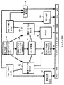
以下、図面を参照して本発明の実施の形態について説明する。図1は本発明に係る動画像符号化装置の一実施形態を示すブロック図、図2は本発明に係る動画像復号装置の一実施形態を示すブロック図である。
【0010】
図1に示す符号化装置(エンコード部)において、キーフレームは適当な従来法によるものとし、これらの時間的に前後するキ一フレームをそれぞれ前キーフレーム(Key Frame)F(t=Tf)、後キーフレーム(Key Frame)B(t=Tb)とし、これらのほぼ中間の時間(t=Tm)におけるフレームを中間フレーム(Frame)Mと呼ぶことにする。また、前キーフレームFを用いた予測を前方予測、後キーフレームBを用いた予測を後方予測、双方を用いた予測を双方向予測と呼ぶことにする。
【0011】
前キーフレームF、後キーフレームBはそれぞれ、符号化部1F、1Bにより従来の適当なコーディング法(例えばJPEG)により符号化し、圧縮データD1F、D1Bをビットストリーム(Bit Stream)化して伝送する。中間フレームMは自動セグメンテーション部2により、領域競合法で多数のパッチ状に領域分割される。この領域分割の結果(パッチ画像)Pは形状符号化部3により4-connected Freeman Chainで符号化される(データD2)。
【0012】
また、動きベクトル推定部4F、4Bにより、中間フレームMにおけるテクスチャ(輝度信号)の各パッチ領域について、それぞれ前後のキーフレームF、Bに対する動きベクトル推定(ハーフペル)を行う(データD3F、D3B)。ここでは、評価部5により、前方・後方のどちらの予測の信頼性(すなわち照合度)が高いかについても符号化する(データD4)。さらに、大域動き推定部6により、パッチ動き補償による予測漏れの対策として大域動き補償を行うために前キーフレームF・後キーフレームB間の大域動き推定を行う(データD5)。このエンコードにより、前後のキーフレームF、Bの間のフレームは、データD2、D3F、D3B、D4、D5に圧縮され、ビットストリーム化されて伝送される。
【0013】
図2に示す復号装置(デコード部)において、まず、前後のキーフレームF、Bは、それぞれデコード部11F、11Bにより従来手法でデコードされる。中間フレームMを含むキーフレームF、B間のフレームは、キーフレームのテクスチャと時間により内挿された動きベクトルによりパッチ動き補償される。パッチ動き補償は、
Tf<t<Tf+(Tb−Tf)/3
程度のタイミングのフレームについては、予測部12Fにより前方予測を行い、
Tf+(Tb−Tf)/3≦t<Tf+2*(Tb−Tf)
程度のタイミングのフレームについては、予測部12FBにより双方向予測を行い、
Tf+2*(Tb−Tf)≦t<Tb
程度のタイミングのフレームについて、予測部12Bにより後方予測を行う。なお、双方向予測については、信頼性の高い方のべクトルを採用する。
【0014】
パッチ動き補償による予測漏れについては、動き補償部(MC)13において大域動きベクトルの時間的内挿処理を行ったキーフレームを用いるが、前キーフレームF、後キーフレームBのどちらを使うかについては以下に従う。
・画像中央部/Tf<t≦Tm:後キーフレームB
・画像中央部/Tm<t<Tb:前キーフレームF
・画像縁端部/Tf<t≦Tm:前キーフレームF
・画像縁端部/Tm<t<Tb:後キーフレームB
理由については後記する。
【0015】
<各要素について>
・自動セグメンテーション部2(領域競合法によるセグメンテーション)
領域競合法[S. C. Zhu and A Yuille:" Region competition:unifying snakes, region growing,and Bayes/MDL for multiband image segmentation", IEEE Transactions on Pattern Analysis and Machine Intelligence, Vol、18, No.9(1996).]は、エネルギー汎関数最適化法の一種であり、隣接した複数の領域間でMDL規範が最小となる部分が成長し、その他の部分が縮小するようになっている。
【0016】
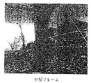
また、この際に領域境界に不自然な凹凸が発生しないように自動的に競合が調整される。この手法は領域成長・融合法と動的輪郭法の長所を兼ね備えたものである。ここでは輝度レベルを正規分布統計量として扱うグレースケールモデルを用いている。以下、本符号化手法における中間フレームを領域分割の実例を示しながら手順を説明する。ここで、図3以降に示す画像は一例として、前方に木があり、後方に家があるフラワーガーデンを示している。
【0017】
▲1▼例えば図3に示すような中間フレームの画像上に図4に示すようにl6×16の領域競合の種を敷きつめる。ここで、原典のような80画素の円形の種+背景でなく、このようにしたのは、高速の(繰り返し回数の少ない)分割を目指したからである。
▲2▼これを20回成長、競合させると図5のようになる。
▲3▼接触していて、かつ似ているテクスチャは同一領域であるとの仮定のもと、接触している2つの領域の平均と標準偏差の差の絶対値がそれぞれ、10,35未満の場合に融合する。図6は図5の396領域を252領域に減らしたものである。ここで、融合規準の評価を原典のエネルギー計算でなく、単純な統計量の比較で行ったのは主に計算量の理由である。
【0018】
・形状符号化部3(4-connected Freeman Chain)
上記のパッチ状に分割された領域を記述するにあたり、4-connected Freeman Chain Codingを用いた。4-connected Freeman Chain Codingの原理は非常に単純であり、領域境界上の一点から境界に沿って画素単位に移動するにあたり、上下左右どちらに移動するかについて、始点に戻ってくるまで符号化する。
【0019】
この方向については図7のように2ビットで表現できるので、この領域分割のパッチ画像についての必要な符号量は、
(領域数)*{始点(かつ終点)の座標の表現に必要なビット数} +(領域境界の総経路長)2
になる。ここで上記の結果を基に領域境界の総経路長を検討した結果、28850を得た。領域数を252、始点(かつ終点)の座標の表現に必要なビット数を18とすると、結果的には7.2kbyte程度である。
【0020】
・動き推定
ここで、図8、図9はそれぞれ、カメラ側が右側に移動した場合の前キーフレームF、後キーフレームBを示し、結果として前方の木が左側に移動した動画像である。前キーフレームFを図8、後キーフレームBを図9として、図3の中間フレームMを前方予測した結果を図10に示し、後方予測した結果を図11に示し、双方向予測した結果を図12に示す。これらを見ると、例えば、図10では図8において木の陰になった部分が再現されず、また図11では図9において木の陰になった部分が再現されていないのに対し、図12では良好な部分を選択的に用いているので、隠蔽部分の予測エラーが少ないことがわかる。ゆえにパッチ動き補償においては、t=Tf近傍では前方予測、t=Tm近傍では双方向予測、t=Tb近傍では後方予測を基本に動きベクトルを時間的に内挿して動き補償する。
【0021】
・大域動き補償
パッチ動き補償による予測漏れについて、大域動きベクトルの時間的内挿処理を行った前キーフレームF、後キーフレームBのテクスチャを下記(1)〜(4)のように用いると前述したが、(2)、(4)については(1)、(3)とt=Tmについて時間的に対称な現象になるので、ここでは(1)、(3)について説明する。
(1)画像中央部/Tf<t≦Tm:後キーフレームB
(2)画像中央部/Tm<t<Tb:前キーフレームF
(3)画像縁端部/Tf<t≦Tm:前キーフレームF
(4)画像縁端部/Tm<t<Tb:後キーフレームB
【0022】
Tf=0、Tm=14、Tb=29のとき、t=5におけるパッチ動き補償を行った結果を図13に示す。ここで、印のついた幹のダブったような部分はパッチ動き補償の予測エラーなので、以下の議論では除外して考える。予測漏れが発生するのは、主に、t=mでの予測において(この場合、図10)、前景物に隠蔽されたため、t=Tm近傍以外のタイミングでは(すなわち前景物が移動してしまうと)テクスチャが存在しない部分と、同じくt=Tmでの予測の時点でキーフレーム(t=Tf又はt=Tb;ここでは前者)において、前景物に隠蔽されたため動きベクトルに信頼性の望めない部分(この場合、具体的には図8で幹に隠蔽されている背景相当部分)である。図13では前者が幹の左側、後者が右側ということになる。
【0023】
これに対して、図14のように、前キーフレームFによる大域動き補償を行うと、概ねの背景について良好な結果を得るものの、印をつけた部分のようなダブリが生じてしまう。これは前キーフレームFのタイミング(t=Tf=0)とカレントフレームのタイミング(t=5)が比較的近いため、必然的に回避できない現象である。そこで、時間的に離れた後キーフレームB(t=Tb=29)を用いて大域動き補償を行った結果が図15である。大域動き補償としての品質はやや落ちるものの、ここではダブリが回避されている。ただし、時間差のため、大域的な動きとしては、後キーフレームB(t=Tb=29)は、カレントフレーム(t=5)よりかなり右に行ってしまっているため、画像左端の欠落を補填することはできない。そこで、目立つ画像中央部について後キーフレームBを使用し、縁端部の欠落を防ぐ目的で縁端部については前キーフレームFを使用した結果が図16である。現状では、予測誤差の処理を行っていないので、これが実質上のデコード結果になる。
【0024】
・実験結果
前の説明で一部結果も併記する形になったが、ここではt=Tf=0からt=Tb=29までの全体像を示すとともに、概略のビットレートを計算する。図17は復号結果の30フレームの全体像を示すとともに、パッチ動き補償の方向を示したものである。また、ビットレートについては、約1秒間に・JPEGで40kbyte弱相当のキーフレームが1枚・中間フレーム(t=Tm)については、パッチセグメンテーション情報が上記に示したように7.2kbyte程度、252領域の双方向のベクトルとそのどちらが信頼性が高いかの情報が大目に見積もって1kbyte以下・大域動きベクトル1本(上記と比べるとほぼ0)になり、総計は50kbyte/sec以下、すなわち400bps以下程度の符号量になると予測される。検討したフラワーガーデンの例では、CIF(352×288)、30fpsで400kbps以下の符号量になった。
【0025】
【発明の効果】
以上説明したように本発明によれば、テクスチャの特性によって分割されたパッチを基本に動き推定・動き補償を行い、予測漏れになった領域については、2重像やフレームアウトに対処するために使用キーフレームを部分的に切り替えるような大域動き補償を併用しているため、従来手法で見られたブロック歪を回避した高効率の符号化が可能になる。
【図面の簡単な説明】
【図1】本発明に係る動画像符号化装置の一実施形態を示すブロック図である。
【図2】本発明に係る動画像復号装置の一実施形態を示すブロック図である。
【図3】中間フレームを示す説明図である。
【図4】図3の中間フレームの領域競合の“種”を示す説明図である。
【図5】図4の20回の成長、競合後を示す説明図である。
【図6】図5の融合後を示す説明図である。
【図7】 4-connected Freeman Chain Codingを示す説明図である。
【図8】前キーフレームを示す説明図である。
【図9】後キーフレームを示す説明図である。
【図10】中間フレームの前方予測画像を示す説明図である。
【図11】中間フレームの後方予測画像を示す説明図である。
【図12】中聞フレームの双方向予測画像を示す説明図である。
【図13】パッチ動き補償のみの画像を示す説明図である。
【図14】前キーフレームによる大域動き補償画像を示す説明図である。
【図15】後キーフレームによる大域動き補償画像を示す説明図である。
【図16】本発明の復号画像を示す説明図である。
【図17】本発明の復号画像を示す説明図である。
【符号の説明】
1F、1B 符号化部
2 自動セグメンテーション部
3 形状符号化部
4F、4B 動きベクトル推定部
5 評価部
6 大域動き推定部
12F、12B、12FB 予測部
13 動き補償部[0001]
BACKGROUND OF THE INVENTION
The present invention relates to a video encoding / decoding method, a video encoding device, and a video decoding device.
[0002]
[Prior art]
As a conventional example of this type, H.P. 261, H.H. H.263, MPEG-1, MPEG-2, MPEG-4, and the like are known. In many conventional video encoding methods including these, both key frame encoding and motion vector estimation are performed in units of fixed position / size blocks. In MPEG-4, the use of four vectors is permitted, but basically only blocks are divided (see, for example, Patent Document 1).
[0003]
[Patent Document 1]
JP 2000-287212 A (FIG. 1, paragraphs 0007 to 0015)
[0004]
[Problems to be solved by the invention]
If the encoding of the block base over scan, if it fails or if the motion vector estimated code amount is not sufficient, the boundary of the blocks is clearly visible, so-called block distortion problems. There is also a problem with the accuracy of motion vector estimation itself. In other words, since motion estimation is always performed in units of a fixed size block, when there are multiple motion objects in the block, the correct motion vector cannot be obtained, or the dominant motion vector is Even if correctly estimated, the texture of the part of the object that originally has another motion vector in the block may cause block distortion when used for motion compensation in the form of being dragged by this dominant motion vector. is there.
[0005]
In view of the above problems of the prior art, by performing the motion compensation of the non-block base over scan, the moving picture coding decoding methods and moving image encoding apparatus block distortion does not occur within the relevant motion compensation An object of the present invention is to provide a moving picture decoding apparatus.
[0006]
[Means for Solving the Problems]
In order to achieve the above object, the present invention performs motion estimation / compensation based on patches divided according to texture characteristics. The present invention also uses global motion compensation that partially switches key frames to be used in order to deal with double images and frame-out in areas where predictions have been missed.
[0007]
That is, according to the present invention, the texture of the intermediate frame at almost the intermediate timing between the previous key frame and the subsequent key frame that are temporally changed is divided into a large number of patches according to the property,
Estimating the forward and backward motion vectors based on the previous key frame and the rear key frame for each patch image divided into regions of the intermediate frame,
The reliability of the estimated forward and backward motion vectors is evaluated, and the moving image is determined as the forward key frame and the backward key frame, the patch image of the intermediate frame, the forward and backward motion vectors, and the reliability. Encoding gender,
A frame at a timing near the previous key frame is decoded with motion compensation by interpolating the forward motion vector between the patch image of the previous key frame and the intermediate frame,
A frame at a timing near the rear key frame is decoded with motion compensation by interpolating the backward motion vector between the patch image of the intermediate frame and the rear key frame,
There is provided a moving picture coding / decoding method for decoding a frame having a timing intermediate between the preceding key frame and the following key frame by interpolating the motion vector having higher reliability and performing motion compensation.
[0008]
Further, according to the present invention, means for dividing the texture of the intermediate frame at a timing substantially in the middle of the previous key frame and the subsequent key frame, which are temporally changed, into a plurality of patches according to the nature thereof,
Means for estimating a forward motion vector and a backward motion vector based on a previous key frame and a rear key frame for each patch image divided into regions of the intermediate frame;
Means for evaluating the reliability of the estimated forward and backward motion vectors;
Means for transmitting a moving image by encoding the front key frame and the rear key frame, a patch image of an intermediate frame, motion vectors in the forward and backward directions, and reliability;
A moving image encoding apparatus is provided.
[0009]
DETAILED DESCRIPTION OF THE INVENTION
Embodiments of the present invention will be described below with reference to the drawings. FIG. 1 is a block diagram showing an embodiment of a moving picture encoding apparatus according to the present invention, and FIG. 2 is a block diagram showing an embodiment of a moving picture decoding apparatus according to the present invention.
[0010]
In the encoding device (encoding unit) shown in FIG. 1, key frames are assumed to be based on an appropriate conventional method, and these key frames that move back and forth in time are designated as previous key frames (Key Frame) F (t = Tf), The subsequent key frame (Key Frame) B (t = Tb) will be referred to as an intermediate frame (Frame) M. Also, the prediction using the front key frame F is referred to as forward prediction, the prediction using the subsequent key frame B is referred to as backward prediction, and the prediction using both is referred to as bidirectional prediction.
[0011]
The front key frame F and the rear key frame B are encoded by the
[0012]
Further, the motion
[0013]
In the decoding device (decoding unit) shown in FIG. 2, first, the preceding and following key frames F and B are decoded by the
Tf <t <Tf + (Tb−Tf) / 3
About the frame of about the timing, the prediction unit 12F performs forward prediction,
Tf + (Tb−Tf) / 3 ≦ t <Tf + 2 * (Tb−Tf)
About the frame of about the timing, bidirectional prediction is performed by the prediction unit 12FB,
Tf + 2 * (Tb−Tf) ≦ t <Tb
A backward prediction is performed by the prediction unit 12B for a frame at a certain timing. For bidirectional prediction, the more reliable vector is adopted.
[0014]
As for prediction omission due to patch motion compensation, a key frame that has been subjected to temporal interpolation of the global motion vector in the motion compensation unit (MC) 13 is used, but which of the previous key frame F and the subsequent key frame B is used. Follows.
Image center / Tf <t ≦ Tm: Rear key frame B
Image center / Tm <t <Tb: Previous key frame F
Image edge / Tf <t ≦ Tm: Previous key frame F
Image edge / Tm <t <Tb: rear key frame B
The reason will be described later.
[0015]
<About each element>
・ Automatic segmentation part 2 (segmentation by area competition method)
SC Zhu and A Yuille: “Region competition: unifying snakes, region growing, and Bayes / MDL for multiband image segmentation”, IEEE Transactions on Pattern Analysis and Machine Intelligence, Vol, 18, No. 9 (1996). ] Is a kind of energy functional optimization method, where a portion where the MDL criterion is minimized grows between a plurality of adjacent regions, and the other portions shrink.
[0016]
At this time, the competition is automatically adjusted so that unnatural unevenness does not occur in the region boundary. This method combines the advantages of the region growth / fusion method and the dynamic contour method. Here, a gray scale model is used in which the luminance level is treated as a normal distribution statistic. Hereinafter, the procedure will be described while showing an example of region division of the intermediate frame in the present encoding method. Here, as an example, the images shown in FIG. 3 and subsequent figures show a flower garden with a tree in the front and a house in the back.
[0017]
(1) For example, as shown in FIG. 4, seeds of 16 × 16 region competition are spread on the intermediate frame image as shown in FIG. Here, instead of the 80-pixel circular seed + background as in the original text, this was done because it aimed at high-speed (low repetition) division.
(2) When this is grown 20 times and competed, it becomes as shown in FIG.
(3) The absolute value of the difference between the average and standard deviation of the two areas in contact is less than 10, 35, assuming that the textures that are in contact and similar are in the same area. Merge in case. FIG. 6 is obtained by reducing the 396 area of FIG. 5 to the 252 area. Here, the reason why the fusion criterion was evaluated not by using the original energy calculation but by comparing simple statistics was mainly the reason for the calculation amount.
[0018]
・ Shape coding unit 3 (4-connected Freeman Chain)
4-connected Freeman Chain Coding was used to describe the area divided into patches. The principle of 4-connected Freeman Chain Coding is very simple. When moving from one point on the region boundary to the pixel unit along the boundary, it is encoded until it returns to the starting point as to whether it moves up, down, left, or right .
[0019]
Since this direction can be expressed by 2 bits as shown in FIG. 7, the necessary code amount for the patch image of this area division is
(Number of areas) * {Number of bits required to express the coordinates of the start point (and end point)} + (Total path length of the area boundary) 2
become. Here, 28850 was obtained as a result of examining the total path length of the region boundary based on the above result. Assuming that the number of regions is 252 and the number of bits necessary for expressing the coordinates of the start point (and end point) is 18, the result is about 7.2 kbytes.
[0020]
Motion Estimation Here, FIGS. 8 and 9 respectively show a front key frame F and a rear key frame B when the camera side is moved to the right side, and as a result, moving images in which the front tree has moved to the left side. FIG. 8 shows the front key frame F, FIG. 9 shows the rear key frame B, FIG. 10 shows the result of forward prediction of the intermediate frame M in FIG. 3, FIG. 11 shows the result of backward prediction, and FIG. As shown in FIG. From these, for example, in FIG. 10, the shaded part of the tree in FIG. 8 is not reproduced, and in FIG. 11, the shaded part of the tree in FIG. 9 is not reproduced, whereas FIG. Since the good part is selectively used, it can be seen that there are few prediction errors in the concealment part. Therefore, in patch motion compensation, motion compensation is performed by temporally interpolating motion vectors based on forward prediction near t = Tf, bi-directional prediction near t = Tm, and backward prediction near t = Tb.
[0021]
- the prediction leakage due global motion compensation patch motion compensation, using global motion keyframe before time of performing the temporal interpolation process of the vector F, the texture of the rear keyframe B as follows (1) to (4) As described above, (2) and (4) are temporally symmetric with respect to (1) and (3) and t = Tm, and therefore (1) and (3) will be described here.
(1) Image center / Tf <t ≦ Tm: Rear key frame B
(2) Image center / Tm <t <Tb: Previous key frame F
(3) Image edge / Tf <t ≦ Tm: Previous key frame F
(4) Image edge / Tm <t <Tb: Rear key frame B
[0022]
FIG. 13 shows the result of patch motion compensation at t = 5 when Tf = 0, Tm = 14, and Tb = 29. Here, the doubled portion of the marked trunk is a prediction error of patch motion compensation, so it will be excluded in the following discussion. The reason why the prediction omission occurs mainly in the prediction at t = m (in this case, FIG. 10), since it is concealed by the foreground object, the foreground object moves at a timing other than the vicinity of t = Tm. And) In the key frame (t = Tf or t = Tb; here the former) at the time of prediction at t = Tm, the motion vector cannot be trusted because it is hidden by the foreground object. This is a portion (in this case, specifically, a background equivalent portion hidden in the trunk in FIG. 8). In FIG. 13, the former is the left side of the trunk and the latter is the right side.
[0023]
On the other hand, as shown in FIG. 14, when the global motion compensation by the previous key frame F is performed, a good result is obtained for the general background, but a doubled portion such as a marked portion is generated. This is a phenomenon that cannot be avoided because the timing of the previous key frame F (t = Tf = 0) and the timing of the current frame (t = 5) are relatively close. Accordingly, FIG. 15 shows the result of performing the global motion compensation using the key frame B (t = Tb = 29) after being separated in time. Although the quality as global motion compensation is slightly reduced, double is avoided here. However, because of the time difference, as a global movement, the rear key frame B (t = Tb = 29) has been moved to the right of the current frame (t = 5), so that the missing left edge of the image is compensated. I can't do it. Therefore, FIG. 16 shows the result of using the rear key frame B for the conspicuous center of the image and using the front key frame F for the edge for the purpose of preventing the lack of the edge. At present, since no prediction error processing is performed, this is a practical decoding result.
[0024]
Experimental Results Although some results have been described in the previous description, here, an overall image from t = Tf = 0 to t = Tb = 29 is shown and an approximate bit rate is calculated. FIG. 17 shows an overall image of 30 frames as a decoding result, and also shows the direction of patch motion compensation. As for the bit rate, the key segment corresponding to a little less than 40 kbytes in JPEG is about 1 bit for the bit rate. For the intermediate frame (t = Tm), the patch segmentation information is about 7.2 kbytes as shown above , 252 The information about which region's bidirectional vector and which one is more reliable is roughly estimated to be 1 kbyte or less and one global motion vector (nearly 0 compared to the above), and the total is 50 kbyte / sec or less, ie 400 bps The code amount is predicted to be about the following. In the studied flower garden example, the code amount was 400 kbps or less at CIF (352 × 288), 30 fps.
[0025]
【The invention's effect】
As described above, according to the present invention, motion estimation / compensation is performed on the basis of patches divided according to texture characteristics, and in order to cope with double images and frame-out in areas where predictions have been missed. Since the global motion compensation that partially switches the used key frame is used together, it is possible to perform highly efficient encoding that avoids the block distortion found in the conventional method.
[Brief description of the drawings]
FIG. 1 is a block diagram showing an embodiment of a video encoding apparatus according to the present invention.
FIG. 2 is a block diagram showing an embodiment of a video decoding apparatus according to the present invention.
FIG. 3 is an explanatory diagram showing an intermediate frame.
4 is an explanatory diagram showing a “seed” of region conflict in the intermediate frame in FIG. 3; FIG.
FIG. 5 is an explanatory view showing 20 times of growth and competition after FIG. 4;
6 is an explanatory view showing a state after the fusion of FIG.
FIG. 7 is an explanatory diagram showing 4-connected Freeman Chain Coding.
FIG. 8 is an explanatory diagram showing a previous key frame.
FIG. 9 is an explanatory diagram showing a rear key frame.
FIG. 10 is an explanatory diagram illustrating a forward predicted image of an intermediate frame.
FIG. 11 is an explanatory diagram illustrating a backward predicted image of an intermediate frame.
FIG. 12 is an explanatory diagram showing a bidirectional prediction image of a middle frame.
FIG. 13 is an explanatory diagram showing an image with only patch motion compensation;
FIG. 14 is an explanatory diagram showing a global motion compensated image by a previous key frame.
FIG. 15 is an explanatory diagram showing a global motion compensated image by a rear key frame.
FIG. 16 is an explanatory diagram showing a decoded image of the present invention.
FIG. 17 is an explanatory diagram showing a decoded image of the present invention.
[Explanation of symbols]
1F,
Claims (4)
前記中間フレームの領域分割された各パッチ画像について前キーフレーム、後キーフレームを基にそれぞれ前方向、後方向の動きベクトルを推定し、
前記推定した前方向及び後方向の動きベクトルの信頼性を評価して、動画像を前記前キーフレーム及び後キーフレームと、中間フレームのパッチ画像と、前方向及び後方向の動きベクトルと、信頼性を符号化し、
前キーフレーム近傍のタイミングのフレームを、前記前キーフレームと前記中間フレームのパッチ画像の間に前記前方向の動きベクトルを内挿して動き補償して復号し、
前記後キーフレーム近傍のタイミングのフレームを、前記中間フレームのパッチ画像と前記後キーフレームの間に前記後方向の動きベクトルを内挿して動き補償して復号し、
前記前キーフレーム及び後キーフレームの中間のタイミングのフレームを、前記信頼性が高い方の動きベクトルを内挿して動き補償して復号する動画像符号化復号方法。The texture of the intermediate frame at almost the intermediate timing between the front key frame and the rear key frame that are temporally changed is divided into a large number of patches according to the property,
Estimating the forward and backward motion vectors based on the previous key frame and the rear key frame for each patch image divided into regions of the intermediate frame,
The reliability of the estimated forward and backward motion vectors is evaluated, and the moving image is determined as the forward key frame and the backward key frame, the patch image of the intermediate frame, the forward and backward motion vectors, and the reliability. Encoding gender,
A frame at a timing near the previous key frame is decoded with motion compensation by interpolating the forward motion vector between the patch image of the previous key frame and the intermediate frame,
A frame at a timing near the rear key frame is decoded with motion compensation by interpolating the backward motion vector between the patch image of the intermediate frame and the rear key frame,
A moving picture coding / decoding method for decoding a frame having a timing intermediate between the preceding key frame and the following key frame by interpolating the motion vector having the higher reliability and performing motion compensation.
前記大域動き推定結果によりパッチによる予測漏れが発生する場合、
前記中間フレーム以前のフレームの画像中央部を、前記後フレームのテクスチャを使用することにより復号し、
前記中間フレーム以前のフレームの画像縁端部を、前記前フレームのテクスチャを使用することにより復号し、
前記中間フレーム以降のフレームの画像中央部を、前記前フレームのテクスチャを使用することにより復号し、
前記中間フレーム以降のフレームの画像縁端部を、前記後フレームのテクスチャを使用することにより復号することを特徴とする請求項1に記載の動画像符号化復号方法。Further encoding a moving image by estimating global motion between the previous key frame and the subsequent key frame;
When a prediction failure due to a patch occurs due to the global motion estimation result,
Decoding the middle part of the image before the intermediate frame by using the texture of the subsequent frame;
Decoding the image edge of the frame before the intermediate frame by using the texture of the previous frame;
Decoding the middle part of the image after the intermediate frame by using the texture of the previous frame,
The moving image coding / decoding method according to claim 1, wherein an image edge portion of a frame after the intermediate frame is decoded by using a texture of the subsequent frame.
前記中間フレームの領域分割された各パッチ画像について前キーフレーム、後キーフレームを基にそれぞれ前方向、後方向の動きベクトルを推定する手段と、
前記推定した前方向及び後方向の動きベクトルの信頼性を評価する手段と、
動画像を前記前キーフレーム及び後キーフレームと、中間フレームのパッチ画像と、前方向及び後方向の動きベクトルと、信頼性を符号化して伝送する手段とを、
有する動画像符号化装置。Means for dividing the texture of the intermediate frame at approximately the intermediate timing between the preceding and following key frames temporally before and after in time into a number of patches according to the nature of the texture;
Means for estimating a forward motion vector and a backward motion vector based on a previous key frame and a rear key frame for each patch image divided into regions of the intermediate frame;
Means for evaluating the reliability of the estimated forward and backward motion vectors;
Means for transmitting a moving image by encoding the front key frame and the rear key frame, a patch image of an intermediate frame, motion vectors in the forward and backward directions, and reliability;
A moving image encoding apparatus having the same.
前キーフレーム近傍のタイミングのフレームを、前記前キーフレームと前記中間フレームのパッチ画像の間に前記前方向の動きベクトルを内挿して動き補償して復号する手段と、
後キーフレーム近傍のタイミングのフレームを、前記中間フレームのパッチ画像と前記後キーフレームの間に前記後方向の動きベクトルを内挿して動き補償して復号する手段と、
前記前キーフレーム及び後キーフレームの中間のタイミングのフレームを、前記信頼性が高い方の動きベクトルを内挿して動き補償して復号する手段とを、
有する動画像復号装置。A moving picture decoding apparatus for decoding moving picture data encoded by the moving picture encoding apparatus according to claim 3,
Means for interpolating the motion vector in the forward direction between the previous key frame and the patch image of the intermediate frame, and decoding the frame at the timing near the previous key frame with motion compensation;
Means for interpolating the motion vector in the backward direction between the patch image of the intermediate frame and the rear key frame, and decoding the frame at the timing near the rear key frame with motion compensation;
Means for interpolating the motion vector having the higher reliability and decoding the frame at a timing intermediate between the preceding key frame and the following key frame,
A moving image decoding apparatus.
Priority Applications (2)
| Application Number | Priority Date | Filing Date | Title |
|---|---|---|---|
| JP2002302298A JP4070104B2 (en) | 2002-10-16 | 2002-10-16 | Video encoding / decoding method, video encoding device, and video decoding device |
| US10/684,832 US7305033B2 (en) | 2002-10-16 | 2003-10-15 | Method of encoding and decoding motion picture, motion picture encoding device and motion picture decoding device |
Applications Claiming Priority (1)
| Application Number | Priority Date | Filing Date | Title |
|---|---|---|---|
| JP2002302298A JP4070104B2 (en) | 2002-10-16 | 2002-10-16 | Video encoding / decoding method, video encoding device, and video decoding device |
Publications (3)
| Publication Number | Publication Date |
|---|---|
| JP2004140533A JP2004140533A (en) | 2004-05-13 |
| JP2004140533A5 JP2004140533A5 (en) | 2005-07-14 |
| JP4070104B2 true JP4070104B2 (en) | 2008-04-02 |
Family
ID=32450418
Family Applications (1)
| Application Number | Title | Priority Date | Filing Date |
|---|---|---|---|
| JP2002302298A Expired - Lifetime JP4070104B2 (en) | 2002-10-16 | 2002-10-16 | Video encoding / decoding method, video encoding device, and video decoding device |
Country Status (2)
| Country | Link |
|---|---|
| US (1) | US7305033B2 (en) |
| JP (1) | JP4070104B2 (en) |
Families Citing this family (10)
| Publication number | Priority date | Publication date | Assignee | Title |
|---|---|---|---|---|
| GB0307307D0 (en) * | 2003-03-29 | 2003-05-07 | Atelier Vision Ltd | Image processing |
| WO2006122063A2 (en) * | 2005-05-09 | 2006-11-16 | Ultrachip Inc. | Turbo motion jpeg |
| US8165205B2 (en) * | 2005-09-16 | 2012-04-24 | Sony Corporation | Natural shaped regions for motion compensation |
| WO2007063465A2 (en) * | 2005-11-30 | 2007-06-07 | Nxp B.V. | Motion vector field correction |
| US8116576B2 (en) * | 2006-03-03 | 2012-02-14 | Panasonic Corporation | Image processing method and image processing device for reconstructing a high-resolution picture from a captured low-resolution picture |
| CN101755455A (en) * | 2007-07-30 | 2010-06-23 | 日本电气株式会社 | Connection terminal, distribution system, conversion method, and program |
| JP2010004142A (en) * | 2008-06-18 | 2010-01-07 | Hitachi Kokusai Electric Inc | Moving picture encoder, decoder, encoding method, and decoding method |
| KR101638211B1 (en) * | 2008-12-19 | 2016-07-20 | 톰슨 라이센싱 | Video coding based on global movement compensation |
| KR20100093703A (en) * | 2009-02-17 | 2010-08-26 | 한국전자통신연구원 | Distributed video coder and decoder and controlling method for the same |
| CN101990093A (en) * | 2009-08-06 | 2011-03-23 | 索尼株式会社 | Method and device for detecting replay section in video |
Family Cites Families (4)
| Publication number | Priority date | Publication date | Assignee | Title |
|---|---|---|---|---|
| US5991447A (en) * | 1997-03-07 | 1999-11-23 | General Instrument Corporation | Prediction and coding of bi-directionally predicted video object planes for interlaced digital video |
| US6252975B1 (en) * | 1998-12-17 | 2001-06-26 | Xerox Corporation | Method and system for real time feature based motion analysis for key frame selection from a video |
| JP2000287212A (en) | 1999-03-31 | 2000-10-13 | Victor Co Of Japan Ltd | Image encoder |
| KR20020047031A (en) | 1999-04-17 | 2002-06-21 | 펄센트 코포레이션 | Method and apparatus for efficient video processing |
-
2002
- 2002-10-16 JP JP2002302298A patent/JP4070104B2/en not_active Expired - Lifetime
-
2003
- 2003-10-15 US US10/684,832 patent/US7305033B2/en active Active
Also Published As
| Publication number | Publication date |
|---|---|
| JP2004140533A (en) | 2004-05-13 |
| US20040161038A1 (en) | 2004-08-19 |
| US7305033B2 (en) | 2007-12-04 |
Similar Documents
| Publication | Publication Date | Title |
|---|---|---|
| US6192079B1 (en) | Method and apparatus for increasing video frame rate | |
| Song et al. | Video super-resolution algorithm using bi-directional overlapped block motion compensation and on-the-fly dictionary training | |
| Chen et al. | Error concealment of lost motion vectors with overlapped motion compensation | |
| US6600786B1 (en) | Method and apparatus for efficient video processing | |
| KR100736041B1 (en) | Method and apparatus for concealing error of entire frame loss | |
| US8239766B2 (en) | Multimedia coding techniques for transitional effects | |
| US20080285651A1 (en) | Spatio-temporal boundary matching algorithm for temporal error concealment | |
| KR101377370B1 (en) | Preprocessor method and apparatus | |
| JP2009510939A (en) | Encoder-assisted frame rate up-conversion using various movement models | |
| JP4070104B2 (en) | Video encoding / decoding method, video encoding device, and video decoding device | |
| KR100621005B1 (en) | Image error concealment apparatus and method | |
| KR20060027779A (en) | Method and apparatus for encoding/decoding video signal using temporal and spatial correlations between macro blocks | |
| KR20090041562A (en) | Frame interpolating device and frame rate up-converting apparatus having the same | |
| JP2011142663A (en) | Method and apparatus for efficient video processing | |
| JP3405788B2 (en) | Video encoding device and video decoding device | |
| Chen et al. | Spatio-temporal boundary matching algorithm for temporal error concealment | |
| Jo et al. | Error concealment for MPEG-2 video decoders with enhanced coding mode estimation | |
| KR20200093212A (en) | Apparatus and method for bi-sequential video error concealment | |
| JPH07274175A (en) | Method and apparatus for coding moving picture of low transmission rate by dynamic movement evaluation | |
| CN106878753B (en) | 3D video residual coding mode selection method using texture smoothing information | |
| JP4239894B2 (en) | Image encoding apparatus and image decoding apparatus | |
| Tang et al. | Error concealment with error level tracking and backward frame update | |
| Yu et al. | Video error concealment via total variation regularized matrix completion | |
| Huang et al. | An edge-based temporal error concealment for MPEG-coded video | |
| CN101917628A (en) | Whole-frame error concealment method based on adaptive block sizes |
Legal Events
| Date | Code | Title | Description |
|---|---|---|---|
| A711 | Notification of change in applicant |
Free format text: JAPANESE INTERMEDIATE CODE: A712 Effective date: 20040513 |
|
| RD04 | Notification of resignation of power of attorney |
Free format text: JAPANESE INTERMEDIATE CODE: A7424 Effective date: 20040517 |
|
| RD01 | Notification of change of attorney |
Free format text: JAPANESE INTERMEDIATE CODE: A7426 Effective date: 20040930 |
|
| A521 | Request for written amendment filed |
Free format text: JAPANESE INTERMEDIATE CODE: A523 Effective date: 20041112 |
|
| A621 | Written request for application examination |
Free format text: JAPANESE INTERMEDIATE CODE: A621 Effective date: 20051014 |
|
| A521 | Request for written amendment filed |
Free format text: JAPANESE INTERMEDIATE CODE: A821 Effective date: 20051014 |
|
| A977 | Report on retrieval |
Free format text: JAPANESE INTERMEDIATE CODE: A971007 Effective date: 20071218 |
|
| TRDD | Decision of grant or rejection written | ||
| A01 | Written decision to grant a patent or to grant a registration (utility model) |
Free format text: JAPANESE INTERMEDIATE CODE: A01 Effective date: 20071225 |
|
| A61 | First payment of annual fees (during grant procedure) |
Free format text: JAPANESE INTERMEDIATE CODE: A61 Effective date: 20080110 |
|
| R150 | Certificate of patent or registration of utility model |
Free format text: JAPANESE INTERMEDIATE CODE: R150 Ref document number: 4070104 Country of ref document: JP Free format text: JAPANESE INTERMEDIATE CODE: R150 |
|
| FPAY | Renewal fee payment (event date is renewal date of database) |
Free format text: PAYMENT UNTIL: 20110125 Year of fee payment: 3 |
|
| FPAY | Renewal fee payment (event date is renewal date of database) |
Free format text: PAYMENT UNTIL: 20110125 Year of fee payment: 3 |
|
| FPAY | Renewal fee payment (event date is renewal date of database) |
Free format text: PAYMENT UNTIL: 20120125 Year of fee payment: 4 |
|
| R250 | Receipt of annual fees |
Free format text: JAPANESE INTERMEDIATE CODE: R250 |
|
| FPAY | Renewal fee payment (event date is renewal date of database) |
Free format text: PAYMENT UNTIL: 20120125 Year of fee payment: 4 |
|
| S111 | Request for change of ownership or part of ownership |
Free format text: JAPANESE INTERMEDIATE CODE: R313115 |
|
| R350 | Written notification of registration of transfer |
Free format text: JAPANESE INTERMEDIATE CODE: R350 |
|
| FPAY | Renewal fee payment (event date is renewal date of database) |
Free format text: PAYMENT UNTIL: 20130125 Year of fee payment: 5 |
|
| R250 | Receipt of annual fees |
Free format text: JAPANESE INTERMEDIATE CODE: R250 |
|
| FPAY | Renewal fee payment (event date is renewal date of database) |
Free format text: PAYMENT UNTIL: 20130125 Year of fee payment: 5 |
|
| R250 | Receipt of annual fees |
Free format text: JAPANESE INTERMEDIATE CODE: R250 |
|
| EXPY | Cancellation because of completion of term |