JP4069397B2 - Bathroom unit - Google Patents
Bathroom unit Download PDFInfo
- Publication number
- JP4069397B2 JP4069397B2 JP08410498A JP8410498A JP4069397B2 JP 4069397 B2 JP4069397 B2 JP 4069397B2 JP 08410498 A JP08410498 A JP 08410498A JP 8410498 A JP8410498 A JP 8410498A JP 4069397 B2 JP4069397 B2 JP 4069397B2
- Authority
- JP
- Japan
- Prior art keywords
- drainage
- bathtub
- drain
- waterproof pan
- groove
- Prior art date
- Legal status (The legal status is an assumption and is not a legal conclusion. Google has not performed a legal analysis and makes no representation as to the accuracy of the status listed.)
- Expired - Fee Related
Links
Images


Description
【0001】
【発明の属する技術分野】
本発明は、浴槽からの溢れ湯を効率良く排水できるようにした浴室ユニットに関する。
【0002】
【従来の技術】
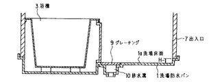
従来、浴室ユニットにおいては、図9に示すように、高齢者などが浴室ユニット内に出入りしやすいように、出入口7の段差Hを低くし、さらに、浴室ユニット内の洗場防水パン1から水が簡単に出入口7を乗り越えないように、洗場防水パン1の浴槽3側に溝蓋としてのグレーチング9を備えた排水溝10を凹設した構造のものが知られている(実開平4−130372号公報参照)。
【0003】
また、図10に示すように、浴槽3の上縁面3dに複数の排水孔3bを形成するとともに、浴槽3の側方の裏面3cとエプロン4とで囲まれる部分の底面2aに排水口6を設け、浴槽3の溢れ水を排水することにより出入口7の段差Hを少なくした構造の浴室ユニットも知られている(特開平9−13459号公報参照)。
【0004】
【発明が解決しようとする課題】
しかしながら、従来の技術で述べたもののうち、前者の図9に示した構造においては、排水溝10を覆うグレーチング9が必要であり、このグレーチング9が洗場床面1aに配置されることにより洗場床面1aのデザインが限定される、また、グレーチング9に髪の毛等が詰まると見栄えが悪く、また、清掃性も悪い。さらに、グレーチング9には人が乗ることもあるから、その重量に耐える強度が必要となって、コストアップになるとの課題がある。
【0005】
一方、後者の図10に示した浴室ユニットにおいては、上縁面3dに複数の排水孔3bを形成する特殊な浴槽が必要であり、また、複数の排水孔3bを有する上縁面3dは前者と同様に髪の毛等が詰まり易く、見栄えも悪く、清掃性も悪い。さらに、勢いよく入浴した場合に上縁面3dの排水孔3bで排水されず洗場床面1aにあふれるといった課題を有していたのである。
【0006】
本発明は、従来の技術が有するこのような課題に鑑みてなされたもので、出入口7の段差を低くして浴室への人の出入りを容易にするとともに、グレーチング9(図9参照)を不要として洗場の清掃が容易で、浴槽3からの溢れ湯が効率良く排水でき、さらには、洗場床面1aのデザインの多様化に対応でき、通常使用時の見栄えが良い、また、空間の有効利用が可能な浴室ユニットを安価に提供することを目的とする。
【0007】
【課題を解決するための手段】
上記目的を達成するために、請求項1記載の発明は、図1に示すように、洗場防水パン1と、該洗場防水パン1の洗場床面1aよりも高さが低くなっている底面2aに浴槽3が載置された浴槽防水パン2とを有する浴室ユニットにおいて、洗場防水パン1側の浴槽3側面に設けたエプロン4と、該エプロン4の下部と洗場床面1aとの間に形成され、洗場床面1aの湯水を排水するための排水隙間5と、該排水隙間5よりも浴槽3寄りの上記洗場防水パン1と浴槽防水パン2との間に配置され、浴槽防水パン2の上記底面2aよりも溝底面14aの高さが低く形成された排水溝部14と、該排水溝部14の溝底面14a側に形成された排水口15と、上記排水溝部14上に配置され、浴槽3に面した立上がり壁部11dの上部が浴槽防水パン2の上記底面2aよりも高く、かつ、下部が上記底面2aより低くなっている止水板11とを具備し、図2に示すように、上記止水板11Bは、上記排水溝部14に嵌め込まれた断面形状が略コ字型の部分と、上記コ字型の下部に形成された底面部11aに設けられた排水用孔13を有し、上記排水用孔13には、上記排水溝部14の排水口15に挿入された排水管12が接続されていることを特徴とする。
【0008】
請求項1記載の発明によれば、入浴時に浴槽3から洗場床面1aに溢れた湯水が、浴槽防水パン2側に流れ、エプロン4の下部と洗場床面1aとの排水隙間5を通り浴槽防水パン2側の排水溝部14に流れ込む。このとき、浴槽3からの溢れ湯に勢いがあっても、エプロン4の下部と洗場床面1aとの排水隙間5で効率良く飲み込まれ、さらに、止水板11に妨げられて浴槽防水パン2までは流れ込まず、排水口15から排水される。
【0009】
請求項2に記載の発明は、請求項1に記載の浴室ユニットにおいて、図1に示すように、洗場床面1aの排水勾配θをエプロン4側に向かってエプロン4と略直交する方向に設けたことを特徴とする。
【0010】
請求項2に記載の発明によれば、洗場床面1aのエプロン4側に向かった排水勾配により直接排水隙間5に流れ、洗場床面1aの排水が速やかに行なわれる。
【0011】
請求項3に記載の発明は、請求項1または請求項2に記載の浴室ユニットにおいて、図5に示すように、浴槽防水パン2の底面2aから、排水溝部14を囲む提部8を突設したことを特徴とする。
【0012】
請求項3に記載の発明によれば、提部8によって、排水溝部14の容量が大きくなる。
【0013】
請求項4に記載の発明は、請求項1、請求項2または請求項3に記載の浴室ユニットにおいて、図3に示すように、止水板11Cに、排水隙間5Cに位置して複数の排水孔11fを有する排水部11bを設けたことを特徴とする。
【0014】
請求項4に記載の発明によれば、止水板11Cに排水隙間5Cに位置する排水部11bを設けているため、石鹸等の小物が排水溝部14に流れ込むことがない。また、排水部11bは、入浴者が体重をかけることがないため、洗場床面1aに設ける従来のグレーチング9(図9参照)ほど強度が必要でなく、浴室ユニットを、軽量、清掃性良好、さらには、安価な構造に形成できる。
【0015】
請求項5に記載の発明は、請求項1、請求項2、請求項3または請求項4に記載の浴室ユニットにおいて、図1に示すように、止水板11の浴槽3に面した立上がり壁部11dの高さが、排水隙間5の上縁よりも高くなっていることを特徴とする。
【0016】
請求項5に記載の発明によれば、洗場床面1aからの排水水流の勢いが強い場合でも、浴槽防水パン2に排水が漏れ出すことがない。
【0018】
請求項6に記載の発明によれば、洗場床面1aからの溢れ湯は、排水隙間5を通って止水板11Bの断面形状コ字型の部分に流れ込み、直接排水溝部14の排水口15に排水される。そのため、浴槽防水パン2は清潔な状態が保たれる。また、コの字型の止水板11Bを取り外せば排水溝部14の清掃が容易に行なえる。
【0019】
【発明の実施の形態】
以下、本発明に係わる一実施形態を、図1〜図8を参照して説明する。
【0020】
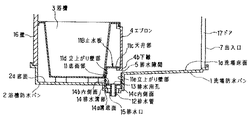
図1は、本発明の一実施の形態による浴室ユニットの断面図を示す。図1に示すように、この浴室ユニットは、洗場防水パン1および浴槽防水パン2を有し、各防水パン1、2の外周縁には壁16及びドア17が立設して形成される。また、浴槽防水パン2の底面2aは、洗場床面1aより高さが低くしてあり、上記底面2aに浴槽3の脚3e、3eを接するようにして浴槽3が設置され、浴槽側面3aの洗場防水パン1側に着脱自在のエプロン4を設け、該エプロン4の下部とエプロン4直下の洗場床面1aとの間には排水隙間5を設けてある。この排水隙間5よりも浴槽3寄りの上記洗場防水パン1と浴槽防水パン2との間、すなわち、エプロン4の裏面4aと浴槽3の側方の裏面3cとで囲まれる部分に、浴槽防水パン2の底面2aよりさらに高さの低い排水溝部14を設けてある。
【0021】
上記洗場床面1aの排水勾配θは、エプロン4側に向かってエプロン4と略直交する方向に設けて、洗場床面1aの溢れ湯の流れが直接排水隙間5に向かうようになっている。
【0022】
上記排水溝部14の溝底面14aは排水勾配が付けられ、その最下部に排水口15が設けられていて、排水溝部14に流れた浴槽3からの溢れ湯は、排水口15に向かい、外部へ排水される。
【0023】
また、上記排水溝部14には止水板11が配置されている。この止水板11は、排水溝部14の内側面14bの浴槽3側に沿って、溝底面14aから排水隙間5の上縁よりも高い位置まで立ち上げた立上がり壁部11dと、その上部に連なる天井部11cとで形成され、エプロン4または浴槽3の側方の裏面3cに着脱自在に取付けられる。この実施の形態では、上記天井部11cの縁は、エプロン4の下縁4bに引っ掛けて取り付けられている。このように止水板11が取り付けられることにより、浴槽3側の上記立上がり壁部11dの上部は、浴槽防水パン2の底面2aよりも高く、下部は、浴槽防水パン2の底面2aよりも低くなっていることになる。
【0024】
上記洗場防水パン1、排水溝部14および浴槽防水パン2は、一体に成形されたものでも、各々個別に成形されたものを合わせ面で接合されたものでもよい。
【0025】
浴槽3からの溢れ湯等は、洗場防水パン1で受けられ、その排水勾配によって直接排水隙間5に流れて吸い込まれ、排水溝部14に集まり、さらに、排水口15から速やかに排水される。排水溝部14に勢いよく湯水が流れ込んでも、止水板11によって妨げられ、湯水が浴槽防水パン2に入り込むことはない。
【0026】
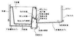
図2は、本発明の他の実施の形態による浴室ユニットの断面図を示す。図2の実施の形態では、止水板11Bとその配水管12以外は、図1の実施の形態と同様であるので、共通部分については、同一の符号を付して、その説明を省略する。
【0027】
図2に示した止水板11Bは、底面部11aと排水溝部14の両内側面14b、14cに沿わせた立上がり壁部11d、11eとで断面形状略コ字型(以下、コ字型とう)の部分を形成し、さらに、浴槽3側の立上がり壁部11dの上部から天井部11cを形成してある。洗場側の立上がり壁部11eは、洗場床面1aの延長線以下までの立上がりとしてある。止水板11Bのコ字型部分は、排水溝部14の内側に入る大きさとし、コ字型の部分の底面部11aに設けた排水用孔13に排水管12を接続してある。上記排水管12は排水溝部14の溝底面14aの排水口15に直接挿入されている。なお、上記止水板11Bは排水溝部14に着脱自在である。
【0028】
図2の止水板11Bを用いると、そのコ字型の部分に排水が入るから、排水溝部14に排水が多量に流れ込まず、排水溝部14が清潔に保たれる。
【0029】
図3は、本発明のさらに他の実施の形態による浴室ユニットの断面図を示す。図3の実施の形態では、止水板11C、エプロン4C以外は、図1に示す実施の形態と同様であるので、共通部分に付いては、同一の符号を付して、その説明を省略する。
【0030】
図3の実施の形態においては、エプロン4Cの高さを図1のエプロン4の高さよりもやや短くして、排水隙間5Cを大きくしてある。そして、この排水隙間5Cの略全幅を止水板11Cの天井部11cから下方へ延設した排水部11bで覆うようにしてある。排水部11bには複数の排水孔11fが設けられ、洗場からの湯水は、この排水孔11fを通して排水溝部14側へ排水される。
【0031】
上記止水板11Cは排水溝部14に着脱自在となっており、止水板11Cを外せば、排水隙間5Cから排水溝部14を清掃できる。清掃がしやすいように、排水隙間5Cは、例えば、人の頭が入る程の大きさにするのが望ましい。排水部11bはエプロン4Cの下側に略垂直に設けられるから、入浴者の体重を支える強度は不要で、例えば、ステンレス板または樹脂板等が用いられる。これにより排水隙間5Cから石鹸等の小物が排水溝部14に流れ込むことを防止している。
【0032】
図4は、本発明のさらに他の実施の形態による浴室ユニットの断面図を示す。
図4の実施の形態では、止水板11D以外は、図2に示す実施の形態と同様であるので、共通部分に付いては、同一の符号を付して、その説明を省略する。
【0033】
図4の実施の形態においては、図3に示すエプロン4Cと同一のエプロン4Cを用いて、排水隙間5Cを大きくしてある。そして、この排水隙間5Cの略全幅を、止水板11Dの洗場側の立上がり壁部11eから延設した排水部11bで覆うようにしてある。排水部11bには複数の排水孔11fが設けられ、洗場床面1aからの湯水は、この排水孔11fを通して排水溝部14側へ排水される。上記排水部11bは、さらに上方に延設され、エプロン4Cの下縁4bに引っ掛けて取り付けられている。
【0034】
この止水板11Dも、図3における止水板11Cと同様、排水溝部14に着脱自在となっており、例えば、ステンレス板または樹脂板等が用いられ、排水溝部14の清掃に適している。
【0035】
図5から図8は、それぞれ本発明のさらに他の実施の形態による浴室ユニットの断面図である。これらの実施の形態は、排水溝部14を囲む提部8を浴槽防水パン2の底面2aから突設したもので、この提部8により、排水溝部14の容量が大きくなって、浴槽3からの溢れ湯が、より多量に流れ込んでも、浴槽防水パン2側へ漏れ出すことがない。
【0036】
図5は、図1の実施の形態に提部8を設けたものである。図6は、図2の実施の形態に、図7は、図3の実施の形態に、また、図8は、図4の実施の形態に、それぞれ提部8を設けたものである。提部8以外は、対応するそれぞれの実施の形態と同様であるので、共通部分に付いては、同一の符号を付して、その説明を省略する。
【0037】
上述の実施の形態における排水隙間5(5C)や排水部11bは、エプロン4(4C)の全幅にわたって設けると洗場床面1aからの湯水の排水が非常によく好ましいが、必ずしも全幅にわたらなくても、幅の半分の部分のみ、幅の両側部分のみに設けても排水は充分に行える。また、排水部11bの排水孔11fの形状は、丸い小孔、細長い孔、その他幅が小さめの適宜の形状とすることができる。
【0038】
【発明の効果】
以上に説明したように、本発明の請求項1に記載の浴室ユニットは、出入口の段差を低くして浴室への人の出入りを容易にできるとともに、浴槽からの溢れ湯がエプロン下側の排水隙間を通りエプロンと浴槽裏面で囲まれた空間で排水でき、洗場床面にグレーチングを有する排水溝を設ける必要がないため、空間の有効利用ができ、グレーチングがないため通常使用時の見栄えも良く、洗場の清掃が容易である、また、洗場床部のデザインの多用化に対応できるという効果を有する。さらに、止水板の断面形状が略コ字型の部分があるから、溢れ湯が浴槽防水パン、排水溝部に流れずに清潔に保たれる。また、着脱自在の止水板を外せば清掃性が向上する。
【0039】
請求項2に記載の浴室ユニットは、請求項1の効果に加え、さらに、洗場床面の溢れ湯の流れの向きが排水勾配に沿って排水隙間に直接向かうから、非常に排水効率が良い。
【0040】
請求項3に記載の浴室ユニットは、請求項1または請求項2の効果に加え、排水溝の容量が大きくなるため、浴槽からの溢れ湯の飲み込み量が増え、さらに排水溝に流れた溢れ湯が浴槽防水パン底面まで広がらず浴槽防水パンを清潔に保つことができる。
【0041】
請求項4に記載の浴室ユニットは、請求項1、請求項2または請求項3の効果に加え、止水板に排水隙間に位置する排水部を設けたから、石鹸等の小物が排水溝部に流れ込むことがなく、また、排水部は、入浴者が体重をかけることがないため、従来の洗場床面に設けるグレーチングほど、強度が必要なく軽量で清掃性良好、さらには、安価な構造に形成できる。
【0042】
請求項5に記載の浴室ユニットは、請求項1、請求項2、請求項3または請求項4の効果に加え、止水板の浴槽に面した立上がり壁部の上部が、排水隙間の上縁よりも高くなっているから、排水の勢い強く、あるいは、量が多くても、浴槽防水パンへの漏出阻止が充分に行なえる。
【図面の簡単な説明】
【図1】本発明の一実施の形態による浴室ユニットを示す断面図。
【図2】本発明の他の実施の形態による浴室ユニットを示す断面図。
【図3】本発明の他の実施の形態による浴室ユニットを示す断面図。
【図4】本発明の他の実施の形態による浴室ユニットを示す断面図。
【図5】本発明の他の実施の形態による浴室ユニットを示す断面図。
【図6】本発明の他の実施の形態による浴室ユニットを示す断面図。
【図7】本発明の他の実施の形態による浴室ユニットを示す断面図。
【図8】本発明の他の実施の形態による浴室ユニットを示す断面図。
【図9】従来の浴室ユニットを示す断面図。
【図10】従来の他の浴室ユニットを示す断面図。
【符号の説明】
1 洗場防水パン
1a 洗場床面
2 浴槽防水パン
2a 底面(浴槽防水パン底面)
3 浴槽
3a 浴槽側面
3b 排水孔
3c 裏面(浴槽裏面)
3d 上縁面
3e 脚
4 エプロン
4C エプロン
4a 裏面
4b 下縁
5 排水隙間
5C 排水隙間
6 排水口
7 出入口
8 提部
9 グレーチング
10 排水溝
11 止水板
11B 止水板
11C 止水板
11D 止水板
11a 底面部
11b 排水部
11c 天井部
11d 立上がり壁部
11e 立上がり壁部
11f 排水孔
12 排水管
13 排水用孔
14 排水溝部
14a 溝底面
14b 内側面
14c 内側面
14d 突縁
15 排水口
16 壁
17 ドア[0001]
BACKGROUND OF THE INVENTION
The present invention relates to a bathroom unit that can efficiently drain overflowing hot water from a bathtub.
[0002]
[Prior art]
Conventionally, in the bathroom unit, as shown in FIG. 9, the step H of the entrance / exit 7 is lowered so that the elderly and the like can easily enter and exit the bathroom unit, and further, water is washed from the wash basin waterproof pan 1 in the bathroom unit. Has a structure in which a drainage groove 10 having a grating 9 as a groove cover is provided on the bathtub 3 side of the wash basin waterproof pan 1 so as not to easily get over the entrance / exit 7 (Japanese Utility Model Laid-Open No. Hei 4-). No. 130372).
[0003]
Further, as shown in FIG. 10, a plurality of drain holes 3 b are formed in the upper edge surface 3 d of the bathtub 3, and the drain port 6 is formed on the bottom surface 2 a of the part surrounded by the side rear surface 3 c and the
[0004]
[Problems to be solved by the invention]
However, among the structures described in the prior art, the former structure shown in FIG. 9 requires a grating 9 that covers the drainage groove 10, and this grating 9 is disposed on the washing floor 1a. If the design of the floor 1a is limited, and the grating 9 is clogged with hair, the appearance is poor and the cleaning property is also poor. Further, since the grating 9 may be carried by a person, it is necessary to have a strength that can withstand the weight of the grating 9 and the cost is increased.
[0005]
On the other hand, the latter bathroom unit shown in FIG. 10 requires a special bathtub that forms a plurality of drain holes 3b in the upper edge surface 3d, and the upper edge surface 3d having the plurality of drain holes 3b is the former. As is the case with hair, the hair is easily clogged, looks bad, and is not cleanable. Furthermore, when bathing vigorously, the drainage hole 3b of the upper edge surface 3d was not drained, and the problem was that it overflowed into the wash floor 1a.
[0006]
The present invention has been made in view of the above-described problems of the prior art. The step of the entrance / exit 7 is made low to facilitate entry / exit of a person into the bathroom, and the grating 9 (see FIG. 9) is unnecessary. The washroom is easy to clean, the overflowing hot water from the bathtub 3 can be drained efficiently, and furthermore, the design of the washroom floor surface 1a can be diversified, and it looks good during normal use. It aims at providing the bathroom unit which can be used effectively at low cost.
[0007]
[Means for Solving the Problems]
In order to achieve the above object, as shown in FIG. 1, the invention according to claim 1 is lower in height than the wash basin waterproof pan 1 and the wash basin floor surface 1 a of the wash basin waterproof pan 1. In the bathroom unit having the bathtub waterproof pan 2 on which the bathtub 3 is placed on the bottom surface 2a, the
[0008]
According to the first aspect of the present invention, hot water overflowing from the bathtub 3 to the washing floor 1a at the time of bathing flows to the bathtub waterproofing pan 2 side, and the drainage gap 5 between the lower part of the
[0009]
The invention according to claim 2 is the bathroom unit according to claim 1, as shown in FIG. 1, the drainage gradient θ of the wash floor 1 a is directed in a direction substantially orthogonal to the
[0010]
According to invention of Claim 2, it flows into the drainage clearance gap 5 directly by the drainage gradient toward the
[0011]
The invention according to claim 3 is the bathroom unit according to claim 1 or claim 2, wherein, as shown in FIG. 5, a ledge 8 surrounding the
[0012]
According to the invention described in claim 3, the capacity of the
[0013]
The invention according to
[0014]
According to the fourth aspect of the present invention, since the drainage portion 11b located in the drainage gap 5C is provided on the water stop plate 11C, small items such as soap do not flow into the
[0015]
The invention according to claim 5 is the bathroom unit according to claim 1, claim 2, or
[0016]
According to invention of Claim 5, even when the momentum of the drainage water flow from the washroom floor surface 1a is strong, drainage does not leak into the bathtub waterproofing pan 2.
[0018]
According to the sixth aspect of the present invention, the overflowing hot water from the wash floor 1a flows into the U-shaped section of the water stop plate 11B through the drain gap 5 and directly into the drain port of the
[0019]
DETAILED DESCRIPTION OF THE INVENTION
Hereinafter, an embodiment according to the present invention will be described with reference to FIGS.
[0020]
FIG. 1 shows a sectional view of a bathroom unit according to an embodiment of the present invention. As shown in FIG. 1, this bathroom unit has a wash basin waterproof pan 1 and a bathtub waterproof pan 2, and a
[0021]
The drainage gradient θ of the washing floor 1a is provided in a direction substantially orthogonal to the
[0022]
The groove bottom surface 14a of the
[0023]
Further, a water stop plate 11 is disposed in the
[0024]
The wash basin waterproofing pan 1,
[0025]
Overflowing hot water or the like from the bathtub 3 is received by the wash basin waterproofing pan 1, flows directly into the drainage gap 5 due to the drainage gradient, gathers in the
[0026]
FIG. 2 shows a cross-sectional view of a bathroom unit according to another embodiment of the present invention. In the embodiment of FIG. 2, the components other than the water stop plate 11B and the water distribution pipe 12 are the same as those of the embodiment of FIG. 1, and therefore, common portions are denoted by the same reference numerals and description thereof is omitted. .
[0027]
The water stop plate 11B shown in FIG. 2 includes a bottom surface portion 11a and rising wall portions 11d and 11e extending along both inner side surfaces 14b and 14c of the
[0028]
When the water stop plate 11B of FIG. 2 is used, drainage enters the U-shaped portion, so that a large amount of drainage does not flow into the
[0029]
FIG. 3 is a cross-sectional view of a bathroom unit according to still another embodiment of the present invention. In the embodiment of FIG. 3, the components other than the water stop plate 11C and the apron 4C are the same as those of the embodiment shown in FIG. To do.
[0030]
In the embodiment of FIG. 3, the height of the apron 4C is slightly shorter than the height of the
[0031]
The water stop plate 11C is detachably attached to the
[0032]
FIG. 4 is a cross-sectional view of a bathroom unit according to still another embodiment of the present invention.
4 is the same as the embodiment shown in FIG. 2 except for the water stop plate 11D. Therefore, the same reference numerals are given to common portions, and the description thereof is omitted.
[0033]
In the embodiment of FIG. 4, the drainage gap 5 </ b> C is enlarged by using the
[0034]
Similarly to the water stop plate 11C in FIG. 3, the water stop plate 11D is also detachable from the
[0035]
5 to 8 are cross-sectional views of bathroom units according to still other embodiments of the present invention. In these embodiments, a ledge 8 surrounding the
[0036]
FIG. 5 is a plan view in which an elevating portion 8 is provided in the embodiment of FIG. FIG. 6 shows the embodiment of FIG. 2, FIG. 7 shows the embodiment of FIG. 3, and FIG. 8 shows the embodiment of FIG. Since the parts other than the proposed part 8 are the same as those of the corresponding embodiments, the common parts are denoted by the same reference numerals and the description thereof is omitted.
[0037]
If the drain gap 5 (5C) and the drainage part 11b in the above-mentioned embodiment are provided over the entire width of the apron 4 (4C), drainage of hot water from the washing floor 1a is very preferable. However, even if it is provided only on the half width part and on both side parts of the width, drainage can be performed sufficiently. Moreover, the shape of the drainage hole 11f of the drainage part 11b can be made into a round small hole, an elongate hole, and other appropriate shapes with a small width | variety.
[0038]
【The invention's effect】
As described above, the bathroom unit according to claim 1 of the present invention can make the step of the entrance low so that people can easily enter and exit the bathroom, and the overflowing hot water from the bathtub is drained under the apron. It can be drained in a space surrounded by an apron and the back of the bathtub through the gap, and it is not necessary to provide a drainage groove with a grating on the washing floor, so the space can be used effectively and there is no grating, so it looks good during normal use It has good effects that it is easy to clean the washing area and can cope with the diversification of the design of the washing floor. Furthermore, since the cross-sectional shape of the water stop plate has a substantially U-shaped portion, the overflowing hot water is kept clean without flowing into the bathtub waterproof pan and the drain groove. Moreover, if a detachable water stop board is removed, cleaning property will improve.
[0039]
In addition to the effect of the first aspect, the bathroom unit according to the second aspect is very efficient in drainage because the direction of the overflowing hot water on the washroom floor is directed directly to the drainage gap along the drainage gradient. .
[0040]
The bathroom unit according to claim 3 has the effect of claim 1 or claim 2 and the capacity of the drainage groove is increased, so that the amount of swallowing of the overflowing hot water from the bathtub increases and the overflowing water that has flowed into the drainage groove. However, the bathtub waterproof pan can be kept clean without spreading to the bottom of the bathtub waterproof pan.
[0041]
In addition to the effect of claim 1, claim 2 or claim 3, the bathroom unit according to
[0042]
In addition to the effects of claim 1, claim 2, claim 3 or
[Brief description of the drawings]
FIG. 1 is a cross-sectional view showing a bathroom unit according to an embodiment of the present invention.
FIG. 2 is a sectional view showing a bathroom unit according to another embodiment of the present invention.
FIG. 3 is a sectional view showing a bathroom unit according to another embodiment of the present invention.
FIG. 4 is a cross-sectional view showing a bathroom unit according to another embodiment of the present invention.
FIG. 5 is a cross-sectional view showing a bathroom unit according to another embodiment of the present invention.
FIG. 6 is a sectional view showing a bathroom unit according to another embodiment of the present invention.
FIG. 7 is a cross-sectional view showing a bathroom unit according to another embodiment of the present invention.
FIG. 8 is a sectional view showing a bathroom unit according to another embodiment of the present invention.
FIG. 9 is a cross-sectional view showing a conventional bathroom unit.
FIG. 10 is a sectional view showing another conventional bathroom unit.
[Explanation of symbols]
1 Wash basin waterproof pan 1a Wash basin floor 2 Bath tub waterproof pan 2a Bottom (tub tub waterproof pan bottom)
3 Bathtub 3a Bathtub side surface 3b Drainage hole 3c Back surface (back surface of bathtub)
3d Upper edge
Claims (5)
Priority Applications (1)
| Application Number | Priority Date | Filing Date | Title |
|---|---|---|---|
| JP08410498A JP4069397B2 (en) | 1998-03-30 | 1998-03-30 | Bathroom unit |
Applications Claiming Priority (1)
| Application Number | Priority Date | Filing Date | Title |
|---|---|---|---|
| JP08410498A JP4069397B2 (en) | 1998-03-30 | 1998-03-30 | Bathroom unit |
Publications (2)
| Publication Number | Publication Date |
|---|---|
| JPH11276372A JPH11276372A (en) | 1999-10-12 |
| JP4069397B2 true JP4069397B2 (en) | 2008-04-02 |
Family
ID=13821226
Family Applications (1)
| Application Number | Title | Priority Date | Filing Date |
|---|---|---|---|
| JP08410498A Expired - Fee Related JP4069397B2 (en) | 1998-03-30 | 1998-03-30 | Bathroom unit |
Country Status (1)
| Country | Link |
|---|---|
| JP (1) | JP4069397B2 (en) |
Families Citing this family (1)
| Publication number | Priority date | Publication date | Assignee | Title |
|---|---|---|---|---|
| CN110200531A (en) * | 2019-06-17 | 2019-09-06 | 北京港源建筑装饰工程有限公司 | A kind of shower partition waterproof system and its construction method |
-
1998
- 1998-03-30 JP JP08410498A patent/JP4069397B2/en not_active Expired - Fee Related
Also Published As
| Publication number | Publication date |
|---|---|
| JPH11276372A (en) | 1999-10-12 |
Similar Documents
| Publication | Publication Date | Title |
|---|---|---|
| JP4069397B2 (en) | Bathroom unit | |
| CN105507401A (en) | Double-urinal sanitary ware | |
| JP4351353B2 (en) | Washing unit structure of bathroom unit | |
| JP3759840B2 (en) | bathroom | |
| JP2002102101A (en) | Bathroom | |
| JPH072763Y2 (en) | Waterproof pan lid cover | |
| JP3202180B2 (en) | Unit bathroom | |
| JP2001073426A (en) | Drain structure for bathroom | |
| JPH0334448Y2 (en) | ||
| JP2692191B2 (en) | Bathroom equipment | |
| JPS643430Y2 (en) | ||
| JPH11332776A (en) | Bathroom | |
| JP2003105822A (en) | Bath-room unit | |
| JP2587860Y2 (en) | Bathtub-mounted floor pan | |
| JP2001241077A (en) | Drain port structure for bathroom unit | |
| JPH08177241A (en) | Drainboard for bath-room | |
| JPH09287183A (en) | Apron structure of bathroom unit | |
| JPH11336155A (en) | Bathroom unit | |
| JP4555614B2 (en) | Bathroom unit | |
| JPH1046642A (en) | Drainage construction of bathroom unit | |
| JP2001046256A (en) | Bathtub suspended matter removing device | |
| JP2002143016A (en) | Apron and bathroom unit | |
| JP2002102096A (en) | Bathroom unit | |
| JP2003033289A (en) | Bathroom unit | |
| JPH02111332A (en) | Bathroom device |
Legal Events
| Date | Code | Title | Description |
|---|---|---|---|
| A621 | Written request for application examination |
Free format text: JAPANESE INTERMEDIATE CODE: A621 Effective date: 20050307 |
|
| A977 | Report on retrieval |
Free format text: JAPANESE INTERMEDIATE CODE: A971007 Effective date: 20070323 |
|
| A131 | Notification of reasons for refusal |
Free format text: JAPANESE INTERMEDIATE CODE: A131 Effective date: 20070705 |
|
| A521 | Written amendment |
Free format text: JAPANESE INTERMEDIATE CODE: A523 Effective date: 20070830 |
|
| A02 | Decision of refusal |
Free format text: JAPANESE INTERMEDIATE CODE: A02 Effective date: 20070928 |
|
| A521 | Written amendment |
Free format text: JAPANESE INTERMEDIATE CODE: A523 Effective date: 20071026 |
|
| A911 | Transfer of reconsideration by examiner before appeal (zenchi) |
Free format text: JAPANESE INTERMEDIATE CODE: A911 Effective date: 20071130 |
|
| TRDD | Decision of grant or rejection written | ||
| A01 | Written decision to grant a patent or to grant a registration (utility model) |
Free format text: JAPANESE INTERMEDIATE CODE: A01 Effective date: 20071220 |
|
| A61 | First payment of annual fees (during grant procedure) |
Free format text: JAPANESE INTERMEDIATE CODE: A61 Effective date: 20080102 |
|
| R150 | Certificate of patent (=grant) or registration of utility model |
Free format text: JAPANESE INTERMEDIATE CODE: R150 |
|
| FPAY | Renewal fee payment (prs date is renewal date of database) |
Free format text: PAYMENT UNTIL: 20110125 Year of fee payment: 3 |
|
| FPAY | Renewal fee payment (prs date is renewal date of database) |
Free format text: PAYMENT UNTIL: 20110125 Year of fee payment: 3 |
|
| S533 | Written request for registration of change of name |
Free format text: JAPANESE INTERMEDIATE CODE: R313533 |
|
| FPAY | Renewal fee payment (prs date is renewal date of database) |
Free format text: PAYMENT UNTIL: 20110125 Year of fee payment: 3 |
|
| R350 | Written notification of registration of transfer |
Free format text: JAPANESE INTERMEDIATE CODE: R350 |
|
| FPAY | Renewal fee payment (prs date is renewal date of database) |
Free format text: PAYMENT UNTIL: 20120125 Year of fee payment: 4 |
|
| FPAY | Renewal fee payment (prs date is renewal date of database) |
Free format text: PAYMENT UNTIL: 20130125 Year of fee payment: 5 |
|
| LAPS | Cancellation because of no payment of annual fees |