JP4068176B2 - Valve control system for internal twisting engine - Google Patents
Valve control system for internal twisting engine Download PDFInfo
- Publication number
- JP4068176B2 JP4068176B2 JP06835797A JP6835797A JP4068176B2 JP 4068176 B2 JP4068176 B2 JP 4068176B2 JP 06835797 A JP06835797 A JP 06835797A JP 6835797 A JP6835797 A JP 6835797A JP 4068176 B2 JP4068176 B2 JP 4068176B2
- Authority
- JP
- Japan
- Prior art keywords
- rocker arm
- arm
- spring
- latch member
- plunger
- Prior art date
- Legal status (The legal status is an assumption and is not a legal conclusion. Google has not performed a legal analysis and makes no representation as to the accuracy of the status listed.)
- Expired - Lifetime
Links
Images


Classifications
-
- F—MECHANICAL ENGINEERING; LIGHTING; HEATING; WEAPONS; BLASTING
- F01—MACHINES OR ENGINES IN GENERAL; ENGINE PLANTS IN GENERAL; STEAM ENGINES
- F01L—CYCLICALLY OPERATING VALVES FOR MACHINES OR ENGINES
- F01L13/00—Modifications of valve-gear to facilitate reversing, braking, starting, changing compression ratio, or other specific operations
- F01L13/0005—Deactivating valves
-
- F—MECHANICAL ENGINEERING; LIGHTING; HEATING; WEAPONS; BLASTING
- F01—MACHINES OR ENGINES IN GENERAL; ENGINE PLANTS IN GENERAL; STEAM ENGINES
- F01L—CYCLICALLY OPERATING VALVES FOR MACHINES OR ENGINES
- F01L1/00—Valve-gear or valve arrangements, e.g. lift-valve gear
- F01L1/12—Transmitting gear between valve drive and valve
- F01L1/18—Rocking arms or levers
- F01L1/185—Overhead end-pivot rocking arms
-
- F—MECHANICAL ENGINEERING; LIGHTING; HEATING; WEAPONS; BLASTING
- F01—MACHINES OR ENGINES IN GENERAL; ENGINE PLANTS IN GENERAL; STEAM ENGINES
- F01L—CYCLICALLY OPERATING VALVES FOR MACHINES OR ENGINES
- F01L1/00—Valve-gear or valve arrangements, e.g. lift-valve gear
- F01L1/20—Adjusting or compensating clearance
- F01L1/22—Adjusting or compensating clearance automatically, e.g. mechanically
- F01L1/24—Adjusting or compensating clearance automatically, e.g. mechanically by fluid means, e.g. hydraulically
- F01L1/2405—Adjusting or compensating clearance automatically, e.g. mechanically by fluid means, e.g. hydraulically by means of a hydraulic adjusting device located between the cylinder head and rocker arm
-
- F—MECHANICAL ENGINEERING; LIGHTING; HEATING; WEAPONS; BLASTING
- F01—MACHINES OR ENGINES IN GENERAL; ENGINE PLANTS IN GENERAL; STEAM ENGINES
- F01L—CYCLICALLY OPERATING VALVES FOR MACHINES OR ENGINES
- F01L1/00—Valve-gear or valve arrangements, e.g. lift-valve gear
- F01L1/12—Transmitting gear between valve drive and valve
- F01L1/18—Rocking arms or levers
- F01L2001/186—Split rocking arms, e.g. rocker arms having two articulated parts and means for varying the relative position of these parts or for selectively connecting the parts to move in unison
-
- F—MECHANICAL ENGINEERING; LIGHTING; HEATING; WEAPONS; BLASTING
- F01—MACHINES OR ENGINES IN GENERAL; ENGINE PLANTS IN GENERAL; STEAM ENGINES
- F01L—CYCLICALLY OPERATING VALVES FOR MACHINES OR ENGINES
- F01L13/00—Modifications of valve-gear to facilitate reversing, braking, starting, changing compression ratio, or other specific operations
- F01L2013/10—Auxiliary actuators for variable valve timing
- F01L2013/101—Electromagnets
-
- F—MECHANICAL ENGINEERING; LIGHTING; HEATING; WEAPONS; BLASTING
- F01—MACHINES OR ENGINES IN GENERAL; ENGINE PLANTS IN GENERAL; STEAM ENGINES
- F01L—CYCLICALLY OPERATING VALVES FOR MACHINES OR ENGINES
- F01L2305/00—Valve arrangements comprising rollers
-
- F—MECHANICAL ENGINEERING; LIGHTING; HEATING; WEAPONS; BLASTING
- F01—MACHINES OR ENGINES IN GENERAL; ENGINE PLANTS IN GENERAL; STEAM ENGINES
- F01L—CYCLICALLY OPERATING VALVES FOR MACHINES OR ENGINES
- F01L2820/00—Details on specific features characterising valve gear arrangements
- F01L2820/01—Absolute values
Description
【0001】
【発明の属する技術分野】
本発明は内燃機関用バルブ作動装置に関し、特に電磁アクチュエータの励起状態に応じてエンジンバルブを作動させたりさせなかったりする装置に関する。
【0002】
【従来の技術】
吸気弁および/また排気弁を選択的に作動させたり選択されたリフトプロフィールで作動させることができる多バルブエンジン用可変バルブ制御システムが従来技術で知られている。その例が米国特許第4,151,817号および第4,203,397号に示されており、その開示は参考として本明細書に組み入れられている。米国特許4,151,817は、第1カムに係合される1次ロッカーアーム部と、第2カムに係合される2次ロッカーアーム部と、1次と2次のロッカーアーム部を連結する手段を開示している。特許第4,203,397号はエンジンポペット弁を選択的に係合および係合解除しラッチ機構を使用して該弁を弁ギアの残りに対して接続したり、接続を解除し、それによってポペット弁を作動させたり静止したままとする装置を開示している。
【0003】
【発明が解決しようとする課題】
従来の係合可能なロッカーアーム機構は、この機構が作動状態から非作動状態もしくはその逆へシフトされる時の起動力は低くはない。ソレノイドアクチュエータは従来技術のこの機構に使用されると、ベルクランク等のある種の動作増幅機構により係合可能なロッカーアームを起動するためには大きな力をもたらす。特に取付けられたとき、エンジンの回転とタイミングをとるための同期化システムを必要とすることなくエンジンバルブを作動状態から非作動状態へもしくはその逆にシフトさせるために低レベルの電磁力しか必要としない係合可能なロッカーアームを提供することが望ましい。
【0004】
【課題を解決するための手段】
本発明の原理に従って、エンジンの係合可能なロッカーアームを作動させる(これによりエンジンバルブを停止させる)のに必要な作動力を与える電磁アクチュエータとアクチュエータのリンク機構が開示される。ソレノイドがスプリングにより付勢されたプランジャーをスプリングにより付勢されたピボットアクチュエータアームに対して押し当て、ピボットアクチュエータアームはスプリングにより付勢されたラッチ部材に接触して変位させてアウターロッカーアームをインナーロッカーアームから切り離す。ラッチ部材の接触パッドが係合可能な位置へ移動している時に、そしてロッカーアームがカムシャフトローブ上にある場合のみピボットアクチュエータアームをエンジンバルブを非作動にする位置へ移動させることができる。しかしながら、本発明によると、ソレノイドアクチュエータのプランジャーと接触するアクチュエータスプリングはアクチュエータアームが移動不能である場合に圧縮されて、アクチュエータアームへ伝達される力を制限し、ソレノイドコイルが励起される時は常にプランジャーがソレノイドステータと接触できるようにする。アクチュエータアームがそのピボットにおいて自由に動くことができるときには、プランジャーがアクチュエータアームと接触してアクチュエータアームをラッチ部材と係合するように回転させる。エンジンバルブが閉じるに従い、ラッチ部材に荷重がかかり、内部スプリングがアクチュエータアーム内で圧縮される。ロッカーアームがカムシャフト基礎円と相対すると、ラッチ部材に対する荷重がなくなり、アクチュエータアーム内で作用するプリロードされたスプリングによりピボットアクチュエータアームはインナーおよびアウターロッカーアームを切り離す位置へラッチ部材を動かしてエンジンバルブの動作を停止させる。エンジンバルブが閉じた時に、ラッチ部材が荷重をかけられた状態を継続しておれば、アクチュエータアーム内のスプリングが圧縮され、ラッチ部材への荷重がなくなるとすぐにラッチ部材を係合されない非作動位置へ動くようにプリロードする。このように、本発明によれば、アクチュエータは比較的低パワーの電磁アクチュエータを使用してエンジンカムシャフトの位置に無関係にいつでも励起することができる。
【0005】
4個の別々の異なるスプリングが電磁アクチュエータおよびアクチュエータリンク機構に使用され、2個は部材を正規の状態へ戻す力を発生するのに使用され、2個は作動力を伝達するのに使用される。
【0006】
別の例では、電磁アクチュエータによりベルクランクが正常な位置へ動かされる。前記した例と同様に、電磁アクチュエータはスプリングに抗して作動し、ソレノイドコイルが励起される時は常にプランジャーがステータに接触できるようにするプランジャーを含んでいる。ベルクランクはエンジンバルブが閉じると各ラッチ部材へ力を加えて変位させインナーおよびアウターロッカーアームを切り離してエンジンバルブを作動不能とする。
【0007】
本発明の1つの特徴はアーマチュアをプランジャーに連結するスプリングを有する比較的低パワーのソレノイドおよび低減されたレベルの起動力で係合可能なロッカーアームにエンジンバルブを起動停止させることができるリンク機構を提供することである。本発明のもう1つの特徴はプランジャーに対してスプリング付勢しながらアーマチュアをステータに接触させることができる電磁アクチュエータを提供することである。本発明のもう1つの特徴はエンジンの回転と同期させることなくいつでもアクチュエータを励起できることである。本発明のもう1つの特徴は係合可能なロッカーアームと接触する圧縮スプリングを内蔵するピボット伸縮アクチュエータアームを含むリンク機構をアクチュエータと係合可能なロッカーアーム間に設けることである。本発明のもう1つの特徴はプランジャーとソレノイドアーマチュアとの間にピボット伸縮アクチュエータアームと組み合わせたアクチュエータスプリングを含むリンク機構をアクチュエータと係合可能なロッカーアーム間に設けることである。本発明のもう1つの特徴はアクチュエータスプリングおよびリターンスプリングを内蔵するピボット伸縮アクチュエータアームを含むリンク機構をソレノイドと係合可能なロッカーアーム間に設けることである。本発明のもう1つの特徴はソレノイドプランジャーを1つのアームと接触させラッチ部材を第2のアームと接触させるピボットベルクランクを含むリンク機構をアクチュエータと係合可能なロッカーアーム間に設けることである。本発明のもう1つの特徴は1つのアームによりベルクランクリターンスプリングに抗してラッチ部材に接触しラッチスプリングを圧縮させるピボットベルクランクを含むリンク機構を、アーマチュアとプランジャー間に配置されたアクチュエータスプリングを有するソレノイドとプランジャー間に設けることである。
【0008】
本発明のさらにもう1つの特徴はソレノイドスプリングおよびソレノイドリターンスプリングを有するソレノイドプランジャーを1つのアームに接触させ係合可能なロッカーアームの嵌合部材を第2のアームに接触させるピボットベルクランクを含むリンク機構をソレノイドと係合可能なロッカーアーム間に設けることである。
【0009】
【発明の実施の形態】
本発明の原理を理解し易くするために、図を参照し特定の用語を使って説明を行う。しかしながらそれによって本発明の範囲が制約されることはなく、当業者ならば例示する装置のさまざまな変更や修正、および本発明の原理のさまざまな応用が考えられるであろう。
【0010】
以下の説明では制約的意味合いの無い専門用語を参照の便宜上使用する。“右方”および“左方”という用語はそれに関連して専門用語を使用する図面上の方向のことである。“内向き”および“外向き”という用語は、それぞれ、装置の幾何学的中心へ向かうおよび幾何学的中心から離れる方向のことである。“上向き”および“下向き”という用語はそれに関連して専門用語を使用する図面上の方向のことである。前記した用語には全て通常の派生語や同義語が含まれる。
【0011】
次に図1を参照して、内燃機関上にバルブ列の一部として取り付けられた本発明のエンジンポペット弁制御システム1の断面図を示す。オーバヘッドカム型の内燃機関のエンジンシリンダヘッド10の一部がカムシャフト4、油圧ラッチアジャスタ5、エンジンポペット弁6、バルブスプリング7およびバルブカバー8と共に図示されている。
【0012】
図から判るのように、エンジンポペット弁制御システム1は特にエンジンポペット弁6を選択的に起動停止するようにされたものでありエンジンポペット弁6を開くように作動する作動モードとバルブが開かない非作動モード間をシフトすることができるロッカーアームアセンブリ14を具備している。アクチュエータアセンブリ16はアクチュエータアーム17を介して作用するアクチュエータ16の動作によりロッカーアームアセンブリ14をその作動および非作動モード間でシフトするように作動する。
【0013】
ロッカーアームアセンブリ14はエンジンのシリンダヘッド10上に支持されたカムローブ20においてバルブ起動カムシャフト4と係合するインナーロッカーアーム18と、バルブスプリング7により常閉とされるエンジンポペット弁6と係合するアウターロッカーアーム22と、インナーおよびアウターロッカーアーム18、22間で作用しインナーロッカーアーム18を付勢してローラフォロアー24を介してカムシャフト4と係合させかつアウターロッカーアーム22をラッシュアジャスタ5の本体32内へ乗り込むプランジャ30と係合させるバイアススプリング26とを具備している。ラッシュアジャスタ5の構造および機能は周知でありここでは詳細に説明しない。バイアススプリング26はラッシュアジャスタ5を常にその正規の動作範囲内で作動させるのに十分な力をプランジャ30へ加える。
【0014】
嵌合部材であるラッチ部材28がアウターロッカーアーム22上にスライド可能に受け止められラッチスプリング29により“嵌合された”状態へ付勢され、ラッチ部材28はインナーおよびアウターロッカーアーム18,22を係合してそれらが一緒に移動して本発明のエンジンポペット弁制御システムの“作動モード”を規定するかあるいはそれらを脱離してインナーおよびアウターロッカーアーム18,22が互いに自由に回転し“非作動モード”を規定するようにする。リンクピン11がアウターロッカーアーム22内に形成された同軸開口61A,61B(図11参照)およびラッチ部材28内に形成されたリンクピン開口21へ通されてリンクピン11がプランジャ30にピボットするピボット支持をアウターロッカーアーム22に提供する。実施の形態では、インナーロッカーアーム18はリンクピン11上にピボット支持されアウターロッカーアーム22はリンクピン11上に回転不能に載置されリンクピン11はラッシュアジャスタ5のプランジャ30によりピボット支持される。
【0015】
アウターロッカーアーム22は対向する側壁と、バイアススプリング26と係合する第1端とバルブ係合面22Cを有する第2端22Bとを有する細長い矩形構造である。バルブ係合面22Cはエンジンポペット弁6と接触している。インナーロッカーアーム18はアウターロッカーアーム22の両側壁間に受け止められた細長い矩形構造である(図5参照)。インナーロッカーアーム18にはロッカーアームアセンブリ14が正規の作動モードである時にラッチ部材28と係合可能な接触面18Aが形成されている。
【0016】
電磁アクチュエータアセンブリ16が図1に非励起状態で図示されておりそれによりラッチスプリング29は作動モードのロッカーアームアセンブリ14を介してカムシャフト4によりエンジンポペット弁5を起動させる位置へラッチ部材28を押し進める。任意適切なタイプのアクチュエータを利用して油圧ピストンや真空パワーピストンやカム機構を使用する回転モータ等の線形動作を与えることができる。アクチュエータアセンブリ16はコントロールユニット51によりコイル23へ電流が供給される時にステータ27へ向かって電磁気的に吸着される円形アーマチュア35からなっている。プランジャ45がアーマチュア35へスライド可能に取り付けられ圧縮ロードされているソレノイドスプリング44によりアーマチュア35と一緒にステータ27から離れる方向へ付勢されている。ソレノイドスプリング44はプランジャ45上にパイロットされ一端はアーマチュア35に対して静止位置に保持され第2端はプランジャ45に固定されたカラー47により保持されている。したがって、ソレノイドスプリング44によりアーマチュア35からプランジャ45へ伝達される力の量はソレノイドスプリング44のスプリングレートへアーマチュア35とプランジャ45間の相対変位を乗じてソレノイドスプリング44のプリロード力をプラスした量だけ有効に制限される。例えば、スプリングレートが1.0ニュートン/mmでプリロードが5.0ニュートンであるソレノイドスプリング44の場合、最大ソレノイドアーマチュア行程を2.0mmとするとプランジャ45に対して最大7.0ニュートンの力を発生することができる。本発明により温度によるコイル抵抗変化および/もくしはコイル電圧変化に無関係にプランジャ45の反復性の高い作用が発生される。
【0017】
ラッチ部材28にインナーおよびアウターロッカーアーム18,22から発生されるクランプ力が荷重されて非作動性モードへ移動できない場合にはアクチュエータアームを下げることができない。ステータ27が励起されると、アーマチュア35はソレノイドスプリング44を荷重することができそれによりアクチュエータアーマチュア35とプランジャ45間にロストモーションが生じるがアクチュエータアーム17に抗する力が生じる。したがって、アーマチュア35はステータ27に接触するように移動してソレノイドスプリング44を圧縮しカラー47を介してプランジャ45へ力を加える。可能ならば、プランジャ45はアクチュエータアーム17に接触して押し下げラッチ部材28と係合させる。ラッチ部材28はまだロードされているため、ポペット弁6が閉じるとすぐにラッチ部材28はアームスプリング39を圧縮する。ラッチ部材28はアンロードされるとすぐに、ロッカーアームアセンブリ14が非作動モードとなる位置へプリロードされたアームスプリング39により押し進められる。ラッチスプリング29は一端がアウターロッカーアーム22と接触し第2端がラッチ部材28と接触してラッチ部材28を左方へ付勢しインナーロッカーアーム18と係合してエンジンポペット弁6を起動させる。ラッチ部材28がアンロードされると、アクチュエータアーム17はラッチスプリング29の力に打ち勝ってラッチ部材28を右方へ動かしエンジンポペット弁6がカムローブ20に応答して開閉しない非作動モードとする。
【0018】
アクチュエータアーム17はアームピン37にピボットしアクチュエータアセンブリ16に取り付けられた案内ハウジング36へ固定される。アクチュエータアーム17はラッチ部材28の一部として形成された接触パッド48においてラッチ部材28に接触する。ラッチ部材28はアウターロッカーアーム22に抗してラッチ部材28に作用するラッチスプリング29によりエンジンポペット弁6を起動する位置(作動モード)へ向けて付勢される。バイアススプリング26はラッシュアジャスタ5の正規の調整範囲内での動作を維持するのに十分な荷重をローラピン25上で回転するローラフォロアー24とカムシャフト4間に維持するようにプリロードされる。バイアススプリング26のプリロードはプリロードアジャスタ31(図5参照)の位置を変えてラッシュアジャスタ5の本体32内のプランジャ30の位置を変えることにより変化させることができる。
【0019】
図1は非作動位置におけるバルブ制御システム1を示しアクチュエータアセンブリ16はコントロールユニット51により励起されておらずアーマチュア35はまだ磁気的に吸着されてステータ27と接触するようにはされていない。ソレノイドスプリング44はプランジャ45を押圧するカラー47に抗して作用しプランジャ45はアーマチュア35の動作に応答してアクチュエータアーム17を押圧する。アクチュエータアーム17はインナーハウジング40を伸縮するアウターハウジング42から分離するインナーアームスプリング39を有しインナーおよびアウターハウジング40,42の完全な分離はストップピン33により防止される。インナーハウジング40はアームピン37により案内ハウジング36へヒンジを介して取付けられておりアクチュエータアーム17を上向きに付勢するリターンスプリング43によりプランジャ45と接触する。ロッカーアームアセンブリが基礎円上のローラフォロアー24にカムローブ20が接触するアンロード状態であれば、アクチュエータアセンブリ16が励起される。弁6が閉じると、接触パッド48の頂部に当たるラッチ部材28とアクチュエータアーム17が接触する。弁6が開くと、アクチュエータアーム17はプランジャ45により接触パッド48の面内へ押し込められる。弁6が閉じると、アームスプリング39はさらに圧縮されてラッチ部材28をプリロードする。ローラフォロアー24がカムローブ20の基礎円に接触する時にラッチ部材28がアンロードされると、ラッチ部材28は右方へ押し進められ、ロッカーアームア14は非作動モードへシフトされる。図1に示すようにアクチュエータアセンブリ16が励起されないか、もくしはラッチ部材28がロードされると、ラッチ部材28はインナーロッカーアーム18をアウターロッカーアーム22と連結してエンジンポペット弁6が起動される。 したがって、本発明のバルブ制御システム1には5個のスプリングが含まれ、それはバイアススプリング26、アクチュエータスプリング26、アームスプリング39、リターンスプリング43およびラッチスプリング29である。(ねじりコイルスプリングである)リターンスプリング43を除く全てが圧縮ロードされるコイルスプリングである。アクチュエータスプリング44は圧縮ロードされてアーマチュア35をステータ27から分離するように機能しまたアクチュエータスプリングの一端がアーマチュア35と接触し第2端がプランジャ45に取り付けられたカラー47と接触するためアクチュエータアーム17へ伝達される力と動作を制限するように機能する。アーマチュア35はスライド可能にプランジャ45に結合されプランジャ45が直接アーマチュア35の変位ではなくアクチュエータスプリング44から発生される力に応答して移動するようにされる。図1に示すように、ロッカーアームアセンブリ14がカムローブ20により弁6を開くように移動されていない場合には、アクチュエータアーム17はラッチ部材28の頂部に当接する。したがって、アクチュエータスプリングはアーマチュア35により圧縮されて動かないプランジャ45へ増加した力を加える。本発明の1つの利点はコイル23がコントロールユニット51により励起されている時はいつでもソレノイドスプリング44によりアーマチュア35を動かしてステータ27と接触させることができる点である。したがって、バルブ制御システム1をカムシャフト4の回転と同期させるための特別なタイミング回路は不要である。また、ソレノイドパワーを最小限に抑える場合には、ソレノイド16はラッチリターンスプリング29に打ち勝つのに十分な力がなく弁6が開いている時しかアクチュエータアーム17(もくしは図16のベルクランク70)の動作が生じないように設計することができる。
【0020】
アームスプリング39は圧縮ロードされ組み合わされてアクチュエータアーム17を構成するインナーハウジング40とアウターハウジング42間の分離力を供給する。インナーハウジング40はアームピン37により案内ハウジング36へ回転可能に結合される。インナーハウジング40およびアウターハウジング42はリンクピン33により相対的な軸方向並進運動が制限される。ラッチ部材28をアクチュエータアーム17により動かすことができないように(図3参照)インナーロッカーアーム18が接触面18Aにおいてラッチ部材28に対してロードされている場合には、アームスプリング39によりアクチュエータアーム17の長さを圧縮することができる。またロッカーアームアセンブリ14がカムローブ20により開弁位置へ動かされている場合には、アクチュエータアーム17を下方へ動かしてラッチ部材28と接触させることもできる。この場合、アームスプリング39はアクチュエータアーム17を連続的にプリロードしバルブが閉じてローラフォロアー24がカムローブ20の基礎円に接触する時にインナーロッカーアーム18によりラッチ部材28がアンロードされるまでラッチ部材28へ力が供給される。
【0021】
リターンスプリング43は一端において案内ハウジング36へ接地され第2端においてアクチュエータアーム17に接触してアクチュエータアセンブリ16に向かって上向きにアクチュエータアーム17へ力を供給する。
【0022】
ラッチスプリング29は圧縮ロードされ一端でラッチ部材28に接触し第2端でアウターロッカーアーム22に接触する。したがって、ラッチスプリング29によりラッチ部材28が付勢されてロッカーアームアセンブリ14は常時作動モードとされラッチ部材28はカムローブ20に応答してインナーロッカーアーム18をアウターロッカーアーム22と連結してエンジンバルブ6を作動させる。ラッチスプリング29のスプリングレートの値はアームスプリング39の値よりも低い。次に図2を参照して、本発明のアクチュエータアセンブリ16の部分立面図を示す。アームピン37が案内ハウジング36を貫通してアクチュエータアーム17(図示せず)と回転可能に係合する。ソレノイドハウジング15は円形として図示されているがソレノイド技術で利用される任意適切な形状とすることができる。
【0023】
次に図3を参照して、本発明のバルブ制御システム1の断面図を示す。アクチュエータアセンブリ16はコントロールユニット51により励起されておりアクチュエータアーム17はプランジャ45の作用により回転されてカムローブ20がローラフォロアー24と係合する時にラッチ部材28と係合してロッカーアームアセンブリ14をプランジャ30上で回転させアクチュエータアーム17がラッチ部材28と係合できるようにする。したがって、本発明のバルブ制御システム1はカムシャフト4の回転とタイミングをとる必要がない。ラッチ部材28はインナーロッカーアーム18からアンロードされたばかりでありアームスプリング39およびラッチスプリング29は共に図1に示すものに較べてさらに圧縮されている。したがって、図2において、ラッチ部材28は幾分右方へ動かされておりアームスプリング39およびラッチスプリング29の圧縮によりプリロードされて完全に右方へ移動しラッチ部材28が完全にアンロードされる時にインナーロッカーアーム18をアウターロッカーアーム22から係合解除するように図示されている。
【0024】
次に図4を参照して、本発明のバルブ制御システム1の断面図を示しロッカーアームアセンブリ14は非作動モードとされている。アクチュエータアーム17はアームスプリング39により完全に伸長され、アンロードされている、ラッチ部材28を右方へ完全に移動させてインナーロッカーアーム18とアウターロッカーアーム22を連結解除するように図示されている。ロッカーアームアセンブリ14は非作動モードでありエンジンポペット弁6はカムローブ20に応答して開くことがない。アームスプリング39のプリロードおよびレートはラッチスプリング29のプリロードおよびレートよりも高いためラッチスプリング29はアクチュエータアーム17により圧縮される。
【0025】
次に図5、図6および図7を参照してロッカーアームアセンブリ14の動作について詳しく説明する。図5に示すロッカーアームアセンブリ14の斜視図はアウターアーム22に囲まれたインナーロッカーアーム18を示しておりインナーロッカーアーム18はリンクピン11に接触かつピボットし(図1参照)アウターロッカーアーム22はラッチ部材28によりインナーロッカーアーム18に連結されるとラッチ部材28が作動位置であればエンジンポペット弁6に接触して起動させる。カムローラフォロアー24がインナーロッカーアーム18内に支持されたローラピン25上を回転する。一部しか図示されていないラッチ部材28がラッチスプリング29により作動位置へ付勢されロッカーアームアセンブリが作動モードである時に接触板41が接触面18Aにおいてインナーロッカーアーム18と接触してアウターロッカーアーム22により支持される。
【0026】
リンクピン11(図1参照)はインナーおよびアウターロッカーアーム18,22間の相対回転およびラッチ部材28の両面に形成された細長いリンクピン開口21によるラッチ部材28の軸方向動作を許しながらインナーおよびアウターロッカーアーム18,22およびラッチ部材28を適切な方位に保持する。リンクピン11はラッチ部材28およびアウターロッカーアーム22を貫通しインナーロッカーアーム18はリンクピン11上にピボットし3個のエレメントをラッシュアジャスタ5上でピボットしながら適切な方位に保持する。
【0027】
ラッチ部材28は接触板41を有し、その位置によりロッカーアームアセンブリ14が作動および非作動モードとなる時が決定される。ラッチ部材28がインナーロッカーアーム18に向かって移動すると、ロッカーアームアセンブリ14は作動モードとなりローラフォロアー24に作用するカムシャフト4に応答してエンジンポペット弁6を開くインナーおよびアウターロッカーアーム18,22間の機械的リンクがラッチ部材28により提供される。ラッチ部材28がインナーロッカーアーム18から離されると、ロッカーアームアセンブリ14は非作動モードとされインナーアーム18はアウターアーム22と連結されずエンジンポペット弁6が閉じる。接触板41が、ラッチ部材28の一部として、インナーロッカーアーム18へ向かって動かされると、接触板41は接触面18Aにおいてインナーロッカーアーム18のエッジを捕捉しインナーおよびアウターロッカーアーム18,22を機械的に連結してエンジンポペット弁6をカムローブ20に応答して開閉させる。接触板41がインナーロッカーアーム18から離されると、インナーロッカーアーム18はもはや接触板41とは接触せずカムシャフト4に応答して移動するがその動作はアウターロッカーアーム22やエンジンポペット弁6には伝達されない。ロッカーアームアセンブリが非作動モードであれば、インナーロッカーアーム18はプランジャ30においてリンクピン11にピボットし一端がインナーロッカーアーム18に支持され第2端がアウターロッカーアーム22に支持されているバイアススプリング26を圧縮する。したがって、バイアススプリング26はカムローラフォロアー24とカムローブ20間の接触を維持してラッシュアジャスタ5へ適切な圧縮荷重を与えるように機能する。バイアススプリング26の初期プリロード/位置はプリロードアジャスタ31により変えることができる。 図6は本発明のロッカーアームアセンブリ14の断面図である。リンクピン11がアウターロッカーアーム22を貫通してプランジャ30を回転支持する。ラッチ部材28によりインナーロッカーアーム18は接触板41およびインナーロッカーアーム18の一部である接触面18Aにおいてアウターロッカーアーム22へ結合される。ラッチスプリング29はラッチ部材28を左方へ付勢してラッチ部材28を接触面18Aに係合させ常時ロッカーアームアセンブリを作動モードへシフトする。
【0028】
次に図7を参照して、図6のロッカーアームアセンブリ14の断面図を示す。リンクピン11(図5参照)はラッチ部材28、アウターロッカーアーム22を貫通しインナーロッカーアーム18がピボットするリンクピン開口21を貫通する。ラッチ部材28の開口21はアウターロッカーアーム22に較べて細長くロッカーアームアセンブリ14が作動モードから非作動モードへシフトされる時に軸方向動作を行うことができる。ねじ31Aが接触板41におけるインナーロッカーアーム18とアウターロッカーアーム22間のクリアランスを調整するバイアススプリング26のプリロード/位置を調整するプリロード/位置アジャスタ31を調節する。ロッカーアームアセンブリ14が係合解除されると、スプリングにより任意のロストモーションが拾い上げられローラフォロアー24がカムローブ20に対して保持される。ロッカーアームアセンブリ14が係合されると、バルブスプリングによりフォロアー24はカムローブに対して保持される。プリロード/位置アジャスタ31を変えることによりラッシュアジャスタ5内のプランジャ30の深さが変えられ接触板41におけるインナーおよびアウターロッカーアーム1822間のクリアランスが変えられる。
【0029】
要約すると、図6および図7は本発明のロッカーアームアセンブリ14の平面図および側面図を示している。インナーロッカーアーム18は一般的にアウターロッカーアーム22に包囲されておりラッチ部材28が動かされて接触板42がインナーロッカーアーム18に接触しエンジンポペット弁6を起動する(作動モード)かあるいはインナーロッカーアーム18に接触せずにそれをアウターロッカーアーム22から分離してエンジンポペット弁6を停止させる(非作動モード)。ラッチスプリング29はインナーロッカーアーム18およびラッチ部材28に接触してラッチ部材28を左方へ押し進め特に接触板41をインナーロッカーアーム18へ向けて押し進めるスプリングバイアスを与える。したがって、ラッチ部材28は作動モードへ向けてスプリング付勢される。
【0030】
図8は本発明のインナーロッカーアーム18の立面図である。インナーロッカーアーム18は2つの側壁53,54およびそれらを接続するウェブ部52からなっている。ローアスプリングサポート43がウェブ部52の一部として取り付けられ形成されている。図9は図7のインナーロッカーアーム18の9−9線に沿った断面図である。インナーロッカーアーム18のウェブ部52はサドル部50(図1参照)のリンクピン11に接触しピボットするインナーロッカーアーム18の領域と一致する位置に形成されたオイルドレーン49を有している。ローラピン25を支持するためのピン開口55が両方の側壁53,54に形成されている。端部58にはロッカーアームアセンブリ14が作動モードである時に接触板41(図2参照)に接触する接触面18Aが形成されている。作動モードでは、アクチュエータアセンブリ16は励起されないかもしくはコントロールユニット51により励起されておりラッチ部材はロードされたままとされて動作を妨げられラッチスプリング29によりラッチ部材28が付勢されて係合する。
【0031】
図10は図7のインナーロッカーアーム18の10−10線に沿った断面図である。ウェブ部52は延在してローアスプリングサポート43を形成しその上にバイアススプリング26が支えられる。プリロードアジャスタ31もローアスプリングサポート43のバイアススプリング26の反対側の面に接触して間にバイアススプリング26が載置されるインナーロッカーアーム18とアウターロッカーアーム22間の相対長を調整しバイアススプリング26の停止位置およびラッシュアジャスタ5の本体32内へのプランジャ30の深さを変える。
【0032】
図11から図13を参照して、本発明のアウターロッカーアーム22のさまざまな図面を示す。図11はアウターロッカーアーム22の側面図でありリンクピン33を支持するためのリンクピン開口61が両側壁67,68に形成されている。アウターロッカーアーム22の一端22Aに、アッパースプリングサポート57が形成されておりそれは、インナーロッカーアーム18のローアスプリングサポート43と連係して、バイアススプリング26の搭載構造を固定する。したがって、バイアススプリング26によりインナーおよびアウターロッカーアーム18,22間の分離力が与えられローラフォロアー24はカムローブ20と接触されてラッシュアジャスタ5のプランジャ30がロードされる。バルブ係合面22Cにおいてエンジンポペット弁6のバルブステムの頂部と接触するためのバルブ接触パッド59がアウターロッカーアーム22の第2端22Bに設けられている。
【0033】
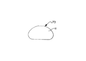
図12は側壁67,68および組み合わされてリンクピン開口21の一部を形成する両リンクピン開口61A,61Bをより明瞭に示す図10のアウターロッカーアーム22の平面図である。図13はロッカーアームアセンブリ14が作動モードである時にエンジンポペット弁6に接触してカムシャフト4およびインナーロッカーアーム18により与えられる動作をエンジンポペット弁6へ伝達するバルブ係合面22Cをより明瞭に示す図11のアターロッカーアーム22の端面図である。プリロードアジャスタ31(図5および図13参照)の支持部69を与える側壁68の形成方法も示されている。図14はリンクピン11がプランジャ30に接触してピボットするピボット部71を示すリンクピン11の断面図である。図15はインナーロッカーアーム18のサドル部50がリンクピン11の支持面73にピボットすることができる半円形を示すリンクピン11の端面図である。
【0034】
次に図16を参照して、本発明の別の実施の形態の断面図を示す。アクチュエータアセンブリ16’はデュアルアームベルクランク74に抗して作動しプランジャ45’はピン76にピボットするベルクランク74の第1アーム72に押し当たり第2アーム70はロッカーアームアセンブリ14’のラッチ部材28’の接触パッド48’と接触する。ラッチスプリング29はラッチ部材28’の接触パッド48’とアウターロッカーアーム22間で圧縮される。
【0035】
アクチュエータアセンブリ16’はケース15’およびコイル23’を有するソレノイドからなりコイル23’はコントロールユニット51により電気的に励起されてステータ27’内に電磁界を生成しそれによりアーマチュア35’が吸着されてアクチュエータスプリング44’はプランジャ45’に取り付けられたリテーナ47’に対して圧縮される。プランジャ45’はアーマチュア35’にスライド可能に接続されている。コイル23’が励起されると、プランジャ45’は第1アーム72に対して下向きに押し進められ第1アーム72は移動して、ベルクランク70を押し進めるようにプリロードされている、リターンスプリング78を時計回りにさらに圧縮して第1アーム72とプランジャ45’間の接触を維持する。ベルクランク70の第2アーム74は接触パッド48’と接触してアクチュエータアセンブリ16’が励起されてロッカーアームアセンブリ14’を非作動モードへシフトする時にラッチ部材28’を右方へ押し進める。
【0036】
次に図17を参照して、本発明のソレノイドアクチュエータアセンブリ15’の部分底面図を示す。ベルクランク70はソレノイドアクチュエータアセンブリ15’のケース15’と係合するピン76に回転支持されている。アクチュエータスプリング44’はプランジャ45’続いてベルクランク70に押し当たる。リターンスプリング78は図示されていない。ソレノイドケース15’は円形断面として図示されているが、ソレノイド技術で周知の任意の形状を利用することができる。
【0037】
【発明の効果】
以上述べたように本発明は、エンジンバルブを作動状態から非作動状態、又はその逆のシフトを行なうために必要な電磁力が低い電磁アクチュエータ機構を提供し、更にこのアクチュエータ機構をエンジンの回転と同期させることなく起動することができるという効果を有する。
【0038】
図面および前記説明により本発明を詳細に説明してきたが、それは説明用であって制約的意味合いは無く、好ましい実施例を示したにすぎず発明の精神内に入る変更および修正は全て発明の範囲内に入り特許請求の範囲によってのみ制限されることを理解できるであろう。
【0039】
関連出願
本出願は03/28/95に出願されたUSSN:08/412,474“バルブ制御システム”および05/26/95に出願されたUSSN:08/452,232“多ロッカーアームバルブ制御システム”および10/06/95に出願されたUSSN:08/540,280“ラッチ可能なロッカーアームを使用するエンジンバルブ制御システム”に関連しており本出願と同じ譲受人であるイートン社が譲り受けている。
【図面の簡単な説明】
【図1】エンジンバルブ列内に取り付けられた本発明のエンジンポペット弁の断面図。
【図2】本発明のソレノイドアクチュエータの部分断面図。
【図3】ソレノイドが起動されラッチ可能なロッカーアームが作動可能モードである本発明のエンジンポペット弁制御システムの断面図。
【図4】ソレノイドが起動されラッチ可能なロッカーアームが作動不能モードである本発明のエンジンポペット弁制御システムの断面図。
【図5】本発明のロッカーアームアセンブリの部分斜視図。
【図6】本発明のロッカーアームアセンブリの平面図。
【図7】本発明のロッカーアームアセンブリの側面図。
【図8】本発明のアウターロッカーアームアセンブリの正面図。
【図9】図8の9−9線に沿ったアウターロッカーアームの断面図。
【図10】図8の10−10線に沿ったアウターロッカーアームの断面図。
【図11】本発明のインナーロッカーアームの立面図。
【図12】図11のインナーロッカーアームの平面図。
【図13】図11のインナーロッカーアームの端面図。
【図14】本発明のリンクピンの断面図。
【図15】図14のリンクピンの端面図。
【図16】本発明の別の実施の形態の断面図。
【図17】図16のリンクピンの端面図。
【符号の説明】
1 エンジンポペット弁制御システム
4 カムシャフト
5 ラッシュアジャスタ
6 エンジンポペット弁
7 バルブスプリング
8 バルブカバー
10 エンジンシリンダヘッド
14,14’ ロッカーアームアセンブリ
15,15’ ソレノイドハウジング
16,16’ アクチュエータアセンブリ
17 アクチュエータアーム
18 インナーロッカーアーム
20 カムローブ
22 アウターロッカーアーム
23,23’ コイル
24,25 ローラフォロアー
26 バイアススプリング
27,27’ ステータ
28,28’ ラッチ部材
29 ラッチスプリング
30,45,45’ プランジャ
31 プリロードアジャスタ
32 本体
33 ストップピン
35,35’ アーマチュア
36 案内ハウジング
37 アームピン
39 アームスプリング
40 インナーハウジング
41 接触板
42 アウターハウジング
43,78 リターンスプリング
44,44’ ソレノイドスプリング
47,47’ カラー
48,48’ 接触パッド
49 オイルドレーン
50 サドル部
51 コントロールユニット
52 ウェッブ部
53,54,67,68 側壁
57 スプリングサポート
58 端部
70,72 アーム
74 ベルクランク
76 ピン[0001]
BACKGROUND OF THE INVENTION
The present invention relates to a valve operating apparatus for an internal combustion engine, and more particularly to an apparatus for operating or not operating an engine valve in accordance with an excited state of an electromagnetic actuator.
[0002]
[Prior art]
Intake valve and / or Also Select exhaust valve selectively Product Move or select Choice With lift profile Product Variable valve control systems for multi-valve engines that can be moved are known in the prior art. Examples are shown in U.S. Pat. Nos. 4,151,817 and 4,203,397. , The disclosure of which is incorporated herein by reference. U.S. Pat. No. 4,151,817 connects a primary rocker arm portion engaged with a first cam, a secondary rocker arm portion engaged with a second cam, and a primary and secondary rocker arm portion. Means to do The Disclosure Shi ing. Patent No. 4,203,397 is an engine poppet valve Selectively engaging and disengaging the valve using a latch mechanism The valve Connected to the rest of the gear Or disconnect and thereby poppet valve Actuating or stationary Shi Device to leave The Disclosure Shi ing.
[0003]
[Problems to be solved by the invention]
Traditional Engagement Possible rocker arm mechanisms , This mechanism But Shift from working to non-working or vice versa Be done The starting power at the time is not low. Solenoid actuator Is Prior art this Used for mechanism Is Then, some kind of motion amplification mechanism such as bell crank Engagement To activate the rocker arm possible big Power The Also Throw . Especially when installed, only low levels of electromagnetic force are required to shift the engine valve from an active state to a non-operating state or vice versa without the need for a synchronization system for timing and timing the engine. do not do Engagement It would be desirable to provide a possible rocker arm.
[0004]
[Means for Solving the Problems]
In accordance with the principles of the present invention, Engagement Necessary to actuate a possible rocker arm (thus stopping the engine valve) Product Powering electromagnetic actuator When An actuator linkage is disclosed. solenoid But Plunger biased by a spring The On the pivot actuator arm biased by the spring versus Then press Guess , Pivot actuator arm Makes contact with the latch member biased by the spring and displaces it to separate the outer rocker arm from the inner rocker arm. Pivot actuator arm only when the contact pad of the latch member is moved to an engageable position and when the rocker arm is on the camshaft lobe The Deactivate engine valve Make Move to position To let it can. However, according to the present invention, the actuator spring that contacts the plunger of the solenoid actuator Is Compressed when the actuator arm is immovable Is The , Limit the force transmitted to the actuator arm , Plunger can contact solenoid stator whenever solenoid coil is energized You The Actuator arm can move freely on its pivot When The plunger is in contact with the actuator arm Actuator arm Rotate to engage latch member. As the engine valve closes, the latch member Is loaded The internal spring is compressed in the actuator arm. When the rocker arm is opposed to the camshaft base circle, the latch member Against load Without Become , A preloaded spring acting in the actuator arm causes the pivot actuator arm to move the latch member to a position where it separates the inner and outer rocker arms to stop the operation of the engine valve. Latch member is loaded when engine valve is closed Be put on If this condition continues, the spring in the actuator arm is compressed. , Latch member What As soon as there is no load, the latch member is moved to the non-actuated position. To move Preload. in this way According to the invention If The actuator can be excited at any time regardless of the position of the engine camshaft using a relatively low power electromagnetic actuator.
[0005]
Four separate and different springs are used for electromagnetic actuators and actuator linkages, and two are Element Used to generate force to return , Two Product Used to transmit power.
[0006]
In another example, the bell crank is moved to a normal position by an electromagnetic actuator. As in the previous example, the electromagnetic actuator resists the spring. Operates, It includes a plunger that allows the plunger to contact the stator whenever the solenoid coil is energized. When the bell crank is closed each A force is applied to the latch member to displace it, and the inner and outer rocker arms are separated to disable the engine valve.
[0007]
One feature of the present invention is a relatively low power solenoid having a spring connecting the armature to the plunger and a linkage mechanism that can start and stop the engine valve on a rocker arm that can be engaged with a reduced level of starting force. Is to provide. Another feature of the present invention is to provide an electromagnetic actuator capable of bringing the armature into contact with the stator while spring biasing the plunger. Another feature of the present invention is that the actuator can be excited at any time without being synchronized with engine rotation. Another feature of the present invention is the provision of a linkage between the rocker arm engageable with the actuator, including a pivot telescopic actuator arm containing a compression spring in contact with the engageable rocker arm. Another feature of the present invention is the provision of a linkage mechanism between the plunger and the solenoid armature between the rocker arm that can be engaged with the actuator, including a link mechanism including an actuator spring combined with a pivotable telescopic actuator arm. Another feature of the present invention is that a linkage including a pivot telescopic actuator arm incorporating an actuator spring and a return spring is provided between the rocker arm engageable with the solenoid. Another feature of the present invention is that a linkage including a pivot bell crank is provided between the rocker arm engageable with the actuator to contact the solenoid plunger with one arm and the latch member with the second arm. . Another feature of the present invention is that an actuator spring disposed between the armature and the plunger includes a link mechanism including a pivot bell crank that contacts the latch member against the bell crank return spring by one arm and compresses the latch spring. Between the solenoid and the plunger.
[0008]
Yet another feature of the present invention includes a pivot bell crank in which a solenoid plunger having a solenoid spring and a solenoid return spring is brought into contact with one arm and an engaging rocker arm fitting member is brought into contact with a second arm. A link mechanism is provided between rocker arms that can be engaged with the solenoid.
[0009]
DETAILED DESCRIPTION OF THE INVENTION
In order to facilitate understanding of the principles of the present invention, specific terms will be used with reference to the drawings. However, this does not limit the scope of the invention, and those skilled in the art will envision various changes and modifications to the illustrated apparatus and various applications of the principles of the invention.
[0010]
In the following description, terminology having no restrictive meaning is used for reference. The terms “right” and “left” refer to the direction on the drawing that uses the terminology associated therewith. The terms “inward” and “outward” refer to directions toward and away from the geometric center of the device, respectively. The terms “upward” and “downward” refer to the direction on the drawing that uses the terminology associated therewith. All of the above terms include ordinary derivatives and synonyms.
[0011]
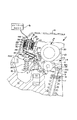
Referring now to FIG. 1, a cross-sectional view of an engine poppet valve control system 1 of the present invention mounted on an internal combustion engine as part of a valve train is shown. A part of an
[0012]
As can be seen from the figure, the engine poppet valve control system 1 is particularly adapted to selectively start and stop the
[0013]
The rocker arm assembly 14 engages with an
[0014]
A
[0015]
The
[0016]
The electromagnetic actuator assembly 16 is shown in a non-excited state in FIG. 1 so that the
[0017]
If the clamping force generated from the inner and
[0018]
The
[0019]
FIG. 1 shows the valve control system 1 in a non-actuated position, in which the actuator assembly 16 has not been excited by the
[0020]
The
[0021]
The
[0022]
The
[0023]
Next, referring to FIG. 3, a sectional view of the valve control system 1 of the present invention is shown. The actuator assembly 16 is excited by the
[0024]
Referring now to FIG. 4, a cross-sectional view of the valve control system 1 of the present invention is shown and the rocker arm assembly 14 is in an inoperative mode.
[0025]
Next, the operation of the rocker arm assembly 14 will be described in detail with reference to FIGS. 5, 6 and 7. The perspective view of the rocker arm assembly 14 shown in FIG. 5 shows the
[0026]
The link pin 11 (see FIG. 1) allows the inner and
[0027]
The
[0028]
Referring now to FIG. 7, a cross-sectional view of the rocker arm assembly 14 of FIG. 6 is shown. The link pin 11 (see FIG. 5) passes through the link pin opening 21 through which the
[0029]
In summary, FIGS. 6 and 7 show top and side views of the rocker arm assembly 14 of the present invention. The
[0030]
FIG. 8 is an elevational view of the
[0031]
10 is a cross-sectional view taken along line 10-10 of the
[0032]
11-13, various views of the
[0033]
FIG. 12 is a plan view of the
[0034]
Referring now to FIG. 16, a cross-sectional view of another embodiment of the present invention is shown. Actuator assembly 16 'operates against dual arm bell crank 74 and plunger 45' presses against first arm 72 of bell crank 74 pivoting on
[0035]
The actuator assembly 16 ′ is composed of a solenoid having a case 15 ′ and a
[0036]
Referring now to FIG. 17, a partial bottom view of the solenoid actuator assembly 15 ′ of the present invention is shown. The
[0037]
【The invention's effect】
As described above, the present invention provides an electromagnetic actuator mechanism that requires a low electromagnetic force to shift the engine valve from the operating state to the non-operating state, or vice versa. It has the effect that it can start without synchronizing.
[0038]
While the invention has been described in detail with reference to the drawings and foregoing description, it is to be understood that it is illustrative and not restrictive and that only preferred embodiments have been shown and all changes and modifications that come within the spirit of the invention are within the scope of the invention. It will be understood that this is limited only by the scope of the claims.
[0039]
Related applications
USSN 08 / 412,474 “Valve Control System” filed on 03/28/95 and USSN 08 / 452,232 “Multi Rocker Arm Valve Control System” filed on 05/26/95 and USSN 08 / 540,280, filed 10/06/95, assigned to Eaton, Inc., the same assignee as the present application, related to "Engine Valve Control System Using Latchable Rocker Arm".
[Brief description of the drawings]
FIG. 1 is a cross-sectional view of an engine poppet valve of the present invention installed in an engine valve train.
FIG. 2 is a partial cross-sectional view of the solenoid actuator of the present invention.
FIG. 3 is a cross-sectional view of the engine poppet valve control system of the present invention in which the solenoid is activated and the latchable rocker arm is in an operable mode.
FIG. 4 is a cross-sectional view of the engine poppet valve control system of the present invention in which the solenoid is activated and the latchable rocker arm is in an inoperative mode.
FIG. 5 is a partial perspective view of the rocker arm assembly of the present invention.
FIG. 6 is a plan view of the rocker arm assembly of the present invention.
FIG. 7 is a side view of the rocker arm assembly of the present invention.
FIG. 8 is a front view of the outer rocker arm assembly of the present invention.
FIG. 9 is a cross-sectional view of the outer rocker arm taken along line 9-9 of FIG.
10 is a cross-sectional view of the outer rocker arm taken along the line 10-10 in FIG.
FIG. 11 is an elevational view of the inner rocker arm of the present invention.
12 is a plan view of the inner rocker arm of FIG. 11. FIG.
13 is an end view of the inner rocker arm of FIG.
FIG. 14 is a cross-sectional view of the link pin of the present invention.
15 is an end view of the link pin of FIG. 14;
FIG. 16 is a cross-sectional view of another embodiment of the present invention.
17 is an end view of the link pin of FIG.
[Explanation of symbols]
1 Engine poppet valve control system
4 Camshaft
5 Rush adjusters
6 Engine poppet valve
7 Valve spring
8 Valve cover
10 Engine cylinder head
14, 14 'rocker arm assembly
15,15 'Solenoid housing
16, 16 'Actuator assembly
17 Actuator arm
18 Inner rocker arm
20 Cam Robe
22 Outer rocker arm
23, 23 'coil
24, 25 Roller Followers
26 Bias spring
27, 27 'stator
28, 28 'latch member
29 Latch spring
30, 45, 45 'Plunger
31 Preload adjuster
32 body
33 Stop pin
35,35 'Armature
36 Guide housing
37 Arm pin
39 Arm Spring
40 Inner housing
41 Contact plate
42 Outer housing
43, 78 Return spring
44, 44 'Solenoid spring
47,47 'color
48,48 'contact pads
49 Oil drain
50 saddle club
51 Control unit
52 Web Club
53, 54, 67, 68 Side wall
57 Spring support
58 end
70, 72 arms
74 Bell Crank
76 pins
Claims (13)
前記プランジャ(30)上でピボット運動するリンクピン(11)と、
前記リンクピン(11)上に回転不能に支持され、前記エンジンポペット弁(6)と係合可能なアウターロッカーアーム(22)と、
前記リンクピン(11)に回転可能に接触するサドル部(50)を有し、前記アウターロッカーアーム(22)に対して回転可能であり、かつ前記カムローブ(20)と係合するインナーロッカーアーム(18)と、
前記インナーロッカーアーム(18)と前記アウターロッカーアーム(22)に接触して、前記アウターロッカーアーム(22)を前記ポペット弁(6)と係合させ、かつ、前記インナーロッカーアーム(18)を前記カムローブ(20)に当接させるバイアススプリング(26)と、
前記アウターロッカーアーム(22)の上を第1の位置と第2の位置の間でスライド可能なラッチ部材(28)であって、前記ポペット弁(6)に隣接する、前記アウターロッカーアーム(22)の一端付近から前記アウターロッカーアーム(22)に沿って前記リンクピン(11)へ向かって延びており、該ラッチ部材(28)が前記第1の位置にあるとき、前記カムローブ(20)によって前記インナーロッカーアーム(18)へ加えられた力に応答して前記リンクピン(11)と一緒にピボット点の周りに回転するように前記インナーロッカーアーム(18)と前記アウターロッカーアーム(22)を選択的に連結し、該ラッチ部材(28)が前記第2の位置にあるとき、前記インナーアーム(18)と前記アウターロッカーアーム(22)を、別々に回転するように選択的に連結解除する、スライド可能なラッチ部材(28)と、
力および変位を加える作動手段(16)と、
第1の端部でピボット支持され、前記作動手段(16)によって発生した力が加わると第2の端部において前記ラッチ部材(28)に接触するアクチュエータアーム(17)であって、長さが可変であり、かつその上に作用して前記アクチュエータアーム(17)を延伸位置へ付勢するアームスプリング(39)を有するアクチュエータアーム(17)と
を有する内燃機関のバルブ制御システム。A valve control system for an internal combustion engine having a cylinder head (10), an engine poppet valve (6), and a camshaft (4) and having a cam lobe (20) formed on the camshaft (4). 1) a lash adjuster (5) having a plunger (30) and mounted on the cylinder head (10);
A link pin (11) pivoting on the plunger (30);
An outer rocker arm (22) supported non-rotatably on the link pin (11) and engageable with the engine poppet valve (6);
An inner rocker arm (50) having a saddle portion (50) rotatably contacting the link pin (11), rotatable relative to the outer rocker arm (22), and engaging the cam lobe (20) 18) and
Contacting the inner rocker arm (18) and the outer rocker arm (22), engaging the outer rocker arm (22) with the poppet valve (6), and moving the inner rocker arm (18) to the A bias spring (26) to be brought into contact with the cam lobe (20);
A latch member (28) slidable on the outer rocker arm (22) between a first position and a second position, the outer rocker arm (22) adjacent to the poppet valve (6) ) From one end of the outer rocker arm (22) toward the link pin (11), and when the latch member (28) is in the first position, the cam lobe (20) In response to a force applied to the inner rocker arm (18), the inner rocker arm (18) and the outer rocker arm (22) are rotated together with the link pin (11) around a pivot point. selectively connecting, when said latch member (28) is in said second position, the said inner arm (18) outer rocker arm ( 2), and selectively uncoupling in rotation separately slidable latch member (28),
Actuating means (16) for applying force and displacement;
An actuator arm (17) pivotally supported at a first end and contacting the latch member (28) at a second end when a force generated by the actuating means (16) is applied, the actuator arm (17) having a length An internal combustion engine valve control system comprising: an actuator arm (17) having an arm spring (39) that is variable and acts thereon to bias the actuator arm (17) to an extended position.
プランジャ(30)を有し、前記シリンダヘッド(10)上に取付けられたラッシュアジャスタ(5)と、
前記プランジャ(30)上にピボット支持されたリンクピン(11)と、
前記リンクピン(11)上に回転不能に支持され、前記エンジンポペット弁(6)と係合可能なアウターロッカーアーム(22)と、
前記リンクピン(11)に回転可能に接触するサドル部(50)を有し、前記アウターロッカーアーム(22)に対して回転可能であり、かつ前記カムローブ(20)と係合するインナーロッカーアーム(18)と、
前記インナーロッカーアーム(18)と前記アウターロッカーアーム(22)に接触して、前記アウターロッカーアーム(22)を前記ポペット弁(6)と係合させ、かつ、前記インナーロッカーアーム(18)を前記カムローブ(20)に当接させるバイアススプリング(26)と、
前記アウターロッカーアーム(22)の上を第1の位置と第2の位置の間でスライド可能なラッチ部材(28)であって、前記ポペット弁(6)に隣接する、前記アウターロッカーアーム(22)の一端付近から前記アウターロッカーアーム(22)に沿って前記リンクピン(11)へ向かって延びており、該ラッチ部材(28)が前記第1の位置にあるとき、前記カムローブ(20)によって前記インナーロッカーアーム(18)へ加えられた力に応答して前記リンクピン(11)と一緒にピボット点の周りに回転するように前記インナーロッカーアーム(18)と前記アウターロッカーアーム(22)を選択的に連結し、該ラッチ部材(28)が前記第2の位置にあるとき、前記インナーアーム(18)と前記アウターロッカーアーム(22)を、別々に回転するように選択的に連結解除する、スライド可能なラッチ部材(28)と、
力および変位を加える作動手段(16')と、
前記作動手段(16')に接触する第1のアーム(72)と前記ラッチ部材(28)に接触する第2のアーム(70)を有し、これら第1、第2のアーム(72,70)間にピボット支持されたベルクランク(74)と
を有し、
前記作動手段(16 ' )がコントロールユニット(51)に電気的に接続されたソレノイドであり、前記コントロールユニット(51)は前記ソレノイド内のコイル(23 ' )へ電流を供給して、ステータ(27 ' )が前記コイル(23 ' )によって磁化された時にア ーマチュア(35 ' )を磁気的に吸引させ前記ステータ(27 ' )へ向けて動かし、
前記アーマチュア(35 ' )にスライド可能に取り付けられたプランジャ(45 ' )と、
前記アーマチュア(35 ' )に接触する第1の端部および前記プランジャ(45 ' )に接触する第2の端部を有する圧縮アーマチュアスプリング(44 ' )と
を有する
する内燃機関のバルブ制御システム。A valve control system for an internal combustion engine having a cylinder head (10), an engine poppet valve (6), and a camshaft (4) and having a cam lobe (20) formed on the camshaft (4). 17)
A lash adjuster (5) having a plunger (30) and mounted on the cylinder head (10);
A link pin (11) pivotally supported on the plunger (30);
An outer rocker arm (22) supported non-rotatably on the link pin (11) and engageable with the engine poppet valve (6);
An inner rocker arm (50) having a saddle portion (50) rotatably contacting the link pin (11), rotatable relative to the outer rocker arm (22), and engaging the cam lobe (20) 18) and
Contacting the inner rocker arm (18) and the outer rocker arm (22), engaging the outer rocker arm (22) with the poppet valve (6), and moving the inner rocker arm (18) to the A bias spring (26) to be brought into contact with the cam lobe (20);
A latch member (28) slidable on the outer rocker arm (22) between a first position and a second position, the outer rocker arm (22) adjacent to the poppet valve (6) ) From one end of the outer rocker arm (22) toward the link pin (11), and when the latch member (28) is in the first position, the cam lobe (20) In response to a force applied to the inner rocker arm (18), the inner rocker arm (18) and the outer rocker arm (22) are rotated together with the link pin (11) around a pivot point. selectively connecting, when said latch member (28) is in said second position, the said inner arm (18) outer rocker arm ( 2), and selectively uncoupling in rotation separately slidable latch member (28),
Actuating means (16 ') for applying force and displacement;
It has a first arm (72) that contacts the actuating means (16 ′) and a second arm (70) that contacts the latch member (28), and these first and second arms (72, 70). ) have a pivot supported bell crank (74) between,
The actuating means (16 ' ) is a solenoid electrically connected to a control unit (51), and the control unit (51) supplies a current to a coil (23 ' ) in the solenoid, so that a stator (27 ') is the coil (23' move towards) a Machua (35 ') said stator magnetically sucked (27' when it is magnetized by)
A plunger (45 ' ) slidably attached to said armature (35 ' ) ;
'The first end portion and the plunger (45 in contact with the compression armature spring having a second end in contact with) the armature (35)' and (44 ')
A valve control system for an internal combustion engine.
Applications Claiming Priority (2)
| Application Number | Priority Date | Filing Date | Title |
|---|---|---|---|
| US08/622239 | 1996-03-22 | ||
| US08/622,239 US5623897A (en) | 1996-03-22 | 1996-03-22 | Engine valve control system using a latchable rocker arm activated by a solenoid mechanism |
Publications (2)
| Publication Number | Publication Date |
|---|---|
| JPH108929A JPH108929A (en) | 1998-01-13 |
| JP4068176B2 true JP4068176B2 (en) | 2008-03-26 |
Family
ID=24493452
Family Applications (1)
| Application Number | Title | Priority Date | Filing Date |
|---|---|---|---|
| JP06835797A Expired - Lifetime JP4068176B2 (en) | 1996-03-22 | 1997-03-21 | Valve control system for internal twisting engine |
Country Status (4)
| Country | Link |
|---|---|
| US (2) | US5623897A (en) |
| EP (1) | EP0796982B1 (en) |
| JP (1) | JP4068176B2 (en) |
| DE (1) | DE69700480T2 (en) |
Families Citing this family (67)
| Publication number | Priority date | Publication date | Assignee | Title |
|---|---|---|---|---|
| US5987973A (en) * | 1996-07-24 | 1999-11-23 | Honda Giken Kogyo Kabushiki Kaisha | Rotation detecting device of an engine |
| US5690066A (en) | 1996-09-30 | 1997-11-25 | Eaton Corporation | Engine valve control actuator with knee action linkage |
| US5697333A (en) * | 1997-02-20 | 1997-12-16 | Eaton Corporation | Dual lift actuation means |
| DE19801964A1 (en) | 1998-01-21 | 1999-07-22 | Audi Ag | Mechanism to interrupt the force flow between a cam at the camshaft and a valve |
| GB2348246B (en) * | 1999-03-25 | 2002-11-13 | Ricardo Inc | Automotive valve rocker arms |
| US7263956B2 (en) * | 1999-07-01 | 2007-09-04 | Delphi Technologies, Inc. | Valve lifter assembly for selectively deactivating a cylinder |
| US6497207B2 (en) | 2000-10-20 | 2002-12-24 | Delphi Technologies, Inc. | Deactivation roller hydraulic valve lifter |
| US6273040B1 (en) | 2000-05-04 | 2001-08-14 | William P. Curtis | Adjustable overhead rocker cam |
| US6314928B1 (en) * | 2000-12-06 | 2001-11-13 | Ford Global Technologies, Inc. | Rocker arm assembly |
| US6382153B1 (en) * | 2001-04-11 | 2002-05-07 | Delphi Technologies, Inc. | Partial internal guide for curved helical compression spring |
| US6318318B1 (en) * | 2001-05-15 | 2001-11-20 | Ford Global Technologies, Inc. | Rocker arm assembly |
| JP4603213B2 (en) * | 2001-09-03 | 2010-12-22 | 本田技研工業株式会社 | Solenoid valve device |
| DE10146129A1 (en) | 2001-09-19 | 2003-04-03 | Ina Schaeffler Kg | Switching element for a valve train of an internal combustion engine |
| WO2003042506A1 (en) * | 2001-11-14 | 2003-05-22 | Ina-Schaeffler Kg | Rocker arm in a valve train on an internal combustion engine |
| US6591798B2 (en) | 2001-12-17 | 2003-07-15 | Delphi Technologies, Inc. | Variable valve actuation assembly for an internal combustion engine |
| US6499451B1 (en) * | 2001-12-17 | 2002-12-31 | Delphi Technologies, Inc. | Control system for variable activation of intake valves in an internal combustion engine |
| MXPA04006988A (en) | 2002-02-06 | 2005-05-27 | Ina Schaeffler Kg | Switch element for valve actuation in an internal combustion engine. |
| US6532920B1 (en) * | 2002-02-08 | 2003-03-18 | Ford Global Technologies, Inc. | Multipositional lift rocker arm assembly |
| US7007643B2 (en) | 2002-12-30 | 2006-03-07 | Caterpillar Inc. | Engine valve actuation system |
| US6971349B2 (en) * | 2002-08-22 | 2005-12-06 | Ford Global Technologies, Llc | Integrated solenoid board and cam ladder |
| US6805083B2 (en) * | 2002-10-10 | 2004-10-19 | Ford Global Technologies, Llc | Cam cover gasket |
| US7140333B2 (en) * | 2002-11-12 | 2006-11-28 | Volvo Lastvagnar Ab | Apparatus for an internal combustion engine |
| DE10318295A1 (en) * | 2003-04-23 | 2004-11-11 | Ina-Schaeffler Kg | Drag lever of a valve train of an internal combustion engine |
| US6935295B2 (en) * | 2003-09-24 | 2005-08-30 | General Motors Corporation | Combustion-assisted engine start/stop operation with cylinder/valve deactivation |
| US7677213B2 (en) * | 2005-08-04 | 2010-03-16 | Timken Us Llc | Deactivating roller finger follower |
| DE102005048984A1 (en) * | 2005-10-13 | 2007-04-19 | Schaeffler Kg | Switchable drag lever |
| DE102006033403A1 (en) * | 2006-07-19 | 2008-01-24 | Mahle International Gmbh | cam drive |
| US7603972B2 (en) * | 2006-10-10 | 2009-10-20 | Hyundai Motor Company | Cylinder deactivation system for vehicle and variable valve lift system using the same |
| DE102008057830A1 (en) | 2007-11-21 | 2009-05-28 | Schaeffler Kg | Switchable plunger |
| US10415439B2 (en) | 2008-07-22 | 2019-09-17 | Eaton Intelligent Power Limited | Development of a switching roller finger follower for cylinder deactivation in internal combustion engines |
| US9938865B2 (en) | 2008-07-22 | 2018-04-10 | Eaton Corporation | Development of a switching roller finger follower for cylinder deactivation in internal combustion engines |
| US20190309663A9 (en) | 2008-07-22 | 2019-10-10 | Eaton Corporation | Development of a switching roller finger follower for cylinder deactivation in internal combustion engines |
| US9016252B2 (en) | 2008-07-22 | 2015-04-28 | Eaton Corporation | System to diagnose variable valve actuation malfunctions by monitoring fluid pressure in a hydraulic lash adjuster gallery |
| US9581058B2 (en) | 2010-08-13 | 2017-02-28 | Eaton Corporation | Development of a switching roller finger follower for cylinder deactivation in internal combustion engines |
| US9291075B2 (en) | 2008-07-22 | 2016-03-22 | Eaton Corporation | System to diagnose variable valve actuation malfunctions by monitoring fluid pressure in a control gallery |
| US8985074B2 (en) | 2010-03-19 | 2015-03-24 | Eaton Corporation | Sensing and control of a variable valve actuation system |
| US8215275B2 (en) * | 2010-08-13 | 2012-07-10 | Eaton Corporation | Single lobe deactivating rocker arm |
| US9708942B2 (en) | 2010-03-19 | 2017-07-18 | Eaton Corporation | Rocker arm assembly and components therefor |
| US9228454B2 (en) | 2010-03-19 | 2016-01-05 | Eaton Coporation | Systems, methods and devices for rocker arm position sensing |
| US9284859B2 (en) | 2010-03-19 | 2016-03-15 | Eaton Corporation | Systems, methods, and devices for valve stem position sensing |
| US10087790B2 (en) | 2009-07-22 | 2018-10-02 | Eaton Corporation | Cylinder head arrangement for variable valve actuation rocker arm assemblies |
| US9194261B2 (en) | 2011-03-18 | 2015-11-24 | Eaton Corporation | Custom VVA rocker arms for left hand and right hand orientations |
| US11181013B2 (en) | 2009-07-22 | 2021-11-23 | Eaton Intelligent Power Limited | Cylinder head arrangement for variable valve actuation rocker arm assemblies |
| US8196556B2 (en) * | 2009-09-17 | 2012-06-12 | Delphi Technologies, Inc. | Apparatus and method for setting mechanical lash in a valve-deactivating hydraulic lash adjuster |
| US9874122B2 (en) | 2010-03-19 | 2018-01-23 | Eaton Corporation | Rocker assembly having improved durability |
| US9885258B2 (en) | 2010-03-19 | 2018-02-06 | Eaton Corporation | Latch interface for a valve actuating device |
| WO2011129836A1 (en) * | 2010-04-16 | 2011-10-20 | International Engine Intellectual Property Company, Llc | Engine braking system using spring loaded valve |
| CN105121090A (en) * | 2014-03-03 | 2015-12-02 | 伊顿公司 | Valve actuating device and method of making same |
| US10180089B2 (en) * | 2014-08-18 | 2019-01-15 | Eaton Intelligent Power Limited | Valvetrain with rocker arm housing magnetically actuated latch |
| EP3183406A4 (en) * | 2014-08-18 | 2018-04-18 | Eaton Corporation | Magnetically latching flux-shifting electromechanical actuator |
| US10781726B2 (en) * | 2015-06-04 | 2020-09-22 | Eaton Intelligent Power Limited | Electrically latching rocker arm assembly having built-in OBD functionality |
| EP3303782B1 (en) * | 2015-06-04 | 2021-01-13 | Eaton Intelligent Power Limited | Electrically latching rocker arm assembly having built-in obd functionality |
| WO2017091799A1 (en) * | 2015-11-25 | 2017-06-01 | Eaton Corporation | Rocker arm assembly having an electrical connection made between abutting surfaces that undergo relative motion |
| US10316709B2 (en) * | 2015-09-21 | 2019-06-11 | Eaton Intelligent Power Limited | Electromechanical valve lash adjuster |
| WO2017091798A1 (en) * | 2015-11-25 | 2017-06-01 | Eaton Corporation | Hydraulic lash adjuster with electromechanical rocker arm latch linkage |
| GB201603344D0 (en) * | 2016-02-26 | 2016-04-13 | Eaton Srl | Actuation apparatus |
| US10961876B2 (en) * | 2016-05-12 | 2021-03-30 | Eaton Intelligent Power Limited | Rocker arm |
| JP6509956B2 (en) * | 2017-06-30 | 2019-05-08 | 本田技研工業株式会社 | Variable valve system |
| GB201712662D0 (en) | 2017-08-07 | 2017-09-20 | Eaton Srl | Actuation apparatus |
| KR101924869B1 (en) * | 2017-08-10 | 2018-12-05 | (주)모토닉 | Variable valve lift actuator of engine |
| DE112018003877T5 (en) * | 2017-08-25 | 2020-04-16 | Eaton Intelligent Power Limited | DEACTIVATING GAME ADJUSTMENT WITH LOWER LIFT WHEN COMBINED WITH A TWO-STAGE VARIABLE VALVE LIFT ROCKER LEVER |
| JP7004152B2 (en) * | 2018-01-12 | 2022-01-21 | トヨタ自動車株式会社 | Valve mechanism |
| JP6969395B2 (en) * | 2018-01-17 | 2021-11-24 | トヨタ自動車株式会社 | Rocker arm |
| GB201803573D0 (en) * | 2018-03-06 | 2018-04-18 | Eaton Intelligent Power Ltd | Actuation apparatus |
| WO2019228670A1 (en) * | 2018-05-30 | 2019-12-05 | Eaton Intelligent Power Limited | Valvetrain with electromechanical latch actuator |
| DE102018116070A1 (en) * | 2018-07-03 | 2020-01-09 | Schaeffler Technologies AG & Co. KG | Module for a variable stroke valve train of an internal combustion engine |
| CN112771250B (en) * | 2018-09-04 | 2024-03-08 | 伊顿智能动力有限公司 | Direct acting solenoid with variable trigger timing for an electromechanical valve train and actuating lever for switching rocker arms |
Family Cites Families (9)
| Publication number | Priority date | Publication date | Assignee | Title |
|---|---|---|---|---|
| DE2753197A1 (en) * | 1976-12-15 | 1978-06-22 | Eaton Corp | VALVE CONTROL DEVICE |
| US4203397A (en) * | 1978-06-14 | 1980-05-20 | Eaton Corporation | Engine valve control mechanism |
| US4768467A (en) * | 1986-01-23 | 1988-09-06 | Fuji Jukogyo Kabushiki Kaisha | Valve operating system for an automotive engine |
| DE4223475A1 (en) * | 1992-07-16 | 1994-01-20 | Audi Ag | Valve actuation mechanism |
| US5445116A (en) * | 1992-12-22 | 1995-08-29 | Unisia Jecs Corporation | Hydraulic variable lift engine valve gear |
| US5544626A (en) * | 1995-03-09 | 1996-08-13 | Ford Motor Company | Finger follower rocker arm with engine valve deactivator |
| US5524580A (en) * | 1995-05-11 | 1996-06-11 | Eaton Corporation | Adjusting mechanism for a valve control system |
| US5529033A (en) * | 1995-05-26 | 1996-06-25 | Eaton Corporation | Multiple rocker arm valve control system |
| US5584267A (en) * | 1995-12-20 | 1996-12-17 | Eaton Corporation | Latchable rocker arm mounting |
-
1996
- 1996-03-22 US US08/622,239 patent/US5623897A/en not_active Expired - Lifetime
- 1996-10-29 US US08/744,723 patent/US5682848A/en not_active Expired - Lifetime
-
1997
- 1997-02-27 EP EP97301308A patent/EP0796982B1/en not_active Expired - Lifetime
- 1997-02-27 DE DE69700480T patent/DE69700480T2/en not_active Expired - Lifetime
- 1997-03-21 JP JP06835797A patent/JP4068176B2/en not_active Expired - Lifetime
Also Published As
| Publication number | Publication date |
|---|---|
| DE69700480D1 (en) | 1999-10-14 |
| US5682848A (en) | 1997-11-04 |
| EP0796982A1 (en) | 1997-09-24 |
| DE69700480T2 (en) | 2000-05-04 |
| EP0796982B1 (en) | 1999-09-08 |
| JPH108929A (en) | 1998-01-13 |
| US5623897A (en) | 1997-04-29 |
Similar Documents
| Publication | Publication Date | Title |
|---|---|---|
| JP4068176B2 (en) | Valve control system for internal twisting engine | |
| US5690066A (en) | Engine valve control actuator with knee action linkage | |
| EP0767296B1 (en) | Engine valve control system using a latchable rocker arm | |
| JP3830197B2 (en) | Valve control system | |
| US6257201B1 (en) | Exhaust brake | |
| KR100306983B1 (en) | Adjusting mechanism for a valve control system | |
| US7565887B2 (en) | Valve actuation device of internal combustion engine | |
| US7600498B2 (en) | Internal combustion engine with gas exchange valve deactivation | |
| US6691657B2 (en) | Two-step finger follower rocker arm | |
| EP3464837B1 (en) | Actuation apparatus | |
| WO2017060496A1 (en) | Rocker arm assembly for an internal combustion engine | |
| JPH08319809A (en) | Valve control system with plurality of locker arm | |
| CN112469887B (en) | Type II valvetrain for enabling variable valve actuation | |
| EP0860588A1 (en) | Dual lift valve actuation means | |
| US6463897B2 (en) | Mechanical assist actuation bracket for deactivation and two-step roller finger followers | |
| US6745733B2 (en) | Actuating system for mode-switching rocker arm device | |
| JPH1068308A (en) | Valve control system | |
| WO2019040860A1 (en) | Lower travel deactivating lash adjuster when combined with two-step variable valve lift rocker arm | |
| EP1568849B1 (en) | Rocker arm assembly for a valve train | |
| WO2022184327A1 (en) | Bidirectional latch pin assembly, switchable rocker arm, and valvetrain assembly | |
| JPS6324124B2 (en) | ||
| JPH0819844B2 (en) | Engine valve drive | |
| JPS63154810A (en) | Valve switching control system for tappet system for multicylinder internal combustion engine | |
| EP3455469A1 (en) | Rocker arm |
Legal Events
| Date | Code | Title | Description |
|---|---|---|---|
| A521 | Written amendment |
Free format text: JAPANESE INTERMEDIATE CODE: A523 Effective date: 20040315 |
|
| A621 | Written request for application examination |
Free format text: JAPANESE INTERMEDIATE CODE: A621 Effective date: 20040315 |
|
| RD03 | Notification of appointment of power of attorney |
Free format text: JAPANESE INTERMEDIATE CODE: A7423 Effective date: 20040315 |
|
| A131 | Notification of reasons for refusal |
Free format text: JAPANESE INTERMEDIATE CODE: A131 Effective date: 20061220 |
|
| A601 | Written request for extension of time |
Free format text: JAPANESE INTERMEDIATE CODE: A601 Effective date: 20070316 |
|
| A602 | Written permission of extension of time |
Free format text: JAPANESE INTERMEDIATE CODE: A602 Effective date: 20070323 |
|
| A521 | Written amendment |
Free format text: JAPANESE INTERMEDIATE CODE: A523 Effective date: 20070619 |
|
| TRDD | Decision of grant or rejection written | ||
| A01 | Written decision to grant a patent or to grant a registration (utility model) |
Free format text: JAPANESE INTERMEDIATE CODE: A01 Effective date: 20071212 |
|
| A61 | First payment of annual fees (during grant procedure) |
Free format text: JAPANESE INTERMEDIATE CODE: A61 Effective date: 20080110 |
|
| FPAY | Renewal fee payment (event date is renewal date of database) |
Free format text: PAYMENT UNTIL: 20110118 Year of fee payment: 3 |
|
| R150 | Certificate of patent or registration of utility model |
Free format text: JAPANESE INTERMEDIATE CODE: R150 |
|
| FPAY | Renewal fee payment (event date is renewal date of database) |
Free format text: PAYMENT UNTIL: 20110118 Year of fee payment: 3 |
|
| FPAY | Renewal fee payment (event date is renewal date of database) |
Free format text: PAYMENT UNTIL: 20120118 Year of fee payment: 4 |
|
| FPAY | Renewal fee payment (event date is renewal date of database) |
Free format text: PAYMENT UNTIL: 20130118 Year of fee payment: 5 |
|
| R250 | Receipt of annual fees |
Free format text: JAPANESE INTERMEDIATE CODE: R250 |
|
| R250 | Receipt of annual fees |
Free format text: JAPANESE INTERMEDIATE CODE: R250 |
|
| R250 | Receipt of annual fees |
Free format text: JAPANESE INTERMEDIATE CODE: R250 |
|
| R250 | Receipt of annual fees |
Free format text: JAPANESE INTERMEDIATE CODE: R250 |
|
| EXPY | Cancellation because of completion of term |