JP4068149B2 - Method for using signals with increased power to determine the location of a mobile subscriber in a CDMA cellular telephone system - Google Patents
Method for using signals with increased power to determine the location of a mobile subscriber in a CDMA cellular telephone system Download PDFInfo
- Publication number
- JP4068149B2 JP4068149B2 JP50091898A JP50091898A JP4068149B2 JP 4068149 B2 JP4068149 B2 JP 4068149B2 JP 50091898 A JP50091898 A JP 50091898A JP 50091898 A JP50091898 A JP 50091898A JP 4068149 B2 JP4068149 B2 JP 4068149B2
- Authority
- JP
- Japan
- Prior art keywords
- mobile station
- signal
- power level
- station
- base station
- Prior art date
- Legal status (The legal status is an assumption and is not a legal conclusion. Google has not performed a legal analysis and makes no representation as to the accuracy of the status listed.)
- Expired - Fee Related
Links
Images


Classifications
-
- H—ELECTRICITY
- H04—ELECTRIC COMMUNICATION TECHNIQUE
- H04W—WIRELESS COMMUNICATION NETWORKS
- H04W64/00—Locating users or terminals or network equipment for network management purposes, e.g. mobility management
-
- H—ELECTRICITY
- H04—ELECTRIC COMMUNICATION TECHNIQUE
- H04B—TRANSMISSION
- H04B17/00—Monitoring; Testing
- H04B17/20—Monitoring; Testing of receivers
- H04B17/27—Monitoring; Testing of receivers for locating or positioning the transmitter
-
- H—ELECTRICITY
- H04—ELECTRIC COMMUNICATION TECHNIQUE
- H04B—TRANSMISSION
- H04B7/00—Radio transmission systems, i.e. using radiation field
- H04B7/24—Radio transmission systems, i.e. using radiation field for communication between two or more posts
- H04B7/26—Radio transmission systems, i.e. using radiation field for communication between two or more posts at least one of which is mobile
- H04B7/2628—Radio transmission systems, i.e. using radiation field for communication between two or more posts at least one of which is mobile using code-division multiple access [CDMA] or spread spectrum multiple access [SSMA]
-
- H—ELECTRICITY
- H04—ELECTRIC COMMUNICATION TECHNIQUE
- H04W—WIRELESS COMMUNICATION NETWORKS
- H04W52/00—Power management, e.g. TPC [Transmission Power Control], power saving or power classes
- H04W52/04—TPC
- H04W52/30—TPC using constraints in the total amount of available transmission power
- H04W52/36—TPC using constraints in the total amount of available transmission power with a discrete range or set of values, e.g. step size, ramping or offsets
- H04W52/362—Aspects of the step size
-
- H—ELECTRICITY
- H04—ELECTRIC COMMUNICATION TECHNIQUE
- H04B—TRANSMISSION
- H04B17/00—Monitoring; Testing
- H04B17/10—Monitoring; Testing of transmitters
- H04B17/101—Monitoring; Testing of transmitters for measurement of specific parameters of the transmitter or components thereof
- H04B17/102—Power radiated at antenna
-
- H—ELECTRICITY
- H04—ELECTRIC COMMUNICATION TECHNIQUE
- H04W—WIRELESS COMMUNICATION NETWORKS
- H04W52/00—Power management, e.g. TPC [Transmission Power Control], power saving or power classes
- H04W52/04—TPC
- H04W52/18—TPC being performed according to specific parameters
- H04W52/28—TPC being performed according to specific parameters using user profile, e.g. mobile speed, priority or network state, e.g. standby, idle or non transmission
- H04W52/283—Power depending on the position of the mobile
Abstract
Description
発明の背景
I.発明の分野
本発明は、概して、セルラ(cellular)電話システムに関する。さらに特定すると、本発明は、セルラ電話システム内の移動加入者の地理的な位置を決定するためのシステムおよび方法に関する。依然としてさらに特定すると、本発明は、符号分割多重アクセス(CDMA)セルラ電話システム内の移動加入者の位置を突き止めるための方法に関する。
II.発明の背景
セルラ電話システム内で動作する移動無線の位置を決定することができるサービスを有するにはいくつかの望ましい理由がある。例えば、このようなポジショニング(positioning)サービスは、緊急発呼者(911)またはセルラシステム内に位置する子供たちの位置を突き止めるために使用できるだろう。代りに、このようなポジショニングサービスは、ディスパッティングまたは集団監視システムの一部として車両の位置を突き止めるために使用できるだろう。また、セルラシステムオペレータは、移動電話の位置に関する正確な知識に基づいてサービスパラメータをカスタム化するために、このようなポジショニングサービスを使用できるだろう。このようなカスタム化は、例えば、移動が限られている顧客にさらに低い費用のサービスを提供することを含むだろう。ポジショニングサービスは、盗まれたセルラ電話の位置を突き止める上でも、セルラサービスの不正な使用を調査するためにも有効だろう。
無線位置決定のための方法は、送信機から受信機へ光の速度で直線で移動すると想定される無線信号の伝搬遅延を測定するための技法を使用する。指向式アンテナによって提供される角度測定と組み合わされた無線遅延測定は、レーダー位置の根本的な原則である。無線定位は、移動車両によって反射される信号に完全に依存するよりむしろ、移動車両中のトランスポンダーの使用によって、多くの場合増加される。
代りに、移動無線の位置を突き止めるためには、いわゆる三辺測量システムを使用してよい。三辺測量システムにおいては、複数の時間遅延測定が、複数の送信機および/または受信機を使用して行われる。ロラン方式は、既知のおよび固定された位置にある基地局から一連の符号化されたパルスを、移動受信機に伝送する定位システムの一例である。移動受信機は、さまざまな送信機からの信号の到達の回数を比較し、位置の双曲線を決定する。同様に、全地球測位システム(GPS)は、24個の地球軌道旋回衛星のセットから伝送を提供する。移動受信機は、衛星の位置および4つまたは5つ以上の衛星から受信される信号間の時間遅延差に関する知識を使用してその位置を決定することができる。
前記例から、無線位置定位システムが2つのタイプ、つまり、GPSのような、移動ユーザーがそれ自体の位置を決定できるようにするタイプと、レーダーシステムのような、もう一方の相手が移動トランスポンダーの位置を決定できるようにするタイプの2つのタイプに分けることができることが理解できる。本出願に開示されるシステムは、レーダーシステムの固定された部分が、システム内に配置される移動無線装置の位置を決定することを希望する第2のタイプである。受動的なレーダーの場合を除き、このようなシステムは、通常、移動無線装置が無線信号を伝送することを要求する。
「二重衛星ナビゲーション方法およびシステム(Dual Satellite Navigation Method and System)」と題する米国特許第5,126,748号は、移動端末が、信号の送受の両方を行い、それによって位置の円形の線を確定する往復トリップ(round trip)タイミング測定を、移動端末が受信機能だけを具備するロラン方式およびGPSシステムに必要とされるより少ない数の送信機サイトを使用して実行できるようにする無線定位の方法を開示する。その他のシステムにおいては、移動端末は、送信機だけを具備することがあり、残りのシステム要素は、方向検出またはさまざまな位置からの信号の複数の受信を実行し、その位置を決定する。この例が、撃墜された航空機の位置を突き止めるためのSARSATシステムである。このシステムにおいては、撃墜された飛行機は、国際遭難周波数121.5 MHz(および273MHz)で信号を伝送する。地球軌道旋回(orbiting)衛星は、その信号を地球端末に中継する。衛星が頭上を通過すると、ドップラーシフトの変化が検出でき、位置の線が決定できる。同じまたは類似した衛星による複数の頭上上空飛行で位置の線のセットを決定することができ、その交差が、撃墜された航空機の位置を決定する。
直接シーケンススペクトル拡散信号が、距離測定および位置定位のための有効な特性を有することは長く知られている。もっとも早期のスペクトル拡散防害対抗軍事通信システムのいくつかは、正確な距離測定機能を含んでいた。言うまでもなく、GPSは、直接シーケンススペクトル拡散波形の使用に基づいている。GPSでは、ユーザーの受信機は、時間差測定を、視野内の4つまたは5つ以上の衛星から受信されている信号で行うことによって、四次元空間−時間でのその位置を決定する。衛星は、大部分の場所での時間の大部分、正確な位置計算を可能にする適切なジオメトリをもって、十分な衛星が視野に入るように、傾斜した12時間軌道に配置され、並べられる。GPSシステムは、ナビゲーション端末に、位置計算に必要とされる現在の衛星の天体暦情報を知らせる。
電子工業会(EIA)と共同して電気通信産業界協会(Telecommunications Industry Association)(TIA)は、「二重モード広帯域スペクトル拡散セルラシステム用移動局−基地局互換性規格(Mobile Station-Base Station Compatibility Standard for Dual-Mode Wideband Spread Spectrum Cellular System)」と題し、TIA/EIA/IS−95−A、1995年5月(これ以降「IS−95規格」)と呼ばれる暫定規格を作成し、公表した。IS−95規格は、GPS衛星ダウンリンク信号を使用してセルラシステム内の全セル(cell)の伝送を同期し、ルビジウムクロックを更新する符号分割多重アクセス(CDMA)セルラシステムを支援する。したがって、IS−95 CDMAシステムにおいては、タイミングは、GPSシステムから直接セルラシステムに転送される。
IS−95 CDMAシステムは、システム内の3つ(または4つ以上の)基地局が、移動局の信号のタイミング測定を行うことができるならば、三次元空間−時間(二次元ポジショニングを加えた時間)での移動局の位置を決定することができる。ただし、パワー(power)制御を使用する結果、システム内の3つ(または4つ以上)の基地局は、多くの場合、移動局の信号のタイミング測定を行うことができない可能性がある。この点で、各移動送信機パワーは、最良に配置される基地局と通信するために必要な最小パワーだけが使用されるように、非常に注意深く制御される。この特徴は、CDMAによる高いシステム容量の達成にとって主要である。これがポジショニングに関して引き起こす問題とは、移動機(mobile)が1つの基地局に近づいてくると、それが、もっとも近い基地局でちょうど適当なEb/Noを達成できるようにその送信機パワーを削減するだろうという点である。この結果、近隣の基地局でのさらに低い、おそらくはるかに低い、Eb/Noが生じ、多くの場合、移動機の信号をこれらの位置で受信することを困難にする。
IS−95 CDMAシステムにおいては、処理利得は通常21dBである。これは単に最大データ速度(9600 bps)に対するチップレート(chip rate)(1.2288 MHz)の割合である。2つの基地局の間の等距離の点では、両方の基地局に必要とされる送信機パワーはほぼ同じである。受信された移動信号の両方の基地局で結果的に生じるSNRは、優れたタイミング測定を得るのに十分以上であるだろう。しかし、移動局が、別の基地局ではなくある基地局にさらに近い点に移動すると、送信機パワーは削減されるだろう。これによって、さらに離れた基地局では受信されるEb/Noが引き下げられるだろう。測定SNRは、単一ビット時間より長い時間間隔で統合し、効果的に処理利得を高めることによって、上昇することができる。例えば、信号が1つの符号反復つまり32768チップで統合されると、処理利得は45dB(10 * log3278)になるため、SNRは、9600bpsでのSNRに比較して24dB改善される。優れた時間追跡調査のために5dBのSNRが必要とされる場合、遠い基地局での信号は近い基地局より30dB弱くなることがある。このSNRまたはさらに優れたものは、第4パワー伝搬を仮定して、セル領域の約90%で達成できる。したがって、システムの有効範囲領域の90%内では、優れた基地局ジオメトリが正確なポジショニングを得るために使用できるのであれば、基地局は、通常、ポジショニングを支持する時間差測定を行うことができるだろう。(前記に指定された統合時間で)基地局間の時間差測定が使用できないセル領域の10%は、最大セル半径の約30%まで伸びる(out to)セル領域の中心に対応する。したがって、4マイル(2マイルのセル半径)によって区切られる基地局の場合、前記帯域幅前提でポジショニングを実行することができない領域の半径は、約1000メートルである。
ドップラー考慮のために利用される可能性がある統合の時間に関する制限があることが注記される必要がある。例えば、移動機が2つの基地局の間の回線上で60mphで移動している場合、差異のドップラーは約2×10⁻⁷である。これは、800MHzのセルラバンドでの約170Hzに相当する。これは、32768チップでの統合をやや困難にするのに十分なドップラーである。したがって、前記見積は最良のケースとして解釈される必要がある。
したがって、本発明の目的は、移動無線がもっとも近い基地局の近くに配置される場合に、移動無線の位置が決定される、移動無線ポジショニングシステムを提供することである。
本発明のこれらのおよびその他の目的と優位点は、以下の説明およびクレームからさらに完全に明らかになるか、あるいは本発明の実践によって学ばれることがある。
発明の概要
本発明は、複数の基地局を有するセルラ電話システム内で移動局の位置を決定するための方法に向けられている。信号は、移動局から低いパワーレベルで伝送される。それから、信号の強度は、一時的に、低いパワーレベルから高められたパワーレベルに強められ、信号は、この高められたパワーレベルで移動局から一時的に伝送される。信号が高められたパワーレベルで移動局から一時的に伝送されている間、その信号は少なくとも第1位置測定を行うために使用される。移動局の位置は、第1位置測定に従って決定される。
【図面の簡単な説明】
本発明の上記の利点および目的ならびに他の利点および目的を得る方法を理解できるように、簡単に説明された本発明を添付図面に図示されている本発明の特定の実施態様を参照してより特定的に説明する。これらの図面は本発明の典型的な実施態様を示すだけであり、したがってその範囲を制限するものとは考えるべきではなく、本発明および現在理解されているその最良のモードは、以下に添付図面を参照してさらに特定的にそして詳細に説明される。
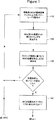
図1および1Aに、移動局が位置決めチャネルに切り替えられて、移動局からのパワー伝送が一時的に増大させて、移動局と隣の基地局との間でタイミングの測定を可能とする、本発明の一つの好ましい実施態様に従った移動無線位置決めシステムの動作を示す。
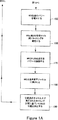
図2および2Aに、移動局からのパワー伝送が一時的に増大させて、移動局と隣の基地局との間でタイミングの測定を可能とする、本発明の一つの好ましい実施態様に従った移動無線位置決めシステムの動作を示す。
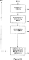
図3に、「送信専用」のスレーブアンテナ(slave antenna)を有する基地局を用いて、移動無線位置を決定する、本発明の一つの好ましい実施態様に従った移動無線位置決めシステムの動作を示す。
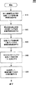
図4に、「受信専用」スレーブアンテナを有する基地局を用いて、移動無線位置を決定する、本発明の一つの好ましい実施態様に従った移動無線位置決めシステムの動作を示す。
図5から7に、たった2つの基地局を用いて、移動局の位置を決定する、本発明の一つの好ましい実施態様に従った移動無線位置決めシステムの動作を示す。
図8に、回転送信用ビームアンテナを有する基地局を用いて、移動無線の位置を決定する、本発明の一つの好ましい実施態様に従った移動無線位置決めシステムを示す。
図9に、回転受信用ビームアンテナを有する基地局を用いて、移動無線の位置を決定する、本発明の一つの好ましい実施態様に従った移動無線位置決めシステムを示す。
図10および10Aに、セルラシステム中のおのおののセルが位置決め専用であって音声通信には利用できないRFチャネルを有する、本発明の一つの好ましい実施態様に従った移動無線位置決めシステムの動作を示す。
図11に、基地局送信機が事前決定された期間中に自身をオフし、これによって、移動局と隣の基地局との間でのタイミング測定を可能とする、本発明の一つの好ましい実施態様に従った移動無線位置決めシステムの動作を示す。
図12に、移動局のパワーを1つのフレームに対して一時的に増大させて、移動局と隣の基地局との間でのタイミング測定を可能とする、本発明の一つの好ましい実施態様に従った移動無線位置決めシステムの動作を示す。
好ましい実施態様の説明
図1から12に、セルラ電話システム中の移動無線の位置決めをする、本発明の好ましい実施態様に従ったシステムを示す。図1から12に示す位置決めシステムはおのおのが、セルラ電話システム中の移動式ユニットと基地局との間の通信のためのスペクトラム拡散変調技法を用いたセルラ電話システムの一部として具体化されるのが好ましい。セルラ電話システム中での通信のためにこのようなスペクトラム拡散変調(またはCDMA)技法を用いる移動無線ユニットおよび基地局を有する例示の電話システムが、「CDMAセルラシステム中で信号波形を発生するシステムと方法」(System and Method for Generating Signal Waveforms in a DCMA Cellular System)という題名の米国特許第5,103,459号および「セルラ電話システム中の多様性受信機」(Diversity Receiver in a Cellular Telephone System)という題名の米国特許第5,109,390号に開示されている。米国特許第5,103,459号および第5,109,390号の内容のすべてを参照してここに組み込む。米国特許第5,103,459号および第5,109,390号に開示されるタイプの移動無線ユニットおよび基地局は以後それぞれCDMA移動局とCDMA基地局と呼ぶ。
ここで図1および1Aを参照すると、CDMA移動局が位置決めチャネルに切り替えられて、CDMA移動局からのパワー伝送を一時的に増大させて、移動局と隣のCDMA基地局との間でのタイミング測定を可能とする、本発明の一つの好ましい実施態様に従った移動無線位置決めシステム100の動作が示されている。位置決めシステム100は、CDMA移動局(または移動無線)がセルラシステム中の1つのまたは複数の基地局と通常のRFトラフィックチャネル(traffic channel)上で音声通信している場合に、ステップ110で最初に呼び出される。発明の背景の項で上述したように、移動局が通常のRFトラフィックチャネル上で動作しているときは、トラフィック容量を高く保つために、そのパワーレベルはできるかぎり最小レベルになるように制御され維持される。この低いパワーレベルは、移動局が最も近い基地局(または最初の基地局)と通常RFトラフィックチャネル上で通信できるように十分低い値である。移動局が最も近い基地局とこのような通信状態にある場合、この最も近い基地局はその送信機と受信機を用いて、無線信号がその最も近い基地局から移動局に伝搬し、またその移動局からその最も近い基地局に帰ってくるに要する時間を表す往復トリップ時間を測定する。より具体的に言うと、基地局の送信機は、CDMA無線信号が基地局から伝送されると伝送クロック同期設定(または相対的な伝送時間)を与える伝送クロックを有する。その上、基地局の受信機は、移動局から受信されて戻ってきたCDMA信号を復調し、また、このような信号が基地局委で受信されたときに関連する受信クロック同期設定(または相対的受信時間)を決定する手段を有する。ステップ110において、送信クロック同期設定と受信クロック同期設定との間の差を比較することによって、基地局は、無線信号が基地局から移動局に伝搬し次に移動局から基地局に戻るまで要する時間を表す往復トリップ時間を測定することができる。この往復トリップ時間測定値に信号伝搬速度(すなわち光速)を乗算することによって、移動局と最も近い基地局との間の相対的な距離を決定することができる。往復トリップ時間測定値によって移動局は、このような相対的距離に等しい半径を有し、最も近い基地局の回りにその中心を持つ円の上に置かれる。
次に、ステップ120において、システムは移動局と隣の基地局(または第2の基地局)との間のタイミングの測定を試みる。ステップ120において、この測定は、移動局が低パワーで通常RFトラフィックチャネル上で動作中に試みられる。ステップ120で実行されるタイミング測定は、移動局と第2の基地局の間での往復トリップ信号伝搬時間測定であってもよい。その代わりに、ステップ120で試みられるタイミング測定は、移動局からの信号がそれぞれ第1と第2の基地局で受信される時間差に対応するようにしてもよい。このような到達時間差に信号伝搬速度(すなわち光速)を乗算することによって、第1と第2の基地局間での移動局の位置の双曲線か、移動局の位置のさらなる円のいずれかが決定される。次に、ステップ130においては、システムは、ステップ110と120で実行されたタイミング測定に基づいて移動局の位置を決定するように試みる。より具体的に言うと、システムは、ステップ110で決定された位置の円と、ステップ120で決定された円(または双曲線)との交点を発見しようと試みる。システムがこのような交点を2つ以上発見した場合、移動局の正確な位置は、複数の移動局の内の1つの移動局のセクターアンテナ(sector antenna)を用いて、セルラシステム中における移動局の真の位置を表す交点を選択することによって決定される。こうする代わりに、システムがこのような交点を2つ以上発見したら、第1と第2の基地局の内のいずれかと第3の基地局との間のさらなる到達時間差を測定して移動局の真の位置を決定してもよい。
例えば、第2の基地局が移動局の信号を適切に受信するに必要な最小パワー未満のパワーレベルで、移動無線局が動作したりしているために、システムがステップ120でタイミングをまったく測定できない場合、処理はステップ140に進み、ここで、移動無線局は通常RFトラフィックチャネルから特殊RF位置決めチャネルに切り替えられる。この特殊RF位置決めチャネルは、音声通信をサポートする能力を有するが、ステップ110から130で使用される通常RFトラフィックチャネルからは分離されている通常CDMAチャネルのことである。これと同じRFチャネルを、CDMAセルラシステム中のすべてのセルにわたるこの特殊RF位置決めチャネルのために用いるのが好ましい。この後で、ステップ150においては、移動局が位置決めチャネル上で動作中に、移動局からの伝送のパワーがその可能な最大パワーレベルにまで増大される。移動局からの伝送がこの増大したパワーレベルで進行中に、ステップ160では移動局と隣の基地局の間でタイミングが測定される。ステップ160で実行されるタイミング測定はステップ120でのタイミング測定と同じであるが、ステップ160では、増大したパワーレベルで移動ユニットから伝送された信号を用いてタイミングが測定されるという点が異なる。ステップ170と180においては、移動局からの伝送のパワーはその通常の低レベルに減少して、通常RFトラフィックチャネルに切り替えられて戻される。移動局がその増大したパワーレベルで動作しているステップ150と170の間の期間は、ステップ160で実行されるタイミング測定が成功裏に完了されるに十分な値であることが望ましいが、この期間は、移動局から伝送される信号中の1音声フレームの期間と同じ短さであってもよい。
最後に、ステップ190において、システムはステップ110と160で実行されたタイミング測定に基づいて移動局の位置を決定する。より具体的に言うと、システムはステップ110で決定された位置の円と、ステップ160で決定された位置の円(または双曲線)との交点を1つ以上発見する。システムが2つ以上の交点を発見した場合、移動局の正確な位置は、複数の基地局の内の1つの基地局のセクターアンテナを用いてセルラシステム中の移動局の真の位置を表す交点を選択することによって決定される。図1と1Aに示すプロセスは周期的に繰り返して、移動局がセルラシステム内を移動するにつれて移動局に関する現行の位置情報を維持するようにするのが好ましい。このプロセスは、例えば移動局によって伝送される信号内の100音声フレームにつき1つの音声フレームに等しい時間間隔で、またはその代わりに1秒から3秒毎に繰り返すようにしてもよい。
ステップ130と190で実行される位置の計算は1つ以上の基地局内で実行してもよいしセルラシステムの切換センター内で実行してもよいことが当業者には理解されよう。
上記の実施態様では、移動局からの伝送のパワーは最初にステップ150でその可能な限りの最大パワーレベルに増大する。1つの代替実施態様では、移動局のパワーレベルは例えば20dBまで徐々に上昇し、ついには、第2の基地局が、ステップ160で必要とされるタイミング測定を成功裏に実行できるようになる。本発明の本好ましい実施態様では、ステップ140と190でマップ整合(map matching)テーブルを用いて、システムによる位置決定の精度を向上させている。システム100によるタイミング測定は信号伝搬時間(または信号伝搬時間の差)に対応するのが好ましいので、位置決め精度は移動局と基地局との形状が不適切であったり、信号伝搬経路が曲がったりしていると劣化する。マップ整合テーブルは、移動局が公道を走行中の車両内にあると仮定し、このような道路上のさまざまな点における位置計算上の誤差の原因となる基地局の不適切な形状や曲がった伝搬経路を埋め合わせることによって形成される。このようなマップ整合テーブルを開発する好ましい方法の1つは、ある地域をその地域内のさまざまな道路に沿って移動局を駆動することによって調査することである。移動局が駆動されている間に、その地域内のさまざまな位置で上記のタイミング測定を実行する。その上、このようなおのおのの位置で、例えばGPSを用いて移動局の実際の位置を決定し、この実際の位置を、その位置で実行されたタイミング測定の結果と関連してテーブル中にエントリとして記憶する。ステップ110,120および/または160で実行されたタイミング測定は、次に、テーブルに記憶されているタイミング測定結果と比較され、ステップ110,120および/または160で実行されたタイミング測定と最も緊密に整合するタイミング測定を有するエントリがテーブルから選択される。次に、移動局の位置は、このように選択されたエントリのおのおのに対してテーブル内に記憶されている実際の位置間で内挿させることによって決定される。
最後に、システム100は上述したようにスペクトラム拡散すなわちCDMAセルラシステムの一部として具体化されたが、システム100のステップは、例えば時間分割多重アクセス変調システムなどの他の変調システムと関連させて具体化し、これによって、このようなシステム内で動作する移動局の位置を決定するようにしてもよいことが当業者には理解されよう。
ここで図2と2Aを参照すると、移動無線位置決めシステム200の動作が示されているが、ここでは、本発明の一つの好ましい実施態様に従って、移動局からのパワー伝送を一時的に増大させて、移動局と隣の基地局の間でタイミングを測定できるようにしている。システム200は実質的にはシステム100とその機能は同じであるが、システム200においては、第2の隣の基地局でのタイミング測定を可能とするために、移動局は、そのパワーレベルが増大する前に分離した位置決めチャネルに切り替えられたりしないという点が異なる。このようにして、ステップ210,220および230は実質的にステップ110,120および130にそれぞれ対応し、ステップ240,250、260および270は実質的にステップ150,160,170および190にそれぞれ対応する。システム200はシステム100に比較して不利な点を有するが、その理由は、システム200においては、通常RFトラフィックチャネル上で動作している他の移動局は、位置決めされている移動局がそのパワーレベルをステップ240と260の間で増加させるとフレームエラーが発生しかねないからである。しかしながら、CDMAシステムは通常はこのような偶発的なフレームエラーに耐えることができる。
ここで図3を参照すると、ある移動無線位置決めシステム300の動作が示されているが、ここでは、本発明の一つの好ましい実施態様に従って、「伝送専用」スレーブアンテナを有する基地局を用いて、移動無線の位置を決定している。システム300においては、修正型CDMA基地局を通常型CDMAの代わりに用いている。この修正型基地局においては、2つ以上(できれば3つ)の伝送専用のスレーブアンテナが、通常(またはマスター(master))の基地局アンテナに近接して(これの約数100フィート以内に)置かれる。2セクター式CDMA基地局の場合、3つの伝送専用スレーブアンテナを用いるのが好ましいが、この場合、スレーブアンテナはおのおのがこの3つのセクターのそれぞれ別々のセクター内に置かれる。これらのスレーブアンテナはそのおのおのが、CDMA信号を伝送するための関連回路を有し、この関連回路は、マスター基地局アンテナからのCDMA信号の伝送用の信号伝送回路と実質的に類似している。ステップ305,310,315および320において、第1,第2,第3および第4のそれぞれ別々のCDMA信号(そのおのおのが分離した事前割当てウオルシュ符号を有している)はそれぞれ、基地局にある第1,第2および第3のスレーブアンテナならびにマスターアンテナから伝送される。第1,第2,第3および第4の信号は共通のCDMAトラフィックチャネル上で伝送される。第1,第2および第3の信号が別々のセクター内に置かれているスレーブアンテナから伝送される場合、第1,第2および第3の信号はまた、このような信号の伝送元であるセクターに対応した別々のpn符号位相を有する。ステップ325,330,335および340において、ステップ305,310,315および320で伝送されたこれら4つの信号はそれぞれ移動局によって受信される。移動局は、別々のウオルシュ符号および別々のpn符号位相を有する複数の信号を同時に復調して、このような信号のおのおのと関連したクロック同期設定(または相対的受信時間)を決定する手段を有する。ステップ345においては、マスターアンテナとスレーブアンテナから伝送された信号と関連したクロック同期設定同士間の差を比較することによって、移動局は、ステップ305,310,315および320で伝送された信号が移動局によって受信された相対的時間に対応する到達時間の差を計算することができる。最後に、ステップ350において、ステップ305,310,315および320で伝送された信号の到達時間の差を用いて、位置の少なくとも2つの双曲線を計算する。次にシステムは位置のこれらの双曲線同士の1つ以上の交点を識別する。システムがこのような交点を2つ以上発見した場合は、移動局の正確な位置は、基地局のセクターアンテナを用いて、セルラシステム内の移動局の真の位置を表す交点を選択することによって決定してもよい。
ステップ350でなされる位置計算は、移動局、基地局およびシステムの切換センターのいずれで実行してもよい。この計算を移動局内で実行する場合、基地局のマスターアンテナおよびスレーブアンテナの座標は、移動局が上記の位置の双曲線を決定できるようになる前に移動局に伝送しなければならない。そうする代わりに、計算を基地局内で実行する場合、移動ユニットによって測定された到達時間差は、位置計算が実行可能となる前に基地局に伝送する必要がある。システム300のこの好ましい実施態様では、(上記の)マップ整合テーブルをステップ350で用いて、システムによる位置決定の精度を向上させる。
ここで図4を参照すると、ある移動無線位置決めシステム400の動作が示されているが、ここでは、本発明の一つの好ましい実施態様に従って、「受信専用」スレーブアンテナを有する基地局を用いて、移動無線位置を決定する。システム400では、修正型CDMA基地局を通常CDMA基地局の代わりに用いている。この修正型基地局においては、2つ以上の受信専用のスレーブアンテナが通常の(またはマスター)基地局アンテナに近接して(その数100フィート以内に)置かれている。スレーブアンテナはおのおのが、CDMA信号を受信するための関連の回路を有しているが、この関連回路は、マスター基地局アンテナでCDMA信号を受信するために用いられる信号受信回路に実質的に類似している。セクター化された基地局の場合、受信専用のスレーブアンテナをおのおののセクター内に置くのが好ましい。このようにして、3セクター式のCDMA基地局の場合、3つの受信専用スレーブアンテナを、そのおのおのが3つのセクターのそれぞれ別々のセクター内に置かれるように使用するのが好ましい。以下に述べる位置決め機能を実行するほかにも、これらの受信専用スレーブアンテナはまた基地局でのダイバーシチアンテナとして用いることもできる。
ステップ410においては、移動局が通常RFトラフィックチャネルを用いてCDMA音声通信信号を伝送する。ステップ420,430および440においては、ステップ410で伝送された信号が、それぞれ第1および第2のスレーブアンテナならびにマスターアンテナによって基地局で受信される。これら2つのスレーブアンテナおよびマスターアンテナはおのおのが、移動局から伝送されたCDMA信号を復調し、信号がこのようなアンテナのおのおのによって受信されたときに関連するクロック同期設定(または相対的受信時間)を決定する手段を有する。ステップ450においては、マスターアンテナおよびスレーブアンテナで受信された信号と関連するクロック同期設定の間の差を比較することによって、基地局は、ステップ410で伝送された信号が基地局でスレーブアンテナとマスターアンテナによって受信された相対的時間に対応する到達時間の差を計算することができる。最後に、ステップ460において、ステップ420,430および440で受信された信号の到達時間差を用いて、位置の2つの双曲線を計算する。次にシステムは、位置のこれらの双曲線同士の交点を1つ以上識別する。システムがこのような交点を2つ以上発見した場合、移動局の正確な位置は、基地局でセクターアンテナを用いてセルラシステム内の移動局の真の位置を表す交点を選択することによって決定し得る。
ステップ460における位置計算は基地局内とセルラシステムの切換センター内のどちらで実行してもよいことが当業者には理解されよう。システム400のこの好ましい実施態様では、(上述の)マップ整合テーブルをステップ450と460で用いて、システムによって実行される位置決定の精度を向上させている。
システム400の1つの代替実施態様では、スレーブアンテナはステップ420と430で信号を受信することができなかったが、この理由は、例えば移動無線局が、スレーブアンテナが移動局の信号を適切に受信するために必要とされる最小パワー未満のパワーレベルで動作中であり、次に、移動局からの伝送のパワーをより高いパワーレベルに一時的に増大させるからである。ある好ましい実施態様では、このより高いパワーレベルは、CDMA基地局内に搭載された閉ループパワー制御システムを用いて達成される。通常は、このパワー制御システムは、マスター基地局アンテナで受信された信号を用いて、移動局のパワーレベルを調節する。しかしながら、スレーブアンテナの内の1つ以上がステップ420および/または430で移動局を受信することができない場合、パワー制御システムはその入力を変更して、スレーブアンテナで受信された最も弱い信号を用いて、移動局のパワーレベルを調節するのが好ましい。この方法によって、移動局からの信号がすべてのスレーブアンテナで受信されるに十分なパワーレベルにまで増大されることが保証される。移動局からの伝送がこの増大されたパワーレベルで実行されている間に、ステップ420,430および440ではタイミング測定が実行される。その後で、移動局からの伝送のパワーは通常の低レベルに減少する。上述したように、移動局がその増大したパワーレベルで動作している期間は、ステップ420,430および440でのタイミング測定が成功裏に完了されるに十分な長さであることが好ましいが、この期間は移動局から伝送される信号中の1音声フレームの期間と同じ値であってもよい。
図3と4に示すプロセスは周期的に繰り返して、移動局がそのセルラシステム内で移動するに連れての現行位置の情報を維持するようにするのが好ましい。個々のプロセスを、例えば移動局から伝送される信号中の100音声フレーム毎の1つに等しい時間間隔で、またはそのかわりに、1秒から3秒毎に繰り返してもよい。最後に、上述したシステム300と400は、スペクトラム拡散すなわちCDMAセルラシステムの一部として具体化されたが、これらのシステムのステップは、このようなシステム内で動作している移動局の位置を決定するために、例えば時間分割多重アクセス変調システムなどの他の変調システムと関連して具体化してもよいことが当業者には理解されよう。
ここで図5を参照すると、移動無線位置決めシステム500の動作が示されているが、ここでは、本発明の一つの好ましい実施態様に従って、たった2つの基地局を用いて、移動局の位置を決定している。ステップ510と520では、第1のウオルシュ符号および第1のpn符号オフセットを有する第1のCDMA信号が第1のCDMA基地局から伝送され、第2の(異なった)ウオルシュ符号および第2の(異なった)pn符号オフセットを有する第2のCDMA信号が第2のCDMA基地局から伝送される。第1と第2の信号は、移動局とそのそれぞれの地域内で通信するためには、第1と第2の基地局で用いられた通常のRFトラフィックチャネル上で伝送されるのが好ましい。ステップ515と520においては、ステップ510と520で伝送されたこれら2つの信号はそれぞれ移動局から受信される。移動局は、別々のウオルシュ符号および別々のpn符号オフセットを有する複数の信号を同時に変調して、このような信号のおおのおのと関連するクロック同期設定(または相対的受信時間)を決定する手段を有する。ステップ530においては、第1と第2の基地局から伝送された信号と関連したクロック同期設定間の差を比較することによって、移動局は、ステップ510と520で2つの信号が移動局によって受信される相対的な時間に対応する到達時間差を計算することができる。この到達時間差によって、移動局は第1と第2の基地局間にある双曲線上に置かれる。次に、ステップ530において、第1の基地局は自分自身と移動局の間で往復トリップタイミング測定を実行する。図1を参照して上述したように、このような往復トリップ時間測定値は、無線信号が第1の局から移動局に伝搬して次にその移動局からその第1の局まで戻って来るに必要な時間を表す。この往復トリップ時間測定値に信号伝搬速度(すなわち光速)を乗算することによって、移動局と第1の基地局間の相対的な距離を決定することができる。このようにして、この往復トリップ時間測定値によって、移動局は、このような相対的距離に等しい半径を有し第1の基地局の回りにその中心を持つ円の上に置かれる。
次に、ステップ550において、システムは、ステップ530と540で実行された測定に基づいて決定された位置の双曲線と円の交点を1つ以上識別する。このような交点はおのおのが、移動局が置かれているかもしれない候補の位置を表す。システムがこのような交点を2つ以上発見した場合は、2つの基地局の内の一方のところにあるセクターアンテナ(またはその代わりにスレーブアンテナのセクターアンテナ)をステップ560で用いて、移動局が置かれている角度セクターを決定する。好ましい実施態様においては、セクターアンテナはその受信地域を3つの120度セクターに分割する。スレーブアンテナがステップ560で使用される場合、このようなセクター間の境界線はシステム内の他のスレーブアンテナを指し示すのが好ましい。最後に、ステップ570において、移動局の位置は、ステップ560で識別されたセクター内に置かれた候補位置を選択することによって決定される。図1から4を参照して上述したように、ステップ550と570で実行された位置計算は、移動局の中または基地局のいずれか1つの中のどちらで実行してもよい。
ここで図6を参照すると、移動無線位置決めシステム600の動作が示されているが、ここでは、本発明の1代替の好ましい実施態様に従って、たった2つの基地局を用いて、移動局の位置を決定している。ステップ610においては、第1の基地局が自分自身と移動局の間で第1の往復トリップタイミング測定を実行している。上述したように、この第1の往復トリップ時間測定によって、移動局は、第1の基地局の回りに中心を持つ第1の円の上に置かれる。次に、ステップ620においては、第2の基地局が自分自身と移動局の間でさらなる往復トリップタイミング測定を実行する。この往復トリップ時間測定によって、移動局は、第2の基地局の回りに中心を持つ第2の円の上に置かれる。
次に、ステップ630において、システムは、ステップ610と620で実行された測定に基づいて決定された位置の第1と第2の円の交点を1つ以上識別する。このような交点はおのおのが、移動局が置かれているかもしれない候補の位置を表す。システムがこのような交点を2つ以上発見した場合、2つの基地局の内の一方の所にあるセクターアンテナ(またはその代わりにスレーブアンテナのセクターアンテナ)をステップ640で用いて、移動局が置かれている角度セクターを決定する。1好ましい実施態様では、セクターアンテナはその受信地域を3つの120度セクターに分割する。スレーブアンテナをステップ640で用いる場合、このようなセクター間の境界線はシステム内の他のスレーブアンテナを指し示すのが好ましい。最後に、ステップ650において、移動局の位置は、ステップ640で識別されたセクター内に置かれている候補位置を選択することによって決定される。図1から4を参照して上述したように、ステップ630と650で実行された位置計算は移動局の中または基地局の内の1つの中のどちらで実行してもよい。その上、マップ整合テーブルを用いて、ステップ630で識別された候補位置の精度を高めるようにしてもよい。
ここで図7を参照すると、移動無線位置決めシステム700の動作が示されているが、ここでは、本発明のさらなる代替の好ましい実施態様に従って、たった2つの基地局を用いて、移動局の位置を決定している。システム700はシステム600と類似しているが、ただ、システム700においては、第1と第2の基地局が、移動局の伝送パワーが低すぎて往復トリップタイミング測定を実施することが不可能な場合、移動局の伝送のパワーレベルが一時的に増大して、このようなタイミング測定を可能とする点が異なる。
さらに図7を参照すると、位置決めシステム700は、CDMA移動局がセルラシステム内の1つ以上の基地局と低パワーレベルで通常RFトラフィックチャネル上で音声通信中であるときにステップ705において、最初に呼び出される。この低パワーレベルは、移動局が最も近い基地局(または第1の基地局)と通常RFトラフィックチャネル上で通信するに十分なレベルである。ステップ710において、移動局が第1の基地局とこのような通信状態にある場合、第1の基地局はその送信機および受信機を用いて、無線信号が第1の基地局から移動局まで伝搬して次にこの移動局からこの第1の基地局まで戻るに必要な時間を表す往復トリップ時間測定を実行しようと試みる。ステップ720においては、移動ユニットは今だその低パワーモードで伝送中である間に、隣の基地局(または第2の基地局)はその送信機と受信機を用いて、無線信号が第2の基地局から移動局に伝搬して、この移動局からこの第2の基地局まで戻るに必要な時間を表す往復トリップ時間測定を実行しようと試みる。システムがステップ710と715で往復トリップタイミング測定を成功裏に実行することが可能であれば、処理はステップ745,750および755に進行し、ここで、移動局の位置が、このような往復トリップタイミング測定に基づいて決定される。ステップ745,750および755では、上述のそれぞれステップ630,640および650におけると実質的に同じ方法で移動局の位置が決定される。
例えば、移動無線局が第2の基地局が移動局の信号を適切に受信するに必要な最小パワー未満のパワーレベルで動作しているために、システム700がステップ705と710でタイミング測定を成功裏に実行できない場合、処理はステップ720に進行し、ここで、移動局からの伝送のパワーはその可能な限りの最大パワーレベルにまで増大する。移動局からの伝送がこの増大したパワーレベルで実行中に、ステップ705と710で最初に試みられたタイミング測定がステップ730と735で実行される。ステップ730と735で実行されるタイミング測定はステップ705と710で試みられる測定と同じであるが、ただ。ステップ730と735においては、タイミング測定が、移動ユニットから伝送された信号を用いてしかも増大したパワーレベルで実行される点が異なる。その後で、ステップ740において、移動局からの伝送のパワーはその通常の低レベルにまで減少し、移動局の位置は上述のステップ745,750および755に従って決定される。この好ましい実施態様においては、移動局がその増大したパワーレベルで動作するステップ720と740の間の時間間隔は、移動局から伝送される信号中の1つの音声フレームの期間に対応する。
図7に示すプロセスは周期的に繰り返し実行して、移動局のそのセルラシステム内を移動するに連れての現行位置の情報を維持するのが好ましい。このプロセスは、例えば、移動局によって伝送された信号中の100音声フレームの内の1つに等しい時間間隔で、またはその代わりに1秒から3秒毎に繰り返してもよい。その上、上述のシステム500,600および700はスペクトラム拡散すなわちCDMAセルラシステムの一部として具体化されたが、これらのシステムのステップは、例えば時間分割多重アクセス変調システムなどの他の変調システムと関連して具体化して、このようなシステム内で動作中の移動局の位置を決定してもよいことが当業者には理解されよう。
ここで図8を参照すると、本発明の好ましい実施態様に従って、移動局820の位置を決定するために回転伝送ビームアンテナを有するCDMA基地局810を用いる移動無線位置決めシステム800が示されている。システム800においては、自分自身のウオルシュ符号を有する信号が基地局810の回転アンテナから伝送される。この回転アンテナは、セルラ電話システム内でセル840の回りを回転するビーム830を有する。このビームは、例えば2秒毎に1回回転する。このビームが基地局810と関連するさまざまなセクター上を回転すると、この回転アンテナから伝送される信号のpn符号位相が変化して、そのビームが回転中のセクターを反射する。このようにして、3セクター式の基地局の場合、回転ビームの信号のpn符号位相は、ビームがセル840の回りを1回転する毎に3回変化する。1つの代替実施態様では、回転ビームの信号のpn符号位相とウオルシュ符号の双方が、ビームがセル840の回りを回転するに連れて変化する。ビーム830は、移動局820が既知の回転タイミングを有する。移動局は基地局810から移動局820へのこのタイミング情報伝送を受信する。回転ビーム信号は起動局820で受信され、回転ビーム信号の空白またはピークのいずれかが移動局820によって受信された受信時間に基づいて、移動局820の角度位置に対応した角度変位値(θ)が決定される。静止アンテナ(基地局810のところに置かれるのが好ましい)と移動局820の間での第1の往復トリップ信号伝搬時間が、基地局から伝送されたCDMA音声情報信号を用いて測定される。移動局の位置は、角度変位値および第1の往復トリップ信号伝搬時間に従って決定される。より具体的に言うと、往復トリップ伝搬時間を上述のように用いて、移動局820を基地局810の回りに中心を持つ円の上に置き、角度変位値(θ)を用いて、移動局820が置かれているこの円に沿った点を識別する。この計算は基地局810またはセルラシステムの切換センターのいずれで実行してもよい。(上述したような)マップ整合テーブルもまた、システム800による位置決定の精度を向上させる目的で使用されることができる。
ここで図9を参照すると、本発明の一つの好ましい実施態様に従って、移動局920の位置を決定するために回転ビームアンテナを有する基地局900を用いる移動無線位置決めシステム900が示されている。システム900においては、CDMA音声情報信号は移動局920から伝送される。この音声情報信号は、信号受信用の回転ビーム930を有する第1のアンテナを持つ基地局910で受信される。ビーム930はある角度間隔でセル940の回りを回転する。音声情報信号のピークまたは空白のいずれかが第1のアンテナによって受信された受信時間に基づいて、移動局920の角度位置に対応した角度変位値(θ)が決定される。第2のアンテナ(基地局910のところにあるのが好ましい)と移動局920の間での往復トリップ信号伝搬時間が測定される。次に、移動局920の位置が、角度変位値(θ)および往復トリップ信号伝搬時間の測定値に従って決定される。より具体的に言うと、往復トリップ伝搬時間を用いて、移動局920を基地局910の回りに中心を持つ円の上に置き、角度変位値(θ)を用いて、移動局920が置かれているこの円に沿った点を識別する。この計算は、基地局910またはセルラシステムの切換センターのどちらで実行してもよい。(上述した)マップ整合テーブルも、システム900による位置決定の精度を向上させるために用いられる。
さらに、システム800と900は上述したようにスペクトラム拡散すなわちCDMAセルラシステムの一部として具体化されたが、これらのシステムのステップは、このようなシステム内で動作している移動局の位置を決定するために、例えば時間分割多重アクセス変調システムなどの他の変調システムと関連して具体化してもよいことが当業者には理解されよう。
ここで図10と10Aを参照すると、ある移動無線位置決めシステム1000の動作が示されているが、ここでは、本発明の一つの好ましい実施態様に従って、位置決め専用であって音声通信用には利用できないRFチャネルをセルラシステム内のおのおののセルが有している。システム1000は、セルおのおのが、CDMA基地局とCDMA移動局の間での音声通信をサポートする能力を有する複数のN個(ここでNは3以上の整数)のRFトラフィックチャネルを有するCDMAセルラシステムと関連して具体化することが好ましい。おのおののセル中では、N個のトラフィックチャネルの内の1つのチャネルが、セル内の移動局に電話音声情報信号を伝送する目的では通常は利用できない専用の位置決めチャネルと指定される。この指定された位置決めチャネルの結果、システム内のおのおののセルと関連するCDMA基地局は、基地局とCDMA移動局の間での音声通信をサポートする目的に利用可能な通常RFトラフィックチャネルをN−1個と、このような音声通信サポート目的には利用不可能な専用位置決めチャネルであるRFチャネルを1個有する。本発明のこの好ましい実施態様においては、専用の位置決めチャネルは、隣のセルがその専用位置決めチャネルと指定された別のRFチャネルを有するようにシステム内のさまざまなセルに対して選択される。
さらに図10と10Aを参照すると、システム1000は、第1の基地局と関連する通常RFトラフィックチャネルの内の1つのチャネル上にある近接した基地局(または第1の基地局)と移動局が通信しているときにステップ1005で最初に呼び出される。移動局が第1の基地局とこのような通信状態にあるときに、第1の基地局は、無線信号が第1の基地局から移動局に伝搬して次にこの移動局から第1の基地局まで戻るに必要な時間を表す往復トリップ時間測定を実行する。このようにして、この往復トリップ時間測定によって、移動局は第1の基地局の回りに中心を持つ円の上に置かれる。
次に、ステップ1010において、システムは移動局と隣の基地局(または第2の基地局)の間でタイミング測定を実行しようと試みる。ステップ1010において、この測定は、移動局が第1の基地局と関連する通常RFトラフィック上で動作中に試みられる。ステップ1010で実行されるタイミング測定は、移動局と第2の基地局の間での往復トリップ信号の伝搬時間測定であってもよい。その代わりに、ステップ1010で試みられるタイミング測定は、移動局からの信号がそれぞれ第1と第2の基地局で受信される時間の差に対応するようにしてもよい。システムがステップ1010でこのようなタイミング測定を成功裏に実行可能である場合、処理はステップ1035に進行し、ここで、システムは、ステップ1005と1010で実行されたタイミング測定に基づいて移動局の位置を決定する。より具体的に言うと、システムはステップ1005で決定された位置の円とステップ1010で決定された円(または双曲線)との交点を1つ以上識別する。システムがこのような交点を2つ以上発見した場合、移動局の正確な位置は、複数存在する基地局の内の1つの基地局のところにあるセクターアンテナを使用して、セルラシステム内の移動局の真の位置を表す交点を選択することによって決定する。
例えば、第2の基地局が移動局の信号を適切に受信するに必要とする最小パワー未満のパワーレベルで移動無線局が動作中であったりして、システム1000がステップ1010でなんらタイミング測定が成功裏に実行できない場合、処理はステップ1020に進行し、ここで、移動無線局は通常RFトラフィックチャネルから第1の基地局と関連する専用のRF位置決めチャネルに切り替えられる。移動局がこの専用のRF位置決めチャネル(channel)上で動作中は、移動局は隣の基地局からの伝送を明瞭に受信できる。ステップ1025において、移動局が専用位置決めチャネル上にあり、このような隣の基地局の信号を聞き取れる間に、移動局は、隣の基地局から伝送される信号の到達時間の差(またはこの代わりに、隣の基地局から伝送された信号と第1の基地局から伝送された信号との到達時間差)を測定する。上述したように、この到達時間差は、適当な基地局の座標と一緒に用いられて、移動局をこのような基地局間の双曲線の上に置く。ステップ1030において、移動局は通常RFトラフィックチャネル上に切り替えて戻される。最後に、ステップ1035(上述の動作)において、システムは、ステップ1005と1025で実行されたタイミング測定に基づいて移動局の位置を決定する。ステップ1035で実行される位置計算は、1つ又は複数の基地局の内またはセルラシステムの切換センターのどちらで実行してもよい。
ここで図11を参照すると、ある移動無線位置決めシステム1100の動作が示されているが、ここでは、本発明の一つの好ましい実施態様に従って、事前決定された期間中に基地局の送信機が自分自身をオフして、移動局と隣の基地局との間でのタイミング測定を可能としている。システム1100はステップ1110から開始するが、このとき、第1のCDMA基地局は、第1の基地局の有効範囲地域内のCDMA移動局と通常の音声通信状態にある。次に、ステップ1120において、第1の基地局がその有効範囲地域内での移動局に対する伝送を継続している間に、位置決めされている最中の移動局は、三点測量法を用いて、すなわち第1の基地局と2つの他の隣の基地局との間の信号到達時間差を測定して自分自身の位置を突き止めようと試みる。このような位置決めは、位置決め最中の移動局が隣の基地局との必要なタイミング測定を実行できなければ不成功に終わる。このような位置決めが不成功である場合、処理はステップ1130に進行し、ここで、第1の基地局が1つのボコーダフレーム用の自分自身の送信機をオフする。第1の基地局の送信機が動作していない間に、位置決め最中の移動局は、少なくとも3つの隣の基地局から受信した信号の到達時間差をステップ1140で測定する。その上、ステップ1160において、第1の基地局の送信機が沈黙している間に、第1の基地局の有効範囲地域内の他の移動局が、ボコーダフレーム用の第1の基地局送信機からの伝送の一時的な中断によって引き起こされたあらゆる伝送エラーをマスクする。次に、ステップ1150において、システムは、ステップ1140で実行されたタイミング測定に基づいて、位置決め中の移動局の位置を決定する。より具体的に言うと、システムはステップ1140で実行されたタイミング測定によって定義された位置の双曲線の交点を1つ以上識別する。システムがこのような交点を2つ以上発見すると、移動局の正確な位置は、複数の基地局の内の1つの基地局のところにあるセクターアンテナを用いて、セルラシステム内での移動局の真の位置を表す交点を選択することによって決定される。ステップ1150で実行される位置計算は、位置決め中の移動局の中で実行しても基地局の中で実行してもよい。さらに、マップ整合テーブルを上述のように用いて、ステップ1150で実行される移動位置決定の精度を向上させてもよい。
図11に示すプロセスは周期的に繰り返し実行して、移動局のそのセルラシステム内で移動するに連れての現行位置の情報を維持するようにするのが好ましい。このプロセスは、例えば、第1の基地局によって伝送される信号中の100音声フレームの内の1つに等しい時間間隔で繰り返す、またはその代わりに1秒から3秒毎に繰り返してもよい。そのうえ、隣の基地局がステップ1130で伝送を中止する時間間隔は、隣接する基地局が同時に伝送を中止することがないように論理ゲートを組むのが好ましい。最後に、システム1100は上述のようにスペクトラム拡散すなわちCDMAセルラシステムの一部として具体化するのが好ましいが、これらのシステムのステップは、このようなシステム内で動作中の移動局の位置を決定するために、例えば時間分割多重アクセス変調システムなどの他の変調システムと関連して具体化してもよいことが当業者には理解されよう。
ここで図12を参照すると、移動無線位置決めシステム1200の動作が示されているが、ここで、本発明の一つの好ましい実施態様に従って、フレームに対する移動局のパワーが一時的に増大して、移動局と隣の基地局の間でのタイミング測定を可能としている。システム1200はステップ1210から開始するが、このとき、第1のCDMA基地局は低パワーレベルで、第1の基地局の有効範囲地域内のCDMA移動局と通常の音声通信状態にある。次に、ステップ1220において、第1の基地局がその有効範囲地域内での移動局に対する伝送を継続している間に、位置決め最中の移動局は三点測定法を用いて、すなわち、第1の基地局と他の2つの隣の基地局との間の信号到達時間差を測定することによって、自分自身を位置を突き止めようと試みる。ステップ1220は上記の図11を参照して説明されたステップ1120実質的に同じである。このような位置決めが不成功に終わった場合、処理はステップ1230に進行し、ここで、位置決め最中のCDMA移動局はその伝送パワーを単一フレームに対する最大レベルにまで増大させる。ステップ1240において、移動局の送信機が最大パワーレベルにある間に、少なくとも3つの隣の基地局が最大パワーで移動局から伝送された信号の到達時間差を測定する。そのうえ、ステップ1260において、移動局の送信機が最大パワーレベルにある間に、位置決め最中の移動局と同じセル内の低パワーレベルにある他の移動局が、位置決め最中の移動局における伝送パワーの一時的な増大によって引き起こされるあらゆるエラーもマスクする。次に、ステップ1250において、システムは、位置決め最中の移動局の位置をステップ1240で実行されたタイミング測定に基づいて決定する。より具体的に言うと、システムはステップ1240で実行されたタイミング測定によって定義された位置の双曲線の交点を1つ以上識別する。システムがこのような交点を2つ以上発見すると、移動局の正確な位置は、複数の基地局の内の1つの基地局のところにあるセクターアンテナを用いてセルラシステム内での移動局の真の位置を表す交点を選択することによって決定される。ステップ1250で実行される位置計算は、位置決め最中の移動局の中で実行しても基地局の中で実行してもよい。そのうえ、マップ整合テーブルを上述のように用いて、ステップ1250で実行される移動位置決定の精度を向上させてもよい。移動局の位置がステップ1250で決定されると、位置決め最中の移動局からの伝送が低パワーで回復(resume)される。
図12に示すプロセスは周期的に繰り返して、移動局のそのセルラシステム内で移動するに連れての現行の位置情報を維持するようにしてもよい。このプロセスは、例えば、位置決め最中の移動局によって伝送される信号中の100音声フレームの内の1つに等しい時間間隔で、またはその代わりに、1秒から3秒毎に繰り返してもよい。そのうえ、システム1200は上述のようにスペクトラム拡張すなわちCDMAセルラシステムの一部として具体化するのが好ましいが、これらのシステムのステップは、このようなシステム内で動作中の移動局の位置を決定するために、例えば時間部活多重アクセス変調システムなどの他の変調システムと関連して具体化してもよいことが当業者には理解されよう。
さらに、本発明は好ましい実施態様を参照して説明したが、当業者には周知のさまざまな修正例が、複数の添付クレームに記載の本発明から逸脱することなく本明細書に提示の構造体およびプロセスステップに対して可能であることが理解されよう。Background of the Invention
I. Field of Invention
The present invention generally relates to cellular telephone systems. More particularly, the present invention relates to a system and method for determining the geographical location of a mobile subscriber within a cellular telephone system. Still more particularly, the present invention relates to a method for locating a mobile subscriber in a code division multiple access (CDMA) cellular telephone system.
II. Background of the Invention
There are several desirable reasons for having a service that can determine the location of a mobile radio operating within a cellular telephone system. For example, such positioning services could be used to locate emergency callers (911) or children located within a cellular system. Alternatively, such a positioning service could be used to locate a vehicle as part of a dispatching or collective monitoring system. Cellular system operators could also use such positioning services to customize service parameters based on accurate knowledge of the location of the mobile phone. Such customization may include, for example, providing lower cost services to customers with limited mobility. Positioning services can be useful both for locating stolen cellular phones and for investigating unauthorized use of cellular services.
The method for wireless location uses a technique for measuring the propagation delay of a wireless signal that is assumed to travel in a straight line at the speed of light from the transmitter to the receiver. Radio delay measurement combined with angle measurement provided by a directional antenna is a fundamental principle of radar position. Radio localization is often increased by the use of transponders in the moving vehicle, rather than relying entirely on the signal reflected by the moving vehicle.
Instead, a so-called trilateration system may be used to locate the mobile radio. In the trilateration system, multiple time delay measurements are made using multiple transmitters and / or receivers. The Loran method iswell-knownAnd is an example of a localization system that transmits a series of encoded pulses from a base station at a fixed location to a mobile receiver. The mobile receiver compares the number of signal arrivals from the various transmitters and determines the hyperbola of the position. Similarly, the Global Positioning System (GPS) provides transmission from a set of 24 earth-orbiting satellites. The mobile receiver can determine its position using knowledge of the position of the satellite and the time delay difference between signals received from four or more satellites.
From the above example, there are two types of wireless location systems, namely types that allow mobile users to determine their own location, such as GPS, and other parties, such as radar systems, that are mobile transponders. It can be seen that it can be divided into two types that allow the position to be determined. The system disclosed in this application is the second type in which a fixed part of the radar system wishes to determine the position of a mobile radio device located in the system. Except in the case of passive radar, such systems typically require mobile radio devices to transmit radio signals.
US Pat. No. 5,126,748 entitled “Dual Satellite Navigation Method and System” discloses that a mobile terminal both sends and receives signals, thereby creating a circular line of position. Radio localization that allows a fixed round trip timing measurement to be performed using the less number of transmitter sites required for Loran and GPS systems where the mobile terminal has only receive capability A method is disclosed. In other systems, the mobile terminal may comprise only a transmitter, and the remaining system elements perform direction detection or multiple reception of signals from various locations and determine their location. An example of this is the SARSAT system for locating a downed aircraft. In this system, a downed airplane transmits a signal at an international distress frequency of 121.5 MHz (and 273 MHz). Earth orbiting satellites relay their signals to the Earth terminal. As the satellite passes over the head, changes in the Doppler shift can be detected and the position line can be determined. A set of position lines can be determined in multiple overhead flights with the same or similar satellites, the intersection of which determines the position of the shot down aircraft.
It has long been known that direct sequence spread spectrum signals have useful properties for distance measurement and localization. Some of the earliest spread spectrum anti-military communication systems included accurate distance measurement capabilities. Needless to say, GPS is based on the use of direct sequence spread spectrum waveforms. In GPS, a user's receiver determines its position in four-dimensional space-time by making a time difference measurement on signals received from four or more satellites in the field of view. The satellites are placed and aligned in a tilted 12-hour orbit so that enough satellites are in view, with appropriate geometry that allows accurate position calculations for most of the time at most locations. The GPS system informs the navigation terminal of the current satellite ephemeris information required for position calculation.
In collaboration with the Electronics Industry Association (EIA), the Telecommunications Industry Association (TIA) has developed a “Mobile Station-Base Station Compatibility Standard for Dual-Mode Broadband Spread Spectrum Cellular Systems. A provisional standard called “TIA / EIA / IS-95-A, May 1995 (hereinafter“ IS-95 standard ”) was created and published under the title“ Standard for Dual-Mode Wideband Spread Spectrum Cellular System ”. The IS-95 standard supports code division multiple access (CDMA) cellular systems that use GPS satellite downlink signals to synchronize the transmission of all cells in the cellular system and update the rubidium clock. Thus, in an IS-95 CDMA system, timing is transferred directly from the GPS system to the cellular system.
An IS-95 CDMA system is capable of three-dimensional space-time (added two-dimensional positioning) if three (or more) base stations in the system can make timing measurements of the mobile station signals. The position of the mobile station in time) can be determined. However, as a result of using power control, three (or more than four) base stations in the system may not be able to make timing measurements of the mobile station signals in many cases. In this regard, each mobile transmitter power is very carefully controlled so that only the minimum power required to communicate with the best located base station is used. This feature is key to achieving high system capacity with CDMA. The problem this causes with respect to positioning is that when a mobile gets closer to one base station, it reduces its transmitter power so that it can achieve just the right Eb / No at the nearest base station. It will be that. This results in a lower, perhaps much lower, Eb / No at neighboring base stations, often making it difficult to receive mobile station signals at these locations.
In an IS-95 CDMA system, the processing gain is typically 21 dB. This is simply the ratio of the chip rate (1.2288 MHz) to the maximum data rate (9600 bps). In terms of equidistance between the two base stations, the transmitter power required for both base stations is approximately the same. The resulting SNR at both base stations of the received mobile signal will be more than sufficient to obtain an excellent timing measurement. However, if the mobile station moves closer to a base station rather than another base station, the transmitter power will be reduced. This will reduce the Eb / No received at further base stations. The measured SNR can be increased by integrating at time intervals longer than a single bit time, effectively increasing the processing gain. For example, if the signal is integrated with one code repetition or 32768 chips, the processing gain is 45 dB.(10 * log3278)Therefore, the SNR is improved by 24 dB compared to the SNR at 9600 bps. If 5 dB SNR is required for good time tracking, the signal at the far base station may be 30 dB weaker than the near base station. This SNR or better can be achieved in about 90% of the cell area, assuming fourth power propagation. Thus, within 90% of the system coverage area, if a good base station geometry can be used to obtain accurate positioning, the base station will usually be able to make time difference measurements that support positioning. Let's go. 10% of the cell area where the time difference measurement between base stations cannot be used (with the integration time specified above) corresponds to the center of the cell area that extends to about 30% of the maximum cell radius. Thus, for a base station delimited by 4 miles (2 mile cell radius), the radius of the region where positioning cannot be performed on the basis of the bandwidth is about 1000 meters.
It should be noted that there are limits on the time of integration that can be used for Doppler considerations. For example, if the mobile is moving at 60 mph on the line between two base stations, the difference Doppler is about 2 × 10⁻⁷It is. This corresponds to about 170 Hz in the 800 MHz cellular band. This is enough Doppler to make integration with 32768 chips somewhat difficult. Therefore, theEstimate isIt needs to be interpreted as the best case.
Accordingly, it is an object of the present invention to provide a mobile radio positioning system in which the position of a mobile radio is determined when the mobile radio is located near the nearest base station.
These and other objects and advantages of the present invention will become more fully apparent from the following description and claims, or may be learned by the practice of the invention.
Summary of the Invention
The present invention is directed to a method for determining a location of a mobile station in a cellular telephone system having a plurality of base stations. The signal is transmitted from the mobile station at a low power level. The signal strength is then temporarily increased from a lower power level to an increased power level, and the signal is temporarily transmitted from the mobile station at this increased power level. While the signal is temporarily transmitted from the mobile station at an increased power level, the signal is used to make at least a first position measurement. The position of the mobile station is determined according to the first position measurement.
[Brief description of the drawings]
So that the manner in which the above and other advantages and objectives of the invention can be obtained will be better understood with reference to the specific embodiments of the invention illustrated in the accompanying drawings. Explain specifically. These drawings depict only typical embodiments of the invention and are therefore not to be considered as limiting its scope, the invention and its best mode currently understood are described below with reference to the accompanying drawings. Will be described more specifically and in detail.
1 and 1A, the mobile station is switched to a positioning channel, the power transmission from the mobile station is temporarily increased, and the timing can be measured between the mobile station and the adjacent base station. 2 illustrates the operation of a mobile radio positioning system according to one preferred embodiment of the invention.
2 and 2A, according to one preferred embodiment of the present invention, the power transmission from the mobile station is temporarily increased to allow timing measurements between the mobile station and an adjacent base station. 2 illustrates the operation of a mobile radio positioning system.
FIG. 3 shows the operation of a mobile radio positioning system according to one preferred embodiment of the present invention in which a mobile radio position is determined using a base station having a “send-only” slave antenna.
In FIG. 4, using a base station with a “receive only” slave antenna,Mobile radio locationFig. 4 illustrates the operation of a mobile radio positioning system according to one preferred embodiment of the invention for determining
FIGS. 5 to 7 illustrate the operation of a mobile radio positioning system according to one preferred embodiment of the present invention that uses only two base stations to determine the position of the mobile station.
FIG. 8 illustrates a mobile radio positioning system according to one preferred embodiment of the present invention that uses a base station having a rotating transmit beam antenna to determine the position of the mobile radio.
FIG. 9 illustrates a mobile radio positioning system according to one preferred embodiment of the present invention that uses a base station having a rotating receive beam antenna to determine the position of the mobile radio.
FIGS. 10 and 10A illustrate the operation of a mobile radio positioning system according to one preferred embodiment of the present invention, with each cell in the cellular system dedicated to positioning and having an RF channel that is not available for voice communication.
In FIG.Base station transmitterMobile radio positioning system according to one preferred embodiment of the present invention, which turns itself off during a predetermined period of time, thereby enabling timing measurements between the mobile station and the neighboring base station The operation of is shown.
FIG. 12 shows a preferred embodiment of the present invention in which the mobile station power is temporarily increased for one frame to enable timing measurement between the mobile station and the adjacent base station. The operation of the mobile radio positioning system according to the above is shown.
DESCRIPTION OF PREFERRED EMBODIMENTS
1 to 12 show a system according to a preferred embodiment of the present invention for positioning mobile radios in a cellular telephone system. The positioning systems shown in FIGS. 1-12 are each embodied as part of a cellular telephone system using spread spectrum modulation techniques for communication between mobile units and base stations in the cellular telephone system. Is preferred. An exemplary telephone system having mobile radio units and base stations that use such spread spectrum modulation (or CDMA) techniques for communication in a cellular telephone system is described as “a system for generating signal waveforms in a CDMA cellular system and US Pat. No. 5,103,459 entitled “System and Method for Generating Signal Waveforms in a DCMA Cellular System” and “Diversity Receiver in a Cellular Telephone System” The title is disclosed in US Pat. No. 5,109,390. The entire contents of US Pat. Nos. 5,103,459 and 5,109,390 are incorporated herein by reference. Mobile radio units and base stations of the type disclosed in US Pat. Nos. 5,103,459 and 5,109,390 are hereinafter referred to as CDMA mobile stations and CDMA base stations, respectively.
Referring now to FIGS. 1 and 1A, a CDMA mobile station is switched to a positioning channel, temporarily increasing power transmission from the CDMA mobile station, and timing between the mobile station and an adjacent CDMA base station. Mobile radio positioning system 100 according to one preferred embodiment of the present invention that enables measurementBehaviorIt is shown. Positioning system 100 first begins at
Next, in
For example, because the mobile radio station is operating at a power level below the minimum power required for the second base station to properly receive the mobile station's signal, the system measures the timing at
Finally, in
Those skilled in the art will appreciate that the position calculations performed in
In the above embodiment, the power of the transmission from the mobile station is first increased to its maximum possible power level at
Finally, although system 100 was implemented as part of a spread spectrum or CDMA cellular system as described above, the steps of system 100 are implemented in connection with other modulation systems such as, for example, time division multiple access modulation systems. Those skilled in the art will appreciate that the location of a mobile station operating in such a system may thus be determined.
Referring now to FIGS. 2 and 2A, the operation of the mobile
Referring now to FIG. 3, a mobile radio positioning system300Here, in accordance with one preferred embodiment of the present invention, a base station having a “transmission only” slave antenna is used to determine the location of the mobile radio. In
The position calculation performed in
Referring now to FIG. 4, the operation of a mobile
In
Those skilled in the art will appreciate that the position calculation in
In one alternative embodiment of the
The process shown in FIGS. 3 and 4 is repeated periodically,As the mobile station moves within its cellular systemIt is preferable to maintain the current position information. The individual processes may be repeated every 1 to 3 seconds, for example, at intervals equal to or instead of one out of every 100 voice frames in the signal transmitted from the mobile station. Finally, although the
Referring now to FIG. 5, the operation of the mobile
Next, in step 550, the system identifies one or more intersections of hyperbolic curves and circles at positions determined based on the measurements performed in
Referring now to FIG. 6, the operation of the mobile
Next, in
Referring now to FIG. 7, the operation of the mobile
Still referring to FIG. 7, the
For example, the
The process shown in FIG. 7 is preferably repeated periodically to maintain current location information as the mobile station moves through its cellular system. This process may be repeated, for example, at a time interval equal to one of 100 voice frames in the signal transmitted by the mobile station, or alternatively every 1 to 3 seconds. Moreover, although the
Referring now to FIG.According to a preferred embodiment of the present invention,A mobile
Referring now to FIG. 9, there is shown a mobile
In addition,
Referring now to FIGS. 10 and 10A, the operation of a mobile
With further reference to FIGS. 10 and 10A, the
Next, in
For example, at a power level below the minimum power required for the second base station to properly receive a mobile station signal.Mobile radio stationIf the
Referring now to FIG. 11, the operation of a mobile
The process shown in FIG. 11 is preferably repeated periodically to maintain current location information as the mobile station moves within its cellular system. This process may be repeated, for example, at time intervals equal to one of 100 voice frames in the signal transmitted by the first base station, or alternatively every 1 to 3 seconds. In addition, the time interval for the neighboring base station to stop transmission in
Referring now to FIG. 12, the operation of the mobile
The process shown in FIG. 12 may be repeated periodically to maintain current location information as the mobile station moves within its cellular system. This process may be repeated, for example, every 1 to 3 seconds at a time interval equal to or instead of one of 100 audio frames in the signal transmitted by the mobile station being positioned. Moreover, although
Further, although the present invention has been described with reference to preferred embodiments, various modifications well known to those skilled in the art can be made to the structures presented herein without departing from the invention as set forth in the accompanying claims. It will be understood that this is possible for process steps.
Claims (21)
(A) 前記セルラ電話システム内の前記移動局から第1のチャンネルで第1のパワーレベルで信号を伝送すること;
(B) 前記第1のチャンネルから、前記第1のチャンネルとは異なる第2のチャンネルへ前記信号を一時的に切り替え、及び前記信号が前記第2のチャンネルで伝送されている間に、前記第1のパワーレベルから高められたパワーレベルへ前記信号の強度を一時的に強め、及び前記高められたパワーレベルで前記第2のチャンネルで前記移動局から前記信号を伝送すること;
(C) 前記信号が前記高められたパワーレベルで前記移動局から前記第2のチャンネルで一時的に伝送されている間に、前記高められたパワーレベルで前記移動局から伝送中の前記信号を使用し、少なくとも第1位置測定を行うこと;
(D) 前記第1位置測定と他の位置測定に従って前記移動局の前記位置を決定すること;
のステップを備える前記方法。A method for determining a location of a mobile station in a cellular telephone system having a plurality of base stations, comprising:
(A) transmitting a signal at a first power level on a first channel from the mobile station in the cellular telephone system;
(B) temporarily switching the signal from the first channel to a second channel different from the first channel, and while the signal is being transmitted on the second channel, to a power level that is elevated from the first power level stronger the intensity of the signal temporarily, and in the second channel in the elevated power level to transmit the signal from the mobile station;
(C) while the signal is temporarily transmitted from the mobile station on the second channel at the increased power level, the signal being transmitted from the mobile station at the increased power level. Use and perform at least a first position measurement;
(D) determining the position of the mobile station according to the first position measurement and another position measurement ;
The method comprising the steps of:
(E) ステップ(C)の後に、前記信号の前記強度を前記第1のパワーレベルに減少し、前記第1のチャンネルで前記第1のパワーレベルで前記移動局から前記信号の伝送を回復すること、
のステップを含む請求項1に記載される方法。further,
(E) After step (C), reducing the strength of the signal to the first power level and recovering transmission of the signal from the mobile station at the first power level on the first channel. thing,
The method of claim 1 comprising the steps of:
(F) ステップ(B)から(E)を規則正しい間隔で定期的に反復すること、
のステップを備える請求項2に記載される方法。further,
(F) periodically repeating steps (B) to (E) at regular intervals;
The method of claim 2 comprising the steps of:
(F) 前記移動局の前記位置が前記第1のパワーの前記信号を使用して為されたタイミング測定から決定できない時にのみ、規則正しい間隔で、定期的にステップ(B)から(E)を繰り返す、ステップを含む、請求項2に記載される方法。further,
(F) Repeat steps (B) to (E) periodically at regular intervals only when the position of the mobile station cannot be determined from timing measurements made using the signal of the first power. The method of claim 2 comprising the steps of:
(i) 第1受信局で前記強められたパワーレベルで伝送される前記信号を受信すること;
(ii) 第2受信局で前記強められたパワーレベルで伝送される前記信号を受信すること;
(iii) 前記第1受信局と第2受信局で受信される前記強められたパワーレベルでの前記信号に従って前記第1位置測定を決定すること;
のステップを備える、請求項1に記載される方法。Step (C) further comprises
(I) receiving the signal transmitted at the enhanced power level at a first receiving station;
(Ii) receiving the signal transmitted at the enhanced power level at a second receiving station;
(Iii) determining the first position measurement according to the signal at the enhanced power level received at the first and second receiving stations;
The method of claim 1 comprising the steps of:
(iv) 前記高められたパワーレベルで伝送される前記信号を第3受信局で受信し、前記第3受信局で受信される前記高められたパワーレベルの前記信号に従って第2位置測定を決定するステップと、
を備える、請求項10に記載される方法。Step (C) further comprises
(Iv) receiving the signal transmitted at the increased power level at a third receiving station and determining a second position measurement according to the signal at the increased power level received at the third receiving station; Steps,
The method of claim 10 comprising :
Applications Claiming Priority (11)
| Application Number | Priority Date | Filing Date | Title |
|---|---|---|---|
| US659,407 | 1996-06-06 | ||
| US08/659,408 US5859612A (en) | 1996-06-06 | 1996-06-06 | Method for using an antenna with a rotating beam for determining the position of a mobile subscriber in a CDMA cellular telephone system |
| US08/659,406 US6195046B1 (en) | 1996-06-06 | 1996-06-06 | Base station with slave antenna for determining the position of a mobile subscriber in a CDMA cellular telephone system |
| US08/659,407 US5943014A (en) | 1996-06-06 | 1996-06-06 | Using a signal with increased power for determining the position of a mobile subscriber in a CDMA cellular telephone system |
| US659,409 | 1996-06-06 | ||
| US659,408 | 1996-06-06 | ||
| US08/659,406 | 1996-06-06 | ||
| US08/659,504 US5970413A (en) | 1996-06-06 | 1996-06-06 | Using a frequency that is unavailable for carrying telephone voice information traffic for determining the position of a mobile subscriber in a CDMA cellular telephone system |
| US659,504 | 1996-06-06 | ||
| US08/659,409 US6034635A (en) | 1996-06-06 | 1996-06-06 | Method for using only two base stations for determining the position of a mobile subscriber in a CDMA cellular telephone system |
| PCT/US1997/010055 WO1997047148A2 (en) | 1996-06-06 | 1997-06-06 | Using a signal with increased power for determining the position of a mobile subscriber in a cdma cellular telephone system |
Publications (3)
| Publication Number | Publication Date |
|---|---|
| JP2000512101A JP2000512101A (en) | 2000-09-12 |
| JP2000512101A5 JP2000512101A5 (en) | 2005-05-12 |
| JP4068149B2 true JP4068149B2 (en) | 2008-03-26 |
Family
ID=27542047
Family Applications (1)
| Application Number | Title | Priority Date | Filing Date |
|---|---|---|---|
| JP50091898A Expired - Fee Related JP4068149B2 (en) | 1996-06-06 | 1997-06-06 | Method for using signals with increased power to determine the location of a mobile subscriber in a CDMA cellular telephone system |
Country Status (6)
| Country | Link |
|---|---|
| JP (1) | JP4068149B2 (en) |
| AU (1) | AU733935B2 (en) |
| CA (1) | CA2257512C (en) |
| GB (1) | GB2330488B (en) |
| HK (6) | HK1042185B (en) |
| WO (1) | WO1997047148A2 (en) |
Families Citing this family (24)
| Publication number | Priority date | Publication date | Assignee | Title |
|---|---|---|---|---|
| AU2003208141B2 (en) * | 1997-10-16 | 2006-06-01 | Telefonaktiebolaget Lm Ericsson (Publ) | System and method for positioning a mobile station in a CDMA cellular system |
| US6157842A (en) * | 1997-10-16 | 2000-12-05 | Telefonaktiebolaget Lm Ericsson | System and method for positioning a mobile station in a CDMA cellular system |
| US6526039B1 (en) * | 1998-02-12 | 2003-02-25 | Telefonaktiebolaget Lm Ericsson | Method and system for facilitating timing of base stations in an asynchronous CDMA mobile communications system |
| EP1755239B1 (en) * | 1998-02-12 | 2014-10-15 | TELEFONAKTIEBOLAGET LM ERICSSON (publ) | Method and system for facilitating timing of base stations in an asynchronous CDMA mobile communications system |
| SE9800988L (en) * | 1998-03-24 | 1999-09-25 | Ericsson Telefon Ab L M | Methods and devices for cellular communication systems |
| US6289211B1 (en) | 1998-03-26 | 2001-09-11 | Erksson Inc | Method for determining the position of a mobile station |
| US6226317B1 (en) * | 1998-03-30 | 2001-05-01 | Motorola, Inc. | Method and system for aiding in the location of a subscriber unit in a spread spectrum communication system |
| CA2327647A1 (en) * | 1998-04-08 | 1999-10-14 | Telefonaktiebolaget Lm Ericsson | Method and system for determining the position of a mobile terminal in a cdma mobile communications system |
| CA2289048A1 (en) * | 1998-12-15 | 2000-06-15 | Lucent Technologies Inc. | Precursive messaging protocol for initiating position location |
| US7783299B2 (en) | 1999-01-08 | 2010-08-24 | Trueposition, Inc. | Advanced triggers for location-based service applications in a wireless location system |
| US6463290B1 (en) * | 1999-01-08 | 2002-10-08 | Trueposition, Inc. | Mobile-assisted network based techniques for improving accuracy of wireless location system |
| US6603800B1 (en) * | 1999-03-22 | 2003-08-05 | Interdigital Technology Corporation | CDMA location |
| JP4187377B2 (en) | 2000-02-23 | 2008-11-26 | 富士通株式会社 | Radio transceiver and radio wave radiation direction control method |
| GB2396501B (en) * | 2000-02-23 | 2004-11-17 | Fujitsu Ltd | Radio transmitter and method of controlling direction of radio-wave emission |
| GB0020517D0 (en) * | 2000-08-21 | 2000-10-11 | Roke Manor Research | Pseudo active location |
| WO2006092858A1 (en) | 2005-03-02 | 2006-09-08 | Fujitsu Limited | Position detecting system and rfid terminal |
| US7706328B2 (en) | 2006-01-04 | 2010-04-27 | Qualcomm Incorporated | Methods and apparatus for position location in a wireless network |
| US8248959B2 (en) * | 2006-05-30 | 2012-08-21 | Telecom Ventures, L.L.C. | Methods, apparatus and computer program products for beacon generation and processing in an OFDM communications system |
| GB2442798B (en) * | 2006-10-12 | 2011-03-23 | Cedardell Ltd | Security module |
| US8165064B2 (en) | 2008-01-28 | 2012-04-24 | Qualcomm Incorporated | Enhancements to the positioning pilot channel |
| US9151821B2 (en) | 2009-07-24 | 2015-10-06 | Qualcomm Incorporated | Watermarking antenna beams for position determination |
| EP3432021B1 (en) * | 2016-03-16 | 2022-12-21 | Alps Alpine Co., Ltd. | Position detection system |
| CN108200598B (en) * | 2017-12-26 | 2021-04-09 | Oppo广东移动通信有限公司 | Cell measurement method and device |
| CN109683568B (en) * | 2018-12-21 | 2020-12-11 | 广州励丰文化科技股份有限公司 | Control method and control system of exhibition device |
Family Cites Families (3)
| Publication number | Priority date | Publication date | Assignee | Title |
|---|---|---|---|---|
| US5365544A (en) * | 1990-12-05 | 1994-11-15 | Interdigital Technology Corporation | CDMA communications and geolocation system and method |
| AU7173694A (en) * | 1993-06-25 | 1995-01-17 | Omniplex, Inc. | Determination of location using time-synchronized cell site transmissions |
| US5508708A (en) * | 1995-05-08 | 1996-04-16 | Motorola, Inc. | Method and apparatus for location finding in a CDMA system |
-
1997
- 1997-06-06 GB GB9826795A patent/GB2330488B/en not_active Expired - Fee Related
- 1997-06-06 AU AU34819/97A patent/AU733935B2/en not_active Ceased
- 1997-06-06 JP JP50091898A patent/JP4068149B2/en not_active Expired - Fee Related
- 1997-06-06 CA CA002257512A patent/CA2257512C/en not_active Expired - Fee Related
- 1997-06-06 WO PCT/US1997/010055 patent/WO1997047148A2/en active IP Right Grant
-
2001
- 2001-09-27 HK HK02101770.2A patent/HK1042185B/en not_active IP Right Cessation
- 2001-09-27 HK HK02101769.5A patent/HK1042398B/en not_active IP Right Cessation
- 2001-09-27 HK HK02101773.9A patent/HK1042188B/en not_active IP Right Cessation
- 2001-09-27 HK HK02101772.0A patent/HK1042187B/en not_active IP Right Cessation
- 2001-09-27 HK HK01106846A patent/HK1038128A1/en not_active IP Right Cessation
- 2001-09-27 HK HK02101771.1A patent/HK1042186B/en not_active IP Right Cessation
Also Published As
| Publication number | Publication date |
|---|---|
| HK1042398B (en) | 2003-04-04 |
| WO1997047148A2 (en) | 1997-12-11 |
| GB9826795D0 (en) | 1999-01-27 |
| HK1038128A1 (en) | 2002-03-01 |
| HK1042185B (en) | 2003-04-04 |
| CA2257512C (en) | 2006-07-11 |
| WO1997047148A3 (en) | 1998-03-26 |
| AU733935B2 (en) | 2001-05-31 |
| JP2000512101A (en) | 2000-09-12 |
| CA2257512A1 (en) | 1997-12-11 |
| HK1042187B (en) | 2003-04-04 |
| GB2330488A (en) | 1999-04-21 |
| HK1042186B (en) | 2003-04-04 |
| HK1042188B (en) | 2003-04-04 |
| GB2330488B (en) | 2001-03-07 |
| AU3481997A (en) | 1998-01-05 |
Similar Documents
| Publication | Publication Date | Title |
|---|---|---|
| JP4068149B2 (en) | Method for using signals with increased power to determine the location of a mobile subscriber in a CDMA cellular telephone system | |
| US5943014A (en) | Using a signal with increased power for determining the position of a mobile subscriber in a CDMA cellular telephone system | |
| US5970413A (en) | Using a frequency that is unavailable for carrying telephone voice information traffic for determining the position of a mobile subscriber in a CDMA cellular telephone system | |
| US6195046B1 (en) | Base station with slave antenna for determining the position of a mobile subscriber in a CDMA cellular telephone system | |
| US6034635A (en) | Method for using only two base stations for determining the position of a mobile subscriber in a CDMA cellular telephone system | |
| US5859612A (en) | Method for using an antenna with a rotating beam for determining the position of a mobile subscriber in a CDMA cellular telephone system | |
| US6522890B2 (en) | Location and tracking system | |
| US6275705B1 (en) | Location and tracking system | |
| EP1415174B1 (en) | Method for determining the position of a mobile communications device and corresponding device | |
| KR100684085B1 (en) | Mobile communication system with position detection and hard handoff based thereon | |
| US6639554B2 (en) | Apparatus and method for tracking location of mobile station | |
| US5758288A (en) | Signal time of arrival position determining method for calculating cellular telephone billing charges | |
| US6327471B1 (en) | Method and an apparatus for positioning system assisted cellular radiotelephone handoff and dropoff | |
| US7116701B2 (en) | Base station using an antenna array for location determination | |
| Kos et al. | Mobile user positioning in GSM/UMTS cellular networks | |
| JP2009025291A (en) | Position determination using broadcast television signal and cellular phone signal | |
| GB2359699A (en) | locating a mobile station in a cellular telephone network | |
| Lopes et al. | GSM standards activity on location | |
| GB2383215A (en) | Location of a mobile terminal | |
| KR100476121B1 (en) | Using a signal with increased power for determining the position of a mobile subscriber in a cdma cellular telephone system | |
| GB2357405A (en) | Using dedicated radio frequency channels for locating a mobile station | |
| JP3750438B2 (en) | Location information system | |
| GB2355159A (en) | Base station with three antennas for locating a mobile subscriber in a CDMA communications system | |
| Raja et al. | We know where you are [cellular location tracking] | |
| AU708505B2 (en) | Location and tracking system |
Legal Events
| Date | Code | Title | Description |
|---|---|---|---|
| A521 | Request for written amendment filed |
Free format text: JAPANESE INTERMEDIATE CODE: A523 Effective date: 20040607 |
|
| A621 | Written request for application examination |
Free format text: JAPANESE INTERMEDIATE CODE: A621 Effective date: 20040607 |
|
| A521 | Request for written amendment filed |
Free format text: JAPANESE INTERMEDIATE CODE: A523 Effective date: 20040720 |
|
| A524 | Written submission of copy of amendment under article 19 pct |
Free format text: JAPANESE INTERMEDIATE CODE: A524 Effective date: 20040716 |
|
| A131 | Notification of reasons for refusal |
Free format text: JAPANESE INTERMEDIATE CODE: A131 Effective date: 20061017 |
|
| A977 | Report on retrieval |
Free format text: JAPANESE INTERMEDIATE CODE: A971007 Effective date: 20061010 |
|
| A601 | Written request for extension of time |
Free format text: JAPANESE INTERMEDIATE CODE: A601 Effective date: 20070117 |
|
| A602 | Written permission of extension of time |
Free format text: JAPANESE INTERMEDIATE CODE: A602 Effective date: 20070305 |
|
| TRDD | Decision of grant or rejection written | ||
| A01 | Written decision to grant a patent or to grant a registration (utility model) |
Free format text: JAPANESE INTERMEDIATE CODE: A01 Effective date: 20071211 |
|
| A61 | First payment of annual fees (during grant procedure) |
Free format text: JAPANESE INTERMEDIATE CODE: A61 Effective date: 20080110 |
|
| FPAY | Renewal fee payment (event date is renewal date of database) |
Free format text: PAYMENT UNTIL: 20110118 Year of fee payment: 3 |
|
| R150 | Certificate of patent or registration of utility model |
Free format text: JAPANESE INTERMEDIATE CODE: R150 |
|
| FPAY | Renewal fee payment (event date is renewal date of database) |
Free format text: PAYMENT UNTIL: 20110118 Year of fee payment: 3 |
|
| FPAY | Renewal fee payment (event date is renewal date of database) |
Free format text: PAYMENT UNTIL: 20120118 Year of fee payment: 4 |
|
| FPAY | Renewal fee payment (event date is renewal date of database) |
Free format text: PAYMENT UNTIL: 20130118 Year of fee payment: 5 |
|
| R250 | Receipt of annual fees |
Free format text: JAPANESE INTERMEDIATE CODE: R250 |
|
| R250 | Receipt of annual fees |
Free format text: JAPANESE INTERMEDIATE CODE: R250 |
|
| R250 | Receipt of annual fees |
Free format text: JAPANESE INTERMEDIATE CODE: R250 |
|
| LAPS | Cancellation because of no payment of annual fees |