JP4067488B2 - ink cartridge - Google Patents
ink cartridge Download PDFInfo
- Publication number
- JP4067488B2 JP4067488B2 JP2003518843A JP2003518843A JP4067488B2 JP 4067488 B2 JP4067488 B2 JP 4067488B2 JP 2003518843 A JP2003518843 A JP 2003518843A JP 2003518843 A JP2003518843 A JP 2003518843A JP 4067488 B2 JP4067488 B2 JP 4067488B2
- Authority
- JP
- Japan
- Prior art keywords
- ink
- ink cartridge
- valve member
- nozzle
- plunger
- Prior art date
- Legal status (The legal status is an assumption and is not a legal conclusion. Google has not performed a legal analysis and makes no representation as to the accuracy of the status listed.)
- Expired - Lifetime
Links
Images


Classifications
-
- B—PERFORMING OPERATIONS; TRANSPORTING
- B41—PRINTING; LINING MACHINES; TYPEWRITERS; STAMPS
- B41J—TYPEWRITERS; SELECTIVE PRINTING MECHANISMS, i.e. MECHANISMS PRINTING OTHERWISE THAN FROM A FORME; CORRECTION OF TYPOGRAPHICAL ERRORS
- B41J2/00—Typewriters or selective printing mechanisms characterised by the printing or marking process for which they are designed
- B41J2/005—Typewriters or selective printing mechanisms characterised by the printing or marking process for which they are designed characterised by bringing liquid or particles selectively into contact with a printing material
- B41J2/01—Ink jet
- B41J2/17—Ink jet characterised by ink handling
- B41J2/175—Ink supply systems ; Circuit parts therefor
- B41J2/17596—Ink pumps, ink valves
-
- B—PERFORMING OPERATIONS; TRANSPORTING
- B41—PRINTING; LINING MACHINES; TYPEWRITERS; STAMPS
- B41F—PRINTING MACHINES OR PRESSES
- B41F31/00—Inking arrangements or devices
- B41F31/02—Ducts, containers, supply or metering devices
-
- B—PERFORMING OPERATIONS; TRANSPORTING
- B41—PRINTING; LINING MACHINES; TYPEWRITERS; STAMPS
- B41J—TYPEWRITERS; SELECTIVE PRINTING MECHANISMS, i.e. MECHANISMS PRINTING OTHERWISE THAN FROM A FORME; CORRECTION OF TYPOGRAPHICAL ERRORS
- B41J2/00—Typewriters or selective printing mechanisms characterised by the printing or marking process for which they are designed
- B41J2/005—Typewriters or selective printing mechanisms characterised by the printing or marking process for which they are designed characterised by bringing liquid or particles selectively into contact with a printing material
- B41J2/01—Ink jet
- B41J2/17—Ink jet characterised by ink handling
- B41J2/175—Ink supply systems ; Circuit parts therefor
- B41J2/17503—Ink cartridges
- B41J2/17513—Inner structure
-
- B—PERFORMING OPERATIONS; TRANSPORTING
- B41—PRINTING; LINING MACHINES; TYPEWRITERS; STAMPS
- B41J—TYPEWRITERS; SELECTIVE PRINTING MECHANISMS, i.e. MECHANISMS PRINTING OTHERWISE THAN FROM A FORME; CORRECTION OF TYPOGRAPHICAL ERRORS
- B41J2/00—Typewriters or selective printing mechanisms characterised by the printing or marking process for which they are designed
- B41J2/005—Typewriters or selective printing mechanisms characterised by the printing or marking process for which they are designed characterised by bringing liquid or particles selectively into contact with a printing material
- B41J2/01—Ink jet
- B41J2/17—Ink jet characterised by ink handling
- B41J2/175—Ink supply systems ; Circuit parts therefor
- B41J2/17503—Ink cartridges
- B41J2/1752—Mounting within the printer
- B41J2/17523—Ink connection
-
- B—PERFORMING OPERATIONS; TRANSPORTING
- B41—PRINTING; LINING MACHINES; TYPEWRITERS; STAMPS
- B41C—PROCESSES FOR THE MANUFACTURE OR REPRODUCTION OF PRINTING SURFACES
- B41C1/00—Forme preparation
- B41C1/10—Forme preparation for lithographic printing; Master sheets for transferring a lithographic image to the forme
- B41C1/1066—Forme preparation for lithographic printing; Master sheets for transferring a lithographic image to the forme by spraying with powders, by using a nozzle, e.g. an ink jet system, by fusing a previously coated powder, e.g. with a laser
Abstract
Description
本特許は、自動化分配システム用の液体分配カートリッジに関する。より詳しくは、本特許は、自動式石版印刷機に使用する、自動閉鎖弁付インクカートリッジに関する。 This patent relates to liquid dispensing cartridges for automated dispensing systems. More particularly, this patent relates to an ink cartridge with a self-closing valve for use in an automatic lithographic printing press.
石版印刷は、1700年代から存在する印刷方法であり、そこでは、絵柄領域と非絵柄領域の両方を有するプレートに、インクが付けられる。絵柄領域は、インク受容性であり、撥水性である。非絵柄領域は、水受容性であり、インクをはじく性質である。回転式石版印刷機では、印刷中に回転するシリンダに、インクプレートが取り付けられる。ある標準的な構成では、プレートシリンダが、絵柄領域のインクを捉え、ブランケットシリンダに絵柄を転写し、次いでブランケットシリンダが、イメージを紙に転写する。多色刷、枚葉給紙式の石版印刷機では、多数のインクステーションが連続して配置される。各ステーションは、それぞれに個別のインク供給システムを有し、別々の色を取り扱う。紙シートが、ステーションからステーションへと移動するにつれて、新たな色が、各ステーションそれぞれで刷られてゆく。 Lithographic printing is a printing method that has existed since the 1700s, where ink is applied to a plate having both a picture area and a non-picture area. The picture area is ink receptive and water repellent. The non-picture area is water-accepting and has a property of repelling ink. In a rotary lithographic printing machine, an ink plate is attached to a cylinder that rotates during printing. In one standard configuration, a plate cylinder captures the ink in the picture area and transfers the picture to the blanket cylinder, which in turn transfers the image to the paper. In a multi-color printing and sheet-fed lithographic printing machine, a large number of ink stations are continuously arranged. Each station has its own ink supply system and handles different colors. As the paper sheet moves from station to station, new colors are printed at each station.
石版印刷用インクは、揺変性であるので、従来型の石版印刷インク供給システムは、粘度の高いインクを取り扱い、分配するために、ドラム、振動器、およびインクだめローラの複雑なシステムを必要とする。標準的な石版印刷インク供給システムでは、作業者が、特別製のヘラで、ドラム(または、場合によって、小型のスズ缶)からインクを取り出し、インクを、トレイ(インクだめ)の全域に広げる。インクだめローラが、インクだめに対して回転し、インクを捉え、それをプレートシリンダに移す。この工程は、大きな労力を要し、誤りを免れない。 Because lithographic inks are thixotropic, conventional lithographic ink supply systems require a complex system of drums, vibrators, and fountain rollers to handle and dispense high viscosity inks. To do. In a standard lithographic ink supply system, an operator removes ink from a drum (or possibly a small tin can) with a special spatula and spreads the ink over a tray (ink reservoir). An ink reservoir roller rotates relative to the ink reservoir to capture the ink and transfer it to the plate cylinder. This process requires a great deal of labor and is subject to errors.
また、石版印刷用インクを、ドラムに保管し、そこから再使用することは困難である。このインクは酸化し易く、その結果、1回ごとの刷りによって、また、1回の刷りのうちでもシートによって、色のバラつきが起こる。さらに、インクが外気に曝されると、揮発性有機化合物(VOC)が蒸発し、これが、インクの腐敗を引き起す可能性がある。 In addition, it is difficult to store lithographic printing ink on a drum and reuse it from there. This ink tends to oxidize, and as a result, color variation occurs with each printing, and with each sheet even within one printing. Furthermore, when the ink is exposed to the outside air, volatile organic compounds (VOC) are evaporated, which can cause the ink to rot.
現代の石版印刷装置には、インクを分配するのに、リア(Rea)他による米国特許第6,192,797号に記載されているものなどの、特別設計のカートリッジを使用するものがある。これらのカートリッジは、ドラムより極めて小型であり、一般に、長さが22.86cm(9インチ)から33.02cm(13インチ)、直径が、約8.89cm(約3.5インチ)から約12.7cm(約5インチ)である。印刷中、インクカートリッジは、インクだめの全域を往復移動して、インクを、インクだめのといの中、あるいは直接インク付けローラ上に分配する。自動化された機械では、とい内のインクの量は、絶えず監察され、必要に応じて補充される。 Some modern lithographic printing devices use specially designed cartridges such as those described in US Pat. No. 6,192,797 to Rea et al. For dispensing ink. These cartridges are much smaller than drums, and are generally from 9 inches to 13 inches and from about 3.5 inches to about 12 in diameter. 7 cm (about 5 inches). During printing, the ink cartridge reciprocates across the ink reservoir and distributes the ink either in the reservoir or directly onto the inking roller. In automated machines, the amount of ink in the hood is constantly monitored and refilled as needed.
インクカートリッジは、簡単に充填、移送、使用、かつ再使用することが可能である。カートリッジは、インクが外気に曝されるのを最小限に抑え、また、使用後にカートリッジ内に残る残留物を最小限に抑える。 Ink cartridges can be easily filled, transported, used and reused. The cartridge minimizes exposure of the ink to the outside air and minimizes residue left in the cartridge after use.
インクカートリッジは、一般に、中空の筒状本体と、一方端部にプランジャ、および他方端部に分配用取付部品を備える。筒状本体にはインクが充填される。プランジャは、筒状本体の中で、軸方向に移動することができる。プランジャが、例えば機械的圧力、または空気圧力によって分配端部に向けて押しやられると、インクが分配器から押し出される。 The ink cartridge generally includes a hollow cylindrical main body, a plunger at one end, and a mounting part for distribution at the other end. The cylindrical body is filled with ink. The plunger can move in the axial direction within the cylindrical body. When the plunger is pushed toward the dispensing end, for example by mechanical pressure or air pressure, ink is pushed out of the dispenser.
分配用取付部品は、筒状本体の分配端部内に、密閉的に係合して取り付けられ、通常、カートリッジを開閉する弁を有する。米国特許第6,192,797号に記載のインクカートリッジでは、弁は、搬送中および格納中に、損傷を受けないように、カートリッジのリムより奥に配置される。しかし、インクが流れるようにするには、弁を手で開けなければならず、時間がかかり、誤りが起こる可能性がある。さらに、手で閉じるまで開いたままとなる弁は、粘度の低いインクでは、それらの「垂れ」易い傾向のため、うまく働かない。これは、様々な粘度のインクが製造される合衆国では、特に問題となる。インクからの圧力に呼応して開閉する、多数の自動弁が試用されてきたが、それらは、圧力が低下しても開いたままであることが多く、それによって、インクは押し出され続ける。 The distribution attachment part is attached in a hermetically engaged manner in the distribution end of the cylindrical main body, and usually has a valve for opening and closing the cartridge. In the ink cartridge described in US Pat. No. 6,192,797, the valve is placed behind the rim of the cartridge so that it is not damaged during transport and storage. However, in order for the ink to flow, the valve must be opened by hand, which can be time consuming and error prone. Furthermore, valves that remain open until closed by hand do not work well with low viscosity inks due to their tendency to “droop”. This is particularly problematic in the United States where inks of various viscosities are produced. A number of automatic valves that open and close in response to pressure from the ink have been tried, but they often remain open as the pressure drops, thereby continuing to push the ink.
したがって、インクからの圧力を受けると開き、圧力が、ある所定のレベルよりも低下すると、粘度の低いインクを用いて使用した場合でも、自動的かつ完全に閉鎖する、インクカートリッジ分配弁への必要が生じる。本発明は、この必要を満たすものである。 Therefore, there is a need for an ink cartridge dispensing valve that opens when subjected to pressure from the ink and automatically and completely closes when used with low viscosity ink when the pressure drops below a certain predetermined level. Occurs. The present invention satisfies this need.
本発明は、自動式石版印刷機でインクを分配するのに使用される形式の、改良型インクカートリッジである。このインクカートリッジは、押し出し可能なインクの備えを保持する中空の筒状本体を備え、プランジャ端部と分配端部を有する。プランジャ端部は、プランジャによって閉鎖されるが、プランジャは、筒状本体の中でピストンとしての働きをするよう適合されて、機械圧力または空気圧力によって分配端部に向けて押しやられると、分配器の内容物を押し出すようになる。分配端部は、膠または他の適切な手段で、筒状本体に取り付けられた分配用取付部品によって閉鎖される。この改良は、分配用取付部品の中央開口部を覆って取り付けられる弁部材を含み、弁部材は、インクからの圧力を受けると開き、圧力が、ある所定レベルよりも低下すると、自動的かつ完全に閉鎖するよう適合される。 The present invention is an improved ink cartridge of the type used to dispense ink on automated lithographic printing presses. The ink cartridge includes a hollow cylindrical main body that holds provision of pushable ink, and has a plunger end and a distribution end. The plunger end is closed by the plunger, but when the plunger is adapted to act as a piston in the cylindrical body and is pushed toward the dispensing end by mechanical or air pressure, Extrude the contents of. The dispensing end is closed by a dispensing fitting attached to the tubular body by glue or other suitable means. This improvement includes a valve member mounted over the central opening of the dispensing fitting, which opens when subjected to pressure from the ink and automatically and completely when the pressure drops below a certain level. Adapted to close.
改良型インクカートリッジでは、実質的に円筒状のノズルが、分配用取付部品開口部の周囲から延び、リムで終端する。このノズルは、実質的に円筒状の空間を画定する。可撓性の、成形プラスチックバネが、円筒状の空間内に取り付けられ、これが、弁部材をノズルのリムに押し当てる。弁部材が閉鎖位置にあるときは、バネは、プランジャの方向の後方へ湾曲される。バネは、バネを通って、またはその周りを流れるインクを供給する開口部を有する。 In the improved ink cartridge, a substantially cylindrical nozzle extends from the periphery of the dispensing fitting opening and terminates at the rim. The nozzle defines a substantially cylindrical space. A flexible, molded plastic spring is mounted in the cylindrical space, which presses the valve member against the rim of the nozzle. When the valve member is in the closed position, the spring is bent backwards in the direction of the plunger. The spring has an opening that supplies ink flowing through or around the spring.
弁部材は、バネの下流に位置し、またバネによって支持される。弁部材は、弁部材が、バネの付勢力によって、ノズルのリムに押し当てられる閉鎖位置と、インクによってバネおよび弁部材に掛かる圧力が、バネの付勢力を超えたとき、弁部材が、ノズルのリムから上に上げられて、環状の隙間をつくる開放位置との間で移動することができる。 The valve member is located downstream of the spring and is supported by the spring. The valve member has a closed position where the valve member is pressed against the rim of the nozzle by the biasing force of the spring, and when the pressure applied to the spring and the valve member by the ink exceeds the biasing force of the spring, the valve member Can be moved up and down from the open rim to create an annular gap.
一実施形態では、弁部材は、実質的に平らな円板形状の部分と、円板形状の部分から上向きに、バネの穴を通って延びて、弁部材をバネに固定する突起部とを備える。
プランジャは、実質的に円形の円板部分と、円板部分の周囲から、分配用取付部品から離れる方向へ延びる側壁とを備える。好ましくは、プランジャは、円形の円板部分から、分配用取付部品の方向に突き出る環状リングを含む。環状リングは、円筒状の外壁と凹形の内壁とを有し、弁部材の突起部の周囲に、またノズルによって画定される空間内に嵌るように適合されて、プランジャが完全に押し下げられたとき、カートリッジ内に残留するインクを最小限に抑える。
In one embodiment, the valve member includes a substantially flat disk-shaped portion and a projection extending upwardly from the disk-shaped portion through the hole in the spring to secure the valve member to the spring. Prepare.
The plunger includes a substantially circular disc portion and a side wall extending from the periphery of the disc portion in a direction away from the dispensing fitting. Preferably, the plunger includes an annular ring protruding from the circular disc portion in the direction of the dispensing fitting. The annular ring has a cylindrical outer wall and a concave inner wall and is adapted to fit around the protrusions of the valve member and within the space defined by the nozzle so that the plunger is fully depressed. When the ink remaining in the cartridge is minimized.
図面を見ると、図1〜4に、石版印刷機に使用される形式のインクカートリッジ10が示してある。インクカートリッジ10は、中空の筒状本体12と、筒状本体12の一方端部内に、滑動的に係合して取り付けられるプランジャ14と、筒状本体12の反対側端部に、膠付けまたは他の形で取り付けられた分配用取付部品16とを備える。
Referring to the drawings, FIGS. 1-4 show an
自動式石版印刷機では、インクカートリッジ10は、分配用取付部品16を下に向けて、カートリッジ運び台(図示せず)内に取り付けられる。動作中、運び台が、インクだめローラの長さに沿って横方向に移動する一方、インクレベルセンサが、インクだめローラ内のインクの量を絶えず監察して、インクが必要とされる正確な位置を決定する。センサによって、インクのレベルが低いことが検出されると、制御装置が空気供給を始動させ、この空気供給が、カートリッジ内に滑動的に係合された、空圧制御プランジャ14に空気を押し当てると、プランジャ14は、インクをインクだめローラに押し付ける。
In an automatic lithographic printing machine, the
筒状本体12は、プランジャ(充填)端部(図示せず)と、リム18で終端する分配端部とを有する。筒状本体12は、内側を高分子材料で裏打ちした、渦巻状に巻かれた紙で作られるのが好ましいが、用途に応じて、金属またはプラスチックを含む、任意の適切な材料を使用することができる。実際には、筒状本体12の長さは、一般に、約22.86cm(9インチ)又は33.02cm(13インチ)であるが、必要に応じて、任意の適切な長さを用いることができる。
The
プランジャ14は、実質的に円形の円板部分20と、そこから上向きに延びる周囲側壁22とを備える(ここで上向きとは、プランジャ14が、筒状本体12のプランジャ端部内に挿入されたとき、分配端部から離れる方向として定義される)。プランジャ14は、カートリッジ10にインクが充填された後、筒状本体12の内壁と滑動的に係合して、インクカートリッジ10の充填端部内に挿入される。
The plunger 14 comprises a substantially
中央に配設された環状リング24は、円形の円板20から、分配用取付部品16に向かって突き出る。環状リング24は、実質的に円筒状の外壁25および凹形の内壁26を有し、プランジャが完全に押し下げられると、分配用取付部品の円筒状ノズル42によって画定される空間内に嵌るように適合される。内壁26の凹形状は、以下に述べる弁部材50の上向きに延びる突起部54と適合するよう設計されて、図4に示す通り、カートリッジ10からインクが完全に分配されると、プランジャ14が、分配用取付部品16にぴったりと嵌ることができ、それによって、インクの損失が最小限に抑えられる。
An
分配用取付部品16は、カートリッジ本体12の底端部内に密閉的に係合して取り付けられる。取付部品16は、カートリッジ本体12の内壁に膠付けし、または他の任意の適切な手段によって取り付けることができる。分配用取付部品16は、全体としてカップ形状であり、平らな遮蔽部分32と、遮蔽部分32の周囲に形成された側壁34と、インクが流れることができる、遮蔽部分32に配設された環状のオリフィス38とを含む。閉鎖フランジ36は、側壁34の底端部から半径方向外方へ延びる。分配用取付部品20が、筒状本体12内に完全に挿入されると、閉鎖フランジ36が、筒状本体12のリム18に当接して、分配用取付部品16がさらに挿入されることを防ぐ。分配用取付部品16はまた、平らな遮蔽部分32から下向きに延びる任意選択の補強壁40と、オリフィス38の周囲から下向きに延びるが、フランジ36の底面によって画定される平面を越えない、実質的に円筒状のノズル42とを有する。ノズル42は、実質的に円筒状の空間を画定し、傾斜リム43を有することができる。
The
本発明の主要な態様では、可撓性バネ手段44および弁部材50は、円筒状ノズル42によって画定される空間内に取り付けられる。好ましくは、バネ手段44は、成形プラスチックから形成され、ノズル42の内側に沿って位置する環状の溝内に保持される。別法として、図面に示す通り、バネ手段44を、ノズル42および分配用取付部品16と一体成形することもできる。
In the main aspect of the present invention, the flexible spring means 44 and the
図示する実施形態では、バネ手段44は、中央部分46、ならびに、中央部分46とノズル42との間に延びる架橋部分48を備える。中央部分46は、その中に開口部を有するが、その目的を次に説明する。
In the illustrated embodiment, the spring means 44 includes a
弁部材50は、実質的に剛性の円板形状の部分52と、後方へ即ち上方へ延びる突起部54とを備える。弁部材50は、可撓性バネ44の中央部分46の開口部内に、突起部54を挿入することによって、可撓性バネ手段44に取り付けられる。円形形状の部分52は、傾斜縁部53を有することができるが、これは、弁部材50が、閉鎖位置にあるとき、円筒状ノズル42の傾斜リム43と当接する。
The
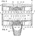
本発明は、以下の方法で作動する。可撓性バネ44は、弛緩した、圧力のかかっていない状態(図3)では、凹形であり、即ち、プランジャ14(図3において図示せず)の方向の後方へ(上方へ)湾曲される。可撓性バネ44が、この弛緩した状態にあるときは、弁部材の円板形状部分52は、ノズル42の傾斜縁部またはリム43に着座して、インクが流れることはできない。
The present invention operates in the following manner. The
プランジャ14に圧力が及ぼされると(図4の矢印によって示す)、プランジャ14は、前方の(下方の)カートリッジ内へ押し入れられ、それによって、インクが、バネ44と、弁部材の円板形状部分52とに圧力を及ぼすようになる。インクの圧力が、バネ44の付勢力を超えると、弁部材50は、図4に示す通り、前方へ移動して、可撓性バネ44を下向きに引っ張り、ノズルのリム43と弁の円板形状部分52との間に環状開口部60をつくりだし、そこを通ってインクが流れることができる。
When pressure is applied to the plunger 14 (indicated by the arrow in FIG. 4), the plunger 14 is pushed into the front (lower) cartridge, thereby causing ink to flow through the
インク圧力の力が、バネの付勢力よりも低下すると、可撓性バネ44は、元の凹形の位置に戻って、弁の円板形状部分52を、ノズルのリム43に再度着座させ、自動的に弁を閉鎖する。
When the ink pressure force drops below the spring biasing force, the
インクの流れを誘導する助けとなるように、任意選択のノズル延長部62(図2および4)を、分配用取付部品16から延びる、実質的に円筒状のノズル42に、スナップ式取付手段、または他の取付手段によって取り付けることができる。任意選択の着脱可能な蓋部64(図1および3)を使用して、カートリッジ10を使用していないときに、弁部材50を遮蔽することができる。
An optional nozzle extension 62 (FIGS. 2 and 4) is attached to the substantially
カートリッジは、任意選択のノズル延長部62を使用せずに(しかし、好ましくは任意選択の蓋部64を取り付けて)、その分配端部を下向きに伏せて、平板な表面に設置することができる。カートリッジを、このようにして、使用スタンバイとなるまで、積み上げておくことができる。
The cartridge can be placed on a flat surface without the optional nozzle extension 62 (but preferably with the
したがって、本発明は、インクからの圧力を受けると開き、たとえ粘度の低いインクを用いて使用した場合でも、弁への圧力が所定レベルよりも低下すると自動的に且つ完全に閉鎖する、自動閉鎖弁を有するインクカートリッジを提供する。 Therefore, the present invention opens automatically upon receiving pressure from the ink and automatically closes automatically and completely when the pressure on the valve drops below a predetermined level, even when used with low viscosity ink. An ink cartridge having a valve is provided.
プランジャ端部が、押し下げられて、インクを、ノズル42と弁部材50の間の環状開口部60を経由して押し出すと、カートリッジは、自動的にインクを分配する。プランジャへの圧力が、所定のレベルまで低下すると、弁は、自動的に、かつ完全に閉鎖する。本発明は、自動式インクレベルセンサを有する給紙式石版印刷機で使用する、インク分配器として特に適している。
As the plunger end is depressed to push ink out through the
本発明の他の変更形態、および代替的実施形態もここに企図するが、それらは、前述の教示および添付の請求項によって規定される通りの、本発明の趣旨および範囲から逸脱するものではない。請求項は、それらの範囲に該当する全てのそのような変形形態を網羅するものである。 Other variations and alternative embodiments of the invention are also contemplated herein, but they do not depart from the spirit and scope of the invention as defined by the foregoing teachings and the appended claims. . The claims are intended to cover all such variations that fall within those scope.
Claims (9)
該インクカートリッジ(10)に施された前記改良は、
前記オリフィスの周囲から延び、リム(43)を有し、且つ空間を画定するノズル(42)と、
前記ノズル(42)によって画定された空間内に取り付けられ、インクの流れを供給する開口部を有する可撓性バネ手段(44)と、
前記可撓性バネ手段(44)の下流に位置し、該可撓性バネ手段(44)によって支持される実質的に剛性の弁部材(50)であって、該可撓性バネ手段(44)の付勢力によって前記ノズルのリム(43)に押し当てられる閉鎖位置と、インクにより該バネ手段(44)および該弁部材(50)に対してかけられる圧力が該バネ手段(44)の付勢力を超えるとき、該弁部材(50)が該バネ手段(44)を下向きに引っ張り、環状開口部(60)をつくりだす開放位置との間を移動自在である前記弁部材(50)と、を含む、
ことを特徴とするインクカートリッジ(10)。An ink cartridge (10) having a predetermined improvement of the type used in a lithographic printing press, comprising a hollow cylindrical body (12) for holding provision of extrudable ink, the cylindrical shape The body (12) has a dispensing end and a plunger end closed by a plunger (14), the plunger (14) being adapted to function as a piston in the tubular body (12). When the plunger (14) is pushed toward the dispensing end, the contents of the ink cartridge (10) are pushed out and the dispensing end is closed by the dispensing fitting (16) attached thereto. The dispensing fitting (16) is disposed within the shielding portion (32), a flat shielding portion (32), a side wall (34) formed around the shielding portion (32), and the shielding portion (32). Orifi (38) and provided with, in the ink cartridge (10),
The improvements made to the ink cartridge (10) are:
A nozzle (42) extending from the periphery of the orifice, having a rim (43) and defining a space;
Flexible spring means (44) mounted in a space defined by the nozzle (42) and having an opening for supplying ink flow;
A substantially rigid valve member (50) positioned downstream of and supported by the flexible spring means (44), the flexible spring means (44). ), And the pressure applied to the spring means (44) and the valve member (50) by the ink is applied to the spring means (44). The valve member (50) being movable between an open position where the valve member (50) pulls the spring means (44) downward and creates an annular opening (60) when the force is exceeded; Including,
An ink cartridge (10) characterized by the above.
Applications Claiming Priority (2)
| Application Number | Priority Date | Filing Date | Title |
|---|---|---|---|
| US09/928,217 US6477956B1 (en) | 2001-08-10 | 2001-08-10 | Ink cartridge with self-closing valve |
| PCT/US2002/022864 WO2003013873A2 (en) | 2001-08-10 | 2002-07-19 | Ink cartridge with self-closing valve |
Publications (2)
| Publication Number | Publication Date |
|---|---|
| JP2004537444A JP2004537444A (en) | 2004-12-16 |
| JP4067488B2 true JP4067488B2 (en) | 2008-03-26 |
Family
ID=25455902
Family Applications (1)
| Application Number | Title | Priority Date | Filing Date |
|---|---|---|---|
| JP2003518843A Expired - Lifetime JP4067488B2 (en) | 2001-08-10 | 2002-07-19 | ink cartridge |
Country Status (12)
| Country | Link |
|---|---|
| US (1) | US6477956B1 (en) |
| EP (1) | EP1414651B1 (en) |
| JP (1) | JP4067488B2 (en) |
| CN (1) | CN100335293C (en) |
| AT (1) | ATE407013T1 (en) |
| AU (1) | AU2002355390B2 (en) |
| CA (1) | CA2452837C (en) |
| DE (1) | DE60228728D1 (en) |
| ES (1) | ES2314079T3 (en) |
| MX (1) | MXPA04001281A (en) |
| TW (1) | TW550180B (en) |
| WO (1) | WO2003013873A2 (en) |
Families Citing this family (10)
| Publication number | Priority date | Publication date | Assignee | Title |
|---|---|---|---|---|
| US6474511B1 (en) * | 2001-08-31 | 2002-11-05 | Sonoco Development, Inc. | Safety cap for fluid dispensing cartridges |
| US20040137327A1 (en) * | 2003-01-13 | 2004-07-15 | Gross Karl J. | Synthesis of carbon/silicon composites |
| US7635180B2 (en) * | 2005-09-29 | 2009-12-22 | Brother Kogyo Kabushiki Kaisha | Ink cartridge |
| EP1864917B1 (en) * | 2006-06-06 | 2008-08-13 | Nestec S.A. | Capsule with reduced dripping |
| JP5255802B2 (en) * | 2007-09-14 | 2013-08-07 | アイマー・プランニング株式会社 | Printer |
| JP2009202434A (en) * | 2008-02-28 | 2009-09-10 | Seiko Epson Corp | Fluid jetting apparatus |
| KR20140062523A (en) * | 2012-11-12 | 2014-05-26 | 주식회사 두원정밀 | Cartridge for solder cream supply unit of the screen printer |
| CN108382072A (en) * | 2017-02-03 | 2018-08-10 | 正中科技股份有限公司 | For halftone or the black box structure of typographical printing equipment |
| CN112009111A (en) * | 2020-09-14 | 2020-12-01 | 桑华超 | Energy-saving and environment-friendly ink box production equipment |
| CN113085360B (en) * | 2021-04-27 | 2022-11-15 | 江苏凤凰通达印刷有限公司 | Environment-friendly printing process and equipment for paper products |
Family Cites Families (14)
| Publication number | Priority date | Publication date | Assignee | Title |
|---|---|---|---|---|
| US4513784A (en) | 1984-04-18 | 1985-04-30 | General Motors Corporation | Check valve assembly |
| US4677447A (en) | 1986-03-20 | 1987-06-30 | Hewlett-Packard Company | Ink jet printhead having a preloaded check valve |
| US5606988A (en) | 1994-02-04 | 1997-03-04 | Hewlett -Packard Company | Connector assembly for ink cartridge |
| JPH08174860A (en) | 1994-10-26 | 1996-07-09 | Seiko Epson Corp | Ink cartridge for ink jet printer |
| JP3417434B2 (en) | 1995-01-05 | 2003-06-16 | セイコーエプソン株式会社 | Ink cartridge for inkjet printer |
| US5721577A (en) | 1995-05-04 | 1998-02-24 | Calcomp Inc. | Large capacity ink cartridge |
| US6172694B1 (en) | 1997-02-13 | 2001-01-09 | Marconi Data Systems Inc. | Check valve for ink jet printing |
| JP4141523B2 (en) * | 1997-03-19 | 2008-08-27 | セイコーエプソン株式会社 | Ink supply flow path valve device |
| JPH11145147A (en) * | 1997-11-11 | 1999-05-28 | Nec Corp | Semiconductor device and its manufacture |
| DE19757161A1 (en) * | 1997-12-20 | 1999-06-24 | Heidelberger Druckmasch Ag | Method and device for feeding printing ink in the inking unit of printing machines |
| DE19936482A1 (en) * | 1998-12-05 | 2000-06-21 | Frank Ritter | Cartridge seal with valve function for plastic printer cartridge, with valve sleeve axially moved when pressure is applied to cartridge contents to free opening between neck and central body |
| DE60010996T2 (en) * | 1999-03-29 | 2005-06-09 | Seiko Epson Corp. | Method and device for filling ink cartridges with ink |
| US6145973A (en) | 1999-09-14 | 2000-11-14 | Wisertek International Corp. | Ink-jet cartridge |
| US6192797B1 (en) * | 1999-12-23 | 2001-02-27 | Sonoco Development, Inc. | Ink cartridge for automated dispensing systems |
-
2001
- 2001-08-10 US US09/928,217 patent/US6477956B1/en not_active Expired - Lifetime
-
2002
- 2002-07-19 JP JP2003518843A patent/JP4067488B2/en not_active Expired - Lifetime
- 2002-07-19 AT AT02752439T patent/ATE407013T1/en not_active IP Right Cessation
- 2002-07-19 CA CA002452837A patent/CA2452837C/en not_active Expired - Lifetime
- 2002-07-19 CN CNB02812572XA patent/CN100335293C/en not_active Expired - Fee Related
- 2002-07-19 WO PCT/US2002/022864 patent/WO2003013873A2/en active IP Right Grant
- 2002-07-19 ES ES02752439T patent/ES2314079T3/en not_active Expired - Lifetime
- 2002-07-19 EP EP02752439A patent/EP1414651B1/en not_active Expired - Lifetime
- 2002-07-19 DE DE60228728T patent/DE60228728D1/en not_active Expired - Lifetime
- 2002-07-19 AU AU2002355390A patent/AU2002355390B2/en not_active Ceased
- 2002-07-19 MX MXPA04001281A patent/MXPA04001281A/en active IP Right Grant
- 2002-08-05 TW TW091117551A patent/TW550180B/en not_active IP Right Cessation
Also Published As
| Publication number | Publication date |
|---|---|
| DE60228728D1 (en) | 2008-10-16 |
| ES2314079T3 (en) | 2009-03-16 |
| JP2004537444A (en) | 2004-12-16 |
| CA2452837C (en) | 2008-09-23 |
| EP1414651A4 (en) | 2005-12-21 |
| CA2452837A1 (en) | 2003-02-20 |
| TW550180B (en) | 2003-09-01 |
| EP1414651A2 (en) | 2004-05-06 |
| CN100335293C (en) | 2007-09-05 |
| CN1635956A (en) | 2005-07-06 |
| EP1414651B1 (en) | 2008-09-03 |
| MXPA04001281A (en) | 2004-06-03 |
| WO2003013873A2 (en) | 2003-02-20 |
| WO2003013873A3 (en) | 2003-04-24 |
| US6477956B1 (en) | 2002-11-12 |
| AU2002355390B2 (en) | 2005-10-27 |
| ATE407013T1 (en) | 2008-09-15 |
Similar Documents
| Publication | Publication Date | Title |
|---|---|---|
| JP4067488B2 (en) | ink cartridge | |
| US2754033A (en) | Ink dispenser | |
| JP2766235B2 (en) | Apparatus and method for adjusting the valve of an ink container | |
| US6192797B1 (en) | Ink cartridge for automated dispensing systems | |
| GB2188118A (en) | Solvent-recirculating cleaning apparatus | |
| US3973699A (en) | Liquid dispensing apparatus utilizing double acting piston | |
| US4870431A (en) | Ink jet priming system | |
| AU2002355390A1 (en) | Ink cartridge with self-closing valve | |
| JPH0655728A (en) | Portable, detachable, and intertable ink fountain box for printing press | |
| KR102445985B1 (en) | Solder paste supply assembly and solder paste supply method | |
| CN100584608C (en) | Printing machine | |
| AU2002250614B2 (en) | Ink cartridge plunger | |
| EP1324882B1 (en) | Ink cartridge valve system | |
| AU2001296543A1 (en) | Ink cartridge valve system | |
| JP2759792B2 (en) | Printing ink supply device and printing ink container | |
| EP1369245B1 (en) | Ink supply system and ink supply method for stencil printer and ink container | |
| JP4035746B2 (en) | Printing ink supply method | |
| JP3668056B2 (en) | Printing device and developing device | |
| US5189954A (en) | Ink supplying device for a printing press | |
| IE60603B1 (en) | Improvements in or relating to inking systems | |
| JP2020040269A (en) | Liquid discharge device | |
| KR20010064302A (en) | Ink cartridge for liquid electrophotographic printer | |
| JP2003305934A (en) | Ink feeding device for stencil printing apparatus and ink bottle used for it | |
| MXPA98007363A (en) | Deposit for you |
Legal Events
| Date | Code | Title | Description |
|---|---|---|---|
| A131 | Notification of reasons for refusal |
Free format text: JAPANESE INTERMEDIATE CODE: A131 Effective date: 20070508 |
|
| A521 | Request for written amendment filed |
Free format text: JAPANESE INTERMEDIATE CODE: A523 Effective date: 20070803 |
|
| TRDD | Decision of grant or rejection written | ||
| A01 | Written decision to grant a patent or to grant a registration (utility model) |
Free format text: JAPANESE INTERMEDIATE CODE: A01 Effective date: 20071218 |
|
| A61 | First payment of annual fees (during grant procedure) |
Free format text: JAPANESE INTERMEDIATE CODE: A61 Effective date: 20080108 |
|
| FPAY | Renewal fee payment (event date is renewal date of database) |
Free format text: PAYMENT UNTIL: 20110118 Year of fee payment: 3 |
|
| R150 | Certificate of patent or registration of utility model |
Free format text: JAPANESE INTERMEDIATE CODE: R150 Ref document number: 4067488 Country of ref document: JP Free format text: JAPANESE INTERMEDIATE CODE: R150 |
|
| FPAY | Renewal fee payment (event date is renewal date of database) |
Free format text: PAYMENT UNTIL: 20110118 Year of fee payment: 3 |
|
| FPAY | Renewal fee payment (event date is renewal date of database) |
Free format text: PAYMENT UNTIL: 20120118 Year of fee payment: 4 |
|
| R250 | Receipt of annual fees |
Free format text: JAPANESE INTERMEDIATE CODE: R250 |
|
| FPAY | Renewal fee payment (event date is renewal date of database) |
Free format text: PAYMENT UNTIL: 20130118 Year of fee payment: 5 |
|
| R250 | Receipt of annual fees |
Free format text: JAPANESE INTERMEDIATE CODE: R250 |
|
| FPAY | Renewal fee payment (event date is renewal date of database) |
Free format text: PAYMENT UNTIL: 20130118 Year of fee payment: 5 |
|
| R250 | Receipt of annual fees |
Free format text: JAPANESE INTERMEDIATE CODE: R250 |
|
| R250 | Receipt of annual fees |
Free format text: JAPANESE INTERMEDIATE CODE: R250 |
|
| R250 | Receipt of annual fees |
Free format text: JAPANESE INTERMEDIATE CODE: R250 |
|
| R250 | Receipt of annual fees |
Free format text: JAPANESE INTERMEDIATE CODE: R250 |
|
| R250 | Receipt of annual fees |
Free format text: JAPANESE INTERMEDIATE CODE: R250 |
|
| R250 | Receipt of annual fees |
Free format text: JAPANESE INTERMEDIATE CODE: R250 |
|
| R250 | Receipt of annual fees |
Free format text: JAPANESE INTERMEDIATE CODE: R250 |
|
| R250 | Receipt of annual fees |
Free format text: JAPANESE INTERMEDIATE CODE: R250 |
|
| R250 | Receipt of annual fees |
Free format text: JAPANESE INTERMEDIATE CODE: R250 |
|
| R250 | Receipt of annual fees |
Free format text: JAPANESE INTERMEDIATE CODE: R250 |
|
| EXPY | Cancellation because of completion of term |