JP4065922B2 - Binoculars holding device - Google Patents
Binoculars holding device Download PDFInfo
- Publication number
- JP4065922B2 JP4065922B2 JP17296898A JP17296898A JP4065922B2 JP 4065922 B2 JP4065922 B2 JP 4065922B2 JP 17296898 A JP17296898 A JP 17296898A JP 17296898 A JP17296898 A JP 17296898A JP 4065922 B2 JP4065922 B2 JP 4065922B2
- Authority
- JP
- Japan
- Prior art keywords
- binoculars
- holding device
- bottom support
- support plate
- mounting plate
- Prior art date
- Legal status (The legal status is an assumption and is not a legal conclusion. Google has not performed a legal analysis and makes no representation as to the accuracy of the status listed.)
- Expired - Lifetime
Links
Images


Landscapes
- Telescopes (AREA)
Description
【0001】
【発明の属する技術分野】
本発明は、架台に支持される双眼鏡の保持装置に関するものである。
【0002】
【従来の技術】
従来の架台に支持される双眼鏡の保持装置は、図6、図7に示す如く構成されていた。
以下、図面を参照して従来の双眼鏡の保持装置を説明する。
図7は、従来の双眼鏡の保持装置及び保持される双眼鏡の斜視図である。
【0003】
図7において、双眼鏡21の中心軸24の対物側先端面には、保持装置に支持させるための雌ネジ24aが螺刻されており、先端外周には、ネジ24bが螺刻されている。保持装置を使用しない通常の使用状態では、キャップ23がネジ23に螺合して固定され、雌ネジ24aを覆っている。保持装置の基体部22は、L字形状部材であり、架台26に固定される当接面には、架台26の有する取り付けネジが嵌合する、雌ネジが長手方向に2カ所螺刻されている。そして、当接面に直交する直立部には、双眼鏡21の中心軸24に螺刻された雌ネジ24aに螺合する支持ネジ25aが螺刻された締め付けノブ25が設けられている。
【0004】
上記の如き構成にあっては、架台26を使用して観察する場合、まず、双眼鏡21からキャップ23を取り外すことによって雌ネジ24aを露出させる。その後、保持装置の締め付けノブ25を回転させて、支持ネジ25aを雌ネジ24aに螺合させることによって、基体部22と双眼鏡21とを一体と成す。そして、基体部22を、架台26の有する取り付けネジと、雌ネジとの螺合によって双眼鏡21が、架台26に固定される。
【0005】
図8は、従来の双眼鏡の保持装置及び保持される双眼鏡の斜視図である。
図8において、保持装置に保持される双眼鏡21は中心軸34を有している。保持装置の基体部32の端部には、支持受け部36が設けられている。支持受け部36は、中心軸34を挿入する為の挿入部36cが形成されており、その底部には、中心軸34を挟持するための円弧状の溝36bが形成され、外周部には、雄ネジ36aが設けられている。また、支持押さえ部35は、挿入部36cに挿入して中心軸34を確実に支持するための嵌合面35bと、円弧状の溝35aが形成されている。そして、嵌合面35bとは一体で回動可能なノブ35cを備えている。また、ノブ35cは内周部に雌ネジが螺刻されている。
【0006】
上記の如き構成にあっては、双眼鏡31の中心軸34を、挿入部36cに挿入して円弧状の溝36bに当接させる。その後、支持押さえ部35を挿入して円筒状の溝35aと、円筒状の溝36bとで中心軸34を挟持すると共に、ノブ35cを回転させて、雄ネジ部36aに支持押さえ部35を螺合させ固定させる。これによって、双眼鏡31が保持装置に固定される。
【0007】
【発明が解決しようとする課題】
このような従来の構成においては、双眼鏡の中心軸周辺に保持装置を配置させるためのスペースを必要としていた。そのために、外観上で大事な正面のデザインに制約を受けるという問題点があった。
また、ダハタイプの双眼鏡にあっては、中心軸周辺に保持装置を取りつけるスペースが無いので、現存タイプの保持装置を使用することができず、また、ダハタイプ用の保持装置は作られていなかった。
【0008】
本発明は、このような従来の技術に鑑みてなされたものであり、その目的とするところは、一般的に使用される双眼鏡においては、如何なるタイプのものであっても確実に保持できる双眼鏡の保持装置を提供することにある。
【0009】
【課題を解決するための手段】
上記目的を達成するために、本願は下記を提案する。
【0010】
双眼鏡を保持し所望の高さ位置に置いて架台によって支持される双眼鏡の保持装置において、底部支持板と、前記底部支持板上に設けられ、その左右両端に固定された2つの直立柱と、前記直立柱どうしを連結し、保持される双眼鏡の左右の対物レンズ鏡筒付近を共に挟持可能な押さえ部材と、前記底部支持板の下部に回転可能に設けられた駆動ノブと、前記底部支持板の上方に配置され双眼鏡が載置される載置板と、前記載置板に設けられ前記2つの直立柱の各々を貫通させる2つの貫通孔と、前記載置板の下部の略中央部には、架台に固定される基体部を有し、さらに前記載置板の下部には、前記基体部に対し、載置される双眼鏡の対物レンズ側に配置され前記駆動ノブと螺合する駆動軸とを有し、 前記駆動ノブを一方の方向へ回転させると、前記底部支持板が上方に移動することで前記2つの直立柱も上方に移動し、前記駆動ノブを他方の方向へ回転させると、前記底部支持板が下方に移動することで前記2つの直立柱も下方に移動し、双眼鏡を前記載置板と前記押さえ部材との間への開放と挟持を可能にすることを特徴とする双眼鏡の保持装置(請求項1)を提供する。
【0011】
第二に、請求項1に記載の双眼鏡の保持装置は、前記載置板において双眼鏡の接眼部が載置される領域は、双眼鏡の対物部が載置される領域よりも上方に高くなっている段差を有することを特徴とする(請求項2)を提供する。
【0012】
【発明の実施の形態】
以下、本発明の実施の形態を、図面を参照して説明する。
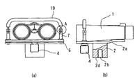
図1は、本発明の保持装置の実施形態を示す図であり、双眼鏡を載置した状態を説明する図である。(a)は正面図、(b)は一部断面の側面図である。
図2は、本発明の保持装置の実施形態を示す図であり、双眼鏡を載置した後に固定した状態を説明する図である。(a)は正面図、(b)は一部断面の側面図である。
【0013】
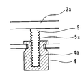
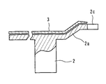
図3は、図1(a)のA部を拡大した図であり、図4は、図2(a)のB部を拡大した図であり、図5は、図1(a)C部を拡大した図である。
図1、図2、図3,図4、図5及び図6において、双眼鏡1は、図1に示す如く基体部2の架台への取り付け面2dの反対の面に、一体に設けられた載置板2aに載置されている。なお、本実施の形態にあっては、基体部2と載置板2aは樹脂にて一体成形されている。基体部2は、取り付け面2dに不図示の架台の固定ネジに螺合する雌ネジ2bが螺刻されている。載置板2aは、樹脂で成形され可撓性を有しており、図6に示す如く、全体が平面でなく、その後部(接眼部の載置部)が一段高くなっており、この部分の後端部に鼻当たりを防ぐ為の切り欠き部2cが形成されている。そして、前部平坦部には、載置される双眼鏡の光軸と直交する方向に、左右に振り分けて2つの貫通孔2eが設けられている。また、この左右振り分けの中央部の載置板2aの板裏部には、下方に延在する駆動軸5が植設されており、その外径には、駆動雄ネジが螺刻されている。さらに、載置板2aの上面には、双眼鏡1をソフトに載置させるための緩衝保持板3が固設されている。
【0014】
載置板2aの2つの貫通孔2eには、移動部材の側部を構成する直立柱7がそれぞれに貫通している。そして、直立柱7のそれぞれの下方端部は、底部支持板6によって、略コ字形を成す如く一体に固設されている。底部支持板6は、略中央部に駆動ノブ4を軸方向の移動を阻止し、回動自在に保持している。この駆動ノブ4は、内径部に駆動雌ネジ4aが螺刻されており、駆動軸5の駆動雄ネジ5aに螺合している。
【0015】
直立柱7のそれぞれの上方端部には、双眼鏡1の光軸方向と同方向に切り欠かれた溝8aが形成されている。この溝8aには、押さえ部材9の先端部が嵌合し、ピン8によって支持され、溝8aに沿って揺動可能に構成されている。そして、押さえ部材9は、緩衝部材10によって被覆されている。
このように構成された双眼鏡の保持装置は、以下の如くして使用される。
【0016】
まず、双眼鏡1を載置板2a上の緩衝保持板3に載置する。このとき、後部段差部に接眼部、対物部を前部の押さえ部材9の作用可能位置になるようにする。この状態は、図1(a)、(b)に示す通りである。
双眼鏡1を所望の位置に載置完了すると、駆動ノブ4を回転させる。この回転によって、駆動雌ネジ4aに螺合する駆動軸5の駆動雄ネジ5aの作用によって、底部支持板6を載置板2aから離間する方向、即ち、下方に移動させる。この移動を受けて、底部支持板6と一体の直立柱7は、貫通孔2e内を下方に移動する。従って、押さえ部材9も下方に移動して双眼鏡1に緩衝部材10が当接して双眼鏡1が保持固定される。この状態は図2(a)、(b)に示す通りである。
【0017】
この保持固定は、緩衝保持板3と緩衝部材10とによって、ソフトに保持されるが、本実施形態では、さらに、載置板2aに可撓性を持たせてあるので、より確実な保持固定を可能としている。また、緩衝部材10が双眼鏡1に当接した後の駆動ノブ4の操作が若干強すぎても、双眼鏡1の品質に影響を与えることもない。
【0018】
双眼鏡1を保持装置から外す場合には、駆動ノブ4を取り付け時に対して逆回転させて、緩衝部材10の当接を解除すればよい。
保持装置から双眼鏡1を取り外した後に、押さえ部材9を溝8aに沿って揺動させて倒し、保持装置をコンパクトにする。
【0019】
【発明の効果】
以上説明したように、本発明によれば、双眼鏡の中心軸周辺に保持装置を配置させるための構成を必要としないので、外観上で大事な正面のデザインに対する自由度が増すという効果を奏する。
また、中心軸周辺に保持装置を取りつけるスペースが無いダハタイプの双眼鏡であっても、架台に取り付けて使用することができるという効果も奏する。
【図面の簡単な説明】
【図1】本発明の保持装置の実施形態を示す図であり、双眼鏡を載置した状態を説明する図である。(a)は正面図、(b)は一部断面の側面図である。
【図2】本発明の保持装置の実施形態を示す図であり、双眼鏡を載置した後に固定した状態を説明する図である。(a)は正面図、(b)は一部断面の側面図である。
【図3】図1(a)のA部を拡大した図である。
【図4】図2(a)のB部を拡大した図である。
【図5】図1(a)C部を拡大した図である。
【図6】本発明の基体部、載置板、及び緩衝保持板を説明する一部断面の側面図である。
【図7】従来の双眼鏡の保持装置及び保持される双眼鏡の斜視図である。
【図8】従来の双眼鏡の保持装置及び保持される双眼鏡の斜視図である。
【符号の説明】
1 双眼鏡
2 基体部
2a 載置板
2b 雌ネジ
2c 切り欠き部
2d 取り付け面
2e 貫通孔
3 緩衝保持板
4 駆動ノブ
4a 駆動雌ネジ
5 駆動軸
5a 駆動雄ネジ
6 底部支持板
7 直立柱
8 ピン
9 押さえ部材
10 緩衝部材[0001]
BACKGROUND OF THE INVENTION
The present invention relates to a holding device for binoculars supported by a gantry.
[0002]
[Prior art]
Conventional binocular holding devices supported by a gantry are configured as shown in FIGS.
A conventional binocular holding device will be described below with reference to the drawings.
FIG. 7 is a perspective view of a conventional binocular holding device and binoculars to be held.
[0003]
In FIG. 7, a female screw 24a to be supported by the holding device is threaded on the objective-side distal surface of the central axis 24 of the binoculars 21, and a screw 24b is threaded on the outer periphery of the distal end. In a normal use state in which the holding device is not used, the cap 23 is screwed and fixed to the screw 23 and covers the female screw 24a. The base portion 22 of the holding device is an L-shaped member, and an abutment surface fixed to the
[0004]
In the above configuration, when observing using the
[0005]
FIG. 8 is a perspective view of a conventional binocular holding device and the binoculars to be held.
In FIG. 8, the binoculars 21 held by the holding device has a
[0006]
In the configuration as described above, the
[0007]
[Problems to be solved by the invention]
In such a conventional configuration, a space for arranging the holding device around the central axis of the binoculars is required. For this reason, there is a problem that the front design, which is important in appearance, is restricted.
Further, in the case of Dach type binoculars, since there is no space for attaching a holding device around the central axis, the existing type holding device cannot be used, and a Dach type holding device has not been made.
[0008]
The present invention has been made in view of such conventional techniques, and the object of the present invention is to use binoculars that can be reliably held in any type of binoculars that are generally used. It is to provide a holding device.
[0009]
[Means for Solving the Problems]
In order to achieve the above object, the present application proposes the following.
[0010]
In a binocular holding device that holds binoculars and is supported by a gantry at a desired height position, a bottom support plate, and two upright columns provided on the bottom support plate and fixed to the left and right ends thereof, A pressing member that connects the upright columns and can hold both the left and right objective lens barrels of binoculars held together, a drive knob that is rotatably provided at a lower portion of the bottom support plate, and the bottom support plate A mounting plate disposed above the binoculars, two through holes provided in the mounting plate and penetrating each of the two upright columns, and a substantially central portion below the mounting plate. Has a base part fixed to the gantry, and further, on the lower part of the mounting plate described above, a drive shaft that is arranged on the objective lens side of the binoculars placed on the base part and screwed with the drive knob And rotate the drive knob in one direction. Then, when the bottom support plate is moved upward, the two upright columns are also moved upward. When the drive knob is rotated in the other direction, the bottom support plate is moved downward so that the 2 There is provided a binocular holding device (Claim 1) characterized in that two upright columns also move downward to allow the binoculars to be opened and clamped between the mounting plate and the pressing member.
[0011]
Secondly, in the binocular holding device according to claim 1, the region where the eyepiece part of the binoculars is placed on the mounting plate is higher than the region where the objective part of the binoculars is placed. The present invention provides (claim 2) characterized by having a step difference.
[0012]
DETAILED DESCRIPTION OF THE INVENTION
Hereinafter, embodiments of the present invention will be described with reference to the drawings.
FIG. 1 is a diagram illustrating an embodiment of a holding device of the present invention, and is a diagram illustrating a state where binoculars are placed. (A) is a front view, (b) is a side view of a partial cross section.
FIG. 2 is a diagram illustrating an embodiment of the holding device of the present invention, and is a diagram illustrating a state in which the binoculars are fixed after being placed. (A) is a front view, (b) is a side view of a partial cross section.
[0013]
3 is an enlarged view of part A in FIG. 1 (a), FIG. 4 is an enlarged view of part B in FIG. 2 (a), and FIG. 5 is a view of part C in FIG. 1 (a). FIG.
1, 2, 3, 4, 5, and 6, the binoculars 1 are mounted integrally on the surface opposite to the
[0014]
[0015]
A
The binocular holding device configured as described above is used as follows.
[0016]
First, the binoculars 1 are placed on the
When the binoculars 1 are completely placed at a desired position, the
[0017]
This holding and fixing is softly held by the
[0018]
When the binoculars 1 are removed from the holding device, the
After removing the binoculars 1 from the holding device, the holding
[0019]
【The invention's effect】
As described above, according to the present invention, since a configuration for arranging the holding device around the central axis of the binoculars is not required, there is an effect that the degree of freedom with respect to the front design that is important in appearance is increased.
Moreover, even if it is Dach type binoculars which do not have the space which attaches a holding | maintenance apparatus to the periphery of a central axis, there also exists an effect that it can attach and use for a mount frame.
[Brief description of the drawings]
FIG. 1 is a diagram illustrating an embodiment of a holding device according to the present invention, and is a diagram illustrating a state in which binoculars are placed. (A) is a front view, (b) is a side view of a partial cross section.
FIG. 2 is a diagram illustrating an embodiment of a holding device of the present invention, and is a diagram illustrating a state in which binoculars are fixed after being placed. (A) is a front view, (b) is a side view of a partial cross section.
FIG. 3 is an enlarged view of a portion A in FIG.
FIG. 4 is an enlarged view of a portion B in FIG.
FIG. 5 is an enlarged view of part C in FIG.
FIG. 6 is a partial cross-sectional side view illustrating a base portion, a mounting plate, and a buffer holding plate according to the present invention.
FIG. 7 is a perspective view of a conventional binocular holding device and held binoculars.
FIG. 8 is a perspective view of a conventional binocular holding device and held binoculars.
[Explanation of symbols]
DESCRIPTION OF SYMBOLS 1
Claims (2)
底部支持板と、
前記底部支持板上に設けられ、その左右両端に固定された2つの直立柱と、
前記直立柱どうしを連結し、保持される双眼鏡の左右の対物レンズ鏡筒付近を共に挟持可能な押さえ部材と、
前記底部支持板の下部に回転可能に設けられた駆動ノブと、
前記底部支持板の上方に配置され双眼鏡が載置される載置板と、
前記載置板に設けられ前記2つの直立柱の各々を貫通させる2つの貫通孔と、
前記載置板の下部の略中央部には、架台に固定される基体部を有し、
さらに前記載置板の下部には、前記基体部に対し、載置される双眼鏡の対物レンズ側に配置され前記駆動ノブと螺合する駆動軸とを有し、
前記駆動ノブを一方の方向へ回転させると、前記底部支持板が上方に移動することで前記2つの直立柱も上方に移動し、前記駆動ノブを他方の方向へ回転させると、前記底部支持板が下方に移動することで前記2つの直立柱も下方に移動し、双眼鏡を前記載置板と前記押さえ部材との間への開放と挟持を可能にすることを特徴とする双眼鏡の保持装置。In a binocular holding device that holds binoculars and is supported by a gantry at a desired height position,
A bottom support plate;
Two upright columns provided on the bottom support plate and fixed to the left and right ends thereof;
A holding member that connects the upright columns and can hold both the left and right objective lens barrels of binoculars held together,
A drive knob rotatably provided at the bottom of the bottom support plate;
A mounting plate disposed above the bottom support plate and on which binoculars are mounted;
Two through holes provided in the mounting plate and penetrating each of the two upright columns;
In the substantially central portion of the lower portion of the mounting plate, there is a base portion fixed to the gantry,
Furthermore, the lower part of the mounting plate has a drive shaft that is disposed on the objective lens side of the binoculars to be placed and is screwed with the drive knob, with respect to the base body part,
When the drive knob is rotated in one direction, the bottom support plate is moved upward, so that the two upright columns are also moved upward. When the drive knob is rotated in the other direction, the bottom support plate is moved. The binoculars holding device is characterized in that the two upright columns also move downward by moving downward and the binoculars can be opened and clamped between the mounting plate and the pressing member.
Priority Applications (1)
| Application Number | Priority Date | Filing Date | Title |
|---|---|---|---|
| JP17296898A JP4065922B2 (en) | 1998-06-19 | 1998-06-19 | Binoculars holding device |
Applications Claiming Priority (1)
| Application Number | Priority Date | Filing Date | Title |
|---|---|---|---|
| JP17296898A JP4065922B2 (en) | 1998-06-19 | 1998-06-19 | Binoculars holding device |
Publications (3)
| Publication Number | Publication Date |
|---|---|
| JP2000010020A JP2000010020A (en) | 2000-01-14 |
| JP2000010020A5 JP2000010020A5 (en) | 2005-10-06 |
| JP4065922B2 true JP4065922B2 (en) | 2008-03-26 |
Family
ID=15951705
Family Applications (1)
| Application Number | Title | Priority Date | Filing Date |
|---|---|---|---|
| JP17296898A Expired - Lifetime JP4065922B2 (en) | 1998-06-19 | 1998-06-19 | Binoculars holding device |
Country Status (1)
| Country | Link |
|---|---|
| JP (1) | JP4065922B2 (en) |
Cited By (2)
| Publication number | Priority date | Publication date | Assignee | Title |
|---|---|---|---|---|
| JP2011064896A (en) * | 2009-09-16 | 2011-03-31 | Nikon Vision Co Ltd | Binocular holding device |
| WO2012124984A2 (en) * | 2011-03-16 | 2012-09-20 | Samsung Electronics Co., Ltd. | Support device for three-dimensional glasses |
-
1998
- 1998-06-19 JP JP17296898A patent/JP4065922B2/en not_active Expired - Lifetime
Cited By (3)
| Publication number | Priority date | Publication date | Assignee | Title |
|---|---|---|---|---|
| JP2011064896A (en) * | 2009-09-16 | 2011-03-31 | Nikon Vision Co Ltd | Binocular holding device |
| WO2012124984A2 (en) * | 2011-03-16 | 2012-09-20 | Samsung Electronics Co., Ltd. | Support device for three-dimensional glasses |
| WO2012124984A3 (en) * | 2011-03-16 | 2012-12-27 | Samsung Electronics Co., Ltd. | Support device for three-dimensional glasses |
Also Published As
| Publication number | Publication date |
|---|---|
| JP2000010020A (en) | 2000-01-14 |
Similar Documents
| Publication | Publication Date | Title |
|---|---|---|
| JPH08108358A (en) | Optical fiber end surface polishing device having ferrule fixing means | |
| JP4065922B2 (en) | Binoculars holding device | |
| JPH09313303A (en) | Play prevention mechanism for drum chair | |
| EP1048969A1 (en) | Apparatus for installing eyeglass lenses | |
| US4593227A (en) | Cathode ray tube mounting means | |
| US5794913A (en) | Foot assembly for computer mainframes | |
| JP2001278167A (en) | Braking device for bicycle, and brake arm for braking device | |
| CN212322152U (en) | Intelligent tablet computer terminal of 5G medical care and emergency call system | |
| JP2505002Y2 (en) | Optical communication device | |
| JP7485363B2 (en) | Stay for mounting vehicle-mounted device and vehicle-mounted device | |
| JP3335135B2 (en) | Handrail mounting | |
| JPS62163474A (en) | Fitting mechanism for solid-state image pickup element | |
| JPH05341718A (en) | Electronic equipment and device | |
| KR0136576Y1 (en) | Fixing device for wheel alignment sensor | |
| JP4093441B2 (en) | Tension member fixing bracket | |
| US4092939A (en) | Tension disc assembly | |
| JPH0480189B2 (en) | ||
| JP2600903B2 (en) | Shaft fixing mechanism | |
| JP3359085B2 (en) | Worm gear loosening prevention device for shutter curtain speed adjustment | |
| JPH03220585A (en) | Display unit for display device | |
| JPH033990Y2 (en) | ||
| JPH036221Y2 (en) | ||
| US20210262516A1 (en) | Support frame using ball members | |
| JP2000010020A5 (en) | ||
| JPH0843772A (en) | Mounting structure for frame element of rimless spectacle |
Legal Events
| Date | Code | Title | Description |
|---|---|---|---|
| A521 | Written amendment |
Free format text: JAPANESE INTERMEDIATE CODE: A523 Effective date: 20050527 |
|
| A621 | Written request for application examination |
Free format text: JAPANESE INTERMEDIATE CODE: A621 Effective date: 20050527 |
|
| A977 | Report on retrieval |
Free format text: JAPANESE INTERMEDIATE CODE: A971007 Effective date: 20070418 |
|
| A131 | Notification of reasons for refusal |
Free format text: JAPANESE INTERMEDIATE CODE: A131 Effective date: 20070424 |
|
| A521 | Written amendment |
Free format text: JAPANESE INTERMEDIATE CODE: A523 Effective date: 20070625 |
|
| A131 | Notification of reasons for refusal |
Free format text: JAPANESE INTERMEDIATE CODE: A131 Effective date: 20070807 |
|
| A521 | Written amendment |
Free format text: JAPANESE INTERMEDIATE CODE: A523 Effective date: 20071004 |
|
| TRDD | Decision of grant or rejection written | ||
| A01 | Written decision to grant a patent or to grant a registration (utility model) |
Free format text: JAPANESE INTERMEDIATE CODE: A01 Effective date: 20071127 |
|
| A61 | First payment of annual fees (during grant procedure) |
Free format text: JAPANESE INTERMEDIATE CODE: A61 Effective date: 20071210 |
|
| FPAY | Renewal fee payment (event date is renewal date of database) |
Free format text: PAYMENT UNTIL: 20110118 Year of fee payment: 3 |
|
| R150 | Certificate of patent or registration of utility model |
Free format text: JAPANESE INTERMEDIATE CODE: R150 |
|
| FPAY | Renewal fee payment (event date is renewal date of database) |
Free format text: PAYMENT UNTIL: 20110118 Year of fee payment: 3 |
|
| FPAY | Renewal fee payment (event date is renewal date of database) |
Free format text: PAYMENT UNTIL: 20140118 Year of fee payment: 6 |
|
| FPAY | Renewal fee payment (event date is renewal date of database) |
Free format text: PAYMENT UNTIL: 20140118 Year of fee payment: 6 |
|
| S531 | Written request for registration of change of domicile |
Free format text: JAPANESE INTERMEDIATE CODE: R313531 |
|
| FPAY | Renewal fee payment (event date is renewal date of database) |
Free format text: PAYMENT UNTIL: 20140118 Year of fee payment: 6 |
|
| R350 | Written notification of registration of transfer |
Free format text: JAPANESE INTERMEDIATE CODE: R350 |
|
| R250 | Receipt of annual fees |
Free format text: JAPANESE INTERMEDIATE CODE: R250 |
|
| R250 | Receipt of annual fees |
Free format text: JAPANESE INTERMEDIATE CODE: R250 |
|
| R250 | Receipt of annual fees |
Free format text: JAPANESE INTERMEDIATE CODE: R250 |
|
| R250 | Receipt of annual fees |
Free format text: JAPANESE INTERMEDIATE CODE: R250 |
|
| R250 | Receipt of annual fees |
Free format text: JAPANESE INTERMEDIATE CODE: R250 |
|
| EXPY | Cancellation because of completion of term |