JP4065435B2 - Heat exchange plate, board package, and plate heat exchanger - Google Patents
Heat exchange plate, board package, and plate heat exchanger Download PDFInfo
- Publication number
- JP4065435B2 JP4065435B2 JP2003568328A JP2003568328A JP4065435B2 JP 4065435 B2 JP4065435 B2 JP 4065435B2 JP 2003568328 A JP2003568328 A JP 2003568328A JP 2003568328 A JP2003568328 A JP 2003568328A JP 4065435 B2 JP4065435 B2 JP 4065435B2
- Authority
- JP
- Japan
- Prior art keywords
- plate
- heat exchange
- exchange plate
- region
- package
- Prior art date
- Legal status (The legal status is an assumption and is not a legal conclusion. Google has not performed a legal analysis and makes no representation as to the accuracy of the status listed.)
- Expired - Fee Related
Links
Images


Classifications
-
- F—MECHANICAL ENGINEERING; LIGHTING; HEATING; WEAPONS; BLASTING
- F28—HEAT EXCHANGE IN GENERAL
- F28F—DETAILS OF HEAT-EXCHANGE AND HEAT-TRANSFER APPARATUS, OF GENERAL APPLICATION
- F28F3/00—Plate-like or laminated elements; Assemblies of plate-like or laminated elements
- F28F3/08—Elements constructed for building-up into stacks, e.g. capable of being taken apart for cleaning
-
- F—MECHANICAL ENGINEERING; LIGHTING; HEATING; WEAPONS; BLASTING
- F28—HEAT EXCHANGE IN GENERAL
- F28F—DETAILS OF HEAT-EXCHANGE AND HEAT-TRANSFER APPARATUS, OF GENERAL APPLICATION
- F28F3/00—Plate-like or laminated elements; Assemblies of plate-like or laminated elements
- F28F3/02—Elements or assemblies thereof with means for increasing heat-transfer area, e.g. with fins, with recesses, with corrugations
- F28F3/04—Elements or assemblies thereof with means for increasing heat-transfer area, e.g. with fins, with recesses, with corrugations the means being integral with the element
- F28F3/042—Elements or assemblies thereof with means for increasing heat-transfer area, e.g. with fins, with recesses, with corrugations the means being integral with the element in the form of local deformations of the element
- F28F3/046—Elements or assemblies thereof with means for increasing heat-transfer area, e.g. with fins, with recesses, with corrugations the means being integral with the element in the form of local deformations of the element the deformations being linear, e.g. corrugations
-
- F—MECHANICAL ENGINEERING; LIGHTING; HEATING; WEAPONS; BLASTING
- F28—HEAT EXCHANGE IN GENERAL
- F28D—HEAT-EXCHANGE APPARATUS, NOT PROVIDED FOR IN ANOTHER SUBCLASS, IN WHICH THE HEAT-EXCHANGE MEDIA DO NOT COME INTO DIRECT CONTACT
- F28D9/00—Heat-exchange apparatus having stationary plate-like or laminated conduit assemblies for both heat-exchange media, the media being in contact with different sides of a conduit wall
- F28D9/0031—Heat-exchange apparatus having stationary plate-like or laminated conduit assemblies for both heat-exchange media, the media being in contact with different sides of a conduit wall the conduits for one heat-exchange medium being formed by paired plates touching each other
- F28D9/0037—Heat-exchange apparatus having stationary plate-like or laminated conduit assemblies for both heat-exchange media, the media being in contact with different sides of a conduit wall the conduits for one heat-exchange medium being formed by paired plates touching each other the conduits for the other heat-exchange medium also being formed by paired plates touching each other
-
- Y—GENERAL TAGGING OF NEW TECHNOLOGICAL DEVELOPMENTS; GENERAL TAGGING OF CROSS-SECTIONAL TECHNOLOGIES SPANNING OVER SEVERAL SECTIONS OF THE IPC; TECHNICAL SUBJECTS COVERED BY FORMER USPC CROSS-REFERENCE ART COLLECTIONS [XRACs] AND DIGESTS
- Y10—TECHNICAL SUBJECTS COVERED BY FORMER USPC
- Y10S—TECHNICAL SUBJECTS COVERED BY FORMER USPC CROSS-REFERENCE ART COLLECTIONS [XRACs] AND DIGESTS
- Y10S165/00—Heat exchange
- Y10S165/355—Heat exchange having separate flow passage for two distinct fluids
- Y10S165/399—Corrugated heat exchange plate
Landscapes
- Engineering & Computer Science (AREA)
- Physics & Mathematics (AREA)
- Thermal Sciences (AREA)
- Mechanical Engineering (AREA)
- General Engineering & Computer Science (AREA)
- Heat-Exchange Devices With Radiators And Conduit Assemblies (AREA)
- Steam Or Hot-Water Central Heating Systems (AREA)
- Battery Mounting, Suspending (AREA)
- Devices For Blowing Cold Air, Devices For Blowing Warm Air, And Means For Preventing Water Condensation In Air Conditioning Units (AREA)
Abstract
Description
本発明は、第1の方向に延びている複数の山と谷とからなる波形のひだを有する第1の領域を少なくとも含み、熱交換板が、板の法線と平行に延びている中心回転軸を有している、板形の熱交換器用の熱交換板に関する。本発明はまた、板形の熱交換器用の板パッケージおよび板形の熱交換器に関する。 The present invention includes at least a first region having a corrugated pleat composed of a plurality of peaks and valleys extending in a first direction, wherein the heat exchanging plate extends in parallel with the normal of the plate. The present invention relates to a heat exchange plate for a plate-shaped heat exchanger having a shaft. The present invention also relates to a plate package for a plate heat exchanger and a plate heat exchanger.
4分の1回転に対応しているこのような熱交換板が、特許文献1から公知である。板は、実質的に正方形の形状を有し、かつ出口と入口が側部を通して延びている、つまり、板の主たる延長平面と実質的に平行な方向に熱交換媒体が流入しかつ流出している、板パッケージを形成している。各板は、4つの側縁を有しており、2つの対向している側縁は下に向けて折り曲げられ、かつ他の2つの対向している側縁は上に向けて折り曲げられている。板パッケージ内では、板は1枚おきに90°回転されており、板の下向きに折り曲げられている側縁は、隣接する板の上向きに折り曲げられている側縁に接触しており、これらの側縁は、溶接による接合によって互いに連結されている。各板の各角には、対角線の方向に沿って、かつ板の延長平面に実質的に垂直な平面内を延びているタブが形成されている。
特許文献1に開示されている板は、板の側縁に対して45°傾いている対角線の方向に延びている山と谷とからなるひだを有している、熱交換を行う作用表面を有している。製造技術上の理由により、ひだは側縁まで延びていない場合もあるが、たとえば縁を曲げることができるようにするために縁領域が必要である。縁領域は、原則として、実質的に線分の形状を有している曲げるためだけの領域であればよいが、縁領域は10〜15mmの幅を有している実質的に平坦な表面を有していることが好ましい。そのようなひだにより、板は、山と谷が延びている対角線の方向の形状に関して非常に剛性が高くなっているが、ひだを横切る方向では著しく剛性が低くなっている。
The plate disclosed in
板は、圧縮成形によって製造されており、板がパターンを形成するために圧縮されるときには、材料はひだを横切る方向に延びている。それから圧縮用工具が開き、板が取り外されたときには、材料の弾性により、いくらかの戻り方向のばね力が発生する。戻り方向のばね力は、板の形状による弾性が最も低い方向に主に発生するので、変形が比較的大きくなる。したがって、元の正方形の板からは、圧縮成形後、菱形の形状が得られる。このような菱形の形状では、完成した板パッケージ内で隣接する板同士のパターンの一致の程度が低下し、そのために、板パッケージの圧力に対する強度の低下につながる。 The plate is manufactured by compression molding and when the plate is compressed to form a pattern, the material extends across the pleats. Then, when the compression tool is opened and the plate is removed, some elastic spring force is generated due to the elasticity of the material. Since the spring force in the return direction is mainly generated in the direction in which the elasticity due to the shape of the plate is the lowest, the deformation becomes relatively large. Therefore, a rhombus shape is obtained from the original square plate after compression molding. In such a rhombus shape, the degree of matching of the patterns of adjacent plates in the completed board package is reduced, which leads to a reduction in strength against the pressure of the board package.
本発明の目的は、前述の問題を改善することにある。特に、本発明は、板パッケージが圧縮成形後に外形形状が維持されるように設計されている、板、このような板を備えた板パッケージ、およびこのような板パッケージを備えた板形の熱交換器を目的としている。圧縮成形後の外形形状の維持。圧縮成形後に外形形状を維持することは、レーザービーム溶接などの最新の溶接方法を用いて板を接合している間、有意義である。 The object of the present invention is to improve the aforementioned problems. In particular, the present invention relates to a plate, a plate package comprising such a plate, and a plate-shaped heat comprising such a plate package, wherein the plate package is designed such that its outer shape is maintained after compression molding. The purpose is an exchanger. Maintaining the outer shape after compression molding. Maintaining the outer shape after compression molding is significant while joining the plates using modern welding methods such as laser beam welding.
この目的は、板が、第2の方向に延びている複数の山と谷とからなる波形のひだを有する第2の領域を少なくとも含んでおり、それらの領域が、回転軸に関する板の第1の回転位置と、回転軸に関する90°の回転後の板の第2の回転位置とにおける、仮想的な静止した各輪郭にそれぞれ一致する輪郭を有していることを特徴とする、前述のように冒頭に定義された板によって達成される。 For this purpose, the plate includes at least a second region having a corrugated pleat consisting of a plurality of peaks and valleys extending in a second direction, the regions being the first of the plate relative to the axis of rotation. And having a contour corresponding to each virtual stationary contour at the rotation position of the plate and the second rotation position of the plate after 90 ° rotation with respect to the rotation axis, respectively, Achieved by the board defined at the beginning.
熱交換表面は、ひだがそれぞれの方向に延びている2つの領域を有しているため、これらの領域の一方の領域における変形は、他方の領域における変形により防止され、また逆も同様である。その結果、板の形状の全体的な変形を防止したり軽減したりすることが可能になり、板の圧縮成形後も、本来の外形を実質的に維持することができる。定義の輪郭は、領域の外側と内側の輪郭を指す。これらの領域の1つは、たとえば、これらの領域のうちの他方の領域内に完全に囲まれており、後者の外側の領域の、内側の領域との境界は、外側の領域の内側の輪郭を形成する。 Since the heat exchange surface has two regions extending in each direction of the pleats, deformation in one of these regions is prevented by deformation in the other region, and vice versa. . As a result, it is possible to prevent or reduce the overall deformation of the shape of the plate, and the original outer shape can be substantially maintained even after compression molding of the plate. The defined contour refers to the outer and inner contours of the region. One of these regions is, for example, completely enclosed within the other of these regions, the boundary of the latter outer region with the inner region being the inner contour of the outer region Form.
本発明の一態様によれば、第1の領域の面積が第2の領域の面積と実質的に等しい。さらに、第1の方向は第2の方向に実質的に垂直であることが有利である。板のこのような構造により、変形を実質的に完全に防止することができる。 According to one aspect of the present invention, the area of the first region is substantially equal to the area of the second region. Furthermore, it is advantageous that the first direction is substantially perpendicular to the second direction. Such a structure of the plate can prevent the deformation substantially completely.
本発明の他の態様によれば、板は対角線を含んでおり、第1の方向は対角線と実質的に平行である。 According to another aspect of the invention, the plate includes a diagonal and the first direction is substantially parallel to the diagonal.
本発明の他の態様によれば、板は、第1の回転位置と第2の回転位置とにおける仮想的な静止した輪郭に一致している輪郭を有している。このような輪郭には、たとえば、円形または少なくとも4つの側縁を有している多角形の形状が含まれており、板は、少なくとも4つの角を有していてもよく、対角線はこれらの角のうちの対向している2つの角の間を延びている。 According to another aspect of the invention, the plate has a contour that matches a virtual stationary contour at the first rotational position and the second rotational position. Such contours include, for example, a circular shape or a polygonal shape having at least four side edges, the plate may have at least four corners, It extends between two opposite corners.
本発明の他の態様によれば、板は、板の周囲を延びている縁と、縁の内側で板を取り囲んで延びている縁領域とを有している。縁領域の総面積は、熱交換を行う作用表面を形成する第1および第2の領域に対して比較的狭い。さらに、板は実質的に正方形で、かつ4つの側縁を有しており、側縁のうちの2つの第1の側縁は、平行であり、かつこの側縁と平行に縁領域内を延びているそれぞれの折り曲げ線に沿って第1の方向に折り曲げられており、側縁のうち2つの第2の側縁は、平行であり、この側縁と平行に縁領域内を延びているそれぞれの折り曲げ線に沿って第2の方向に折り曲げられており、第1の方向は第2の方向とは反対であってもよい。 In accordance with another aspect of the invention, the plate has an edge extending around the plate and an edge region extending around the plate inside the edge. The total area of the edge region is relatively narrow with respect to the first and second regions forming the working surface for heat exchange. Furthermore, the plate is substantially square and has four side edges, two first side edges of the side edges being parallel and parallel to the side edges in the edge region. Folded in a first direction along each extending fold line, two second side edges of the side edges are parallel and extend in the edge region in parallel with the side edges. The second direction may be bent along the respective folding lines, and the first direction may be opposite to the second direction.
本発明の他の態様によれば、板は、縁領域内の第1および第2の領域を取り囲んで延び、かつ山と谷とからなるひだを有している支持領域を含んでいる。そのような、ひだのある支持領域では、山と谷がさまざまな支持点の間で荷重が均一化されるように完成した板パッケージ内に配置されるような特定の位置に適した方向に、山と谷を向けることができる。そのような支持領域用の特別なひだにより、板の側縁の近傍の支持領域内の支持点の数を実質的に増加させることができる。したがって、少なくとも支持領域内の多数の山と谷は、熱交換表面の山と谷の対角線の方向から逸れている方向に延びていてもよい。支持領域の山と谷は、延びている方向の長さが、熱交換表面の山と谷に比べて短くなる。板は、熱交換表面と支持領域との間の明確な境界線を含んでいることが有利である。 In accordance with another aspect of the invention, the plate includes a support region extending around the first and second regions in the edge region and having a pleat consisting of peaks and valleys. In such a pleated support area, the ridges and valleys are oriented in a direction suitable for a particular position such that they are placed in a finished board package so that the load is evened between the various support points. Mountains and valleys can be turned. Such a special pleat for the support area can substantially increase the number of support points in the support area near the side edges of the plate. Accordingly, at least a number of peaks and valleys in the support region may extend in a direction deviating from the diagonal direction of the peaks and valleys of the heat exchange surface. The length in the extending direction of the peaks and valleys of the support region is shorter than the peaks and valleys of the heat exchange surface. The plate advantageously includes a clear boundary between the heat exchange surface and the support area.
本発明の一態様によれば、支持領域は、角の間の対角線に実質的に一致している方向に延びている山または谷を各角に有している。さらに、側縁の中央部分に沿っている支持領域の山と谷との各々は、山および谷にもっとも近く存在している側縁に対して実質的に垂直な方向に実質的に延びていてもよい。支持領域のそのような構成により、この領域内の支持点の数を、最大で50%増加させることが可能である。支持領域内の山と谷は、熱交換表面の山および谷と実質的に同一の間隔を有していてもよい。支持領域の山および谷の方向は、角における対角線の方向から、中央部分における垂直方向へ連続して変化することが有利である。 According to one aspect of the invention, the support region has peaks or valleys at each corner that extend in a direction that substantially coincides with the diagonal between the corners. Further, each of the peaks and valleys of the support region along the central portion of the side edge extends substantially in a direction substantially perpendicular to the side edge closest to the peak and valley. Also good. With such a configuration of the support area, it is possible to increase the number of support points in this area by up to 50%. The peaks and valleys in the support region may have substantially the same spacing as the peaks and valleys on the heat exchange surface. Advantageously, the direction of the peaks and valleys of the support area varies continuously from the direction of the diagonal in the corners to the vertical direction in the central part.
本発明の他の態様によれば、板は、縁領域内を縁領域と平行に延びている延長平面を有しており、第1および第2の領域の谷は延長平面に位置し、かつ第1および第2の領域の山は延長平面の上方に位置している。支持領域の谷は延長平面の下方に配置され、かつ支持領域の山は延長平面の上方に位置していることが有利である。 According to another aspect of the invention, the plate has an extension plane extending in the edge region parallel to the edge region, the valleys of the first and second regions are located in the extension plane, and The peaks of the first and second regions are located above the extension plane. Advantageously, the valleys of the support area are located below the extension plane and the peaks of the support area are located above the extension plane.
前述の目的はまた、互いの上に配置された、冒頭に定義された多数の板を含んでいる、板形の熱交換器用の板パッケージによって達成される。板パッケージ内の板は、1枚おきに回転軸を中心として90°回転させられるように、かつ隣接する板同士の間に空間が形成されているように配置されており、第1および第2の領域は、第1の領域の輪郭が、板パッケージ内の全ての板について一致し、かつ第2の領域の輪郭が、板パッケージ内のすべての板について一致するような形状を有していることが有利である。さらに、板パッケージ内の板は互いに溶接されており、板は、板の第1の側縁が隣接する板の第2の側縁に接触するように互いの上に配置されており、これらの側縁は、溶接による接合によって互いに連結されていてもよい。実質的に全ての板が実質的に同一であってもよい。さらに、空間は、多数の第1の空間と多数の第2の空間とを含んでおり、第1の空間は第1の媒体を板パッケージを介して搬送するように構成され、かつ第2の空間は第2の媒体を板パッケージを介して搬送するように構成されていてもよい。 The foregoing objects are also achieved by a plate package for a plate-shaped heat exchanger that includes a number of plates defined at the beginning, arranged on top of each other. The boards in the board package are arranged so that every other board is rotated by 90 ° about the rotation axis, and a space is formed between adjacent boards. The region of the first region has a shape such that the contour of the first region is the same for all the plates in the plate package, and the contour of the second region is the same for all the plates in the plate package. It is advantageous. Furthermore, the plates in the plate package are welded together and the plates are arranged on top of each other such that the first side edges of the plates contact the second side edges of the adjacent plates. The side edges may be connected to each other by welding. Substantially all of the plates may be substantially the same. Further, the space includes a number of first spaces and a number of second spaces, the first space being configured to convey the first medium through the plate package, and the second space The space may be configured to convey the second medium via the plate package.
前述の目的はまた、冒頭に定義された板を含んでいる、板形の熱交換器によって達成される。 The foregoing objects are also achieved by a plate-shaped heat exchanger that includes a plate defined at the beginning.
前述の目的はまた、冒頭に定義された板パッケージを含んでいる、板形の熱交換器によって達成される。 The aforementioned object is also achieved by a plate-shaped heat exchanger that includes the plate package defined at the beginning.
本発明を、本明細書に添付されている図面を参照して、例として開示されているさまざまな実施形態により詳細に説明する。 The present invention will now be described in detail by way of various embodiments disclosed by way of example with reference to the drawings attached hereto.
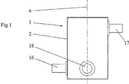
図1〜図3は、板形の熱交換器1を示している。板形の熱交換器1は、外側の筐体2と、筐体2の内部に配置されている板パッケージ3とを有している。板パッケージ3は、互いに積み重ねられて取り付けられている多数の熱交換板4を有している。
1 to 3 show a plate-shaped
板4は、各板4の主要な延長平面pの法線と平行に延びている中心回転軸xを有している。全ての板4は、実質的に同一であり、かつ開示されている例では4つの角を有している実質的な正方形である。板4は、他の多角形や円形の形状であってもよいことに留意されたい。板4は、板4の外側の輪郭が、第1の回転位置と、90°回転後の第2の回転位置とにおける、仮想的な静止した輪郭に一致するように軸xを中心として回転可能である。
The
板4の各々は、図4に示すように、山と谷とからなるひだを有している、熱交換表面5を有している。板4の各々は、また、板4を取り囲んで延びている縁と、その縁の領域の内側で熱交換表面5の周囲に延びている実質的に線の形状または面の形状の縁領域6を有している。開示されている例では、縁により、4つの側縁7’,7”が形成されている。それらの側縁のうちの、2つの側縁7’は、互いに平行であり、かつ、第1の方向に、この側縁7’と平行に縁領域6内を延びているそれぞれの折り曲げ線に沿って、下に向けて折り曲げられている。それらの側縁のうちの、2つの側縁7”は、互いに平行であり、かつ、第2の反対の方向に、この側縁7”と平行に縁領域6内を延びている折り曲げの線に沿って、上に向けて折り曲げられている。各板4の各角には、側縁を折り曲げたときに、対角線の方向に沿って板4の延長平面pに実質的に垂直な平面内を延びているタブ8が形成されている。これらのタブ8は、板4と板パッケージ3を筐体2内に取り付けるための取り付け部材として機能している。より具体的には、タブ8は、筐体2の内部空間内のそれぞれの角に配置されている4つの角の支柱9の縦方向の溝内に直接的または間接的に取り付けられている。角の支柱9は、筐体2と板パッケージ3との間の4つの部分空間10を画定するようにも機能する。
Each of the
板パッケージ3内の板4は、1枚おきに回転軸xを中心として90°回転しており、板4は、空間13’,13”が隣接する両板4の間に形成され、かつ板4の第1の側7’が隣接する板4の第2の側縁7”に接触するように、板パッケージ3内に配置されている。図7に示すように、隣接している側縁7’と7”とは、溶接による接合14により、互いに取り付けられている。溶接による接合14は、レーザービーム溶接や電子ビーム溶接によって行うことが可能である。図4〜図7に示すように、空間13’,13”は、多数の第1の空間13’と多数の第2の空間13”とを含んでいる。2つの対向する側から見ると、板パッケージ3は、第1の空間13’に関しては開いていて、第2の空間13”に関しては閉じていることになる。他の2つの対向している側から見ると、板パッケージ3は、第1の空間13’に関しては閉じていて、第2の空間13”に関しては開いていることになる。第1の空間13’は、第1の媒体を板パッケージ3を介して搬送するように構成されており、かつ、第2の空間13”は、第2の媒体を板パッケージ3を介して搬送するように構成されている。
The
板形の熱交換器1は、第1の媒体用の第1の入口16と第1の出口17とを含み、第2の媒体用の第2の入口18と第2の出口19とを含んでいる。板パッケージ3への入口と出口は、板パッケージ3の側部を介して適切に延びている、つまり、熱交換媒体は、板4の主要な延長平面pと実質的に平行な方向に板パッケージ3に流入しかつ板パッケージ3から流出している。開示されている例では、板パッケージ3は、3つの部分パッケージa,b,cを有している。部分パッケージa,b,cは、2つの画定板21,22によって互いに画定されている。板パッケージ3は、たとえば1つ、2つ、4つ、またはそれよりも多い、その他の数の部分パッケージを有していてもよいことに留意されたい。
The plate-shaped
開示されている例では、第1の媒体は、第1の入口16を通して、部分パッケージa内に第1の空間13’への一方の側を通して搬送される。第1の媒体は、反対側を通って部分パッケージaから流出し、部分空間10内に搬送される。部分空間10内では、第1の媒体は、画定板21を通って搬送され、第1の部分空間13’への側を通って部分パッケージb内に搬送される。媒体は、反対側を通って部分パッケージbから流出し、反対側の部分空間10内に流入する。この部分空間10内では、第1の媒体は、第2の画定板22を通って搬送され、第1の部分空間13’への側を通って部分パッケージcに流入する。その後、第1の媒体は、部分パッケージcの反対側、部分空間10、および第2の出口17を通って板形の熱交換器1から流出する。それに対応するようにして、第2の媒体は、第1の入口18内へ流入し、板形の熱交換器1を通り、それから第2の入口19を通って搬送される。第2の媒体はまた、出口19が入口となり、入口18が出口となるように、第1の媒体に対して逆流するように搬送されてもよいことに留意されたい。
In the disclosed example, the first medium is conveyed through the
図4に開示されている例では、熱交換表面5は、山と谷からなるひだを有している第1の領域31と、山と谷からなるひだを有している第2の領域31とを有している。熱交換表面5の両方の領域31,32の谷は、延長平面pまたはその高さに配置されており、熱交換表面5の両方の領域31,32の山は、延長平面pの上方に配置されている。
In the example disclosed in FIG. 4, the
第1の領域31内の山と谷は、第1の方向Aに延びており、第2の領域内の山と谷は、第2の方向Bに延びている。第1の方向Aは、第2の方向Bに対して実質的に垂直である。さらに、第1の方向Aは、板4の対向している2つの角の間を延びている対角線と実質的に平行であり、第2の方向Bは、板4の対向している他の2つの角の間を延びている対角線と実質的に平行である。熱交換表面5の領域31,32の山と谷は、これらの開示されている方向以外の他の方向に沿って延びていてもよいことに留意されたい。第1の領域31における山と谷は、第2の領域32における山と谷に対して垂直に延びている必要はないが、第1の領域31における山と谷は、第2の領域32における山と谷に対して角度を形成することが重要である。熱交換表面5の領域31,32の山と谷は、たとえば、隣接する表面と関連して支持点を形成するためや、板形の熱交換器1を通る流れに影響を与えるために、湾曲した経路に沿って延び、かつ多少の中断や不規則性を有していてもよい。その他の理由で、逸脱したパターンを有している挿入部分が存在していてもよい。
The peaks and valleys in the
第1の領域31の面積は、第2の領域32の面積と実質的に等しい。各領域31,32は、回転軸xに関する板4の第1の回転位置と、回転軸xに関する90°の回転後の板4の第2の回転位置とにおける、仮想的な静止したそれぞれの輪郭と一致する内側および/または外側の輪郭も有している。内側の第2の領域32は、正方形で、同様に正方形の外側の第1の領域31に対して45°回転している。内側の領域32の外側の輪郭は、外側の領域31の内側の輪郭を形成しており、つまり内側の輪郭に一致している。板パッケージ4内では、熱交換表面5の山は、隣接している板4の熱交換表面5の谷に実質的に常に接触しており、この山は、支持点または小さな支持領域が形成されるように、この谷を横切っている。
The area of the
各板4は、縁領域6の内側に、熱交換表面5の周囲を延びている支持領域41を有している。支持領域41はまた、山42と谷43とからなるひだを有している。支持領域41と熱交換表面5との間の境界は、延長平面pまたはその高さに位置している境界線44で明確になっている。支持領域41の谷43は延長平面pの下方に位置し、支持領域41の山42は延長平面pの上方に位置している。
Each
各角の近傍では、支持領域41は、2つの角の間の対角線に実質的に一致する方向に延びている山42または谷43を有している。支持領域41の各尾根42と谷43は、側縁の中央部分に沿って、側縁のうちの1つの内側を、その山42および谷43のもっとも近くに存在している側縁に対して実質的に垂直な方向に延びている。支持領域41の山42と谷43の方向は、角における対角線の方向から中央部分における垂直な方向へと連続して変化する。
Near each corner, the
したがって、図6および図7に示されているように、支持領域41の山42と谷43は、板4の支持領域41内の各谷43が、その下方に位置している板4の支持領域内の山42に接触するように配置されている。このように、山42と谷43の方向に延びている支持線、つまり細長い支持表面が、板パッケージ3内のすべての隣接する板4の間に常に形成されることになる。また、支持領域41は、支持領域41の外側と内側の輪郭が、板パッケージ3内のすべての板4について一致する形状を有している。
Therefore, as shown in FIGS. 6 and 7, the
図8は、第2の実施形態による、2つの領域31,32に分割されている熱交換表面5を有している板4を示している。内側の領域32は、内側の領域32の外側の輪郭の側縁が、外側の領域31の外側の輪郭のうちでもっとも近くに位置している側縁と平行に延びるように配置された正方形に形成されている。
FIG. 8 shows a
図9は、第3の実施形態による、2つの領域31,32に分割されている熱交換表面5を有している板4を示している。内側の領域32は、円の中心点が外側の領域31の中心点に一致するように配置された円形に形成されている。
FIG. 9 shows a
図10は、第4の実施形態による、複数の領域に分割されている熱交換表面5を有している板4を開示している。板4は、2つの主要な領域31,32を有しており、主要な領域の1つである領域31は、中央の正方形の領域33と、各々が各角に配置されている4つの三角形の角領域34とを含んでいる。
FIG. 10 discloses a
図8〜図10による全ての板は図4の板と同様であり、また、各領域31,32,33,34は、回転軸xに関する板4の前述の第1の回転位置と、回転軸xに関する90°の回転後の板4の第2の回転位置とにおける、仮想的な静止したそれぞれの輪郭に一致するそれぞれの外側および/または内側の輪郭を有するように形成されている。複数の領域の1つである領域31、すなわち主要な領域31の総面積は、複数の領域の1つである領域32、すなわち主要な領域32の総面積と実質的に等しい。
All the plates according to FIGS. 8 to 10 are similar to the plate of FIG. 4 and each
図8〜図10では支持領域41が示されていないが、これらの実施形態は、もちろん前述の類の支持領域41を有していてもよいことに留意されたい。
It should be noted that although the
本発明は、開示した実施形態に限定されず、冒頭の特許請求の範囲の範囲内で変形や修正が可能である。 The invention is not limited to the disclosed embodiments, but can be varied and modified within the scope of the appended claims.
本発明は、開示した支持領域41を有していない板にも適用可能であることに留意されたい。
It should be noted that the present invention is also applicable to plates that do not have the disclosed
Claims (24)
前記熱交換板(4)は、第2の方向(B)に延びている複数の山と谷とからなる波形のひだを有する第2の領域(32)を少なくとも含んでおり、前記領域(31〜34)は、前記回転軸(x)に関する前記熱交換板の第1の回転位置と、前記回転軸(x)に関する90°の回転後の前記熱交換板(4)の第2の回転位置とにおける、仮想的な静止した各輪郭にそれぞれ一致する輪郭を有していることを特徴とする、板形の熱交換器用の熱交換板。At least a first region (31, 32, 34) having a corrugated pleat composed of a plurality of peaks and valleys extending in the first direction (A), wherein the heat exchange plate is a method of the heat exchange plate In a heat exchange plate (4) for a plate-shaped heat exchanger (1) having a central rotational axis (x) extending parallel to the line,
The heat exchange plate (4) includes at least a second region (32) having a corrugated pleat composed of a plurality of peaks and valleys extending in the second direction (B), and the region (31). To 34) are a first rotation position of the heat exchange plate with respect to the rotation axis (x) and a second rotation position of the heat exchange plate (4) after 90 ° rotation with respect to the rotation axis (x). The heat exchange plate for a plate-shaped heat exchanger is characterized by having contours respectively corresponding to the virtual stationary contours.
Applications Claiming Priority (2)
| Application Number | Priority Date | Filing Date | Title |
|---|---|---|---|
| SE0104282A SE520702C2 (en) | 2001-12-18 | 2001-12-18 | Heat exchanger plate with at least two corrugation areas, plate package and plate heat exchanger |
| PCT/SE2002/002100 WO2003069249A1 (en) | 2001-12-18 | 2002-11-19 | A heat exchanger plate, a plate pack and a plate heat exchanger |
Publications (3)
| Publication Number | Publication Date |
|---|---|
| JP2005517891A JP2005517891A (en) | 2005-06-16 |
| JP2005517891A5 JP2005517891A5 (en) | 2006-01-05 |
| JP4065435B2 true JP4065435B2 (en) | 2008-03-26 |
Family
ID=20286383
Family Applications (1)
| Application Number | Title | Priority Date | Filing Date |
|---|---|---|---|
| JP2003568328A Expired - Fee Related JP4065435B2 (en) | 2001-12-18 | 2002-11-19 | Heat exchange plate, board package, and plate heat exchanger |
Country Status (12)
| Country | Link |
|---|---|
| US (1) | US7104315B2 (en) |
| EP (1) | EP1456595B1 (en) |
| JP (1) | JP4065435B2 (en) |
| KR (1) | KR100958485B1 (en) |
| CN (1) | CN100397025C (en) |
| AT (1) | ATE330199T1 (en) |
| AU (1) | AU2002354370A1 (en) |
| CA (1) | CA2470257C (en) |
| DE (1) | DE60212443T2 (en) |
| ES (1) | ES2266606T3 (en) |
| SE (1) | SE520702C2 (en) |
| WO (1) | WO2003069249A1 (en) |
Cited By (1)
| Publication number | Priority date | Publication date | Assignee | Title |
|---|---|---|---|---|
| JP2019066051A (en) * | 2017-09-28 | 2019-04-25 | 株式会社日阪製作所 | Plate type heat exchanger |
Families Citing this family (14)
| Publication number | Priority date | Publication date | Assignee | Title |
|---|---|---|---|---|
| US20050061493A1 (en) * | 2003-09-19 | 2005-03-24 | Holtzapple Mark T. | Heat exchanger system and method |
| CA2471969A1 (en) | 2004-06-23 | 2005-12-23 | Lionel Gerber | Heat exchanger for use in an ice machine |
| US7272005B2 (en) * | 2005-11-30 | 2007-09-18 | International Business Machines Corporation | Multi-element heat exchange assemblies and methods of fabrication for a cooling system |
| PL2202476T3 (en) * | 2008-12-29 | 2016-09-30 | Method of manufacturing a welded plate heat exchanger | |
| ES2398973T3 (en) * | 2009-01-12 | 2013-03-25 | Alfa Laval Vicarb | Reinforced Heat Exchanger Plate |
| KR101017328B1 (en) * | 2009-11-13 | 2011-02-28 | 주식회사 엘에치이 | Heat plate used heat exchanger and welding type heat exchanger comprising the heat plate |
| FR2967247B1 (en) * | 2010-11-05 | 2012-11-02 | Mersen France Py Sas | HEAT EXCHANGER HAVING WELD PLATES AND PLATE COMPRISING SUCH AN EXCHANGER |
| CN102620589A (en) * | 2011-01-30 | 2012-08-01 | 睿能太宇(沈阳)能源技术有限公司 | Heat exchange plate sheet of welded plate type heat exchanger |
| KR101377584B1 (en) * | 2012-07-30 | 2014-03-27 | (주)대영공조시스템 | Sensible heat exchangers used in ventilation ducts sensible device settings Device |
| PL401970A1 (en) * | 2012-12-10 | 2014-06-23 | Synertec Spółka Z Ograniczoną Opdowiedzialnością | Thin-walled plate heat exchanger |
| KR101847625B1 (en) | 2015-07-31 | 2018-04-11 | 주식회사 엘에치이 | heat plate for plate type heat exchanger |
| CN105526814B (en) * | 2016-02-03 | 2017-07-28 | 上海板换机械设备有限公司 | Heat exchanger plates, heat exchanger plates for welded type plate type heat exchanger are to, plate group and welded type plate type heat exchanger |
| KR101897514B1 (en) | 2016-04-11 | 2018-09-12 | 주식회사 엘에치이 | heat exchanger plate for plate type heat exchanger |
| KR101971934B1 (en) | 2017-09-29 | 2019-04-24 | 전희준 | Sensible heat exchanger for ventilation duct |
Family Cites Families (20)
| Publication number | Priority date | Publication date | Assignee | Title |
|---|---|---|---|---|
| US3568765A (en) * | 1968-11-18 | 1971-03-09 | Basf Ag | Plate-type heat exchanger |
| GB1339542A (en) * | 1970-03-20 | 1973-12-05 | Apv Co Ltd | Plate heat exchangers |
| DE2905732C2 (en) * | 1979-02-15 | 1985-07-11 | Interliz Anstalt, Vaduz | Plate heat exchanger |
| SE431793B (en) * | 1980-01-09 | 1984-02-27 | Alfa Laval Ab | PLATE HEAT EXCHANGER WITH CORRUGATED PLATE |
| AT380739B (en) * | 1984-03-14 | 1986-06-25 | Helmut Ing Fischer | DISASSEMBLABLE PLATE HEAT EXCHANGER AND PRESS TOOL FOR THE PRODUCTION OF HEAT EXCHANGE PLATES OF THIS HEAT EXCHANGER |
| FR2562997B1 (en) * | 1984-04-19 | 1988-09-23 | Vicarb Sa | PLATE HEAT EXCHANGERS AND NEW TYPE OF PLATES FOR PROVIDING SUCH EXCHANGERS |
| SE458805B (en) | 1985-06-06 | 1989-05-08 | Reheat Ab | PLATE HEAT EXCHANGER, EVERY PLATE IS DIVIDED IN THE FOUR AREAS WITH SINCE BETWEEN DIFFERENT DIRECTIONS ON THE CORRUGATIONS |
| FI79409C (en) * | 1987-07-13 | 1989-12-11 | Pentti Raunio | Method for constructing a heat exchanger and according to method t designed heat exchanger. |
| AT393162B (en) | 1987-07-13 | 1991-08-26 | Broeckl Gerhard Ing | Plate heat exchanger with a special profile of the heat exchange (heat transfer) zone |
| SE466171B (en) | 1990-05-08 | 1992-01-07 | Alfa Laval Thermal Ab | PLATTERS WORKS AATMONISONING A PLATHER WAS ASTMINSTERING A DIVISION WAS A DIVISIONALLY DIVISED BY A FAULTY OF A PORTABLE WORTH PREPARING ACHIEVENING, |
| ES2079624T3 (en) * | 1991-07-08 | 1996-01-16 | Apv Baker As | PLATE HEAT EXCHANGER, WITH MULTIPLE WALLS. |
| GB9119727D0 (en) * | 1991-09-16 | 1991-10-30 | Apv Baker Ltd | Plate heat exchanger |
| JP3654669B2 (en) * | 1994-09-28 | 2005-06-02 | 株式会社日阪製作所 | Plate heat exchanger |
| JP3650657B2 (en) * | 1995-09-26 | 2005-05-25 | 株式会社日阪製作所 | Plate heat exchanger |
| US5797450A (en) * | 1996-05-02 | 1998-08-25 | Honda Giken Kogyo Kabushiki Kaisha | Oil cooler for automobiles |
| JP3577863B2 (en) * | 1996-09-10 | 2004-10-20 | 三菱電機株式会社 | Counter-flow heat exchanger |
| WO1998033030A1 (en) * | 1997-01-27 | 1998-07-30 | Honda Giken Kogyo Kabushiki Kaisha | Heat exchanger |
| DK174409B1 (en) * | 1998-01-12 | 2003-02-17 | Apv Heat Exchanger As | Heat exchanger plate with reinforced edge design |
| DE19909881A1 (en) * | 1999-03-06 | 2000-09-07 | Behr Gmbh & Co | Cross-flow heat exchanger of plate stack between cover plates uses knob or pleat forms of stack plates to define flow path between inlet and outlet using oval knobs and specified flow path dimensions. |
| FR2806469B1 (en) * | 2000-03-20 | 2002-07-19 | Packinox Sa | METHOD FOR ASSEMBLING THE PLATES OF A BEAM OF PLATES AND BEAM OF PLATES REALIZED BY SUCH A PROCESS |
-
2001
- 2001-12-18 SE SE0104282A patent/SE520702C2/en unknown
-
2002
- 2002-11-19 AU AU2002354370A patent/AU2002354370A1/en not_active Abandoned
- 2002-11-19 CA CA002470257A patent/CA2470257C/en not_active Expired - Fee Related
- 2002-11-19 US US10/495,894 patent/US7104315B2/en not_active Expired - Fee Related
- 2002-11-19 AT AT02789065T patent/ATE330199T1/en not_active IP Right Cessation
- 2002-11-19 CN CNB028255054A patent/CN100397025C/en not_active Expired - Fee Related
- 2002-11-19 ES ES02789065T patent/ES2266606T3/en not_active Expired - Lifetime
- 2002-11-19 DE DE60212443T patent/DE60212443T2/en not_active Expired - Lifetime
- 2002-11-19 JP JP2003568328A patent/JP4065435B2/en not_active Expired - Fee Related
- 2002-11-19 KR KR1020047009437A patent/KR100958485B1/en not_active IP Right Cessation
- 2002-11-19 WO PCT/SE2002/002100 patent/WO2003069249A1/en active IP Right Grant
- 2002-11-19 EP EP02789065A patent/EP1456595B1/en not_active Expired - Lifetime
Cited By (2)
| Publication number | Priority date | Publication date | Assignee | Title |
|---|---|---|---|---|
| JP2019066051A (en) * | 2017-09-28 | 2019-04-25 | 株式会社日阪製作所 | Plate type heat exchanger |
| JP7001413B2 (en) | 2017-09-28 | 2022-01-19 | 株式会社日阪製作所 | Plate heat exchanger |
Also Published As
| Publication number | Publication date |
|---|---|
| DE60212443T2 (en) | 2007-06-14 |
| SE0104282L (en) | 2003-06-19 |
| CN100397025C (en) | 2008-06-25 |
| WO2003069249A1 (en) | 2003-08-21 |
| SE520702C2 (en) | 2003-08-12 |
| CA2470257A1 (en) | 2003-08-21 |
| SE0104282D0 (en) | 2001-12-18 |
| US7104315B2 (en) | 2006-09-12 |
| KR20040065286A (en) | 2004-07-21 |
| EP1456595B1 (en) | 2006-06-14 |
| KR100958485B1 (en) | 2010-05-17 |
| EP1456595A1 (en) | 2004-09-15 |
| DE60212443D1 (en) | 2006-07-27 |
| US20050011638A1 (en) | 2005-01-20 |
| JP2005517891A (en) | 2005-06-16 |
| ATE330199T1 (en) | 2006-07-15 |
| CA2470257C (en) | 2009-03-24 |
| CN1606682A (en) | 2005-04-13 |
| ES2266606T3 (en) | 2007-03-01 |
| AU2002354370A1 (en) | 2003-09-04 |
Similar Documents
| Publication | Publication Date | Title |
|---|---|---|
| JP4065435B2 (en) | Heat exchange plate, board package, and plate heat exchanger | |
| JP4065432B2 (en) | Heat exchange plate | |
| KR101739734B1 (en) | Embossed Fluid Filter Element | |
| RU2520767C1 (en) | Heat exchange plate and plate-type heat exchanger | |
| JP5037524B2 (en) | Heat conduction plate for plate heat exchanger that evenly distributes load in port area | |
| JP4584524B2 (en) | Plate filler for use in heat transfer plates and plate heat exchangers | |
| KR20070107041A (en) | Heat exchanger | |
| TW200829435A (en) | Three dimensional support structure | |
| EP1899671A1 (en) | A heat exchanger plate, a pair of two heat exchanger plates, and plate package for a plate heat exchanger | |
| KR20160114626A (en) | Heat exchanging board and board-type heat exchanger provided with heat exchanging board | |
| KR970706064A (en) | MICROSTRUCTURES IN AN INTERSECTING ARRANGEMENT with cross-array micro- | |
| US4313494A (en) | Plate heat exchanger | |
| JP2005517891A5 (en) | ||
| JP2005513398A5 (en) | ||
| JPH04227480A (en) | Plate heat exchanger | |
| JPH08271173A (en) | Plate structure of plate type heat exchanger | |
| EP3287731B1 (en) | A heat exchanger plate, and a plate heat exchanger | |
| JP2012509757A (en) | Corrugated packing material and column packed with this packing material | |
| JP2003039390A (en) | Corrugated cardboard blanking die, its manufacturing method, and molding of rule assisting member | |
| JPS6142436A (en) | Fin structure for heat exchanger and manufacture thereof | |
| JPH0556206B2 (en) | ||
| JPH04114412U (en) | filtration element | |
| JPH0462617U (en) |
Legal Events
| Date | Code | Title | Description |
|---|---|---|---|
| A521 | Request for written amendment filed |
Free format text: JAPANESE INTERMEDIATE CODE: A523 Effective date: 20050927 |
|
| A621 | Written request for application examination |
Free format text: JAPANESE INTERMEDIATE CODE: A621 Effective date: 20050927 |
|
| A131 | Notification of reasons for refusal |
Free format text: JAPANESE INTERMEDIATE CODE: A132 Effective date: 20070725 |
|
| A521 | Request for written amendment filed |
Free format text: JAPANESE INTERMEDIATE CODE: A523 Effective date: 20071019 |
|
| TRDD | Decision of grant or rejection written | ||
| A01 | Written decision to grant a patent or to grant a registration (utility model) |
Free format text: JAPANESE INTERMEDIATE CODE: A01 Effective date: 20071205 |
|
| A61 | First payment of annual fees (during grant procedure) |
Free format text: JAPANESE INTERMEDIATE CODE: A61 Effective date: 20080104 |
|
| R150 | Certificate of patent or registration of utility model |
Free format text: JAPANESE INTERMEDIATE CODE: R150 |
|
| FPAY | Renewal fee payment (event date is renewal date of database) |
Free format text: PAYMENT UNTIL: 20110111 Year of fee payment: 3 |
|
| FPAY | Renewal fee payment (event date is renewal date of database) |
Free format text: PAYMENT UNTIL: 20110111 Year of fee payment: 3 |
|
| FPAY | Renewal fee payment (event date is renewal date of database) |
Free format text: PAYMENT UNTIL: 20120111 Year of fee payment: 4 |
|
| FPAY | Renewal fee payment (event date is renewal date of database) |
Free format text: PAYMENT UNTIL: 20130111 Year of fee payment: 5 |
|
| LAPS | Cancellation because of no payment of annual fees |