JP4065027B2 - Myocardial fencing - Google Patents
Myocardial fencing Download PDFInfo
- Publication number
- JP4065027B2 JP4065027B2 JP51344898A JP51344898A JP4065027B2 JP 4065027 B2 JP4065027 B2 JP 4065027B2 JP 51344898 A JP51344898 A JP 51344898A JP 51344898 A JP51344898 A JP 51344898A JP 4065027 B2 JP4065027 B2 JP 4065027B2
- Authority
- JP
- Japan
- Prior art keywords
- long
- duration
- myocardium
- activity
- excitable
- Prior art date
- Legal status (The legal status is an assumption and is not a legal conclusion. Google has not performed a legal analysis and makes no representation as to the accuracy of the status listed.)
- Expired - Lifetime
Links
- 230000002107 myocardial effect Effects 0.000 title claims description 10
- 210000003205 muscle Anatomy 0.000 claims abstract description 37
- 230000000694 effects Effects 0.000 claims description 79
- 210000004165 myocardium Anatomy 0.000 claims description 45
- 230000007774 longterm Effects 0.000 claims description 36
- 210000002216 heart Anatomy 0.000 claims description 29
- 230000000903 blocking effect Effects 0.000 claims description 20
- 241001465754 Metazoa Species 0.000 claims description 13
- 238000011866 long-term treatment Methods 0.000 claims description 13
- 230000002964 excitative effect Effects 0.000 claims description 9
- 210000001519 tissue Anatomy 0.000 claims description 9
- 230000001902 propagating effect Effects 0.000 claims description 8
- 230000004044 response Effects 0.000 claims description 7
- 230000004913 activation Effects 0.000 claims description 5
- 230000001360 synchronised effect Effects 0.000 claims description 5
- 238000004137 mechanical activation Methods 0.000 claims description 4
- 230000024977 response to activity Effects 0.000 claims description 2
- 238000001514 detection method Methods 0.000 claims 2
- 238000012153 long-term therapy Methods 0.000 claims 1
- 238000000034 method Methods 0.000 abstract description 11
- 230000008602 contraction Effects 0.000 abstract description 10
- 210000003540 papillary muscle Anatomy 0.000 description 23
- 241000283973 Oryctolagus cuniculus Species 0.000 description 17
- 230000036982 action potential Effects 0.000 description 9
- 210000004027 cell Anatomy 0.000 description 8
- 238000011282 treatment Methods 0.000 description 8
- 210000000056 organ Anatomy 0.000 description 7
- 230000000747 cardiac effect Effects 0.000 description 6
- 238000002474 experimental method Methods 0.000 description 6
- 230000004118 muscle contraction Effects 0.000 description 6
- 239000000243 solution Substances 0.000 description 6
- 238000010586 diagram Methods 0.000 description 4
- 206010047302 ventricular tachycardia Diseases 0.000 description 4
- XLYOFNOQVPJJNP-UHFFFAOYSA-N water Substances O XLYOFNOQVPJJNP-UHFFFAOYSA-N 0.000 description 4
- 230000009471 action Effects 0.000 description 3
- 206010003119 arrhythmia Diseases 0.000 description 3
- 230000006793 arrhythmia Effects 0.000 description 3
- 239000001110 calcium chloride Substances 0.000 description 3
- 229910001628 calcium chloride Inorganic materials 0.000 description 3
- 230000001413 cellular effect Effects 0.000 description 3
- 230000003111 delayed effect Effects 0.000 description 3
- 230000006870 function Effects 0.000 description 3
- 230000002441 reversible effect Effects 0.000 description 3
- 229920006395 saturated elastomer Polymers 0.000 description 3
- 230000035939 shock Effects 0.000 description 3
- 230000000638 stimulation Effects 0.000 description 3
- 239000011550 stock solution Substances 0.000 description 3
- 208000024891 symptom Diseases 0.000 description 3
- 208000003663 ventricular fibrillation Diseases 0.000 description 3
- 206010002091 Anaesthesia Diseases 0.000 description 2
- 229910021607 Silver chloride Inorganic materials 0.000 description 2
- FAPWRFPIFSIZLT-UHFFFAOYSA-M Sodium chloride Chemical compound [Na+].[Cl-] FAPWRFPIFSIZLT-UHFFFAOYSA-M 0.000 description 2
- 230000037005 anaesthesia Effects 0.000 description 2
- 239000003795 chemical substances by application Substances 0.000 description 2
- 230000002354 daily effect Effects 0.000 description 2
- 230000005684 electric field Effects 0.000 description 2
- 239000000835 fiber Substances 0.000 description 2
- 239000007789 gas Substances 0.000 description 2
- 239000011521 glass Substances 0.000 description 2
- 210000005240 left ventricle Anatomy 0.000 description 2
- 239000000203 mixture Substances 0.000 description 2
- 230000010412 perfusion Effects 0.000 description 2
- 238000002360 preparation method Methods 0.000 description 2
- 230000008569 process Effects 0.000 description 2
- 238000011084 recovery Methods 0.000 description 2
- 210000002435 tendon Anatomy 0.000 description 2
- UXVMQQNJUSDDNG-UHFFFAOYSA-L Calcium chloride Chemical compound [Cl-].[Cl-].[Ca+2] UXVMQQNJUSDDNG-UHFFFAOYSA-L 0.000 description 1
- OKTJSMMVPCPJKN-UHFFFAOYSA-N Carbon Chemical compound [C] OKTJSMMVPCPJKN-UHFFFAOYSA-N 0.000 description 1
- 208000027205 Congenital disease Diseases 0.000 description 1
- 206010010904 Convulsion Diseases 0.000 description 1
- WQZGKKKJIJFFOK-GASJEMHNSA-N Glucose Natural products OC[C@H]1OC(O)[C@H](O)[C@@H](O)[C@@H]1O WQZGKKKJIJFFOK-GASJEMHNSA-N 0.000 description 1
- 241000238631 Hexapoda Species 0.000 description 1
- 238000012404 In vitro experiment Methods 0.000 description 1
- 208000007101 Muscle Cramp Diseases 0.000 description 1
- 208000005392 Spasm Diseases 0.000 description 1
- 229910000831 Steel Inorganic materials 0.000 description 1
- 206010065341 Ventricular tachyarrhythmia Diseases 0.000 description 1
- 238000002679 ablation Methods 0.000 description 1
- 230000002159 abnormal effect Effects 0.000 description 1
- 208000037919 acquired disease Diseases 0.000 description 1
- 238000005273 aeration Methods 0.000 description 1
- QVGXLLKOCUKJST-UHFFFAOYSA-N atomic oxygen Chemical compound [O] QVGXLLKOCUKJST-UHFFFAOYSA-N 0.000 description 1
- 238000011888 autopsy Methods 0.000 description 1
- 210000003050 axon Anatomy 0.000 description 1
- 230000005540 biological transmission Effects 0.000 description 1
- 239000008280 blood Substances 0.000 description 1
- 210000004369 blood Anatomy 0.000 description 1
- 210000004204 blood vessel Anatomy 0.000 description 1
- 230000037396 body weight Effects 0.000 description 1
- 208000006218 bradycardia Diseases 0.000 description 1
- 230000036471 bradycardia Effects 0.000 description 1
- 210000005242 cardiac chamber Anatomy 0.000 description 1
- 206010061592 cardiac fibrillation Diseases 0.000 description 1
- 210000004413 cardiac myocyte Anatomy 0.000 description 1
- 229940030602 cardiac therapy drug Drugs 0.000 description 1
- 238000013194 cardioversion Methods 0.000 description 1
- 238000006243 chemical reaction Methods 0.000 description 1
- 210000000038 chest Anatomy 0.000 description 1
- 239000002131 composite material Substances 0.000 description 1
- 238000010276 construction Methods 0.000 description 1
- 230000036461 convulsion Effects 0.000 description 1
- 230000008878 coupling Effects 0.000 description 1
- 238000010168 coupling process Methods 0.000 description 1
- 238000005859 coupling reaction Methods 0.000 description 1
- 201000010099 disease Diseases 0.000 description 1
- 208000037265 diseases, disorders, signs and symptoms Diseases 0.000 description 1
- 238000002224 dissection Methods 0.000 description 1
- 239000012153 distilled water Substances 0.000 description 1
- 229940079593 drug Drugs 0.000 description 1
- 239000003814 drug Substances 0.000 description 1
- 230000004064 dysfunction Effects 0.000 description 1
- 229920001971 elastomer Polymers 0.000 description 1
- 206010015037 epilepsy Diseases 0.000 description 1
- 230000003203 everyday effect Effects 0.000 description 1
- 239000002360 explosive Substances 0.000 description 1
- 230000002600 fibrillogenic effect Effects 0.000 description 1
- 239000008103 glucose Substances 0.000 description 1
- 229910002804 graphite Inorganic materials 0.000 description 1
- 239000010439 graphite Substances 0.000 description 1
- 210000002837 heart atrium Anatomy 0.000 description 1
- 230000010247 heart contraction Effects 0.000 description 1
- 208000019622 heart disease Diseases 0.000 description 1
- 230000004217 heart function Effects 0.000 description 1
- XLYOFNOQVPJJNP-ZSJDYOACSA-N heavy water Substances [2H]O[2H] XLYOFNOQVPJJNP-ZSJDYOACSA-N 0.000 description 1
- 238000007918 intramuscular administration Methods 0.000 description 1
- 238000007912 intraperitoneal administration Methods 0.000 description 1
- 238000001990 intravenous administration Methods 0.000 description 1
- 238000005342 ion exchange Methods 0.000 description 1
- 239000000463 material Substances 0.000 description 1
- 238000005259 measurement Methods 0.000 description 1
- 210000004379 membrane Anatomy 0.000 description 1
- 239000012528 membrane Substances 0.000 description 1
- VNWKTOKETHGBQD-UHFFFAOYSA-N methane Chemical compound C VNWKTOKETHGBQD-UHFFFAOYSA-N 0.000 description 1
- 238000012544 monitoring process Methods 0.000 description 1
- 210000000663 muscle cell Anatomy 0.000 description 1
- 230000003387 muscular Effects 0.000 description 1
- 208000010125 myocardial infarction Diseases 0.000 description 1
- 229910052760 oxygen Inorganic materials 0.000 description 1
- 239000001301 oxygen Substances 0.000 description 1
- 210000003516 pericardium Anatomy 0.000 description 1
- 239000004033 plastic Substances 0.000 description 1
- 230000000644 propagated effect Effects 0.000 description 1
- 238000005057 refrigeration Methods 0.000 description 1
- 230000003252 repetitive effect Effects 0.000 description 1
- 230000000241 respiratory effect Effects 0.000 description 1
- 230000033764 rhythmic process Effects 0.000 description 1
- 230000001020 rhythmical effect Effects 0.000 description 1
- 210000005241 right ventricle Anatomy 0.000 description 1
- 230000035945 sensitivity Effects 0.000 description 1
- HKZLPVFGJNLROG-UHFFFAOYSA-M silver monochloride Chemical compound [Cl-].[Ag+] HKZLPVFGJNLROG-UHFFFAOYSA-M 0.000 description 1
- 239000011780 sodium chloride Substances 0.000 description 1
- 239000010959 steel Substances 0.000 description 1
- 239000000126 substance Substances 0.000 description 1
- 238000001356 surgical procedure Methods 0.000 description 1
- 230000009897 systematic effect Effects 0.000 description 1
- 230000009885 systemic effect Effects 0.000 description 1
- 238000012360 testing method Methods 0.000 description 1
- 238000002560 therapeutic procedure Methods 0.000 description 1
- 210000000779 thoracic wall Anatomy 0.000 description 1
- 238000000108 ultra-filtration Methods 0.000 description 1
- 238000005303 weighing Methods 0.000 description 1
Images


Classifications
-
- A—HUMAN NECESSITIES
- A61—MEDICAL OR VETERINARY SCIENCE; HYGIENE
- A61N—ELECTROTHERAPY; MAGNETOTHERAPY; RADIATION THERAPY; ULTRASOUND THERAPY
- A61N1/00—Electrotherapy; Circuits therefor
- A61N1/18—Applying electric currents by contact electrodes
- A61N1/32—Applying electric currents by contact electrodes alternating or intermittent currents
- A61N1/36—Applying electric currents by contact electrodes alternating or intermittent currents for stimulation
- A61N1/362—Heart stimulators
- A61N1/365—Heart stimulators controlled by a physiological parameter, e.g. heart potential
- A61N1/36514—Heart stimulators controlled by a physiological parameter, e.g. heart potential controlled by a physiological quantity other than heart potential, e.g. blood pressure
- A61N1/36564—Heart stimulators controlled by a physiological parameter, e.g. heart potential controlled by a physiological quantity other than heart potential, e.g. blood pressure controlled by blood pressure
-
- A—HUMAN NECESSITIES
- A61—MEDICAL OR VETERINARY SCIENCE; HYGIENE
- A61N—ELECTROTHERAPY; MAGNETOTHERAPY; RADIATION THERAPY; ULTRASOUND THERAPY
- A61N1/00—Electrotherapy; Circuits therefor
- A61N1/18—Applying electric currents by contact electrodes
- A61N1/32—Applying electric currents by contact electrodes alternating or intermittent currents
- A61N1/36—Applying electric currents by contact electrodes alternating or intermittent currents for stimulation
- A61N1/362—Heart stimulators
- A61N1/3627—Heart stimulators for treating a mechanical deficiency of the heart, e.g. congestive heart failure or cardiomyopathy
-
- A—HUMAN NECESSITIES
- A61—MEDICAL OR VETERINARY SCIENCE; HYGIENE
- A61N—ELECTROTHERAPY; MAGNETOTHERAPY; RADIATION THERAPY; ULTRASOUND THERAPY
- A61N1/00—Electrotherapy; Circuits therefor
- A61N1/18—Applying electric currents by contact electrodes
- A61N1/32—Applying electric currents by contact electrodes alternating or intermittent currents
- A61N1/36—Applying electric currents by contact electrodes alternating or intermittent currents for stimulation
- A61N1/362—Heart stimulators
- A61N1/3628—Heart stimulators using sub-threshold or non-excitatory signals
-
- A—HUMAN NECESSITIES
- A61—MEDICAL OR VETERINARY SCIENCE; HYGIENE
- A61B—DIAGNOSIS; SURGERY; IDENTIFICATION
- A61B17/00—Surgical instruments, devices or methods
- A61B17/00234—Surgical instruments, devices or methods for minimally invasive surgery
- A61B2017/00238—Type of minimally invasive operation
- A61B2017/00243—Type of minimally invasive operation cardiac
-
- A—HUMAN NECESSITIES
- A61—MEDICAL OR VETERINARY SCIENCE; HYGIENE
- A61B—DIAGNOSIS; SURGERY; IDENTIFICATION
- A61B17/00—Surgical instruments, devices or methods
- A61B17/02—Surgical instruments, devices or methods for holding wounds open, e.g. retractors; Tractors
- A61B2017/0237—Surgical instruments, devices or methods for holding wounds open, e.g. retractors; Tractors for heart surgery
- A61B2017/0243—Surgical instruments, devices or methods for holding wounds open, e.g. retractors; Tractors for heart surgery for immobilizing local areas of the heart, e.g. while it beats
-
- A—HUMAN NECESSITIES
- A61—MEDICAL OR VETERINARY SCIENCE; HYGIENE
- A61N—ELECTROTHERAPY; MAGNETOTHERAPY; RADIATION THERAPY; ULTRASOUND THERAPY
- A61N1/00—Electrotherapy; Circuits therefor
- A61N1/18—Applying electric currents by contact electrodes
- A61N1/32—Applying electric currents by contact electrodes alternating or intermittent currents
- A61N1/36—Applying electric currents by contact electrodes alternating or intermittent currents for stimulation
- A61N1/362—Heart stimulators
- A61N1/365—Heart stimulators controlled by a physiological parameter, e.g. heart potential
- A61N1/36514—Heart stimulators controlled by a physiological parameter, e.g. heart potential controlled by a physiological quantity other than heart potential, e.g. blood pressure
- A61N1/36557—Heart stimulators controlled by a physiological parameter, e.g. heart potential controlled by a physiological quantity other than heart potential, e.g. blood pressure controlled by chemical substances in blood
-
- A—HUMAN NECESSITIES
- A61—MEDICAL OR VETERINARY SCIENCE; HYGIENE
- A61N—ELECTROTHERAPY; MAGNETOTHERAPY; RADIATION THERAPY; ULTRASOUND THERAPY
- A61N1/00—Electrotherapy; Circuits therefor
- A61N1/18—Applying electric currents by contact electrodes
- A61N1/32—Applying electric currents by contact electrodes alternating or intermittent currents
- A61N1/36—Applying electric currents by contact electrodes alternating or intermittent currents for stimulation
- A61N1/362—Heart stimulators
- A61N1/365—Heart stimulators controlled by a physiological parameter, e.g. heart potential
- A61N1/368—Heart stimulators controlled by a physiological parameter, e.g. heart potential comprising more than one electrode co-operating with different heart regions
Landscapes
- Health & Medical Sciences (AREA)
- Cardiology (AREA)
- Life Sciences & Earth Sciences (AREA)
- Radiology & Medical Imaging (AREA)
- Biomedical Technology (AREA)
- Nuclear Medicine, Radiotherapy & Molecular Imaging (AREA)
- Engineering & Computer Science (AREA)
- Animal Behavior & Ethology (AREA)
- General Health & Medical Sciences (AREA)
- Public Health (AREA)
- Veterinary Medicine (AREA)
- Heart & Thoracic Surgery (AREA)
- Hematology (AREA)
- Hospice & Palliative Care (AREA)
- Physiology (AREA)
- Biophysics (AREA)
- Electrotherapy Devices (AREA)
- Paper (AREA)
- Measuring Pulse, Heart Rate, Blood Pressure Or Blood Flow (AREA)
- Measurement Of The Respiration, Hearing Ability, Form, And Blood Characteristics Of Living Organisms (AREA)
- Measuring And Recording Apparatus For Diagnosis (AREA)
- Measurement And Recording Of Electrical Phenomena And Electrical Characteristics Of The Living Body (AREA)
- Medicines Containing Material From Animals Or Micro-Organisms (AREA)
- Percussion Or Vibration Massage (AREA)
- Advance Control (AREA)
- Compositions Of Oxide Ceramics (AREA)
- Medicines Containing Plant Substances (AREA)
Abstract
Description
【0001】
発明の分野
本発明は医学分野に関するものである。より詳細には、本発明は細胞の電気的な活動(activity)を可逆的にブロックするための手段に関する。特に、本発明は、心筋を包含するさまざまな筋肉の、筋肉としての活動を可逆的にブロックする(以後、「フェンシング(fencing)」とも称する)ための方法および手段に関する。
【0002】
発明の背景
人体の多くの活動は、筋肉の収縮を伴う。例えば、手足の運動、呼吸活動などである。人体の、もっとも複雑で生命に必要欠くべからざる筋肉の活動は、心臓の筋肉の活動である。心臓はポンプとして機能し、必要なときに必要とされるように収縮することによって、体中を巡る血液の流れを制御する。
【0003】
心臓は異なる部分からなり、その部分が別々に、異なるタイミングで収縮して、前記のポンプの働きを可能にしている。心臓の収縮は、化学反応によって細胞レベルで発生する電気的刺激によって制御される。しかしながら、こうした活動、すなわち心筋の収縮のタイミングを、いわゆる「ペースメーカー」により外部から加えられた電気的刺激の作用によって制御することは当業界では周知である。
【0004】
1997年1月8日出願のPCT特許同時係属出願PCT/IL97/00012号(この出願の明細書は引用により本明細書に組み込まれ、該出願の発明者は本発明者でもある)において、心室または心房の少なくとも一部分の収縮力を改変するための方法および装置が記載されており、これは活性化の後遅れて、あらかじめ決められた時間の間非興奮性の電場を印加することを含んでなる。
【0005】
上記PCT特許出願PCT/IL97/00012号、ならびに本出願と同日に出願され、「筋肉の収縮性を制御するための装置および方法」(“Apparatus and Method for Controlling the Contractility of Musles”)という表題を有し、代理人事件番号第4224/WO/97号と同一と見なされる、本出願と同じ出願人による別の同時係属PCT/IL特許出願(この出願の明細書は引用により本明細書に組み込まれる)において、心室または心房(heart chamber)の少なくとも一部分の収縮力を減じるための方法および装置の記載があり、これは活性化後遅れて、あらかじめ決められた時間の間、非興奮性の電場を印加することを含んでなる。収縮性を低下させることができることは、さまざまな状況において、例えば、手術中や、心筋梗塞後に心臓の不活発な領域を治療するために、重要である。
【0006】
興奮性細胞の機械的活動は、電気的活動に直接結びついている。このことは心臓の活動においてもっとも明白であって、心臓は、ペーシング(pacing)、心筋のさまざまな領域の収縮、ならびに、さまざまなゾーンの系統立った連続的な、または同時に起こる収縮の原因となる、比較的複雑な電気的作用を有する。この細胞の電気的作用のいかなる障害も、細胞の機械的活動に重大な影響を及ぼし、これを止めることさえあり得る。また、刺激の伝達の問題は、さまざまな先天的および後天的疾病に関わる。こうした現象についての詳細な議論は、例えばDonald M.Bers著の本である「興奮収縮連関と心臓収縮力」(“Excitation−Contraction Coupling and Cardiac contractile Force”),Kluwer Academic Publishers,Dordrecut,Boston,London,1993に見ることができる。
【0007】
細胞の電気的な機能不全の治療は主として、薬による治療のような全身性の治療に限定され、あるいは心臓病の一部の症例では、ペースメーカーが必要な場合がある。局所治療、例えば局所剥離も時々試みられる。しかしながら、問題に関わる筋肉の活動を適切な期間、可逆的な方法で完全にブロックしない限り、局所治療では治療することができない症状がいくつか存在する。こういった病気の一例は、心室細動や心室頻拍不整脈であり、これらは罹患しやすい領域に局在する異常な活動によって引き起こされる。
【0008】
心臓治療におけるもう一つの重要な手段は、除細動器の利用である。除細動は、電気的装置が心臓に電気的ショックを伝えることによって、正常に機能しなくなった心臓において、正常な収縮リズムを回復するのを助けるプロセスである。除細動器は体外でも体内(埋め込みまたは挿入)にあってもよい。一般的には、除細動器は徐脈、心室頻拍(VT)、急速心室頻拍(FVT)および心室細動の症状の発現を自動的に検出するように設計されている。不整脈が検出されると、その装置はプログラムされたペーシング、電気的除細動または除細動治療を加える。この装置は一般的に、埋め込み式の二つの電極を有する。除細動器は、上記のように、電気的ショックを加えることによって不整脈を止めるが、これは苦痛を伴う、有害な処置であって(特にしばしば繰り返す場合には)、重要なことは、それが局所処置でなく、むしろ心筋全体に加えられるということである。
【0009】
今回驚くべきことに、筋肉のような細胞の局所的領域の活動を可逆的な方法でブロックすること(すなわち「フェンシング」を行なうこと)、さらにこのようにして必要とする時間だけ細胞の活動をブロックすることが可能であることが発見された。これは本発明の目的とするところである。
【0010】
本発明の目的は、電気的活動を示す目的の組織領域のフェンシングを行ない、それによって一時的かつ可逆的に上記領域の活動をブロックするための装置を提示することである。
【0011】
さらに、本発明の目的は、組織の電気的活動を一時的にブロックすることによって治療することができる症状に罹患した患者を治療するための方法を与えることである。
【0012】
例えば癲癇、不整脈のようなさまざまな症状の治療、痙攣を止めること、およびショックのない除細動に活かすことができる、治療に有用な方法および装置を提示することも、本発明の目的である。
【0013】
本発明の他の目的および利点は、説明を進めるにしたがって明らかになるであろう。
【0014】
発明の要約
ある態様において、本発明は、心筋の電気的活動をブロックするための装置であって、前記心筋の近傍に配置されうる1以上の電極と、
前記心筋の近傍に存在する少なくとも二点の間に長期非興奮性電位(LNT)を生じさせるための回路(circuitry)と、を含み、
前記装置は、人間又は動物の体内に埋め込み可能で、前記心筋の活動をブロックすることによって長期治療を可能とするものであり、
前記回路は、伝播性の活動電位を引き起こさないように、前記長期非興奮性電位の大きさとタイミングを制御することによって、前記長期治療を提供することを可能とし、前記タイミングは、前記心筋の局所的活動化に遅れて前記長期非興奮性電位を印加することを含む、装置に関する。
【0015】
本発明の望ましい実施態様によれば、該装置はさらに、前記心筋の活動を検知するための1以上の検知手段を備え、
前記装置は、前記検知手段によって検知された活動に応答して、前記回路を用いて、前記心筋の前記電気的活動をブロックし、前記長期非興奮性電位の大きさとタイミングを制御する。本発明の別の望ましい実施態様によれば、前記長期非興奮性電位を生じさせるための回路は、所定の周波数で複数の連続したパルスを生成するためのパルス生成手段を有し、前記複数の連続したパルスの総持続時間は、前記長期非興奮性電位の持続時間を構成する。本発明の別の望ましい実施態様によれば、前記の少なくとも二点の間に生じる電位の持続時間を制御するための回路を含んでなる。本発明の別の望ましい実施態様によれば、前記電位の開始時間および/または持続時間を制御するための回路が心臓の活動と同期する。本発明の別の望ましい実施態様によれば、前記電位の開始時間および/または持続時間を制御するための回路が心臓の各拍動毎に作動するわけではない。本発明の別の望ましい実施態様によれば、前記電位の開始時間および/または持続時間を制御するための回路が1、2、または3回の心臓の拍動毎に作動する。
【0016】
また、本発明は、心筋の電気的活動をブロックするための装置であって、
前記心筋の近傍に配置されうる1以上の電極と、
前記心筋の近傍に存在する少なくとも二点の間に長期非興奮性電流が流れるようにするための回路と、を含み、
前記装置は、人間又は動物の体内に埋め込み可能で、前記心筋の活動を治療的にブロックすることによって長期治療を可能とするものであり、
前記回路は、伝播性の活動電位を引き起こさないように、前記長期非興奮性電流の大きさとタイミングを制御することによって、前記長期治療を提供することを可能にし、前記タイミングは、前記心筋の局所的活動化に遅れて前記長期非興奮性電流を印加することを含む、装置に関する。
【0017】
本発明の望ましい実施態様によれば、該装置は前記の少なくとも二点の間に流れる電流の持続時間を制御するための回路を含んでなる。本発明の別の望ましい実施態様によれば、該装置はさらに、前記心筋の活動を検知するための1以上の検知手段を備え、
前記装置は、前記検知手段によって検知された活動に応答して、前記回路を用いて前記心筋の前記電気的活動をブロックし、前記長期非興奮性電流の大きさとタイミングを制御する。本発明の別の望ましい実施態様によれば、前記回路は、所定の周波数で複数の連続したパルスを生成するためのパルス生成手段を有し、前記複数の連続したパルスの総持続時間は、前記長期非興奮性電流の持続時間を構成する。本発明の別の望ましい実施態様によれば、電流の開始時間および/または持続時間を制御するための回路が心臓の活動と同期する。本発明の別の望ましい実施態様によれば、電流の開始時間および/または持続時間を制御するための回路が心臓の各拍動毎に作動するわけではない。本発明の別の望ましい実施態様によれば、電流の開始時間および/または持続時間を制御するための回路が1、2、または3回の心臓の拍動毎に作動する。
【0018】
また、本発明は、心筋の電気的活動をブロックするための装置であって、
前記心筋の近傍に存在する少なくとも二点の間に、伝播性の活動電位を引き起こさない大きさとタイミングを有する電位を生じさせるための手段と、
前記の少なくとも二点の間に非興奮性電流が流れるようにし、それによって長期非興奮性電気シグナルを発生させるための手段と、
長期非興奮性電気シグナルの総持続時間が組織の電気的活動をブロックする閾値を超えるように、前記の少なくとも二点の間に流れる電流の開始時間、持続時間および大きさを制御するための手段と、を含み、
前記装置は、人間又は動物の体内に埋め込み可能で、前記電気的活動をブロックすることによって長期治療を可能とするものであり、前記電流は、前記心筋の局所的活動化に遅れて印加される、装置に関する。
【0019】
また、本発明は、心筋の筋肉活動をブロックするための装置であって、
心筋の近傍に存在する少なくとも二点の間に、伝播性の活動電位を引き起こさない大きさとタイミングを有する電位を生じさせるための手段と、
前記の少なくとも二点の間に非興奮性電流が流れるようにし、それによって長期非興奮性電気シグナルを発生させるための手段と、
長期非興奮性電気シグナルの総持続時間が前記筋肉の機械的活動がブロックされる閾値を超えるように、前記の少なくとも二点の間に流れる電流の開始時間、持続時間および大きさを制御するための手段と、を含み、
前記装置は、人間又は動物の体内に埋め込み可能で、前記筋肉活動をブロックすることによって長期治療を可能とするものであり、前記シグナルは、前記心筋の局所的活動化に遅れて印加される、装置に関する。
【0020】
本発明の望ましい実施態様によれば、前記心筋の近傍に存在する前記の少なくとも二点の間に流れる電流の開始時間、持続時間および大きさを制御するための手段が、所定の周波数を有する複数の連続したパルスを発生させるためのパルス発生手段を含んでなり、但し、前記パルスのタイミングは組織の活動に適合し、かつ前記複数の連続したパルスの総持続時間が長期非興奮性シグナルの持続時間となる。本発明の別の望ましい実施態様によれば、前記電流は直流電流であり、
前記装置は、所定の周波数および振幅を有する1以上の波形を直流シグナルに重ねるための手段をさらに含んでなる。
【0021】
当業者には明らかなように、LNT−シグナルは筋肉の活動に対して遅れるように時間を調節しなければならない。もしこれを考慮に入れないと、結果的に心身に有害な影響が生じる可能性がある。例えば、心筋を処置した場合、適切でないタイミングの電気シグナルによって細動が引き起こされる可能性がある。さらに、LNT−シグナルは通常、多数の短ピークからなり、所定の周波数で印加され、この短ピークが印加される時間の長さの総計が、LNT−シグナルの総持続時間となる。上記の要求に対処するために、本発明の1つの実施形態では、心筋の近傍に存在する少なくとも二点の間に流れる電流の開始時間、持続時間、および大きさを制御するための手段は、所定の周波数の多数のパルスを発生させるためのパルス発生手段を含んでなり、ここにおいてこのパルスのタイミングは、組織の活動に適合し、上記の連続するパルスの総持続時間が長期非興奮性シグナルの持続時間となる。
【0022】
本発明の文脈においては、「長期非興奮性電流」、または「長期非興奮性電位」、または「長期非興奮性シグナル」とは、筋肉細胞内で伝播性の活動電位を引き起こさないシグナル(この活動電位は新たなペーシングや筋肉の収縮を開始させることが可能である)を指すことを意味する。言い換えれば、非興奮性電気パルスによって生じた非興奮性電気刺激は、心筋細胞において伝播性の活動電位を誘起しない刺激である。むしろ、このようなパルスは、心筋の選択されたセグメントにおける細胞の電気的特性に影響を与えることによって、心筋の活動電位への応答に影響を与える。
【0023】
上記PCT特許出願PCT/IL97/00012号に記載のように、直流電流は通常非興奮性シグナルに対するベースラインとして用いられるが、例えば様々な包絡線を有する波形を生じるように直流ベースシグナルの上に交流電流を重ねることによって生じるシグナルのような、複合したシグナルであるシグナルを供給することもできる。当業者には明らかなように、例えば矩形波や正弦波のようないかなる波形を有する、いかなる適当なシグナルをも、重ね合わせることができる。このように、本発明の望ましい実施態様によれば、該装置はさらに直流シグナルに所定の周波数および振幅を有する一または二以上の波形を重ねるための手段を含んでなり、それによって複雑なシグナルをつくり出すことができる。
【0024】
この装置は、特定の要件に応じて、様々な形で提供することができる。本発明を実施するために適した装置の一例は、「心臓拍出量制御装置」(“Cardiac Output Controller”)と題された、この出願と同日出願で、代理人事件番号第27068号と同一と見なされ、本出願と同一の出願人による同時係属PCT特許出願(その記載は引用により本明細書に組み込まれる)において詳細に説明され、権利請求されている。適当な装置の別な例は、ペースメーカー装置に連結されているが、「心臓拍出量増強ペースメーカー」(“Cardiac Output Enhanced Pacemaker”)と題され、この出願と同日に出願され、代理人事件番号第27181号と同一と見なされ、本出願と同一の出願人による別の同時係属PCT特許出願(その記載は引用により本明細書に組み入れられる)の主題である。しかしながら、前述のように、本発明は、発明を実施するために使用される装置のいかなる特別な構成にも限定されるものではない。
【0025】
本発明の望ましい実施態様によれば、該装置は長期間の治療用を意図しており、挿入可能な装置である。挿入可能な装置とは、長期間の治療のために、一定の限られた期間(すなわち二、三週間まで)にわたって導入可能な装置である。無期限に、または非常に長期間、患者が保持することを意図していないので、これは埋め込み式の装置とは異なる。別の望ましい実施態様によれば、該装置は植え込むことが可能である。発明のさらに別の望ましい実施態様によれば、目的とする治療期間が短期であるか長期であるかに関わらず、該装置は、体外式(extra corporal)の装置である。
【0026】
上記で説明したように、非興奮性直流(DC)電流が流れるようにするための手段は、心臓の活動に同期することが望ましい。本発明の望ましい態様によれば、非興奮性直流電流が流れるようにするための手段は、心臓の毎回の拍動時に作動するわけではなく、例えば、1、2、または3回の心拍ごとに作動する。
【0027】
当業者には理解されるように、実際に使用する作動パラメーターのセット(電流、パルスの長さ、電極の数、ペーシングシグナル後のラグ、など)は、本発明を利用する固有の使用状況によって決まり、当業者は容易にある適用に対して最適なパラメーターのセットを案出することができる。ペースメーカーを使用しない場合には、遅延時間は患者の心臓の自然な活動から、または局所の電気的活動から算出することが望ましい。
【0028】
本発明は制御手段に連結した検知手段を用いて便利に実施することができるが、この装置は、筋肉の電気的活動を感知して、適当な時間にLNTシグナルを作動させる。
【0029】
さらに、上記の議論および下記の実施例において、心筋を特に強調したが、これは例証するためにのみ強調されたのであり、本発明はいかなる場合にも決して心筋に限定されることを意図しないことに注目すべきである。それどころか、本発明は電気シグナルに依存する活動を有する他の組織に適用可能である。
【0030】
様々な電極を使用することができ、本発明はいかなるタイプの電極にも決して限定されることはないが、なかでもこの目的に望ましく好適な電極には、例えば炭素電極がある。
【0031】
図面の簡単な説明
本発明の上記およびその他の特徴および利点は、以下の望ましい実施態様の詳細な説明によって、添付図面を参照して、より容易に明らかになる。ここにおいて:
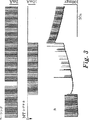
第1図から第7図までは、さまざまな条件下でLNT−シグナルをウサギ乳頭筋に印加したことの影響を示す。
第8図は本発明の一実施態様にしたがった装置の模式図である。
【0032】
定義
下記の用語および略号はこの明細書を通じて使用されるが、明確にするために以下に定義する:
I.M.=筋肉内の
IV=静脈内の
LV=左心室
RV=右心室
VF=心室細動
【0033】
望ましい実施態様の詳細な説明
ここで本発明を詳細な実験によって例証することとする。in vitro実験は、単離されたウサギ乳頭筋を用いて行なったが、これを単離するための手順は下記に詳述する。
【0034】
装置
明確化のために、以下に言及する次の装置についてここで簡単に説明する:
【0035】
プラグシスシステム:プラグシスシステムは、自動記録器およびコンピューターに接続して、測定、制御、およびデータ処理するためのモジュールに組み込むプラグである。通常、これは、生物学的なシグナル測定の感度を高める増幅器として機能する。本文に記載された実験に用いられた、こうした装置の一つは、ドイツのHSE製である。
【0036】
ミラー:この装置(米国Millar Instruments製)は、バッテリー作動性ブリッジ(これはインターフェイスボックスである)に接続可能な微差圧力計変換器であり、その出力は、A/Dコンバーターを用いてデジタル化することができる。別の作動モードにおいては、変換器はDBA(プラグシスDCブリッジ増幅器)を介して接続されるが、DBAは圧力を測定するために変換器に接続される増幅器(ドイツHSE製)である。
【0037】
乳頭筋の単離方法
動物:イスラエル(Yokneam)から入手したNZW(ニュージーランド白色)ウサギ(雄性)、またはNZWとアルビノウサギ(雄性、AniLab,Rehovot)の雑種をケージ(35x55x65cm)あたり2〜3匹として、自然条件下で室温に保つ。毎日、ドライフードの餌(Rabbit Mix−Code 590)を与え、水は無制限に供給する。ケージと室内は毎日清掃する。
【0038】
用具:
A.溶液調製のために:はかり(Mettler Toledo製、model P8303,最大秤量310g、d=1mg)、マグネティックスターラー(Freed Electric製)、分銅10Kg(d=50g、Moznei Shekel製)、95% O2+5% CO2混合物の入ったガスタンク、圧力調節器、pHメーター(Mettler Toledo製、model 320 PH)、製氷器45 Labotal。
【0039】
解剖箱(HSE,Hugo Sachs Elektronik,ドイツ)、温度制御装置319型を包含するステアードオーガンバス(Steered organ bath)813型(I−18E)、増幅器660型および検定ユニット(HSE)のついた張力変換器F30型、立体鏡(Olympus,日本)、デジタル顕微操作用マニピュレーター(HSE)、マニピュレーター、防振台(TMC,米国)、ファラデーケージ、ファイバーオプティックイルミネーター(HSE)、電流および電圧クランプ増幅器(Axon Instruments,米国)、スティミュレーター(Grass Instruments,米国)、小型ピペット引き抜き具pp−83 モデル(Narishige,日本)、それぞれ10および50mAを供給する電源ISO−10およびISO−50(当研究室製)およびオシロスコープ、20MHz(Gould,England)、コンピューター:Power PC 9500/I50(Apple,米国)、またはPentium,166MHz、データ取得ボード:PCI−MIO−16XE50,16バイト、またはPCI−MIO−16E−2,12バイトボード(National Instrument製)、ソフトウェア:ウィンドウズ用Lab View(National Instrument,米国製)。データ取得および分析プログラムは当研究室製である。このプログラムは、データ取得およびオンライン分析、プログラムにつくることができる実験の実行、プログラムにつくることができるシグナルのアウトプットを包含する。オフライン分析プログラムは、筋肉の痙攣および活動電位の異なるパラメーターを分析する。
【0040】
溶液:
Sigma(イスラエル)から入手した材料を用いてクレブス−ヘンゼライト溶液(KHS)を調製した:0.32g/l KCl(4.5mM)、6.99g/l NaCl(118.0mM)、2.01g/l NaHCO3(24.0mM),0.285g/l MgSO4・7H2O(1.19mM),0.16g/l KH2PO4(1.18mM),2.0g/l グルコース(11.0mM)、および0.37g/l CaCl2・2H2O(2.52mM)、95% O2+5% CO2ガス混合物で20分間通気した後に添加した。
【0041】
溶液の調製:KHS保存溶液(X 20,5 l)を調製するために蒸留水(イオン交換カラム、Zilion,イスラエル、および限外濾過、EasypurLF,イスラエル)を使用する。CaCl2以外の化学物質を使用する。保存溶液は冷蔵の一週間後には廃棄され、毎日の実験のためには、新しい溶液を保存溶液から調製する(5l)。CaCl2を添加し、その溶液を20分間通気し(95% O2/5% CO2)、pH7.4に調整する。室温で通気したKHSをオーガンバス内に保存した乳頭筋の灌流に使用する。
【0042】
麻酔および心臓の摘出:動物をケージから出して体重を測定するためにはかりに乗せる。5ccシリンジと23ゲージの針を用いて、1Vembutal 1−1.2mg/kg体重I.P(腹腔内)で動物を麻酔する。麻酔のレベルは、ピンチに対する動物の反応でチェックした。動物が深く麻酔されたら、胸郭の上の皮膚を切断し、胸壁を切り開いて心臓を露出させる。はさみと鉗子を用いて、心膜を切り、すべての血管を切断することによって心臓を切り取る。切り取り後ただちに、心臓を、氷温状態で酸素飽和KHS中におく。
【0043】
乳頭筋の摘出:心臓を新たに調製した氷冷KHSに移し、次に、氷冷して連続的に酸素飽和させたKHSを入れた解剖箱に移す。心臓をゴム製パッドに虫ピンで固定し、次に、左心室を開いて乳頭筋を露出させる。絹糸(60)を乳頭筋の腱の周りに結紮して、乳頭筋を微少な器具を用いて摘出する。切り出した筋肉(長さ2−3m)をオーガンバスに移し、心臓はさらに別の乳頭筋を切除するために4℃に保つ。
【0044】
ステアード(Steiert)オーガンバス:乳頭筋をオーガンバスに入れ、次に、プラスチックホルダーで箱に固定する。アイソメトリックな条件を与えるために、腱に結びつけた絹糸を張力変換器上の(反対側の)固定したフックに引っかける。乳頭筋は、調節された温度37℃に保持されている酸素飽和KHSで連続的に灌流する(7−12ml/min)。
【0045】
ペーシングおよび刺激:
ペーシング刺激(通常、1Hz,持続時間2ms,および振幅2mA)は、オーガンバスの一部であり筋肉の下に置かれる二つのAg−AgCl電極によって与えられる。電極はAgCl層で被覆されており、灌流の間5mA,5msパルスによって塩素化される。線維のライン(収縮軸)に沿って2−3mm離れた位置にある黒鉛電極(ガラスピペットにはめ込まれた直径0.5mm)を用いて、筋肉の上部に定電流刺激(CCU)を与える。筋肉の長さは、最大アイソメトリック張力に調整し、平衡状態になる時間の30分間そのままにおく。
【0046】
実施例1
一時的で可逆的な電気的ブロック
ウサギ乳頭筋は、1Hzで2mSの持続時間と3mAの振幅(この筋肉について測定された閾値の二倍)を有するペーシングシグナルを用いてペースをとった。このペーシングシグナルに1mS遅れて、998mSの持続時間と5mAの振幅を有するLNTシグナルを印加した。得られた結果を第1図に示す。
【0047】
第1図から、LNTシグナルによって電気的な筋肉の活動がペーシングシグナルに対する反応から全体的にブロックされ、その結果、筋肉の収縮が抑制されたことがわかる。LNTシグナルの印加が終了した後は、筋肉の電気的活動の完全な回復がみられた。
【0048】
実施例2
機械的ブロック
ウサギ乳頭筋は、1Hzで2mSの持続時間と2.2mAの振幅を有するペーシングシグナルを用いてペースをとり、このペーシングシグナルに400mS遅れて、200mSの持続時間と0.5mAの振幅を有するLNTシグナルを印加した。LNTシグナルの極性は実験中に反転させた(LNTシグナルに関しては絶対的な“+”および“−”記号は存在しないため、図面における極性の向きは任意であり、適した極性はそれぞれの特定の場合について設定される)。
【0049】
第2図に示されるように、はじめの逆のシグナルは、興奮性シグナルであるから、このシグナルは対応する収縮を筋肉に引き起こし、そのことはペーシングシグナルに対する応答の間にあるピークによって示され、筋肉の収縮活動のブロックは生じない。しかしながら、極性を第1図にあるように切り替えると、筋肉の活動のブロックが達成される。
【0050】
実施例3
ウサギ乳頭筋は、1Hzで持続時間2mS、3mA振幅のペーシングシグナルを用いてペースをとった。上記のペーシングパラメーターは、この筋肉に収縮を引き起こすために必要な相対的な閾値の2倍である。ペーシングシグナルの1mS後に、998mSの持続時間と15mAの振幅を有するLNTシグナルを印加した。得られた結果を第3図に示す。
【0051】
第3図に示すように、筋肉の活動の全体的なブロックが最初に得られ、次にブロックを免れる状態となったが、それは反復的でなく、これは偶然の実験上の問題によると思われる。図面から明らかなように、作用させるLNTシグナルの振幅をペーシングシグナルの5倍にしても、ペーシングシグナルの停止は、収縮を引き起こさなかった。この結果は、やはり、LNTシグナルが本質的に非興奮性シグナルであり、筋肉の活動を完全にブロックすることを示す。LNTシグナルの終了時に筋肉は正常なリズムの収縮に復帰した。筋肉の収縮に関する残存する影響は、回復中の筋肉に数分間みられる。
【0052】
実施例4
ウサギ乳頭筋は、1Hzで2mSの持続時間および3mAの振幅を有するペーシングシグナルを用いてペースをとった。上記ペーシングパラメーターは、用いられた筋肉の相対的な閾値の2倍である。LNTシグナルはペーシングシグナルの1mS後に印加し、998mSの持続時間と15mAの振幅を有した。得られた結果を第4図に示す。
【0053】
筋肉の活動は、全体的にブロックされた。
【0054】
実施例5
ウサギ乳頭筋は下記のパラメーターを用いてペースをとった:
ペーシング:0.5Hz,2mS持続時間、3.5mA;
および1mSの遅延、1999mS持続時間、15mA,0.5HzでLNTシグナルを印加した。
【0055】
結果は、筋肉の活動の完全なブロックを示し(第5図)、LNTシグナルを止めた後、筋肉が徐々に回復することが観察される。
【0056】
実施例6
以下のパラメーターを用いて、実施例1を繰り返した:
ペーシング:1Hz,2mS持続時間,3mA(三つのパラメーターは、この筋肉について測定された閾値の二倍である);
LNTシグナル:1mS遅延、998mS持続時間、5mA,1Hz。
【0057】
ペーシングシグナルから生じた1回の活動電位の爆発的な電位は、第6図に示すようにペーシングシグナルとLNTシグナルの両方を印加した場合に測定される電位に重なった。LNTシグナルを印加した結果、細胞の活動電位の全体的なブロックが生じたが、これは細胞間電極によって測定された(図面の細い線)。
太い線:ペーシングシグナルだけによって引き起こされる活動電位。
細い線:LNTシグナルを印加した間に膜電位の変化が重なって、新たな活動電位によって、細胞がペーシングシグナルに対して反応できないことを示す。
【0058】
この実験は、LNTシグナルがすべての筋肉の活動をブロックしたことを示す。
【0059】
実施例7
以下のパラメーターを用いて、実施例1を繰り返した:
ペーシング:1Hz,2mS持続時間,3mA(三つのパラメーターは、この筋肉について測定された閾値の二倍である);
LNTシグナル:1mS遅延、998mS持続時間、15mA,1Hz。
【0060】
結果を第7図に示す。LNTシグナル(下向き)を印加した結果、細胞間電極によって測定される筋肉の電気的活動、および筋肉の収縮活動の全体的なブロックが得られた。NTシグナルが終了すると、電位および収縮力は、完全な回復を示す。この結果は、LNTシグナルがすべての機械的および電気的活動をブロックしたことを示す。
【0061】
ここで第8図に言及すると、本発明の実施態様にしたがった装置の模式図が示される。この略図において、心筋の一部Hは、二つの電極E1およびE2に対して近接した位置関係となっており、これら電極の末端はそれぞれR1およびR2の付着位置につけられる。これらの電極は電圧および/または電流をシグナル発生装置Sから受けるが、その構造は慣用のものであり、当業者には周知である。したがってその構造についてここで詳細に説明はしないが、Sはさらに、場合に応じて、自律的な電源または本線(コンセント)に接続された電線PLから電力を受ける。好適な装置の例証となる実例は、例えば、この出願と同日に出願された「心臓拍出量制御装置」(“Cardiac Output Controller”)(代理人事件番号第27068号)および「心臓拍出量増強ペースメーカー」(“Cardiac Output Enhanced Pacemaker”)(代理人事件番号第27181号)と題された前述の同時係属PCT/IL特許出願に見出すことができ、その明細書は引用により本明細書に組み入れる。電気シグナル発生装置Sの機能は制御装置Cによって制御されるが、この制御装置はマイクロプロセッサーであってもよいし、または例えばPCや他のコンピューターのような外部制御装置であってもよい。制御装置Cはシグナル発生装置から発生するシグナルのパラメーター、例えば電流の大きさ、周波数、およびタイミング、を制御するが、あらかじめセットされたパラメーター(例えば、パルス発生の周波数)と、例えば心臓または他のパラメーターを監視する装置からの、もしくはペーシングシグナルを与えるペースメーカーからのフィードバックインプットとの両方を利用することができる。これらのインプットシグナルは、FBとしてひとまとめにして図面中に模式的に指示される。もちろん、装置は簡潔にするために模式的に示したにすぎない。そして、当業者は、容易に、本発明の実施に必要なシグナルを供給するのに適した、多数の異なった種類の装置を案出することができるであろう。
【0062】
上記の説明および実施例は、例証するために与えられたものであって、決して発明を制限することを意図するものではない。本発明において、多くの変法を実施することができる。例えば、多くの異なる組織および異なる症状を治療することができる。さらに、本発明の範囲をまったく超えることなく、異なるLNTシグナルを使用することができる。
【図面の簡単な説明】
【図1】LNT−シグナルをウサギ乳頭筋に印加したことの影響を示す。
【図2】LNT−シグナルをウサギ乳頭筋に印加したことの影響を示す。
【図3】LNT−シグナルをウサギ乳頭筋に印加したことの影響を示す。
【図4】LNT−シグナルをウサギ乳頭筋に印加したことの影響を示す。
【図5】LNT−シグナルをウサギ乳頭筋に印加したことの影響を示す。
【図6】LNT−シグナルをウサギ乳頭筋に印加したことの影響を示す。
【図7】LNT−シグナルをウサギ乳頭筋に印加したことの影響を示す。
【図8】本発明の一実施態様にしたがった装置の模式図である。[0001]
Field of Invention
The present invention relates to the medical field. More particularly, the invention relates to a means for reversibly blocking cellular electrical activity. In particular, the present invention relates to methods and means for reversibly blocking muscular activity of various muscles, including the myocardium (hereinafter also referred to as “fencing”).
[0002]
Background of the Invention
Many activities of the human body involve muscle contraction. For example, exercise of limbs and respiratory activity. The most complex and indispensable muscle activity of the human body is the activity of the heart muscle. The heart functions as a pump and controls the flow of blood through the body by contracting as needed when needed.
[0003]
The heart is made up of different parts that contract separately and at different times to allow the pump to function. Heart contraction is controlled by electrical stimulation that occurs at the cellular level through chemical reactions. However, it is well known in the art to control the timing of such activities, ie, myocardial contraction, by the action of an electrical stimulus applied externally by a so-called “pacemaker”.
[0004]
PCT patent co-pending application PCT / IL97 / 00012 filed Jan. 8, 1997 (the specification of this application is incorporated herein by reference and the inventor of the application is also the inventor). Or a method and apparatus for modifying the contractile force of at least a portion of the atrium is described, including applying a non-excitable electric field for a predetermined period of time after activation. Become.
[0005]
PCT Patent Application No. PCT / IL97 / 00012 and filed on the same day as the present application, entitled “Apparatus and Method for Controlling the Controlling of Muscles”. Another co-pending PCT / IL patent application by the same applicant as this application, which is considered the same as agent case number 4224 / WO / 97, the specification of which is incorporated herein by reference A method and apparatus for reducing the contractile force of at least a portion of the ventricle or heart chamber, which is delayed after activation and is a non-excitable electric field for a predetermined time. Applying. The ability to reduce contractility is important in a variety of situations, for example, to treat inactive areas of the heart during surgery or after myocardial infarction.
[0006]
The mechanical activity of excitable cells is directly linked to electrical activity. This is most evident in heart activity, which causes pacing, contraction of various regions of the myocardium, and systematic sequential or simultaneous contraction of various zones. Have a relatively complex electrical action. Any disturbance of this cell's electrical action can seriously affect the cell's mechanical activity and even stop it. Stimulus transmission problems are also associated with various congenital and acquired diseases. A detailed discussion of these phenomena can be found, for example, in Donald M. et al. A book by Bers, “Excitation-Contraction Coupling and Cardiac Contractor Force”, Kluwer Academic Publishers, Dordrect, Boston, 93. See 93.
[0007]
Treatment of cellular electrical dysfunction is primarily limited to systemic treatment, such as treatment with drugs, or in some cases of heart disease, a pacemaker may be required. Local treatment, such as local ablation, is also sometimes attempted. However, there are several symptoms that cannot be treated with local treatment unless the muscle activity involved is completely blocked in a reversible manner for an appropriate period of time. One example of these diseases is ventricular fibrillation and ventricular tachyarrhythmia, which are caused by abnormal activity localized in susceptible areas.
[0008]
Another important tool in cardiac therapy is the use of defibrillators. Defibrillation is a process that helps the electrical device restore normal contraction rhythm in a heart that has failed normally by delivering an electrical shock to the heart. The defibrillator can be external or internal (implanted or inserted). In general, defibrillators are designed to automatically detect the onset of bradycardia, ventricular tachycardia (VT), rapid ventricular tachycardia (FVT), and ventricular fibrillation symptoms. When an arrhythmia is detected, the device applies programmed pacing, cardioversion or defibrillation therapy. This device generally has two implantable electrodes. Defibrillators stop the arrhythmia by applying an electrical shock, as described above, which is a painful and harmful treatment (especially if it repeats often) and what is important is that Is not a local treatment, but rather is applied to the entire myocardium.
[0009]
Surprisingly this time, block the activity of local areas of cells such as muscles in a reversible way (ie “fencing”), and in this way the activity of the cells for as long as needed. It was discovered that it was possible to block. This is the object of the present invention.
[0010]
It is an object of the present invention to present an apparatus for fencing a target tissue region that exhibits electrical activity, thereby temporarily and reversibly blocking the activity of the region.
[0011]
Furthermore, it is an object of the present invention to provide a method for treating a patient suffering from a condition that can be treated by temporarily blocking the electrical activity of the tissue.
[0012]
It is also an object of the present invention to provide a therapeutically useful method and device that can be used to treat various conditions such as epilepsy, arrhythmia, stop convulsions, and defibrillation without shock. .
[0013]
Other objects and advantages of the invention will become apparent as the description proceeds.
[0014]
Summary of invention
In one aspect, the present invention is an apparatus for blocking myocardial electrical activity, comprising one or more electrodes that can be disposed in the vicinity of the myocardium;
A circuit for generating a long-term non-excitatory potential (LNT) between at least two points existing in the vicinity of the myocardium,
The device is implantable in a human or animal body and allows long-term treatment by blocking the activity of the myocardium,
The circuit can provide the long-term treatment by controlling the magnitude and timing of the long-term non-excitable potential so as not to cause a propagating action potential, the timing being local to the myocardium. Application of the long-term non-excitatory potential late to mechanical activation.
[0015]
According to a preferred embodiment of the present invention, the device further comprises one or more sensing means for sensing the activity of the myocardium,
The device uses the circuit to block the electrical activity of the myocardium and control the magnitude and timing of the long-term non-excitable potential in response to the activity detected by the sensing means. According to another preferred embodiment of the present invention, the circuit for generating the long-term non-excitable potential includes pulse generating means for generating a plurality of consecutive pulses at a predetermined frequency, The total duration of consecutive pulses constitutes the duration of the long-term non-excitatory potential. According to another preferred embodiment of the invention, it comprises a circuit for controlling the duration of the potential generated between the at least two points. According to another preferred embodiment of the invention, the circuit for controlling the start time and / or duration of the potential is synchronized with the activity of the heart. According to another preferred embodiment of the invention, the circuit for controlling the start time and / or duration of the potential does not operate for each heart beat. According to another preferred embodiment of the invention, the circuit for controlling the onset time and / or duration of the potential is activated after 1, 2 or 3 heart beats.
[0016]
The present invention also provides a device for blocking myocardial electrical activity,
One or more electrodes that may be disposed in the vicinity of the myocardium;
A circuit for allowing a long-term non-excitable current to flow between at least two points existing in the vicinity of the myocardium,
The device is implantable in the body of a human or animal and enables long-term treatment by therapeutically blocking the activity of the myocardium,
The circuit allows the long-term treatment to be provided by controlling the magnitude and timing of the long-term non-excitable current so as not to cause a propagating action potential, the timing being local to the myocardium. Application of the long-term non-excitable current late to mechanical activation.
[0017]
According to a preferred embodiment of the invention, the device comprises a circuit for controlling the duration of the current flowing between said at least two points. According to another preferred embodiment of the invention, the device further comprises one or more sensing means for sensing the activity of the myocardium,
The device uses the circuit to block the electrical activity of the myocardium and control the magnitude and timing of the long-term non-excitable current in response to activity detected by the sensing means. According to another preferred embodiment of the present invention, the circuit comprises pulse generating means for generating a plurality of consecutive pulses at a predetermined frequency, and the total duration of the plurality of consecutive pulses is Constitutes the duration of long-term non-excitatory currents. According to another preferred embodiment of the present invention, a circuit for controlling the start time and / or duration of the current is synchronized with the heart activity. According to another preferred embodiment of the present invention, the circuit for controlling the start time and / or duration of the current does not operate for each heart beat. According to another preferred embodiment of the present invention, a circuit for controlling the start time and / or duration of the current is activated after every 1, 2 or 3 heart beats.
[0018]
The present invention also provides a device for blocking myocardial electrical activity,
Means for generating a potential having a magnitude and timing that does not cause a propagating action potential between at least two points present in the vicinity of the myocardium;
Means for causing a non-excitable current to flow between said at least two points, thereby generating a long-term non-excitable electrical signal;
Means for controlling the onset time, duration, and magnitude of the current flowing between the at least two points such that the total duration of the long-term non-excitable electrical signal exceeds a threshold that blocks tissue electrical activity And including
The device is implantable in the body of a human or animal and allows long-term treatment by blocking the electrical activity, the current being applied late to local activation of the myocardium , Relating to the device.
[0019]
The present invention also provides a device for blocking myocardial muscle activity,
Means for generating a potential having a magnitude and timing that does not cause a propagating action potential between at least two points in the vicinity of the myocardium;
Means for causing a non-excitable current to flow between said at least two points, thereby generating a long-term non-excitable electrical signal;
To control the start time, duration and magnitude of the current flowing between the at least two points so that the total duration of the long-term non-excitable electrical signal exceeds the threshold at which the mechanical activity of the muscle is blocked Means, and
The device is implantable in the body of a human or animal and allows long-term treatment by blocking the muscle activity, the signal being applied late to local activation of the myocardium, Relates to the device.
[0020]
According to a preferred embodiment of the present invention, the means for controlling the start time, duration and magnitude of the current flowing between the at least two points existing in the vicinity of the myocardium has a plurality of predetermined frequencies. Pulse generating means for generating successive pulses, wherein the timing of the pulses is adapted to tissue activity and the total duration of the plurality of consecutive pulses is the duration of a long-term non-excitable signal It will be time. According to another preferred embodiment of the invention, the current is a direct current,
The apparatus further comprises means for superimposing one or more waveforms having a predetermined frequency and amplitude on the direct current signal.
[0021]
As will be apparent to those skilled in the art, the LNT-signal must be timed to be delayed with respect to muscle activity. If this is not taken into account, the result may be harmful to the mind and body. For example, if the myocardium is treated, fibrillation can be caused by an improperly timed electrical signal. Furthermore, the LNT-signal usually consists of a number of short peaks, which are applied at a predetermined frequency, and the total length of time that this short peak is applied is the total duration of the LNT-signal. To address the above requirements, in one embodiment of the present invention, means for controlling the start time, duration, and magnitude of the current flowing between at least two points in the vicinity of the myocardium include: Comprising pulse generating means for generating a number of pulses of a predetermined frequency, wherein the timing of this pulse is adapted to the activity of the tissue and the total duration of said successive pulses is a long-term non-excitable signal Of duration.
[0022]
In the context of the present invention, a “long-term non-excitable current”, or “long-term non-excitable potential” or “long-term non-excitable signal” is a signal that does not cause a transmitted action potential in muscle cells (this Action potential means that new pacing or muscle contraction can be initiated). In other words, a non-excitable electrical stimulus generated by a non-excitable electrical pulse is a stimulus that does not induce a propagated action potential in cardiomyocytes. Rather, such pulses affect the myocardial response to action potentials by affecting the electrical properties of cells in selected segments of the myocardium.
[0023]
As described in the above PCT patent application PCT / IL97 / 00012, DC current is usually used as a baseline for non-excitable signals, but for example on top of a DC base signal to produce waveforms with various envelopes. It is also possible to supply a signal that is a composite signal, such as a signal generated by superimposing alternating currents. As will be apparent to those skilled in the art, any suitable signal having any waveform, for example a square wave or a sine wave, can be superimposed. Thus, according to a preferred embodiment of the present invention, the apparatus further comprises means for superimposing one or more waveforms having a predetermined frequency and amplitude on the DC signal, thereby generating a complex signal. It can be created.
[0024]
The device can be provided in a variety of forms depending on the particular requirements. An example of a device suitable for practicing the present invention is the same application as this application, entitled “Cardiac Output Controller”, identical to Attorney Case No. 27068. And is described and claimed in detail in a co-pending PCT patent application by the same applicant as the present application, the description of which is incorporated herein by reference. Another example of a suitable device is connected to a pacemaker device, but entitled “Cardiac Output Enhanced Measuremaker”, filed on the same day as this application, and agent case number No. 27181 is the subject of another co-pending PCT patent application (the description of which is incorporated herein by reference) by the same applicant as the present application. However, as noted above, the present invention is not limited to any particular configuration of apparatus used to carry out the invention.
[0025]
According to a preferred embodiment of the invention, the device is intended for long-term treatment and is an insertable device. An insertable device is a device that can be introduced over a limited period of time (ie up to a few weeks) for long-term treatment. This is different from an implantable device because the patient is not intended to be held indefinitely or for a very long time. According to another preferred embodiment, the device can be implanted. According to yet another preferred embodiment of the invention, the device is an extracorporeal device regardless of whether the intended treatment period is short or long.
[0026]
As explained above, it is desirable that the means for allowing non-excitable direct current (DC) current to flow is synchronized to the heart activity. According to a preferred embodiment of the present invention, the means for allowing non-excitable direct current to flow does not operate at every heart beat, for example every 1, 2, or 3 heart beats. Operate.
[0027]
As will be appreciated by those skilled in the art, the actual set of operating parameters used (current, pulse length, number of electrodes, lag after pacing signal, etc.) will depend on the specific use of the invention. The skilled person can easily devise the optimal set of parameters for a given application. If a pacemaker is not used, the delay time is preferably calculated from the patient's natural activity in the heart or from local electrical activity.
[0028]
While the present invention can be conveniently implemented using sensing means coupled to the control means, this device senses muscle electrical activity and activates the LNT signal at an appropriate time.
[0029]
Furthermore, in the above discussion and in the examples below, the myocardium was particularly emphasized, but this was emphasized for illustration only and the present invention is in no way intended to be limited to the myocardium in any way. Should be noted. On the contrary, the present invention is applicable to other tissues having activities that depend on electrical signals.
[0030]
A variety of electrodes can be used and the present invention is in no way limited to any type of electrode, among which electrodes that are desirable and suitable for this purpose include, for example, carbon electrodes.
[0031]
Brief Description of Drawings
The above and other features and advantages of the present invention will be more readily apparent from the following detailed description of preferred embodiments with reference to the accompanying drawings. put it here:
Figures 1 through 7 show the effect of applying an LNT-signal to rabbit papillary muscles under various conditions.
FIG. 8 is a schematic diagram of an apparatus according to one embodiment of the present invention.
[0032]
Definition
The following terms and abbreviations are used throughout this specification, but are defined below for clarity:
I. M.M. = Intramuscular
IV = intravenous
LV = left ventricle
RV = right ventricle
VF = ventricular fibrillation
[0033]
Detailed Description of the Preferred Embodiment
The invention will now be illustrated by detailed experiments. In vitro experiments were performed with isolated rabbit papillary muscles, and the procedure for isolating this is detailed below.
[0034]
apparatus
For clarity, the following equipment referred to below is briefly described here:
[0035]
Plug cis system: A plug-sys system is a plug that plugs into a module for connecting to loggers and computers to measure, control, and process data. Usually this functions as an amplifier that increases the sensitivity of biological signal measurements. One such device used in the experiments described herein is made by HSE, Germany.
[0036]
mirror: This device (Millar Instruments, USA) is a differential pressure gauge transducer that can be connected to a battery-operated bridge (which is an interface box) and its output is digitized using an A / D converter be able to. In another mode of operation, the transducer is connected via a DBA (Pragsys DC Bridge Amplifier), which is an amplifier (made by HSE Germany) that is connected to the transducer to measure pressure.
[0037]
Method for isolating papillary muscle
Animals: Two to three NZW (New Zealand white) rabbits (male) or NZW and albino rabbits (male, AniLab, Rehovot) obtained from Israel (Yokneam) at room temperature under natural conditions Keep on. Every day, dry food bait (Rabbit Mix-Code 590) is given and water is supplied indefinitely. Clean cages and rooms daily.
[0038]
Tools:
A. For solution preparation: scale (Mettler Toledo, model P8303, maximum weighing 310 g, d = 1 mg), magnetic stirrer (Freed Electric),
[0039]
Tension with an autopsy box (HSE, Hugo Sachs Elektronik, Germany), steered organ bath (Steel organ bath) 813 (I-18E), temperature controller 319, amplifier 660 and test unit (HSE) Transducer F30, stereoscope (Olympus, Japan), digital micromanipulator (HSE), manipulator, anti-vibration table (TMC, USA), Faraday cage, fiber optic illuminator (HSE), current and voltage clamp amplifier ( Axon Instruments, USA), Stimulator (Glass Instruments, USA), Small Pipette Extractor pp-83 Model (Narishige, Japan), 10 and 50, respectively Power supplies ISO-10 and ISO-50 (produced by our laboratory) and oscilloscope, 20 MHz (Gould, England), computer: Power PC 9500 / I50 (Apple, USA), or Pentium, 166 MHz, data acquisition board: PCI-MIO-16XE50, 16 bytes, or PCI-MIO-16E-2, 12-byte board (National Instrument), software: Lab View for Windows (National Instrument, USA). The data acquisition and analysis program is from our laboratory. This program includes data acquisition and on-line analysis, running experiments that can be programmed, and output of signals that can be programmed. An off-line analysis program analyzes different parameters of muscle spasm and action potential.
[0040]
solution:
Krebs-Henseleit solution (KHS) was prepared using materials obtained from Sigma (Israel): 0.32 g / l KCl (4.5 mM), 6.99 g / l NaCl (118.0 mM), 2.01 g / l NaHCOThree(24.0 mM), 0.285 g / l MgSOFour・ 7H2O (1.19 mM), 0.16 g / l KH2POFour(1.18 mM), 2.0 g / l glucose (11.0 mM), and 0.37 g / l CaCl2・ 2H2O (2.52 mM), 95% O2+ 5% CO2It was added after aeration with the gas mixture for 20 minutes.
[0041]
Solution preparation: Distilled water (ion exchange column, Zilion, Israel, and ultrafiltration, Easypur LF, Israel) is used to prepare a KHS stock solution (X 20,5 l). CaCl2Use other chemical substances. The stock solution is discarded after one week of refrigeration and a fresh solution is prepared from the stock solution for daily experiments (5 l). CaCl2And aerated the solution for 20 minutes (95% O2/ 5% CO2), And adjust to pH 7.4. KHS aerated at room temperature is used for perfusion of papillary muscles stored in an organ bath.
[0042]
Anesthesia and removal of the heart: Remove the animal from its cage and place it on a scale to measure its weight. Using a 5 cc syringe and a 23 gauge needle, 1 Vembal 1-1.2 mg / kg body weight Animals are anesthetized with P (intraperitoneal). The level of anesthesia was checked by the animal's response to pinch. When the animal is deeply anesthetized, the skin above the rib cage is cut and the chest wall is cut open to expose the heart. Using scissors and forceps, cut the pericardium and cut the heart by cutting all blood vessels. Immediately after excision, the heart is placed in oxygen saturated KHS at ice temperature.
[0043]
Removal of papillary muscles: The heart is transferred to freshly prepared ice-cold KHS, then transferred to a dissection box containing ice-cooled and continuously oxygen-saturated KHS. The heart is fixed to a rubber pad with an insect pin, then the left ventricle is opened to expose the papillary muscle. A silk thread (60) is ligated around the papillary muscle tendon, and the papillary muscle is removed using a small instrument. The excised muscle (length 2-3 m) is transferred to the organ bath and the heart is kept at 4 ° C. to excise another papillary muscle.
[0044]
Steier organ bath: The papillary muscle is placed in the organ bath and then secured to the box with a plastic holder. To provide isometric conditions, a silk thread tied to a tendon is hooked onto a fixed hook (on the opposite side) on the tension transducer. The papillary muscle is continuously perfused with oxygen-saturated KHS maintained at a controlled temperature of 37 ° C. (7-12 ml / min).
[0045]
Pacing and stimulation:
A pacing stimulus (usually 1 Hz, 2 ms duration, and 2 mA amplitude) is provided by two Ag-AgCl electrodes that are part of the organ bath and placed under the muscle. The electrode is coated with an AgCl layer and is chlorinated by a 5 mA, 5 ms pulse during perfusion. Constant current stimulation (CCU) is applied to the upper part of the muscle using a graphite electrode (diameter 0.5 mm fitted in a glass pipette) located 2-3 mm away along the fiber line (contraction axis). The length of the muscle is adjusted to the maximum isometric tension and left for 30 minutes to reach equilibrium.
[0046]
Example 1
Temporary and reversible electrical block
Rabbit papillary muscles were paced with a pacing signal having a duration of 2 mS at 1 Hz and an amplitude of 3 mA (twice the threshold measured for this muscle). An LNT signal having a duration of 998 mS and an amplitude of 5 mA was applied to the pacing signal with a delay of 1 mS. The obtained results are shown in FIG.
[0047]
From FIG. 1, it can be seen that the electrical muscle activity was totally blocked from the response to the pacing signal by the LNT signal, and as a result, the muscle contraction was suppressed. After the application of the LNT signal was completed, complete recovery of muscle electrical activity was observed.
[0048]
Example 2
Mechanical block
Rabbit papillary muscles are paced with a pacing signal having a duration of 2 mS and an amplitude of 2.2 mA at 1 Hz, and an LNT signal having a duration of 200 mS and an amplitude of 0.5 mA, delayed by 400 mS from this pacing signal. Was applied. The polarity of the LNT signal was reversed during the experiment (because there is no absolute “+” and “−” symbol for the LNT signal, the orientation of the polarity in the drawing is arbitrary and the appropriate polarity is Set for the case).
[0049]
As shown in FIG. 2, since the first inverse signal is an excitatory signal, this signal causes a corresponding contraction in the muscle, which is indicated by a peak in response to the pacing signal, There is no block of muscle contraction activity. However, when the polarity is switched as in FIG. 1, a block of muscle activity is achieved.
[0050]
Example 3
Rabbit papillary muscles were paced using a pacing signal with a duration of 2 mS, 3 mA amplitude at 1 Hz. The above pacing parameters are twice the relative threshold required to cause contraction in this muscle. An LNT signal having a duration of 998 mS and an amplitude of 15 mA was applied 1 mS after the pacing signal. The obtained results are shown in FIG.
[0051]
As shown in Figure 3, an overall block of muscle activity was first obtained and then released from the block, but it was not repetitive and this seems to be due to an accidental experimental problem. It is. As is apparent from the figure, stopping the pacing signal did not cause contraction even when the amplitude of the acting LNT signal was 5 times the pacing signal. This result again indicates that the LNT signal is essentially a non-excitable signal and completely blocks muscle activity. At the end of the LNT signal, the muscle returned to normal rhythmic contraction. Residual effects on muscle contraction are seen in the recovering muscle for several minutes.
[0052]
Example 4
Rabbit papillary muscles were paced with a pacing signal having a duration of 2 mS at 1 Hz and an amplitude of 3 mA. The pacing parameter is twice the relative threshold of the muscles used. The LNT signal was applied 1 mS after the pacing signal and had a duration of 998 mS and an amplitude of 15 mA. The obtained results are shown in FIG.
[0053]
Muscle activity was totally blocked.
[0054]
Example 5
Rabbit papillary muscles were paced using the following parameters:
Pacing: 0.5 Hz, 2 mS duration, 3.5 mA;
The LNT signal was applied at a delay of 1 mS, 1999 mS duration, 15 mA, 0.5 Hz.
[0055]
The results show a complete block of muscle activity (FIG. 5) and it is observed that the muscle gradually recovers after the LNT signal is stopped.
[0056]
Example 6
Example 1 was repeated using the following parameters:
Pacing: 1 Hz, 2 mS duration, 3 mA (3 parameters are twice the threshold measured for this muscle);
LNT signal: 1 mS delay, 998 mS duration, 5 mA, 1 Hz.
[0057]
The explosive potential of a single action potential generated from the pacing signal overlapped the potential measured when both the pacing signal and the LNT signal were applied as shown in FIG. Application of the LNT signal resulted in an overall block of cell action potential, which was measured by an intercellular electrode (thin line in the drawing).
Thick line: Action potential caused by pacing signal alone.
Thin line: changes in membrane potential overlap during application of LNT signal, indicating that the new action potential prevents cells from responding to the pacing signal.
[0058]
This experiment shows that the LNT signal blocked all muscle activity.
[0059]
Example 7
Example 1 was repeated using the following parameters:
Pacing: 1 Hz, 2 mS duration, 3 mA (3 parameters are twice the threshold measured for this muscle);
LNT signal: 1 mS delay, 998 mS duration, 15 mA, 1 Hz.
[0060]
The results are shown in FIG. Application of the LNT signal (downward) resulted in an overall block of muscle electrical activity as measured by intercellular electrodes, and muscle contraction activity. When the NT signal ends, the potential and contractile force show a complete recovery. This result indicates that the LNT signal blocked all mechanical and electrical activity.
[0061]
Reference is now made to FIG. 8, which shows a schematic diagram of an apparatus according to an embodiment of the present invention. In this schematic diagram, a part H of the myocardium has a positional relationship close to the two electrodes E1 and E2, and the ends of these electrodes are attached to the attachment positions of R1 and R2, respectively. These electrodes receive voltage and / or current from the signal generator S, but their construction is conventional and well known to those skilled in the art. Therefore, although the structure is not described in detail here, S further receives power from an autonomous power source or an electric wire PL connected to a main line (outlet) as the case may be. Illustrative examples of suitable devices include, for example, “Cardiac Output Controller” (Attorney Incident Number 27068) and “Cardiac Output” filed on the same day as this application. Can be found in the aforementioned co-pending PCT / IL patent application entitled “Cardiac Output Enhanced Producer” (Attorney Case No. 27181), which is incorporated herein by reference. . The function of the electric signal generator S is controlled by the control device C, which may be a microprocessor or an external control device such as a PC or other computer. The controller C controls the parameters of the signal generated from the signal generator, such as the magnitude, frequency and timing of the current, but with preset parameters (eg the frequency of pulse generation) and eg the heart or other Both feedback from devices monitoring parameters or from pacemakers that provide pacing signals are available. These input signals are schematically indicated in the drawing together as an FB. Of course, the device is only shown schematically for the sake of brevity. Those skilled in the art can then easily devise a number of different types of devices suitable for providing the signals necessary to practice the present invention.
[0062]
The above description and examples have been given by way of illustration and are in no way intended to limit the invention. Many variations can be implemented in the present invention. For example, many different tissues and different symptoms can be treated. Furthermore, different LNT signals can be used without exceeding the scope of the present invention.
[Brief description of the drawings]
FIG. 1 shows the effect of applying LNT-signal to rabbit papillary muscle.
FIG. 2 shows the effect of applying LNT-signal to rabbit papillary muscle.
FIG. 3 shows the effect of applying LNT-signal to rabbit papillary muscle.
FIG. 4 shows the effect of applying LNT-signal to rabbit papillary muscle.
FIG. 5 shows the effect of applying LNT-signal to rabbit papillary muscle.
FIG. 6 shows the effect of applying LNT-signal to rabbit papillary muscle.
FIG. 7 shows the effect of applying LNT-signal to rabbit papillary muscle.
FIG. 8 is a schematic diagram of an apparatus according to one embodiment of the present invention.
Claims (18)
前記心筋の近傍に配置されうる1以上の電極と、
前記心筋の近傍に存在する少なくとも二点の間に長期非興奮性電位を生じさせるための回路と、を含み、
前記装置は、人間又は動物の体内に埋め込み可能で、前記心筋の活動をブロックすることによって長期治療を可能とするものであり、
前記回路は、伝播性の活動電位を引き起こさないように、前記長期非興奮性電位の大きさとタイミングを制御することによって、前記長期治療を提供することを可能とし、前記タイミングは、前記心筋の局所的活動化に遅れて前記長期非興奮性電位を印加することを含む、装置。A device for blocking myocardial electrical activity,
One or more electrodes that may be disposed in the vicinity of the myocardium ;
A circuit for generating a long-term non-excitatory potential between at least two points existing in the vicinity of the myocardium ,
The device is implantable in a human or animal body and allows long-term treatment by blocking the activity of the myocardium ,
The circuit can provide the long-term treatment by controlling the magnitude and timing of the long-term non-excitable potential so as not to cause a propagating action potential, the timing being local to the myocardium . Applying the long-term non-excitatory potential in response to mechanical activation.
前記装置は、前記検知手段によって検知された活動に応答して、前記回路を用いて、前記心筋の前記電気的活動をブロックし、前記長期非興奮性電位の大きさとタイミングを制御する、請求項1に記載の装置。And further comprising one or more detection means for detecting the activity of the myocardium ,
The apparatus uses the circuit to block the electrical activity of the myocardium and control the magnitude and timing of the long-term non-excitable potential in response to activity detected by the sensing means. The apparatus according to 1.
前記心筋の近傍に配置されうる1以上の電極と、
前記心筋の近傍に存在する少なくとも二点の間に長期非興奮性電流が流れるようにするための回路と、を含み、
前記装置は、人間又は動物の体内に埋め込み可能で、前記心筋の活動を治療的にブロックすることによって長期治療を可能とするものであり、
前記回路は、伝播性の活動電位を引き起こさないように、前記長期非興奮性電流の大きさとタイミングを制御することによって、前記長期治療を提供することを可能にし、前記タイミングは、前記心筋の局所的活動化に遅れて前記長期非興奮性電流を印加することを含む、装置。A device for blocking myocardial electrical activity,
One or more electrodes that may be disposed in the vicinity of the myocardium ;
A circuit for allowing a long-term non-excitable current to flow between at least two points existing in the vicinity of the myocardium ,
The device is implantable in the body of a human or animal and enables long-term treatment by therapeutically blocking the activity of the myocardium ,
The circuit allows the long-term treatment to be provided by controlling the magnitude and timing of the long-term non-excitable current so as not to cause a propagating action potential, the timing being local to the myocardium . Applying the long-term non-excitable current late in response to mechanical activation.
前記装置は、前記検知手段によって検知された活動に応答して、前記回路を用いて前記心筋の前記電気的活動をブロックし、前記長期非興奮性電流の大きさとタイミングを制御する、請求項8または9に記載の装置。And further comprising one or more detection means for detecting the activity of the myocardium ,
9. The device is responsive to activity detected by the sensing means to block the electrical activity of the myocardium using the circuit to control the magnitude and timing of the long-term non-excitable current. Or the apparatus of 9.
前記心筋の近傍に存在する少なくとも二点の間に、伝播性の活動電位を引き起こさない大きさとタイミングを有する電位を生じさせるための手段と、
前記の少なくとも二点の間に非興奮性電流が流れるようにし、それによって長期非興奮性電気シグナルを発生させるための手段と、
長期非興奮性電気シグナルの総持続時間が組織の電気的活動をブロックする閾値を超えるように、前記の少なくとも二点の間に流れる電流の開始時間、持続時間および大きさを制御するための手段と、を含み、
前記装置は、人間又は動物の体内に埋め込み可能で、前記電気的活動をブロックすることによって長期治療を可能とするものであり、前記電流は、前記心筋の局所的活動化に遅れて印加される、装置。A device for blocking myocardial electrical activity,
Means for generating a potential having a magnitude and timing that does not cause a propagating action potential between at least two points present in the vicinity of the myocardium ;
Means for causing a non-excitable current to flow between said at least two points, thereby generating a long-term non-excitable electrical signal;
Means for controlling the onset time, duration, and magnitude of the current flowing between the at least two points such that the total duration of the long-term non-excitable electrical signal exceeds a threshold that blocks tissue electrical activity And including
The device is implantable in the body of a human or animal and allows long-term treatment by blocking the electrical activity, the current being applied late to local activation of the myocardium ,apparatus.
心筋の近傍に存在する少なくとも二点の間に、伝播性の活動電位を引き起こさない大きさとタイミングを有する電位を生じさせるための手段と、
前記の少なくとも二点の間に非興奮性電流が流れるようにし、それによって長期非興奮性電気シグナルを発生させるための手段と、
長期非興奮性電気シグナルの総持続時間が前記筋肉の機械的活動がブロックされる閾値を超えるように、前記の少なくとも二点の間に流れる電流の開始時間、持続時間および大きさを制御するための手段と、を含み、
前記装置は、人間又は動物の体内に埋め込み可能で、前記筋肉活動をブロックすることによって長期治療を可能とするものであり、前記シグナルは、前記心筋の局所的活動化に遅れて印加される、装置。An apparatus for blocking muscle Nikukatsu movement of the myocardium,
Means for generating a potential having a magnitude and timing that does not cause a propagating action potential between at least two points in the vicinity of the myocardium;
Means for causing a non-excitable current to flow between said at least two points, thereby generating a long-term non-excitable electrical signal;
To control the start time, duration and magnitude of the current flowing between the at least two points so that the total duration of the long-term non-excitable electrical signal exceeds the threshold at which the mechanical activity of the muscle is blocked Means, and
The apparatus is implantable in the human or animal body, which allows for long-term therapy by blocking the muscle Nikukatsu moving, the signal is applied with a delay to the local activity of the heart muscle Equipment.
前記装置は、所定の周波数および振幅を有する1以上の波形を直流シグナルに重ねるための手段をさらに含んでなる、請求項15〜17のいずれか一つに記載の装置。The current is a direct current;
The apparatus according to any one of claims 15 to 17, further comprising means for superimposing one or more waveforms having a predetermined frequency and amplitude on a direct current signal.
Applications Claiming Priority (5)
| Application Number | Priority Date | Filing Date | Title |
|---|---|---|---|
| US2639296P | 1996-09-16 | 1996-09-16 | |
| IL11926196A IL119261A0 (en) | 1996-09-17 | 1996-09-17 | Electrical muscle controller |
| IL119261 | 1996-09-17 | ||
| IL60/026,392 | 1996-09-17 | ||
| PCT/IL1997/000233 WO1998010830A1 (en) | 1996-09-16 | 1997-07-09 | Fencing of cardiac muscles |
Publications (3)
| Publication Number | Publication Date |
|---|---|
| JP2002500521A JP2002500521A (en) | 2002-01-08 |
| JP2002500521A5 JP2002500521A5 (en) | 2007-11-22 |
| JP4065027B2 true JP4065027B2 (en) | 2008-03-19 |
Family
ID=26323305
Family Applications (7)
| Application Number | Title | Priority Date | Filing Date |
|---|---|---|---|
| JP10513446A Pending JP2001501503A (en) | 1996-09-16 | 1997-07-09 | Apparatus and method for controlling muscle contractility |
| JP51344898A Expired - Lifetime JP4065027B2 (en) | 1996-09-16 | 1997-07-09 | Myocardial fencing |
| JP52963797A Pending JP2001506870A (en) | 1996-09-16 | 1997-07-09 | Cardiac output controller |
| JP51344798A Pending JP2001507951A (en) | 1996-09-16 | 1997-07-09 | Drug-device combination for controlling muscle contractility |
| JP52963897A Expired - Lifetime JP4102439B2 (en) | 1996-09-16 | 1997-07-09 | Pacemaker with increased cardiac output |
| JP2007206282A Expired - Lifetime JP4589365B2 (en) | 1996-09-16 | 2007-08-08 | Cardiac output controller |
| JP2008022802A Withdrawn JP2008149161A (en) | 1996-09-16 | 2008-02-01 | Apparatus for heart pacing, and method for operating the apparatus |
Family Applications Before (1)
| Application Number | Title | Priority Date | Filing Date |
|---|---|---|---|
| JP10513446A Pending JP2001501503A (en) | 1996-09-16 | 1997-07-09 | Apparatus and method for controlling muscle contractility |
Family Applications After (5)
| Application Number | Title | Priority Date | Filing Date |
|---|---|---|---|
| JP52963797A Pending JP2001506870A (en) | 1996-09-16 | 1997-07-09 | Cardiac output controller |
| JP51344798A Pending JP2001507951A (en) | 1996-09-16 | 1997-07-09 | Drug-device combination for controlling muscle contractility |
| JP52963897A Expired - Lifetime JP4102439B2 (en) | 1996-09-16 | 1997-07-09 | Pacemaker with increased cardiac output |
| JP2007206282A Expired - Lifetime JP4589365B2 (en) | 1996-09-16 | 2007-08-08 | Cardiac output controller |
| JP2008022802A Withdrawn JP2008149161A (en) | 1996-09-16 | 2008-02-01 | Apparatus for heart pacing, and method for operating the apparatus |
Country Status (7)
| Country | Link |
|---|---|
| US (1) | US6233484B1 (en) |
| EP (5) | EP1011795B1 (en) |
| JP (7) | JP2001501503A (en) |
| AT (2) | ATE463278T1 (en) |
| AU (5) | AU3357197A (en) |
| DE (2) | DE69739833D1 (en) |
| WO (5) | WO1998010831A1 (en) |
Families Citing this family (114)
| Publication number | Priority date | Publication date | Assignee | Title |
|---|---|---|---|---|
| IL125424A0 (en) | 1998-07-20 | 1999-03-12 | New Technologies Sa Ysy Ltd | Pacing with hemodynamic enhancement |
| US7167748B2 (en) | 1996-01-08 | 2007-01-23 | Impulse Dynamics Nv | Electrical muscle controller |
| US8825152B2 (en) | 1996-01-08 | 2014-09-02 | Impulse Dynamics, N.V. | Modulation of intracellular calcium concentration using non-excitatory electrical signals applied to the tissue |
| US8321013B2 (en) * | 1996-01-08 | 2012-11-27 | Impulse Dynamics, N.V. | Electrical muscle controller and pacing with hemodynamic enhancement |
| JP4175662B2 (en) | 1996-01-08 | 2008-11-05 | インパルス ダイナミクス エヌ.ヴイ. | Electric muscle control device |
| IL119261A0 (en) | 1996-09-17 | 1996-12-05 | New Technologies Sa Ysy Ltd | Electrical muscle controller |
| US9289618B1 (en) | 1996-01-08 | 2016-03-22 | Impulse Dynamics Nv | Electrical muscle controller |
| US6415178B1 (en) | 1996-09-16 | 2002-07-02 | Impulse Dynamics N.V. | Fencing of cardiac muscles |
| US9713723B2 (en) | 1996-01-11 | 2017-07-25 | Impulse Dynamics Nv | Signal delivery through the right ventricular septum |
| EP1011795B1 (en) | 1996-09-16 | 2010-03-10 | Impulse Dynamics N.V. | Cardiac output controller |
| ZA976112B (en) | 1996-09-16 | 1998-02-10 | New Technologies Sa Ysy Ltd | Apparatus and method for controlling the contractility of muscles. |
| US6463324B1 (en) | 1996-09-16 | 2002-10-08 | Impulse Dynamics N. V. | Cardiac output enhanced pacemaker |
| US7006871B1 (en) | 1997-07-16 | 2006-02-28 | Metacure N.V. | Blood glucose level control |
| EP1779890B8 (en) | 1997-07-16 | 2009-07-08 | Metacure Limited | Smooth muscle controller |
| US6711436B1 (en) | 1997-08-08 | 2004-03-23 | Duke University | Compositions, apparatus and methods for facilitating surgical procedures |
| WO1999007354A2 (en) * | 1997-08-08 | 1999-02-18 | Duke University | Compositions, apparatus and methods for facilitating surgical procedures |
| US6675043B1 (en) | 1998-11-06 | 2004-01-06 | Impulse Dynamics N.V. | Sensor-based regulation of excitable tissue control of the heart |
| US6725093B1 (en) | 1998-11-06 | 2004-04-20 | Impulse Dynamics N.V. | Regulation of excitable tissue control of the heart based on physiological input |
| AU1072100A (en) | 1998-11-06 | 2000-05-29 | Impulse Dynamics N.V. | Trigger-based regulation of excitable tissue control in the heart |
| US6463323B1 (en) | 1998-11-12 | 2002-10-08 | Em Vascular, Inc. | Electrically mediated angiogenesis |
| US6152882A (en) * | 1999-01-26 | 2000-11-28 | Impulse Dynamics N.V. | Apparatus and method for chronic measurement of monophasic action potentials |
| EP1825880B1 (en) | 1999-03-05 | 2016-05-11 | Metacure Limited | Blood glucose level control |
| US8019421B2 (en) * | 1999-03-05 | 2011-09-13 | Metacure Limited | Blood glucose level control |
| US8700161B2 (en) | 1999-03-05 | 2014-04-15 | Metacure Limited | Blood glucose level control |
| US9101765B2 (en) | 1999-03-05 | 2015-08-11 | Metacure Limited | Non-immediate effects of therapy |
| DE60035181T2 (en) | 1999-03-05 | 2008-02-21 | Metacure Ltd. | CONTROL OF THE BLOOD SUGAR MIRROR |
| US8666495B2 (en) | 1999-03-05 | 2014-03-04 | Metacure Limited | Gastrointestinal methods and apparatus for use in treating disorders and controlling blood sugar |
| US6263242B1 (en) | 1999-03-25 | 2001-07-17 | Impulse Dynamics N.V. | Apparatus and method for timing the delivery of non-excitatory ETC signals to a heart |
| US6370430B1 (en) | 1999-03-25 | 2002-04-09 | Impulse Dynamics N.V. | Apparatus and method for controlling the delivery of non-excitatory cardiac contractility modulating signals to a heart |
| US6292704B1 (en) | 1999-05-25 | 2001-09-18 | Impulse Dynamics N. V. | High capacitance myocardial electrodes |
| US6304777B1 (en) | 1999-05-26 | 2001-10-16 | Impulse Dynamics N.V. | Induction of cardioplegia applied electrical signals |
| US6442424B1 (en) | 1999-05-26 | 2002-08-27 | Impulse Dynamics N.V. | Local cardiac motion control using applied electrical signals |
| US8014858B1 (en) | 1999-05-26 | 2011-09-06 | Impulse Dynamics N.V. | Shockless defibrillation |
| US6285906B1 (en) | 1999-05-26 | 2001-09-04 | Impulse Dynamics N. V. | Muscle contraction assist device |
| US6973347B1 (en) | 1999-05-26 | 2005-12-06 | Impulse Dynamics Nv | Local cardiac motion control using applied electrical signals and mechanical force |
| US6223072B1 (en) | 1999-06-08 | 2001-04-24 | Impulse Dynamics N.V. | Apparatus and method for collecting data useful for determining the parameters of an alert window for timing delivery of ETC signals to a heart under varying cardiac conditions |
| US6233487B1 (en) | 1999-06-08 | 2001-05-15 | Impulse Dynamics N.V. | Apparatus and method for setting the parameters of an alert window used for timing the delivery of ETC signals to a heart under varying cardiac conditions |
| US6360126B1 (en) | 1999-08-20 | 2002-03-19 | Impulse Dynamics N.V. | Apparatus and method for controlling the delivery of contractility modulating non-excitatory signals to the heart |
| US6556872B2 (en) | 1999-08-24 | 2003-04-29 | Ev Vascular, Inc. | Therapeutic device and method for treating diseases of cardiac muscle |
| US6560489B2 (en) | 1999-08-24 | 2003-05-06 | Em Vascular, Inc. | Therapeutic device and method for treating diseases of cardiac muscle |
| WO2001030445A1 (en) * | 1999-10-25 | 2001-05-03 | Impulse Dynamics N.V. | Cardiac contractility modulation device having anti-arrhythmic capabilities and a method of operating thereof |
| US6993385B1 (en) | 1999-10-25 | 2006-01-31 | Impulse Dynamics N.V. | Cardiac contractility modulation device having anti-arrhythmic capabilities and a method of operating thereof |
| AU2023201A (en) | 1999-12-29 | 2001-07-16 | Impulse Dynamics N.V. | Field delivery safety system using detection of atypical ecg |
| US6480737B1 (en) | 1999-12-29 | 2002-11-12 | Impulse Dynamics Nv | Field delivery safety system using detection of atypical ECG |
| EP1267992A4 (en) * | 2000-04-06 | 2008-12-10 | Impulse Dynamics Nv | Contractility enhancement using excitable tissue control and multi-site pacing |
| AU5504301A (en) | 2000-05-04 | 2001-11-12 | Impulse Dynamics N.V. | Signal delivery through the right ventricular septum |
| WO2002038062A2 (en) | 2000-11-13 | 2002-05-16 | Boehm Frank H Jr | Device and method for lumbar interbody fusion |
| US7330753B2 (en) | 2001-04-18 | 2008-02-12 | Metacure N.V. | Analysis of eating habits |
| CA2442352A1 (en) * | 2002-09-26 | 2004-03-26 | Reg Macquarrie | Poly-(vinyl alcohol) based meat processing films |
| US9931503B2 (en) | 2003-03-10 | 2018-04-03 | Impulse Dynamics Nv | Protein activity modification |
| US11439815B2 (en) | 2003-03-10 | 2022-09-13 | Impulse Dynamics Nv | Protein activity modification |
| US7840262B2 (en) | 2003-03-10 | 2010-11-23 | Impulse Dynamics Nv | Apparatus and method for delivering electrical signals to modify gene expression in cardiac tissue |
| US7006864B2 (en) * | 2003-06-17 | 2006-02-28 | Ebr Systems, Inc. | Methods and systems for vibrational treatment of cardiac arrhythmias |
| US8792985B2 (en) | 2003-07-21 | 2014-07-29 | Metacure Limited | Gastrointestinal methods and apparatus for use in treating disorders and controlling blood sugar |
| US7292888B2 (en) | 2003-08-11 | 2007-11-06 | Medtronic, Inc. | Cardiac stimulation during a refractory period |
| US7184830B2 (en) * | 2003-08-18 | 2007-02-27 | Ebr Systems, Inc. | Methods and systems for treating arrhythmias using a combination of vibrational and electrical energy |
| US7130687B2 (en) * | 2003-10-24 | 2006-10-31 | Medtronic, Inc | Implantable medical device and method for delivering therapy for sleep-disordered breathing |
| US8352031B2 (en) | 2004-03-10 | 2013-01-08 | Impulse Dynamics Nv | Protein activity modification |
| US11779768B2 (en) | 2004-03-10 | 2023-10-10 | Impulse Dynamics Nv | Protein activity modification |
| WO2006119467A2 (en) | 2005-05-04 | 2006-11-09 | Impulse Dynamics Nv | Protein activity modification |
| US7765001B2 (en) | 2005-08-31 | 2010-07-27 | Ebr Systems, Inc. | Methods and systems for heart failure prevention and treatments using ultrasound and leadless implantable devices |
| EP1835964B1 (en) * | 2004-12-21 | 2016-03-09 | EBR Systems, Inc. | Leadless cardiac system for pacing and arrhythmia treatment |
| WO2006069327A2 (en) | 2004-12-21 | 2006-06-29 | Ebr Systems, Inc. | Implantable transducer devices |
| US7558631B2 (en) * | 2004-12-21 | 2009-07-07 | Ebr Systems, Inc. | Leadless tissue stimulation systems and methods |
| US9821158B2 (en) | 2005-02-17 | 2017-11-21 | Metacure Limited | Non-immediate effects of therapy |
| WO2006087712A2 (en) | 2005-02-17 | 2006-08-24 | Metacure N.V. | Charger with data transfer capabilities |
| WO2006097934A2 (en) | 2005-03-18 | 2006-09-21 | Metacure Limited | Pancreas lead |
| WO2006102626A2 (en) | 2005-03-24 | 2006-09-28 | Metacure Nv | Wireless leads for gastrointestinal tract applications |
| EP1937357B1 (en) | 2005-09-06 | 2023-11-01 | Impulse Dynamics N.V. | Apparatus for delivering electrical signals to a heart |
| US7702392B2 (en) * | 2005-09-12 | 2010-04-20 | Ebr Systems, Inc. | Methods and apparatus for determining cardiac stimulation sites using hemodynamic data |
| US9149638B2 (en) * | 2006-01-30 | 2015-10-06 | Medtronic, Inc. | Method and system for controlling pulmonary capillary pressure |
| US7751888B1 (en) | 2006-08-28 | 2010-07-06 | Pacesetter, Inc. | Systems and methods for delivering stimulation pulses using an implantable cardiac stimulation device |
| US20080114408A1 (en) * | 2006-11-13 | 2008-05-15 | Shuros Allan C | Method and device for simulated exercise |
| WO2008070189A2 (en) | 2006-12-06 | 2008-06-12 | The Cleveland Clinic Foundation | Method and system for treating acute heart failure by neuromodulation |
| US7778707B2 (en) * | 2007-03-21 | 2010-08-17 | Cardiac Pacemakers, Inc. | Method and device for myocardial stress redistribution |
| US8718773B2 (en) | 2007-05-23 | 2014-05-06 | Ebr Systems, Inc. | Optimizing energy transmission in a leadless tissue stimulation system |
| US8972007B2 (en) | 2007-09-25 | 2015-03-03 | Cardiac Pacemakers, Inc. | Variable shortening of AV delay for treatment of cardiac disease |
| US7953493B2 (en) | 2007-12-27 | 2011-05-31 | Ebr Systems, Inc. | Optimizing size of implantable medical devices by isolating the power source |
| WO2009120636A1 (en) * | 2008-03-25 | 2009-10-01 | Ebr Systems, Inc. | Temporary electrode connection for wireless pacing systems |
| US8423130B2 (en) | 2008-05-09 | 2013-04-16 | Metacure Limited | Optimization of thresholds for eating detection |
| US20100016911A1 (en) | 2008-07-16 | 2010-01-21 | Ebr Systems, Inc. | Local Lead To Improve Energy Efficiency In Implantable Wireless Acoustic Stimulators |
| US20100198102A1 (en) * | 2008-09-19 | 2010-08-05 | Terry William Burton Moore | Method and device for reducing muscle tension through electrical manipulation |
| CN102481450B (en) * | 2009-04-07 | 2015-09-16 | 威斯特天主教保健中心 | uterine electrical stimulation system and method |
| US8193220B1 (en) * | 2009-08-20 | 2012-06-05 | Alan Brown Scott | Method of changing muscle lengths with anesthetic drugs |
| WO2011030287A1 (en) | 2009-09-09 | 2011-03-17 | Guy Dori | Methods and apparatus for optimizing cardiac output, preventing backward heart failure, and minimizing diastolic myocardial wall stress by controlling left ventricular filling |
| US8901192B2 (en) | 2009-10-22 | 2014-12-02 | Denki Kagaku Kogyo Kabushiki Kaisha | (Meth)acrylic resin composition |
| US8934975B2 (en) | 2010-02-01 | 2015-01-13 | Metacure Limited | Gastrointestinal electrical therapy |
| US9872983B2 (en) | 2010-10-27 | 2018-01-23 | Dignity Health | Uterine electrical stimulation system and method |
| CA3023152C (en) | 2010-10-27 | 2020-01-07 | Dignity Health | Uterine electrical stimulation system and method |
| JP6030560B2 (en) | 2011-09-14 | 2016-11-24 | デンカ株式会社 | Composition and method for temporarily fixing member using the same |
| WO2013111137A2 (en) | 2012-01-26 | 2013-08-01 | Rainbow Medical Ltd. | Wireless neurqstimulatqrs |
| WO2014087337A1 (en) | 2012-12-06 | 2014-06-12 | Bluewind Medical Ltd. | Delivery of implantable neurostimulators |
| US9446247B2 (en) | 2013-05-21 | 2016-09-20 | Mr3 Medical, Llc | System and method for stimulating the heart using sub-threshold biphasic stimulation |
| SG10201808553QA (en) | 2014-05-22 | 2018-11-29 | Cardionomic Inc | Catheter and catheter system for electrical neuromodulation |
| US10940318B2 (en) * | 2014-06-17 | 2021-03-09 | Morton M. Mower | Method and apparatus for electrical current therapy of biological tissue |
| EP3194017A1 (en) | 2014-09-08 | 2017-07-26 | Cardionomic, Inc. | Methods for electrical neuromodulation of the heart |
| EP3194007B1 (en) | 2014-09-08 | 2018-07-04 | Cardionomic, Inc. | Catheter and electrode systems for electrical neuromodulation |
| JP6445290B2 (en) * | 2014-09-22 | 2018-12-26 | フクダ電子株式会社 | Amplifier |
| US10493278B2 (en) | 2015-01-05 | 2019-12-03 | CARDIONOMIC, Inc. | Cardiac modulation facilitation methods and systems |
| US9764146B2 (en) | 2015-01-21 | 2017-09-19 | Bluewind Medical Ltd. | Extracorporeal implant controllers |
| US10004896B2 (en) | 2015-01-21 | 2018-06-26 | Bluewind Medical Ltd. | Anchors and implant devices |
| US9597521B2 (en) | 2015-01-21 | 2017-03-21 | Bluewind Medical Ltd. | Transmitting coils for neurostimulation |
| US9782589B2 (en) | 2015-06-10 | 2017-10-10 | Bluewind Medical Ltd. | Implantable electrostimulator for improving blood flow |
| US10105540B2 (en) | 2015-11-09 | 2018-10-23 | Bluewind Medical Ltd. | Optimization of application of current |
| US9713707B2 (en) | 2015-11-12 | 2017-07-25 | Bluewind Medical Ltd. | Inhibition of implant migration |
| EP3426338A4 (en) | 2016-03-09 | 2019-10-30 | Cardionomic, Inc. | Cardiac contractility neurostimulation systems and methods |
| US10124178B2 (en) | 2016-11-23 | 2018-11-13 | Bluewind Medical Ltd. | Implant and delivery tool therefor |
| US20180353764A1 (en) | 2017-06-13 | 2018-12-13 | Bluewind Medical Ltd. | Antenna configuration |
| WO2019055434A1 (en) | 2017-09-13 | 2019-03-21 | CARDIONOMIC, Inc. | Neurostimulation systems and methods for affecting cardiac contractility |
| US20200323461A1 (en) | 2017-10-20 | 2020-10-15 | Indian Institute Of Technology, Guwahati | Point-of-care system for detection of the physical stress at different parts of body |
| WO2020036886A1 (en) | 2018-08-13 | 2020-02-20 | CARDIONOMIC, Inc. | Systems and methods for affecting cardiac contractility and/or relaxation |
| AU2020269601A1 (en) | 2019-05-06 | 2021-12-02 | CARDIONOMIC, Inc. | Systems and methods for denoising physiological signals during electrical neuromodulation |
| WO2022040235A1 (en) | 2020-08-17 | 2022-02-24 | Ebr Systems, Inc. | Implantable stimulation assemblies having tissue engagement mechanisms, and associated systems and methods |
| US11400299B1 (en) | 2021-09-14 | 2022-08-02 | Rainbow Medical Ltd. | Flexible antenna for stimulator |
Family Cites Families (12)
| Publication number | Priority date | Publication date | Assignee | Title |
|---|---|---|---|---|
| DE1924227C3 (en) * | 1969-05-12 | 1974-12-05 | Draegerwerk Ag, 2400 Luebeck | Anesthetic vaporizer |
| US3651806A (en) * | 1969-10-24 | 1972-03-28 | Philip I Hirshberg | Method and apparatus for administering digitalizing medications |
| JPS5586471A (en) * | 1978-12-22 | 1980-06-30 | Saito Yoshiaki | Heart pacemaker |
| US4554922A (en) | 1982-09-30 | 1985-11-26 | Prystowsky Eric N | Method of inhibiting cardiac arrhythmias |
| US5083564A (en) * | 1990-06-01 | 1992-01-28 | Board Of Regents Of The University Of Oklahoma | Method for alleviating and diagnosing symptoms of heart block |
| US5391199A (en) | 1993-07-20 | 1995-02-21 | Biosense, Inc. | Apparatus and method for treating cardiac arrhythmias |
| SE9500620D0 (en) * | 1995-02-20 | 1995-02-20 | Pacesetter Ab | Cardiac stimulation device |
| CN1168511C (en) | 1996-01-08 | 2004-09-29 | 伊帕斯动力公司 | Electrical muscle controller |
| US5871506A (en) | 1996-08-19 | 1999-02-16 | Mower; Morton M. | Augmentation of electrical conduction and contractility by biphasic cardiac pacing |
| EP1011795B1 (en) | 1996-09-16 | 2010-03-10 | Impulse Dynamics N.V. | Cardiac output controller |
| US5800464A (en) | 1996-10-03 | 1998-09-01 | Medtronic, Inc. | System for providing hyperpolarization of cardiac to enhance cardiac function |
| US5814079A (en) | 1996-10-04 | 1998-09-29 | Medtronic, Inc. | Cardiac arrhythmia management by application of adnodal stimulation for hyperpolarization of myocardial cells |
-
1997
- 1997-07-09 EP EP97929480A patent/EP1011795B1/en not_active Expired - Lifetime
- 1997-07-09 JP JP10513446A patent/JP2001501503A/en active Pending
- 1997-07-09 AU AU33571/97A patent/AU3357197A/en not_active Abandoned
- 1997-07-09 JP JP51344898A patent/JP4065027B2/en not_active Expired - Lifetime
- 1997-07-09 AU AU33568/97A patent/AU3356897A/en not_active Abandoned
- 1997-07-09 DE DE69739833T patent/DE69739833D1/en not_active Expired - Lifetime
- 1997-07-09 AU AU33572/97A patent/AU3357297A/en not_active Abandoned
- 1997-07-09 AU AU33569/97A patent/AU3356997A/en not_active Abandoned
- 1997-07-09 WO PCT/IL1997/000235 patent/WO1998010831A1/en active Application Filing
- 1997-07-09 EP EP97929476A patent/EP1011793A4/en not_active Withdrawn
- 1997-07-09 JP JP52963797A patent/JP2001506870A/en active Pending
- 1997-07-09 AU AU33567/97A patent/AU3356797A/en not_active Abandoned
- 1997-07-09 EP EP97929481A patent/EP1011796B1/en not_active Expired - Lifetime
- 1997-07-09 WO PCT/IL1997/000233 patent/WO1998010830A1/en active Application Filing
- 1997-07-09 US US09/254,994 patent/US6233484B1/en not_active Expired - Lifetime
- 1997-07-09 WO PCT/IL1997/000236 patent/WO1998010832A1/en active Application Filing
- 1997-07-09 JP JP51344798A patent/JP2001507951A/en active Pending
- 1997-07-09 WO PCT/IL1997/000231 patent/WO1998010828A1/en not_active Application Discontinuation
- 1997-07-09 AT AT97929481T patent/ATE463278T1/en not_active IP Right Cessation
- 1997-07-09 AT AT97929480T patent/ATE460204T1/en not_active IP Right Cessation
- 1997-07-09 WO PCT/IL1997/000232 patent/WO1998010829A1/en active Application Filing
- 1997-07-09 EP EP97929477A patent/EP0973581A4/en not_active Ceased
- 1997-07-09 JP JP52963897A patent/JP4102439B2/en not_active Expired - Lifetime
- 1997-07-09 DE DE69739801T patent/DE69739801D1/en not_active Expired - Lifetime
- 1997-07-09 EP EP97929478A patent/EP1011794A4/en not_active Ceased
-
2007
- 2007-08-08 JP JP2007206282A patent/JP4589365B2/en not_active Expired - Lifetime
-
2008
- 2008-02-01 JP JP2008022802A patent/JP2008149161A/en not_active Withdrawn
Also Published As
Similar Documents
| Publication | Publication Date | Title |
|---|---|---|
| JP4065027B2 (en) | Myocardial fencing | |
| US7218963B2 (en) | Fencing of cardiac muscles | |
| US6236887B1 (en) | Drug-device combination for controlling the contractility of muscles | |
| EP0838233B1 (en) | A tachycardia eliminating apparatus, stimulating the respiratory system | |
| US6560489B2 (en) | Therapeutic device and method for treating diseases of cardiac muscle | |
| US6556872B2 (en) | Therapeutic device and method for treating diseases of cardiac muscle | |
| US20050222625A1 (en) | Method and apparatus for non-invasive therapy of cardiovascular ailments using weak pulsed electromagnetic radiation | |
| US20030055457A1 (en) | Pulsewidth electrical stimulation | |
| JP2008534196A (en) | Implantable electromedical or extracorporeally applicable device for organ treatment and organ monitoring and method for therapeutic organ treatment | |
| Matheny et al. | Vagus nerve stimulation as a method to temporarily slow or arrest the heart | |
| EP2318092B1 (en) | Interferential non invasive temporary pacer | |
| EP1253965A1 (en) | Systems and methods for percutaneous cardiac treatment | |
| US7738953B2 (en) | Method and device for preventing plaque formation in coronary arteries | |
| JPH04117967A (en) | Heart pace maker for treating superior ventricle tachycardia | |
| US20100292747A1 (en) | Techniques for delivery of stem cell and related therapies to treat cardiac conditions | |
| JPH09215758A (en) | Pacemaker device | |
| WO2014071153A1 (en) | Selective autonomic stimulation of the av node fat pad to control rapid post-operative atrial arrhythmias | |
| WO1997027797A2 (en) | Electrical muscle controller | |
| JP2005518257A (en) | Coronary defibrillation device and method | |
| Zoll | Historical Development of Cardiac Pacing | |
| Ahmed et al. | Artificial Cardiac Pacemaker–Its Structure, Implantation and Working | |
| JP2015223421A (en) | Nerve stimulation device | |
| CA2300702A1 (en) | Method and apparatus for myocardial control |
Legal Events
| Date | Code | Title | Description |
|---|---|---|---|
| A521 | Request for written amendment filed |
Free format text: JAPANESE INTERMEDIATE CODE: A523 Effective date: 20040708 |
|
| A621 | Written request for application examination |
Free format text: JAPANESE INTERMEDIATE CODE: A621 Effective date: 20040708 |
|
| A131 | Notification of reasons for refusal |
Free format text: JAPANESE INTERMEDIATE CODE: A131 Effective date: 20060530 |
|
| A601 | Written request for extension of time |
Free format text: JAPANESE INTERMEDIATE CODE: A601 Effective date: 20060824 |
|
| A602 | Written permission of extension of time |
Free format text: JAPANESE INTERMEDIATE CODE: A602 Effective date: 20061006 |
|
| A521 | Request for written amendment filed |
Free format text: JAPANESE INTERMEDIATE CODE: A523 Effective date: 20061130 |
|
| A02 | Decision of refusal |
Free format text: JAPANESE INTERMEDIATE CODE: A02 Effective date: 20070320 |
|
| A521 | Request for written amendment filed |
Free format text: JAPANESE INTERMEDIATE CODE: A821 Effective date: 20070618 Free format text: JAPANESE INTERMEDIATE CODE: A523 Effective date: 20070618 |
|
| A524 | Written submission of copy of amendment under article 19 pct |
Free format text: JAPANESE INTERMEDIATE CODE: A524 Effective date: 20070718 |
|
| A521 | Request for written amendment filed |
Free format text: JAPANESE INTERMEDIATE CODE: A523 Effective date: 20070824 |
|
| A521 | Request for written amendment filed |
Free format text: JAPANESE INTERMEDIATE CODE: A523 Effective date: 20070824 |
|
| A911 | Transfer to examiner for re-examination before appeal (zenchi) |
Free format text: JAPANESE INTERMEDIATE CODE: A911 Effective date: 20071004 |
|
| A131 | Notification of reasons for refusal |
Free format text: JAPANESE INTERMEDIATE CODE: A131 Effective date: 20071106 |
|
| A521 | Request for written amendment filed |
Free format text: JAPANESE INTERMEDIATE CODE: A523 Effective date: 20071112 |
|
| TRDD | Decision of grant or rejection written | ||
| A01 | Written decision to grant a patent or to grant a registration (utility model) |
Free format text: JAPANESE INTERMEDIATE CODE: A01 Effective date: 20071225 |
|
| A61 | First payment of annual fees (during grant procedure) |
Free format text: JAPANESE INTERMEDIATE CODE: A61 Effective date: 20071228 |
|
| R150 | Certificate of patent or registration of utility model |
Free format text: JAPANESE INTERMEDIATE CODE: R150 |
|
| FPAY | Renewal fee payment (event date is renewal date of database) |
Free format text: PAYMENT UNTIL: 20110111 Year of fee payment: 3 |
|
| FPAY | Renewal fee payment (event date is renewal date of database) |
Free format text: PAYMENT UNTIL: 20110111 Year of fee payment: 3 |
|
| FPAY | Renewal fee payment (event date is renewal date of database) |
Free format text: PAYMENT UNTIL: 20120111 Year of fee payment: 4 |
|
| FPAY | Renewal fee payment (event date is renewal date of database) |
Free format text: PAYMENT UNTIL: 20130111 Year of fee payment: 5 |
|
| R250 | Receipt of annual fees |
Free format text: JAPANESE INTERMEDIATE CODE: R250 |
|
| R250 | Receipt of annual fees |
Free format text: JAPANESE INTERMEDIATE CODE: R250 |
|
| R250 | Receipt of annual fees |
Free format text: JAPANESE INTERMEDIATE CODE: R250 |
|
| R250 | Receipt of annual fees |
Free format text: JAPANESE INTERMEDIATE CODE: R250 |
|
| EXPY | Cancellation because of completion of term |