JP4062539B2 - Machine Tools - Google Patents
Machine Tools Download PDFInfo
- Publication number
- JP4062539B2 JP4062539B2 JP2004144683A JP2004144683A JP4062539B2 JP 4062539 B2 JP4062539 B2 JP 4062539B2 JP 2004144683 A JP2004144683 A JP 2004144683A JP 2004144683 A JP2004144683 A JP 2004144683A JP 4062539 B2 JP4062539 B2 JP 4062539B2
- Authority
- JP
- Japan
- Prior art keywords
- tool
- tool holder
- gripper
- holder
- machine tool
- Prior art date
- Legal status (The legal status is an assumption and is not a legal conclusion. Google has not performed a legal analysis and makes no representation as to the accuracy of the status listed.)
- Expired - Fee Related
Links
- 230000008859 change Effects 0.000 claims description 40
- 230000002265 prevention Effects 0.000 claims description 11
- 230000002093 peripheral effect Effects 0.000 claims description 10
- 238000003754 machining Methods 0.000 description 6
- 238000000034 method Methods 0.000 description 3
- 230000001133 acceleration Effects 0.000 description 2
- 239000002826 coolant Substances 0.000 description 2
- 238000010168 coupling process Methods 0.000 description 2
- 238000003780 insertion Methods 0.000 description 2
- 230000037431 insertion Effects 0.000 description 2
- 238000009434 installation Methods 0.000 description 2
- 230000003449 preventive effect Effects 0.000 description 2
- 230000008569 process Effects 0.000 description 2
- 239000003507 refrigerant Substances 0.000 description 2
- 230000000903 blocking effect Effects 0.000 description 1
- 238000010276 construction Methods 0.000 description 1
- 238000001816 cooling Methods 0.000 description 1
- 230000008878 coupling Effects 0.000 description 1
- 238000005859 coupling reaction Methods 0.000 description 1
- 230000006872 improvement Effects 0.000 description 1
- 238000007373 indentation Methods 0.000 description 1
- 239000000463 material Substances 0.000 description 1
- 230000000717 retained effect Effects 0.000 description 1
- 238000004904 shortening Methods 0.000 description 1
Images


Classifications
-
- B—PERFORMING OPERATIONS; TRANSPORTING
- B23—MACHINE TOOLS; METAL-WORKING NOT OTHERWISE PROVIDED FOR
- B23Q—DETAILS, COMPONENTS, OR ACCESSORIES FOR MACHINE TOOLS, e.g. ARRANGEMENTS FOR COPYING OR CONTROLLING; MACHINE TOOLS IN GENERAL CHARACTERISED BY THE CONSTRUCTION OF PARTICULAR DETAILS OR COMPONENTS; COMBINATIONS OR ASSOCIATIONS OF METAL-WORKING MACHINES, NOT DIRECTED TO A PARTICULAR RESULT
- B23Q17/00—Arrangements for observing, indicating or measuring on machine tools
- B23Q17/002—Arrangements for observing, indicating or measuring on machine tools for indicating or measuring the holding action of work or tool holders
- B23Q17/003—Arrangements for observing, indicating or measuring on machine tools for indicating or measuring the holding action of work or tool holders by measuring a position
-
- B—PERFORMING OPERATIONS; TRANSPORTING
- B23—MACHINE TOOLS; METAL-WORKING NOT OTHERWISE PROVIDED FOR
- B23Q—DETAILS, COMPONENTS, OR ACCESSORIES FOR MACHINE TOOLS, e.g. ARRANGEMENTS FOR COPYING OR CONTROLLING; MACHINE TOOLS IN GENERAL CHARACTERISED BY THE CONSTRUCTION OF PARTICULAR DETAILS OR COMPONENTS; COMBINATIONS OR ASSOCIATIONS OF METAL-WORKING MACHINES, NOT DIRECTED TO A PARTICULAR RESULT
- B23Q3/00—Devices holding, supporting, or positioning work or tools, of a kind normally removable from the machine
- B23Q3/155—Arrangements for automatic insertion or removal of tools, e.g. combined with manual handling
- B23Q3/1552—Arrangements for automatic insertion or removal of tools, e.g. combined with manual handling parts of devices for automatically inserting or removing tools
- B23Q3/1554—Transfer mechanisms, e.g. tool gripping arms; Drive mechanisms therefore
-
- B—PERFORMING OPERATIONS; TRANSPORTING
- B23—MACHINE TOOLS; METAL-WORKING NOT OTHERWISE PROVIDED FOR
- B23Q—DETAILS, COMPONENTS, OR ACCESSORIES FOR MACHINE TOOLS, e.g. ARRANGEMENTS FOR COPYING OR CONTROLLING; MACHINE TOOLS IN GENERAL CHARACTERISED BY THE CONSTRUCTION OF PARTICULAR DETAILS OR COMPONENTS; COMBINATIONS OR ASSOCIATIONS OF METAL-WORKING MACHINES, NOT DIRECTED TO A PARTICULAR RESULT
- B23Q5/00—Driving or feeding mechanisms; Control arrangements therefor
- B23Q5/54—Arrangements or details not restricted to group B23Q5/02 or group B23Q5/22 respectively, e.g. control handles
- B23Q5/58—Safety devices
-
- B—PERFORMING OPERATIONS; TRANSPORTING
- B23—MACHINE TOOLS; METAL-WORKING NOT OTHERWISE PROVIDED FOR
- B23Q—DETAILS, COMPONENTS, OR ACCESSORIES FOR MACHINE TOOLS, e.g. ARRANGEMENTS FOR COPYING OR CONTROLLING; MACHINE TOOLS IN GENERAL CHARACTERISED BY THE CONSTRUCTION OF PARTICULAR DETAILS OR COMPONENTS; COMBINATIONS OR ASSOCIATIONS OF METAL-WORKING MACHINES, NOT DIRECTED TO A PARTICULAR RESULT
- B23Q3/00—Devices holding, supporting, or positioning work or tools, of a kind normally removable from the machine
- B23Q3/155—Arrangements for automatic insertion or removal of tools, e.g. combined with manual handling
- B23Q3/1552—Arrangements for automatic insertion or removal of tools, e.g. combined with manual handling parts of devices for automatically inserting or removing tools
- B23Q3/1554—Transfer mechanisms, e.g. tool gripping arms; Drive mechanisms therefore
- B23Q2003/155404—Transfer mechanisms, e.g. tool gripping arms; Drive mechanisms therefore the transfer mechanism comprising a single gripper
- B23Q2003/155407—Transfer mechanisms, e.g. tool gripping arms; Drive mechanisms therefore the transfer mechanism comprising a single gripper linearly movable
-
- B—PERFORMING OPERATIONS; TRANSPORTING
- B23—MACHINE TOOLS; METAL-WORKING NOT OTHERWISE PROVIDED FOR
- B23Q—DETAILS, COMPONENTS, OR ACCESSORIES FOR MACHINE TOOLS, e.g. ARRANGEMENTS FOR COPYING OR CONTROLLING; MACHINE TOOLS IN GENERAL CHARACTERISED BY THE CONSTRUCTION OF PARTICULAR DETAILS OR COMPONENTS; COMBINATIONS OR ASSOCIATIONS OF METAL-WORKING MACHINES, NOT DIRECTED TO A PARTICULAR RESULT
- B23Q3/00—Devices holding, supporting, or positioning work or tools, of a kind normally removable from the machine
- B23Q3/155—Arrangements for automatic insertion or removal of tools, e.g. combined with manual handling
- B23Q3/1552—Arrangements for automatic insertion or removal of tools, e.g. combined with manual handling parts of devices for automatically inserting or removing tools
- B23Q3/1554—Transfer mechanisms, e.g. tool gripping arms; Drive mechanisms therefore
- B23Q2003/155404—Transfer mechanisms, e.g. tool gripping arms; Drive mechanisms therefore the transfer mechanism comprising a single gripper
- B23Q2003/155411—Transfer mechanisms, e.g. tool gripping arms; Drive mechanisms therefore the transfer mechanism comprising a single gripper pivotable
-
- Y—GENERAL TAGGING OF NEW TECHNOLOGICAL DEVELOPMENTS; GENERAL TAGGING OF CROSS-SECTIONAL TECHNOLOGIES SPANNING OVER SEVERAL SECTIONS OF THE IPC; TECHNICAL SUBJECTS COVERED BY FORMER USPC CROSS-REFERENCE ART COLLECTIONS [XRACs] AND DIGESTS
- Y10—TECHNICAL SUBJECTS COVERED BY FORMER USPC
- Y10S—TECHNICAL SUBJECTS COVERED BY FORMER USPC CROSS-REFERENCE ART COLLECTIONS [XRACs] AND DIGESTS
- Y10S483/00—Tool changing
- Y10S483/902—Tool grippers
-
- Y—GENERAL TAGGING OF NEW TECHNOLOGICAL DEVELOPMENTS; GENERAL TAGGING OF CROSS-SECTIONAL TECHNOLOGIES SPANNING OVER SEVERAL SECTIONS OF THE IPC; TECHNICAL SUBJECTS COVERED BY FORMER USPC CROSS-REFERENCE ART COLLECTIONS [XRACs] AND DIGESTS
- Y10—TECHNICAL SUBJECTS COVERED BY FORMER USPC
- Y10T—TECHNICAL SUBJECTS COVERED BY FORMER US CLASSIFICATION
- Y10T483/00—Tool changing
- Y10T483/11—Tool changing with safety means
-
- Y—GENERAL TAGGING OF NEW TECHNOLOGICAL DEVELOPMENTS; GENERAL TAGGING OF CROSS-SECTIONAL TECHNOLOGIES SPANNING OVER SEVERAL SECTIONS OF THE IPC; TECHNICAL SUBJECTS COVERED BY FORMER USPC CROSS-REFERENCE ART COLLECTIONS [XRACs] AND DIGESTS
- Y10—TECHNICAL SUBJECTS COVERED BY FORMER USPC
- Y10T—TECHNICAL SUBJECTS COVERED BY FORMER US CLASSIFICATION
- Y10T483/00—Tool changing
- Y10T483/13—Tool changing with control means energized in response to activator stimulated by condition sensor
- Y10T483/136—Responsive to tool
- Y10T483/138—Responsive to tool including means to monitor and control, i.e., adaptive machining
-
- Y—GENERAL TAGGING OF NEW TECHNOLOGICAL DEVELOPMENTS; GENERAL TAGGING OF CROSS-SECTIONAL TECHNOLOGIES SPANNING OVER SEVERAL SECTIONS OF THE IPC; TECHNICAL SUBJECTS COVERED BY FORMER USPC CROSS-REFERENCE ART COLLECTIONS [XRACs] AND DIGESTS
- Y10—TECHNICAL SUBJECTS COVERED BY FORMER USPC
- Y10T—TECHNICAL SUBJECTS COVERED BY FORMER US CLASSIFICATION
- Y10T483/00—Tool changing
- Y10T483/14—Tool changing with signal or indicator
-
- Y—GENERAL TAGGING OF NEW TECHNOLOGICAL DEVELOPMENTS; GENERAL TAGGING OF CROSS-SECTIONAL TECHNOLOGIES SPANNING OVER SEVERAL SECTIONS OF THE IPC; TECHNICAL SUBJECTS COVERED BY FORMER USPC CROSS-REFERENCE ART COLLECTIONS [XRACs] AND DIGESTS
- Y10—TECHNICAL SUBJECTS COVERED BY FORMER USPC
- Y10T—TECHNICAL SUBJECTS COVERED BY FORMER US CLASSIFICATION
- Y10T483/00—Tool changing
- Y10T483/17—Tool changing including machine tool or component
- Y10T483/1733—Rotary spindle machine tool [e.g., milling machine, boring, machine, grinding machine, etc.]
- Y10T483/1748—Tool changer between spindle and matrix
- Y10T483/1752—Tool changer between spindle and matrix including tool holder pivotable about axis
- Y10T483/1755—Plural tool holders pivotable about common axis
- Y10T483/1764—Tool holders pivotable about plural nonparallel axes
Landscapes
- Engineering & Computer Science (AREA)
- Mechanical Engineering (AREA)
- Automatic Tool Replacement In Machine Tools (AREA)
Description
本発明は、少なくとも1つの作業スピンドルを有し、その作業スピンドル内でツールホルダのためのツール受容部が設けられ、ツール受容部から間隔を空けられたそのマガジン位置と、ツールホルダがツール受容部内にクランプされ得るその作業位置の間でこのツールホルダを搬送させる目的で、グリッパを備えた少なくとも1つのツール変更アームを有し、そのグリッパにツールホルダがグリッパに関して周辺方向のアラインメントで設けられる工作機械に関する。 The present invention, at least one has a work spindle, the tool receptacle for tool holders is provided in the working spindle, and its magazine position, which is spaced from the tool receptacle, the tool holder tool receptacle For the purpose of transporting this tool holder between its working positions which can be clamped in, the tool has at least one tool changing arm with a gripper, the tool holder being provided in a circumferential alignment with respect to the gripper Related to machinery.
上述のタイプの工作機械は、従来の技術文献にしばしば開示されている。 Machine tools of the type described above are often disclosed in the prior art literature.
DE3320851A1及びDE4031997A1は、移動式コラムタイプの工作機械を開示しており、そこではツール受容部を有する作業スピンドルが、スピンドルの前側に設けられて標準化されたツールホルダをクランプするよう意図されており、工作物に関して空間内の3方向に移動され得る。作業スピンドルは、スピンドルハウジングに回転可能に載置され、そこでスリーブが垂直方向に移動可能な方式で配置され、スリーブは、作業スピンドルの周りに分散された複数のツール変更アームを支えている。各ツール変更アームはその下方自由端で、グリッパを支えており、その中でツールホルダが保持され、これはツール受容部内にクランプされ得るようになっていて、マシニングツールをその下方のシャンクに載せている。 DE 3320851 A1 and DE 4031997 A1 disclose mobile column type machine tools, in which a working spindle with a tool receiving part is intended to clamp a standardized tool holder provided on the front side of the spindle, The workpiece can be moved in three directions in space. The work spindle is rotatably mounted on the spindle housing, where the sleeve is arranged in a vertically movable manner, and the sleeve supports a plurality of tool change arms distributed around the work spindle. Each tool change arm in its lower free end, which support the grippers, the tool holder is retained therein, which have become adapted to be clamped in the tool receptacle, the machining tool at its lower shank It is on.
ツールホルダは、ツール受容部内に要求に応じて挿入され、その目的でツール変更アームが相当するツールホルダとともにツール受容部の下で下方に旋回される。スリーブを上昇させることは、ツールホルダが更にその標準化されたテーパ、例えば急斜テーパ又は中空テーパ状シャンクを適所にクランプされたツール受容部内に通すことにつながる。グリッパは、ツールの使用の間ツールホルダ上に留まり、これは今や作業スピンドルによって駆動され、その結果として迅速なツール変更が可能である。 Tool holder is inserted on demand in the tool receptacle, it is pivoted downwardly below the tool receiving portion with the tool holder tool change arm corresponding in its purpose. Raising the sleeve, the tool holder further lead to be passed through the standardized taper, for example, a sudden oblique taper or hollow tapered shank clamped in position the tool receiving unit. The gripper stays on the tool holder during use of the tool, which is now driven by the work spindle, so that rapid tool changes are possible.
換言すれば、作業スピンドルの周りに配置されたツール変更アームは、種々のツールホルダをそれらのマガジン位置に保持するためにグリッパを使用し、そこでそれらはツール受容部に関して横方向及び上方に間隔を空けられる。各場合において1つのツールは、作業位置内に旋回され、移動されているスリーブによってツール受容部内に挿入される。先に操作されたツールを備えたツール変更アームが上方に旋回されている間、もう1つのツール変更アームが、新しいほうのマシニングツールをツール受容部内に相当するツールホルダを介してクランプする目的で、それまでに下方に旋回され得る。 In other words, the tool change arms arranged around the work spindle use grippers to hold the various tool holders in their magazine positions, where they are spaced laterally and upwardly with respect to the tool receiver. It is vacated. One tool in each case is pivoted into the working position, is inserted in the tool receiving portion by the movement has been that sleeve. While tool change arm with the tip to the manipulation tool is pivoted upwardly, purposes Another tool change arm to clamp through the tool holder corresponding to newer machining tool in the tool receptacle So it can be swung down by then.
多くの場合、この種の工作機械では、その方向決めでツールがツール受容部内にクランプされていたことを知るのが重要であり、例えば、後方のコアドリルの場合に重要である。 Often, in the machine tool of this kind, the direction determined by the tool is important to know that had been clamped in the tool receptacle, for example, is important in the case of the rear core drill.
この特許文献は、どのようなツールが“位置的に正確な方式で”、すなわち、それらの周辺方向のアラインメントに関して明確な方式で、作業スピンドルのツール受容部内に挿入され得るかについての種々の構造を説明している。 This patent document, "in positionally correct manner" what tools, i.e., in a clear manner with respect to their circumferential direction of alignment, for various of either may be inserted into the tool receptacle of the work spindle Explains the structure.
例えば、EP0354467A2は、急斜テーパツールホルダのグリッパを記載している。厚みを帯びた包囲カラーが、ツール受容部内に挿入される急斜テーパとマシニングツールが締結されるシャンクの間に設けられ、放射方向外側に向いたグリッパ溝を備え、そこでグリッパはカラーに設けられているそのジョーを用いて係合する。グリッパにはバネ負荷を与えられたラッチレバーが設けられ、その自由端はラッチラグとしてツールホルダの周囲の切欠きに係合し、ツールホルダが非回転方式でマガジン位置と作業位置の間のその搬送の間、グリッパに保証されている。ツールホルダがツール受容部に挿入されるとき、ラッチレバーがストップを介したツールホルダから解放され、こうしてツール受容部が回転スピンドル内に挿入されることを可能にしている。グリッパに負荷を与える目的で、ラッチレバーも手動で解放され得る。 For example, EP 0354467 A2 describes a gripper for a steep taper tool holder. Surrounding color tinged thickness is provided between the shank suddenly oblique taper and machining tool which is inserted into the tool receptacle is fastened, comprising a gripper groove facing radially outward, where the gripper is provided on the collar Engage with that jaw. Gripper latch lever provided with a spring load is provided on its free end thereof engages notches around the tool holder as a latch lug, the tool holder between a magazine position and a working position in a non-rotational manner Guaranteed by gripper during transport. When the tool holder is inserted into the tool receiver , the latch lever is released from the tool holder via the stop, thus allowing the tool receiver to be inserted into the rotating spindle. The latch lever can also be released manually for the purpose of loading the gripper.
EP0297828A1は、同様な構造を示している。この文献は、グリッパを開示しており、これはツールホルダを把持するための2つの移動可能なジョーを有している。ジョーは偏向ギアによってボルトに連結され、これはジョーを開放する目的で空間的に固定されたストップに対して移動される。突起がジョーの1つに設けられていて、ジョーの閉鎖状態においてツールホルダの切欠きに係合し、これはツールホルダのグリッパ上への非回転保証をももたらす。 EP0297828A1 shows a similar structure. This document discloses a gripper, which has two movable jaws for gripping the tool holder. The jaw is connected to the bolt by a deflection gear, which is moved relative to a spatially fixed stop for the purpose of opening the jaw. A protrusion is provided on one of the jaws and engages the notch of the tool holder in the closed state of the jaw, which also provides a non-rotation guarantee on the gripper of the tool holder.
EP0761384A1もまた、同様なグリッパ構造を示しているが、ここでのジョーは、空間的に固定されたストップによってではなく、むしろグリッパに設けられた駆動ユニットにより、ツールホルダを回転目的で解放するために拡張される。 EP 0 761 384 A1 also shows a similar gripper structure, but the jaws here are for releasing the tool holder for rotation purposes by means of a drive unit provided in the gripper rather than by a spatially fixed stop. To be expanded.
ツールホルダが規定された角度位置でツール受容部内にクランプされるため、異なる深さ又は幅の又は異なる半径に配置された受け用スロットが、急斜テーパ又は中空テーパシャンクタイプの標準化されたツールホルダに設けられる。摺動ブロックは、作業スピンドルに設けられ、ツールホルダと作業スピンドルが周辺に正確にアラインされ、受け用スロットに係合する。180°のずれが、例えば摺動ブロックの係合の深さに対応して、例えばEP0681880A1に開示されるように、ここで検出され得る。 Since tool holder is clamped in a defined angular position in the tool receiving portion, for receiving disposed or different radii of different depth or width slot, standardized steep oblique taper or hollow taper shank type tools Provided on the holder. The sliding block is provided on the work spindle, and the tool holder and the work spindle are accurately aligned in the periphery and engages the receiving slot. A shift of 180 ° can be detected here, for example as disclosed in EP 068880 A1, corresponding to the depth of engagement of the sliding block, for example.
もしツールホルダが、上記グリッパの助けを借りて、作業スピンドルに対して規定された作業位置にあるツール受容部に挿入されるなら、摺動ブロックは非常に短時間で受け用スロットを見出し、これは非常に迅速なツール変更を可能にする。ツールは、低いカップリング速度で回転する作業スピンドルを備えたツール受容部に挿入されるので、グリッパにおける回転のためのツールホルダの解放は、ツールホルダがツール受容部内にクランプされる前に行われる。 If the tool holder is inserted with the help of the gripper into the tool receiving part in the defined working position with respect to the working spindle, the sliding block finds the receiving slot in a very short time, and this Enables very quick tool changes. Since tools are inserted into the tool receptacle having a work spindle rotating at a low coupling rate, release of the tool holder for rotation in gripper row before the tool holder is clamped in the tool receptacle Is called.
EP0249898A1は、グリッパを開示しており、これには、グリッパに関して規定された周辺方向のアラインメントにツールホルダを保持する目的で、方向決め手段は設けられていない。ツールホルダは、そのグリッパ溝の上方テーパ表面を用いて、グリッパのジョーにある内側に突出したウェブに休止し、一種の摩擦接続が形成されるようになっている。ツールホルダがツール受容部に挿入されるとき、ツールホルダが摺動ブロックによりグリッパに関して回転され、これは受け用スロットが設けられた環状表面に擦り付けられるが、グリッパとツールホルダの間の摩擦は、摺動ブロックが受け用スロットに到達して底に係合するまで端部表面に“沿って移動する”ことを確実にする。そのときにだけ、ツールホルダは完全にツール受容部にクランプされる。操作の間でさえもグリッパがツールホルダに留まることが出来るため、グリッパは今や幾分下降させられ、グリッパ溝とウェブとの間にエアギャップが形成され、ツールホルダがグリッパ内での摩擦無しに回転可能になっている。 EP0249898A1 discloses a gripper, This has the purpose of holding the tool holder in the circumferential direction of the alignment defined with respect to the gripper, orienting means are not provided. The tool holder rests on the inwardly projecting web on the gripper jaws using the upper tapered surface of the gripper groove so that a kind of friction connection is formed. When the tool holder is inserted into the tool receiving part , the tool holder is rotated with respect to the gripper by the sliding block, which is rubbed against the annular surface provided with the receiving slot, but the friction between the gripper and the tool holder is Ensure that the sliding block "moves along" the end surface until it reaches the receiving slot and engages the bottom. Only then is the tool holder completely clamped to the tool receiving part . Because the gripper can remain in the tool holder even during operation, the gripper is now lowered somewhat, creating an air gap between the gripper groove and the web, so that the tool holder is free of friction in the gripper It can be rotated.
先述の構成の不都合な点は、ツールホルダが作業スピンドルの所望の角度位置に設定されるため、ツール変更時間が規定されないことであり、これは、摺動ブロックの検索走行が異なる長さの時間続き得ることを意味している。加えて、一方でツールホルダとグリッパ、他方でツールホルダと摺動ブロックの間の摩擦レベルに依存して、摺動ブロックが正確な受け用スロットを見出すまで、それは不均衡な長い時間を必要とする。 The disadvantage of the previous configuration is that the tool holder is set at the desired angular position of the working spindle, so that the tool change time is not specified, which means that the sliding travel of the sliding block is a different length of time. It means that it can continue. In addition, depending on the friction level between the tool holder and the gripper on the one hand and the tool holder and the sliding block on the other hand, it requires an unbalanced long time until the sliding block finds the correct receiving slot. To do.
ツール変更時間を短縮し、作業スピンドルに関してツールホルダの明確な周辺方向のアラインメントを確実にする目的で、上述のグリッパは、それゆえ方向決め手段でしばしば使用され、それは、グリッパが機械的に複雑な構造であるという不都合な点となっている。
上記に鑑みて、本発明の目的は、最初に述べられたタイプの工作機械を改良して、マガジン位置と作業位置の間でツールホルダの位置的に正確な搬送を可能にすることである。 In view of the above, it is an object of the present invention to improve a machine tool of the type described at the outset to allow a positionally accurate transfer of the tool holder between the magazine position and the working position.
本発明に拠れば、この目的は、最初に述べられた工作機械の場合に、位置決め表示器がツールホルダの周辺方向のアラインメントのために設けられ、この表示器がツールホルダとグリッパの間のミスアラインメントを表示することにより達成される。 According to the invention, the object is that in the case of the first-mentioned machine tool, a positioning indicator is provided for alignment in the peripheral direction of the tool holder, and this indicator is provided for errors between the tool holder and the gripper. This is accomplished by displaying an alignment.
マガジン位置と作業位置の間でツールホルダの位置的に正確な搬送が可能となる。 The position of the tool holder can be accurately transferred between the magazine position and the work position.
本願の発明者等は、ツールホルダがツール受容部にミスアラインされた方式で挿入されることを防止するのに位置決め表示器を使用可能であることを認識した。この位置決め表示器は、例えば警告シグナル等を出力し得る機械コントローラにミスアラインメントを表示する。回転する作業スピンドルに連結された工作機械の場合、この種の位置決め表示器は必ず必要というわけではないが、静止した作業スピンドルに連結された工作機械の場合、それは安全性を増大させる。もっとも、位置決め表示器は、最初に述べた工作機械の場合に好都合である。なぜならそれは、ツールホルダの手動変更のときに作業人員を助けるからである。もし、例えば、工作機械がツールホルダを装備されるものである場合に、多くの場合にツールホルダを公知の周辺方向のアラインメントでグリッパ内に挿入させることが好都合である。作業人員の注意がこの種の位置決め表示器によって助けられる。 The inventors of the present application have recognized that a positioning indicator can be used to prevent the tool holder from being inserted in a misaligned manner into the tool receiver . The positioning indicator displays a misalignment on a machine controller that can output, for example, a warning signal. In the case of a machine tool connected to a rotating work spindle, this kind of positioning indicator is not absolutely necessary, but in the case of a machine tool connected to a stationary work spindle, it increases safety. However, the positioning indicator is advantageous in the case of the machine tool described first. This is because it helps the personnel in the manual change of the tool holder. If, for example, the machine tool when it is intended to be equipped with a tool holder, it is advantageous to insert the tool holder into the gripper in a known circumferential direction of alignment in many cases. The attention of the operator is assisted by this kind of positioning indicator.
ツールホルダがマガジン位置にあるときに、もし位置決め表示器がミスアラインメントを認識するなら好ましい。 It is preferred if the positioning indicator recognizes misalignment when the tool holder is in the magazine position.
本願の発明者等は、グリッパとツールホルダの間の周辺方向のアラインメントをマガジン位置のみでモニターすることで十分であることを認識した。なぜなら、もし最初に議論された方向決め手段が係合状態にある場合は、ミスアラインメントはマガジン位置と作業位置の間の搬送の間と連結工程には起こり得ないからである。 The inventors of the present application has recognized that it is sufficient to monitor the peripheral direction of the alignment between the gripper and the tool holder magazine position only. This is because if the orientation means discussed first is in the engaged state, misalignment cannot occur during transport between the magazine position and the working position and in the coupling process.
もし位置決め表示器に位置センサが割り当てられていて、これがグリッパに関してツールホルダの周辺方向のアラインメントを認識するなら更に有利である。 It is further advantageous if a position sensor is assigned to the positioning indicator, which recognizes the peripheral orientation of the tool holder with respect to the gripper.
起こり得るミスアラインメントを検知する目的で、単純な位置センサが利用可能であるなら有利である。これは、例えば、ツールホルダの溝に応じた磁気センサであっても良い。 It is advantageous if a simple position sensor is available for the purpose of detecting possible misalignments. This may be a magnetic sensor corresponding to the groove of the tool holder, for example.
もし位置決め表示器がツールホルダ用の覆いに割り当てられ、これがツール変更アームに配置されてこれによりツールホルダが少なくとも部分的にそのマガジン位置で覆われており、位置決め表示器に好ましくは位置センサが割り当てられており、これが、ツールホルダがツールホルダ用の覆いのマガジン位置に到達したか否かを認識すると一般に好ましい。 If a positioning indicator is assigned to the cover for the tool holder , which is placed on the tool change arm so that the tool holder is at least partly covered at its magazine position, preferably a position sensor is assigned to the positioning indicator This is generally preferred when recognizing whether the tool holder has reached the cover magazine position for the tool holder .
この手段は、構造的にも有利である。なぜなら、位置決め表示器はどの場合にも存在するツールホルダ用の覆いに設けられ得るが、その結果存在する工作機械が改良され得るからである。 This means is also structurally advantageous. This is because the positioning indicator can be provided on the cover for the existing tool holder in any case, but as a result the existing machine tool can be improved.
もし位置センサが終了位置センサとして構成され、これが、ツールホルダがその予め定められたマガジン位置に到達しないかどうかを表示するならさらに好ましい。 It is further preferred if the position sensor is configured as an end position sensor, which indicates whether the tool holder has not reached its predetermined magazine position.
本願の発明者等は、すなわち、グリッパとツールホルダの間のミスアラインメントが、先に使用状態にあったツールの交換の間生じ得て、もし、例えば、切粉及び冷媒が位置決めノッチ及び/又は摺動ブロックをふさいでいる場合、それらが係合状態になり得ないようになっていることを認識した。もし、ツール変更アームがツール変更工程の間非常に迅速に加速されてブレーキされる場合、この様なミスアラインメント、すなわち、例えば傾斜が生じ、ツールホルダがもはやツールホルダ用の覆い内に導入され得ず、又は完全には導入され得ないようになっている。 The inventors of the present application, i.e., misalignment between the gripper and the tool holder can occur during the replacement of a tool that was previously in use, e.g., chips and coolant are positioned notch and / or It has been recognized that when the sliding blocks are blocked, they cannot be engaged. If the tool change arm is accelerated and braked very quickly during the tool change process, such misalignment, i.e. tilting, occurs and the tool holder can no longer be introduced into the cover for the tool holder. Or cannot be completely introduced.
この場合、もし位置センサがツール変更アームのための作動ユニットに配置され、好ましくは終了位置センサとして構成され、これが、ツール変更アームがマガジン位置のためのその予め定められた位置に持ち上がったか否かを表示すると好ましい。 In this case, if the position sensor is located in the operating unit for the tool change arm, preferably configured as an end position sensor, this is whether the tool change arm has been raised to its predetermined position for the magazine position. Is preferably displayed.
ツールホルダが規定されたそのマガジン位置に到達したかどうかをチェックする目的で、追加の位置センサがツールホルダ用の覆いに配置されることは絶対に必要という訳ではない。これはなぜなら、もしツールホルダがそのマガジン位置内に完全に搬送され得ない場合、ツール変更アームがマガジン位置のために予め定められたその位置に持ち上がることも出来ないからである。ツール変更アームが終了位置センサによってどの場合も頻繁にチェックされるので、終了位置センサからツールホルダとグリッパの間の起こり得るミスアラインメントに関する情報を引き出す目的で、現行の工作機械にある信号の利用が可能である。 In order to check whether the tool holder has reached its defined magazine position, it is not absolutely necessary for an additional position sensor to be placed on the cover for the tool holder . This is because if the tool holder cannot be completely transferred into the magazine position, the tool change arm cannot be lifted to that position which is predetermined for the magazine position. Since the tool change arm is frequently checked by the end position sensor in all cases, the use of signals on current machine tools is used to derive information about possible misalignment between the tool holder and gripper from the end position sensor. Is possible.
もし、位置決め表示器に防止要素が割り当てられ、これが、ツールホルダがグリッパに関してミスアラインされるとき、そのマガジン位置に持ち上がることを防止するなら、全般的に好ましい。 It is generally preferred if a preventive element is assigned to the positioning indicator, which prevents the tool holder from lifting to its magazine position when misaligned with respect to the gripper.
認識されるツールホルダが傾斜されるだけでなく、ツールホルダが僅かに回転されることも有利である。 Not only is the recognized tool holder tilted, it is also advantageous that the tool holder is rotated slightly.
上記に鑑みて、もし防止要素がラッチ要素からなり、これがツールホルダ用の覆いに配置されてこれにツールホルダのくぼみが割り当てられ、ラッチ要素が好ましくはツールホルダ用の覆いに配置され、ツールホルダが位置的に正確な方式でグリッパに保持されるときに、ツールホルダに形成された受け用スロットに係合し、ラッチ要素が好ましくは更にチューブ状のツールホルダ用の覆いと一体的に形成された形状要素として構成され、そこでは代わりに防止要素がツールホルダの突起に割り当てられた凹所からなるのが好ましい。 In view of the above, if the prevention element comprises a latch element , which is arranged in a cover for the tool holder and is assigned a recess in the tool holder, the latch element is preferably arranged in the cover for the tool holder, When the gripper is held by the gripper in a positionally accurate manner, it engages a receiving slot formed in the tool holder, and the latching element is preferably formed integrally with a cover for the tubular tool holder. configured as shaped elements, wherein preferably made of a recess preventing element instead is assigned to the tool holder projections.
この手段は、1つのラッチ要素または凹所がツールホルダ用の覆い上又は内に形成されなければならないだけであり、もしツールホルダが正確に位置決めされると、対応するくぼみに係合でき又は相当する突起を受容でき、そうでなければ、ツールホルダがツールホルダ用の覆い内に完全に入り込むことを防止する点で、構造的に有利である。 This means that only one latching element or recess has to be formed on or in the cover for the tool holder , and if the tool holder is correctly positioned, it can engage the corresponding indentation or equivalent. This is structurally advantageous in that it can accept the protrusions that would otherwise be received and otherwise prevent the tool holder from entering completely within the cover for the tool holder .
これは、ツールホルダにとって、構造的に単純だが非常に有効な位置決め表示器を実現させ、これは工作機械の操作の間だけでなく、グリッパに新しいほうのツールホルダが装備されているときにも有利である。これはなぜなら、もし操作人員がツールホルダを位置的に正確な方式でグリッパ内に挿入しない場合、このツール変更アームはその所定のマガジン位置に持ち上がり得ず、これは工作機械のシーケンス制御を介して操作人員に直接表示され得るからである。 This provides a structurally simple but very effective positioning indicator for the tool holder, not only during machine tool operation, but also when the gripper is equipped with a new tool holder. It is advantageous. This is because if the operator does not insert the tool holder into the gripper in a position-accurate manner, the tool change arm cannot be lifted to its predetermined magazine position, which is through the machine tool sequence control. This is because it can be displayed directly to the operating personnel.
それゆえ、グリッパがミスアラインされたツールホルダを装備することを防止する更なる安全手段をグリッパに設ける必要はない。これはなぜなら、例えば、標準化されたツールホルダは、しばしば2つの方向決めノッチを有し、これはそれらが180°ずれてグリッパに挿入されることができ、ツールホルダがグリッパに関して非回転方式で保持されることを方向決め手段が確実にすることを意味するからである。公知のグリッパの場合、ツールホルダが不適切な方向決めでクランプされることや、グリッパが不適切な方向決めのために正確に閉鎖されないことを防止する目的で、延長手段が設けられ、それが工作機械の操作の間開放可能であり、ツールから外れ得るようになっている。 Therefore, it is not necessary to provide the gripper with further safety means to prevent the gripper from being equipped with a misaligned tool holder. This is because, for example, standardized tool holders often have two orienting notches that can be inserted into the gripper 180 ° apart and the tool holder is held in a non-rotating manner with respect to the gripper This means that the directional means ensures that it is done. In the case of known grippers, an extension means is provided to prevent the tool holder from being clamped with improper orientation or to prevent the gripper from closing correctly due to improper orientation. It can be opened during the operation of the machine tool and can be removed from the tool.
新規なグリッパは、構造的に非常に単純で非常に信頼できる方式で構成され得るし、起こり得るミスアラインメントは、遅くとも新しく装備されたグリッパがマガジン位置内に上昇されているときに認識される。例えば、HSKについて、ツール受容部のツールホルダの位置決めのために実際に設けられる受け用スロットが、異なる深さであることで利用がなされ、それが、いわば防止要素によりそれが十分な深さを有する受け用スロット内に導入されるか否かがチェックされるようになっている。これはそれゆえ、わずかな自由度のミスアラインメントだけでなく、180°のミスアラインメントをも容易に認識可能にする。もし1つの位置決めノッチだけがツールホルダに設けられるなら、それがホルダ内に正確な角度方向決めで挿入されないと、ツールホルダは傾斜することになる。この傾斜により、ラッチ要素及びくぼみ又は凹所及び突起が、それぞれ、互いに係合することが防止される。 The new gripper can be constructed in a very simple and very reliable manner structurally, and possible misalignment is recognized at the latest when the newly equipped gripper is raised into the magazine position. For example, for HSK, the receiving slot that is actually provided for positioning the tool holder of the tool receiving part is used with different depths, which is to say that the prevention element makes it sufficiently deep. It is checked whether or not it is introduced into the receiving slot. This therefore makes it possible to easily recognize not only a slight degree of freedom misalignment but also a 180 ° misalignment. If only one positioning notch is provided in the tool holder, the tool holder will tilt if it is not inserted into the holder with correct angular orientation . This tilt prevents the latch element and the recess or recess and protrusion from engaging each other.
上記に鑑みて、本発明はまた、工作機械のためのツールホルダ用の覆いにも関連し、これは工作機械で使用されるべきツールホルダのくぼみ又は突起に割り当てられた防止要素を有し、防止要素は、好ましくはツールホルダ用の覆い内に配置され、更に好ましくはそれと一体的に形成される、好ましくはラッチ要素又は凹所として構成される。 In view of the above, the present invention also relates to a cover for a tool holder for a machine tool, which has a preventive element assigned to the recess or protrusion of the tool holder to be used on the machine tool, The prevention element is preferably arranged as a latching element or recess, preferably disposed in a cover for the tool holder , more preferably formed integrally therewith.
新規なツールホルダ用の覆いに関連した利点は、新規な工作機械に関連して既に上記されている。 The advantages associated with the cover for the new tool holder have already been described above in connection with the new machine tool.
この種の工作機械の場合、もし方向決め手段がグリッパとそれに支持されるツールホルダの間に設けられ、ツールホルダを非回転の方式でグリッパにマガジン位置と作業位置の間の少なくともその搬送の間保証すると、一般的に好ましい。 In the case of this type of machine tool, if the direction determining means is provided between the gripper and the tool holder supported by the gripper, the tool holder is moved to the gripper in a non-rotating manner at least during its transfer between the magazine position and the working position. Assured is generally preferred.
この手段は、従来技術からそれ自身公知であり、グリッパ内に一度正確に挿入されたツールホルダが、マガジン位置と作業位置の間の搬送においてさえ回転又は傾斜しないことを保証する。 This measure is known per se from the prior art and ensures that the tool holder, once correctly inserted into the gripper, does not rotate or tilt even in transport between the magazine position and the working position.
この場合、もしツールホルダがツール受容部内にクランプされた後、方向決め手段が、それを解放し、その結果それがグリッパに関して回転され得るなら好ましい。 In this case, after if the tool holder is clamped in the tool receptacle, orienting means, to release it, so that preferable if it can be rotated with respect to the gripper.
本願の発明者等は、静止した作業スピンドルとの急速なツール変更もまた可能であり、これは他方で、ツールホルダがツール受容部内にクランプされた後になって初めて、方向決め手段が解放することを可能にしている。ツールホルダは、その後公知の方向決めでツール受容部内に挿入され得るが、そこではそれが適所に必要とされている摺動ブロックの検索走行無しで、迅速にクランプされ得る。方向決め手段は、その後解放されて作業スピンドルは操作速度まで到達される。 The inventors of the present application, also rapid tool changes the working spindle stationary also possible, which on the other hand, only after the tool holder is clamped in the tool receptacle, orienting means releases Making it possible. Tool holder, then it may be inserted into the tool receptacle in a known direction determined, wherein the search run without sliding block which it is required to place, can be quickly clamped. The orientation means are then released and the working spindle is reached to the operating speed.
これに関して注意すべきは、ツール変更の新規なコンセプトは、空間的に固定されたストップに対して駆動される公知のグリッパでは実現できないということである。なぜなら、公知のグリッパにおける方向決め手段は、ツールホルダがツール受容部内に完全に導入される前に常に既に解放されているからである。それゆえ、もし仮に公知のグリッパが静止した作業スピンドルのツールホルダの変更に使用されるなら、ツール変更の間所定時間操作状態となり、そこではツールホルダが非回転方式で公知のグリッパにもツール受容部にも保証されないだろう。もし仮にツールホルダがこの短い時間間隔においてその周辺方向のアラインメントで移動されることになるなら、例えば方向決め手段の解放により、それはもはやそれを静止したスピンドル内に連結させることは不可能である。 It should be noted in this regard that the new concept of tool change cannot be realized with known grippers driven against a spatially fixed stop. Because orienting means in known gripper is always already been released before the tool holder is fully introduced into the tool receptacle. Therefore, if a known gripper is used to change the tool holder of a stationary work spindle, it will remain in operation for a predetermined time during the tool change, in which the tool holder is non-rotating and the known gripper also accepts the tool. The department will not be assured. If If the tool holder is to be moved in the circumferential direction of alignment in this short time interval, for example, by release of the orienting means, it is impossible to be linked to longer the spindle stationary it.
静止したスピンドル内への挿入は、ツールホルダがツール受容部にクランプされた後解放されている方向決め手段によってのみ可能である。 Insertion into a stationary spindle is only possible by means of orientation that is released after the tool holder has been clamped to the tool receptacle .
1つの発展において、もし方向決め手段が、作業スピンドルに関してグリッパを移動させることにより、ツール受容部内にクランプされたツールホルダを解放し、方向決め手段が好ましくはラッチ手段として構成されると、好ましい。 In one development, if orienting means, by moving the gripper with respect to the work spindle, it releases the tool holder clamped in the tool receptacle, and is preferably orienting means configured as a latch means, preferably .
この手段は、構造的に有利である。なぜなら、例えばラッチレバーを作動させる目的で、グリッパの駆動ユニット又は特定の操作が必要とされないからである。 This measure is structurally advantageous. This is because no gripper drive unit or specific operation is required, for example, to actuate the latch lever.
この場合、もし方向決め手段が、少なくとも1つのラッチ突起からなり、これがグリッパに設けられ、ツールホルダの方向決めノッチに割り当てられるなら更に好ましい。 In this case, it is further preferred if the orientation means comprises at least one latch projection, which is provided on the gripper and is assigned to the orientation notch of the tool holder.
構造的に非常に単純なグリッパが実現されることが可能であり、そこで少なくとも1つのラッチ突起を単に設ける必要があることが有利である。この場合、標準として設けられる位置決めノッチがツールホルダの方向決めノッチとして機能し得る。 It is advantageous that a very simple structural gripper can be realized, in which only at least one latching projection has to be provided. In this case, a positioning notch provided as a standard can function as a tool holder orientation notch.
このような構成において、グリッパの横方向の移動や落下は、方向決め手段を解放させる目的に十分である。この手段は、それゆえ構造的に有利なだけでなく、現存する工作機械の改良をも可能にする。なぜなら、方向決め手段を解放する目的でグリッパを追加的に移動させることが、シーケンス制御により容易にプログラムされ得るからである。 In such a configuration, the lateral movement and dropping of the gripper is sufficient for the purpose of releasing the direction determining means. This measure is therefore not only structurally advantageous, but also allows an improvement of existing machine tools. This is because the additional movement of the gripper for the purpose of releasing the direction determining means can be easily programmed by sequence control.
全体的に、もしグリッパがウェブを有し、これが放射方向内側に突出していてグリッパ溝と係合し、これがツールホルダに設けられたカラーに包囲形式で形成され、少なくとも1つの方向決めノッチが好ましくはグリッパ溝内又はその近傍に設けられ、少なくとも1つのラッチ突起が好ましくはウェブ又はその近傍に設けられるなら好ましい。 Overall, if the gripper has a web, which protrudes radially inward and engages the gripper groove, which is formed in an enclosed manner in a collar provided on the tool holder, preferably at least one orientation notch Is provided in or near the gripper groove, and it is preferred if at least one latch projection is preferably provided in or near the web.
従来構成の標準化されたツールホルダ及びグリッパが用いられ得ることが有利であり、それは少なくとも1つのラッチ突起をウェブ上に設けることを要求されるだけである。もっとも、方向決めノッチとラッチ突起が、互いに係合し得て再び解放され得る限りにおいて、ツールホルダの又はグリッパキャリアの周辺に要望どおりに配置されることも可能である。 Advantageously, a standardized tool holder and gripper of conventional construction can be used, which only requires that at least one latch projection be provided on the web. However, it is also possible to place it as desired around the tool holder or around the gripper carrier as long as the orienting notch and the latching protrusion can engage each other and be released again.
更に、もしラッチ突起が上方にツール受容部に向いており、ツールホルダがツール受容部に挿入されるときに方向決めノッチが下方を向いていて、ラッチ突起は好ましくはウェブ上に締結された摺動ブロックとして構成され、方向決めノッチは位置決めノッチとして構成されると好ましい。 In addition, if the latch protrusion is directed upward to the tool receiving portion and the orientation notch is directed downward when the tool holder is inserted into the tool receiving portion , the latch protrusion is preferably slid onto the web. It is preferably configured as a moving block and the orientation notch being configured as a positioning notch.
ツールホルダが回転方向に固定された方式でツール受容部にクランプされた後、摺動ブロックが位置決めノッチから自由になる程度にグリッパが単に下降しさえすれば良いということが有利である。 Advantageously, after the tool holder is clamped to the tool receiving part in a rotationally fixed manner, the gripper simply has to be lowered so that the sliding block is free from the positioning notch.
この場合、もし少なくとも2つのツール変更アームが設けられ、このグリッパが、マガジン位置と作業位置の両方でツールホルダ上に留まり、ツール変更アームが、作業スピンドルに関して長手方向に移動可能な方式で配置されたスリーブ上に好ましくは載置されるなら更に好ましい。 In this case, if at least two tool change arms are provided, this gripper stays on the tool holder in both the magazine position and the working position, and the tool change arm is arranged in a longitudinally movable manner with respect to the working spindle. It is further preferred if it is preferably placed on the sleeve.
この手段は、例えばDE4031997A1及びDE3320851A1を参照すれば、それ自体公知でありその参照の開示は、ここで明確になされる。 This means is known per se, for example with reference to DE 4031997 A1 and DE 3320851 A1, the disclosure of which reference is made clear here.
新規な工作機械におけるツール変更は、この構造の場合に特に単純であることがわかる。スリーブが下方に移動されたとき、変更されるべきツールを備えたツール変更アームはスイングアウトされ、ツールホルダの回転軸が作業スピンドルの軸と並ぶようになっている。スリーブはさらに上方に移動され、その結果としてツールホルダがツール受容部内に入る。ツールホルダと作業スピンドルの間の周辺方向のアラインメントが方向決め手段と作業スピンドルのシーケンス制御により規定されるため、ツールホルダはスリーブが上昇された後すぐにツール受容部にクランプされ得る。スリーブが短い距離の間再び更に下降され、その結果として、グリッパがツールホルダに留まりながらも方向決め手段が解放されツールホルダが回転可能である。 It can be seen that the tool change in the new machine tool is particularly simple with this structure. When the sleeve is moved downward, the tool changing arm with the tool to be changed is swung out so that the axis of rotation of the tool holder is aligned with the axis of the working spindle. The sleeve is further moved upwards, as a result the tool holder enters the tool receptacle. Since the peripheral direction of the alignment between the tool holder and the work spindle is defined by the sequence control of the work spindle and the direction determining means, the tool holder can be clamped immediately tool receiving portion after the sleeve has been raised. The sleeve is lowered again for a short distance, so that the orientation means is released and the tool holder can rotate while the gripper remains in the tool holder.
本発明は、さらに新規な工作機械のための上述の構成を備えたグリッパに関する。 The present invention further relates to a gripper having the above-described configuration for a novel machine tool.
更なる利点が詳細な説明と添付図面から理解できる。 Further advantages can be understood from the detailed description and the accompanying drawings.
上記した構成と以下にこれから説明されることは、それぞれ説明されたコンビネーションだけでなく、他のコンビネーション又はそれ自身本発明の範囲から逸脱することなく用いられ得るのは言うまでもない。 It goes without saying that what has been described above and what will be described below can be used not only in the respective combinations described, but also in other combinations or themselves without departing from the scope of the invention.
本発明の実施例は、図面に示されており、以下の詳細な説明により詳細に説明される。 Embodiments of the invention are illustrated in the drawings and are explained in more detail in the following detailed description.
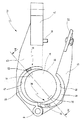
図1において、10は工作機械を示し、その作業スピンドルが11で部分断面方式により図示されている。作業スピンドル11は、軸12の周りに回転可能に載置されていて、これが矢印13で示されている。
In FIG. 1,
作業スピンドル11は、その下端で円錐形のツール受容部(レセプタクル)14を有し、その中に、例えばそのマガジン位置に15で示されるようなツールホルダが挿入され得る。
ツールホルダ15は、標準化された急斜テーパ16を有し、これは一般に公知のツールホルダ用の覆い(シース)17により飛散する切粉から保護されている。
急斜テーパ16の下において、ツールホルダ15は、厚みを帯びたカラー18を有していて、これは丸く包囲して外側に開放したグリッパ溝19を備えており、そこでツールホルダ15がグリッパ21により保持されている。ツールホルダ15において、厚みを帯びたカラー18はその底部でシャンク22に隣接していて、そこで作業ツール(図1及び2には示されていない)が保持される。
Under the steeply
グリッパ21は、ツール変更アーム23により保持されており、これはそれ自体公知の方式で、第1バー24及び第2バー25からなり、これらを通じてそれはスリーブ26に載置され、これは、ツールスピンドル11を包囲するスピンドルハウジング(図示せず)上で垂直方向に調整可能な方式で載置され、これは矢印27で示されている。2つのバー24及び25はスリーブ26に回転軸28を介して載置され、グリッパ21に接続されており、従来技術から公知の平行四辺形型ガイドが形成されるようになっている。
The
ツールホルダ用の覆い17は、バー24及び25に回転軸29を介して接続されている。バー25は、更なる回転軸31を介して、ピストン33とシリンダ34からなる作動ユニット32に接続されている。シリンダ34内でのピストン33の位置は、位置センサ35によって検出され、これは、終了位置センサとすることができ、ツール変更アーム23及びそれゆえツールホルダ15が、それらのマガジン位置、すなわち急斜テーパ16がツールホルダ用の覆い17のキャビティ36内に来る位置まで持ち上がる程度に、ピストン33がシリンダ34内に運搬されたか否かを示す。
The
バー24及び25における平行四辺形型ガイド及びツールホルダ用の覆いの関節配置は、公知の方式で、ピストン33が延ばされたときに、ツールホルダ15が、回転軸12と平行に配置されたその軸37内に留まり、ツール受容部14のもとで旋回され得ることを確実にするが、その目的のため、スリーブ26は下方に移動されなければならない。軸12及び37が互いに一列に並んでいるときに、スリーブ26は再び上方に移動され、ツールホルダ15がその作業位置(図2に示される)に持ち上がり、そこで急斜テーパ16がツール受容部14に着座し、そこで公知の方式でクランプされる。
The joint arrangement of the cover for the parallelogram guide and the tool holder in the
もっとも、軸37がマガジン位置内で傾斜されてツールが放射方向外側に向くような構造も考えられる。
However, a structure is also conceivable in which the
図1でも理解できるように、ツールホルダ15はそのマガジン位置内で、ツール受容部14から距離38だけ横方向にずれていて、マガジン位置はまたツール受容部14の上方に配置されている。
As can also be seen in FIG. 1, the
このような例えばDE4031997A1から公知の作業ツールの場合に、複数のツール変更アームが作業スピンドル11の周りのスリーブ26に配置され、グリッパ21は、プッシュプルモードでツールホルダ15をツール受容部14内へ各場合に搬送し、機械加工工程の間ツールホルダ15に留まっている。
In the case of such a work tool known from DE 4031997 A1, for example, a plurality of tool change arms are arranged on the
39で示される方向決め(オリエンテーション)手段が、ツールホルダ15とグリッパ21の間に設けられていて、ツールホルダをグリッパ21内にマガジン位置と作業位置の間のその移送の間非回転方式で保証し、ツールホルダ15を、それがツール受容部14にクランプされた後にのみ解放し、それがグリッパ21に関して作業スピンドル11の回転により回転され得るようになっている。
Orienting (orientation) means indicated by 39, provided between the
これからより詳細に説明される方式で、図2に示された位置から少量だけ下降されたスリーブ26により、方向決め手段39の解放が行われる。
In a manner that will now be described in more detail, the orientation means 39 is released by the
図2において、防止要素(ブロッキングエレメント)は、図1及び2の実施例ではラッチ要素41として構成され、40で示されている。これから説明される方式で、防止要素40は、ツールホルダ15が仮にグリッパ21に関して周辺にミスアラインされた場合に、そのマガジン位置に持ち上がるのを防止する。この目的のため、図1及び2に示す実施例のラッチ(ラッチング)要素41は、カラー18に設けられた凹所に係合する。もしツールホルダ15がグリッパ21に関して回転されると、ラッチ要素41はこの凹所に係合できず、これはツール変更アームが図1に示されるそのマガジン位置まで持ち上がる程十分遠くまでグリッパ21が上方に移動され得ないことを意味している。マガジン位置からのこの逸脱は、位置センサ35によって認識され、これはこのエラーを機械ツール10のシーケンス制御装置に知らせる。
In FIG. 2, the prevention element ( blocking element ) is configured as a
位置センサ35及び防止要素40は、それゆえグリッパ21上のツールホルダ15の周辺方向のアラインメントのための位置決め表示器を形成する。この位置決め表示器は、それゆえ、ツール受容部14から交換されたツールホルダ15が、グリッパ21の加速及びブレーキの間に回転され又は傾斜されるか否かを認識するだけではないが、これは例えばそれらが切粉又は冷媒により汚れてしまうため、方向決め手段39はこれを防止できない。また、グリッパ21にツールホルダ15が装備されているときに、装備目的で延ばされたツール変更アーム23がマガジン位置内に戻された場合に、起こりうる逸脱が直ぐに認識される。
The
方向決め手段は、図1及び2の中からグリッパ21の平面図を示す図3に関連付けてより詳細に説明される。
The direction determining means will be described in more detail in connection with FIG. 3 showing a plan view of the
グリッパ21は、アーム42を介してバー24及び25に接続されており、そこに第1ジョー43が着座しており、これは第2折込ジョー45に回転軸44を介して接続されている。2つのジョー43及び45は、半円開口47及び48をそれぞれ有しており、これらはツールホルダ15の外周(46で示す)に合わせられ、その中にウェブ49が突出し、これは放射方向内側に突出してグリッパ溝19(図3には示されていない)に、一般に公知のように係合する。
The
装備目的で、グリッパ21は図3に示された方式で開放され、その後ツールホルダが挿入され、ジョー45は、閉鎖の後、ピン51及びファスナ52を介してジョー43にロックされる。
For installation purposes, the
ツールホルダ15は、こうしてグリッパ21に係留状態で載置される。
The
直径方向に互いに反対側にある2つのラッチ突起53及び54は、ウェブ49上に配置されていて、かつ、図示された実施例においては、ウェブ49上にねじ込まれた2つの摺動ブロックとして構成されている。このねじの図示は明確さの理由で省略されているが、摺動ブロックは、結合性、すなわち、例えば接着又は半田付け、或いは摩擦又はぴったり合うように作られた例えばクランプされるマテリアルジョイントとすることも可能である。
Two
ラッチ突起53及び54には、ツールホルダ15上の方向決めノッチ55及び56が割り当てられていて、これらのノッチは図3の突起の面から下方に開口している。この方式で、ツールホルダ15は、いわばラッチ突起53、54に上から載置され、後者が方向決めノッチ55、56に係合し、ツールホルダ15を非回転方式でグリッパ21に保持する方式になっている。
Latching
図3内のツールホルダ15は、中空テーパシャンクツールホルダ(HSK)と言われていて、これは図4の側面に明らかにされているが、もっとも、方向決め手段は図1及び2に概略的に示されるように、HSKツールホルダに関連付けて以下に説明されるのと同様に、急斜テーパツールホルダ(SK)に作用する。
The
図4において理解できるように、方向決めノッチ55は、下方に開放する方式でカラー18に形成されている。さらに、図4はシャンク22に締め付けられるマシニングツール57を示している。
As can be seen in FIG. 4, the
ツールホルダ15は、中空のテーパシャンク58を有しており、その上方に向いた開口59で、クランプシステム62のドロワーインテーパ61が、図4の頂部で概略的に示されているように係合する。ツールホルダ15がツール受容部14に入るとき、ドロワーインテーパ61が中空テーパシャンク58に入り、拡張し、その過程で、ツールホルダ15をツール受容部14に更に引き込む。カラー18は、その環状表面63を作業スピンドル11の端面64に接触させる。環状表面63と端部表面64の間の平坦接触は、作業スピンドル11の軸12とツールホルダ15の軸37が一列に並ぶことを確実にする。
The
作業スピンドル11とツールホルダ15の間の周辺方向のアラインメントが2つの受け用(キャッチ)スロット65及び66によって制御されていて、受け用スロット65は受け用スロット66よりも更に下方に切り欠かれていて、これは図5の断面図で特に直ちに理解され得る。図5は、更にまた、小さい冷媒パイプ67を示しており、これはツールホルダ15の内側に配置されていて、作業スピンドル11内の冷却システムがツール57に接続されることを確実にしている。
方向決めノッチ55及び56は、図5の断面図に示されていて、グリッパ21とそのジョー43及び45は、ラッチ突起53及び54と共に、図3のV−V線に沿った断面形状で示されている。図5の右側において、グリッパ21はなおその上方位置にあり、ラッチ突起53は方向決めノッチ55に係合し、ツールホルダ15が回転され得ないようになっている。これは、ツールホルダ15がツール受容部14内に導入され、そこでクランプされる位置である。グリッパ21は、さらにスリーブ26の下降により下降され、これは図5の左側に示されており、そこではラッチ突起54が方向決めノッチ56から自由になっている。方向決めノッチ55、56は、位置決めノッチとして構成され、これらはマシニングツール57の切削位置の周辺に割り当てられている。
Orienting
マガジン位置と作業位置の間の搬送の間に、ツールホルダ15の自重が、それをグリッパ溝19内に突出したウェブ49に休止させ、ラッチ突起53及び54が方向決めノッチ55及び56と係合状態にあり、ツールホルダ15がグリッパ21に関して回転され得ないようになっている。ツールホルダ15がツール受容部14内にクランプされた後、グリッパ21が下降され、これは図5の矢印68で示されている。これは、既述のように、スリーブ26を下降させることにより又はツール変更アーム23の更なる延長により、行われ得る。方向決め手段は、こうして、グリッパ21に関連する回転のため、ツールホルダ15を解放する。
During the transfer between the magazine position and the working position, the weight of the
ツール57の挿入終了後、作業スピンドル11はブレーキをかけられて停止し、グリッパ21はその後上昇される。この工程で、ツールホルダ15はその周辺地点に関して、ラッチ突起53及び54が方向決めノッチ55及び56と係合する方式でアラインされる。スリーブ26が今や下降され、ツールホルダ15がツール受容部14から自由となるようになっている。ツール変更アームはその後マガジン位置内で旋回され、これが図1に示されており、もう1つのツール変更アームが、ツールホルダにより支持された新しいほうのツールを作業スピンドル11内にクランプする目的で、延長される。
After the insertion of the
このツール変更は、高加速度で行われ、僅かだけでも、ツールホルダ15が方向決め手段から外れる、すなわち周辺で傾斜され回転される危険があるようになっている。これは、特に切粉及び冷媒が方向決めノッチ55及び56内に又はラッチ突起53及び54上に蓄積された場合に起こる。
This tool change takes place at a high acceleration, so that there is a risk that the
もし仮にこの起こり得るミスアラインメントが認識されなければ、ツールホルダ15は、次に挿入されるとき、作業スピンドル11内に位置的に正確な方式で挿入されず、それゆえそれはどうしても適所にクランプされ得ず、この場合、更に、クランプシステムへの損傷が排除され得ない。
If this possible misalignment is not recognized, the
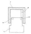
これを防止する目的で、既に図1及び2を参照して論じられた位置決め表示器が設けられる。図1及び2のラッチ要素41がツールホルダ用の覆い17から下方に突出する一方で、図6において断面図で概略的に示されたツールホルダ用の覆い17の場合、それはツールホルダ用の覆い17の内側にラッチ要素69として配置される。ラッチ要素69は、形状要素としてツールホルダ用の覆い17と一体的に形成される。
In order to prevent this, the positioning indicator already discussed with reference to FIGS. 1 and 2 is provided. While latching
図6は、受け用スロット65及び66を備えたHSKツールホルダ15を、更に概念的に示す。受け用スロット65は、受け用スロット66よりも深く構成されていて、ラッチ要素69がより深い受け用スロット65に係合した場合にのみ、ツールホルダ15がチューブ状ケース17内でそのマガジン位置に持ち上がることができるようになっている。ツールホルダ15がグリッパ21内で回転されるとき、ラッチ要素69はツールホルダ15の前側に突き当たるか、或いはそれは十分でない深さの第2の受け用スロット66内に180°回転して入る。いずれの場合もツールホルダ15はそのマガジン位置に到達することはなく、これは、他方で、図1の中のツール変更アーム23がそのマガジン位置に持ち上がり得ないことを意味し、これはその結果位置センサ35によって認識される。
FIG. 6 shows more conceptually the
位置センサ35とラッチ要素41又は69により形成される位置決め表示器は、それゆえ、オペレータによってグリッパ21内に不適切に設置されたツールホルダ15を識別する役割を果たすだけでなく、新規な工作機械10の操作の間、ミスアラインされたツールホルダ15が、適所にクランプされ得ず、そして恐らくクランプシステムが確実に損傷を受けるところで、ツール受容部14内に導入されることも防止する。
The positioning indicator formed by the
本発明は、HSKツールホルダに関連して、図4から6で説明されたが、それはまたSKツールホルダ又は他のツールホルダにも適用可能である。図7は、SKホルダ以外の図5及び6の結合図を示す。図7において、図4から6と同一の構成には同一の符号が使用されている。 Although the present invention has been described in FIGS. 4 to 6 in connection with an HSK tool holder, it is also applicable to SK tool holders or other tool holders. FIG. 7 shows the combined view of FIGS. 5 and 6 other than the SK holder. In FIG. 7, the same reference numerals are used for the same components as in FIGS.
HSK及びSKツールホルダ15の間の重要な差異は、図5に示された受け用スロット15及び66がSKツールホルダのカラー18のところに配置されていることである。もっとも、図7において、より明瞭にするためそれらは描かれていない。図4から6に示されたHSKツールホルダ15と図7に示されたSKツールホルダ15の間の更なる差異は、図3に示された方向決めノッチ55及び56について、唯一の方向決めノッチが設けられ、グリッパ21のところで唯一のラッチ突起53、すなわち1つの摺動ブロックが設けられるようになっていることである。ツールホルダ15がグリッパ21内に正確な方向決めで挿入されなかったので、方向決めノッチ55は、図7で見ることはできない。
An important difference between HSK and
グリッパ21内でのツールホルダ15の回転配置は、ツールホルダ15の長手軸37がツールホルダ用の覆い17の長手軸71と並ばず、図7の後者に関して左に傾斜されることにつながる。
The rotational arrangement of the
HSKツールホルダとSKツールホルダの間の更なる差異は、内部でクランプシステム62のドロワーインテーパ61が係合する中空テーパシャンク58として急斜テーパ16が具体化されていないが、締め付けボルト72が急斜テーパ16の上端内に捩じ込まれていて、図4のクランプシステム62が締め付けボルト72のヘッド73を判断するが、それはヘッド73を拡張せず、グリップすることである。
A further difference between the HSK tool holder and the SK tool holder is that the
ツールホルダ用の覆い17の上部において、防止要素40として機能する凹所74が設けられていて、長手軸37及び71が互いに並んだ場合、すなわち、ツールホルダ15がグリッパ21内に正確な方向決めで挿入された場合に、その凹所74の中に締め付けボルト72のヘッド73が係合する。この角度方向決めのみにおいて、ツールホルダ15は完全にツールホルダ用の覆い17内に完全に受容され、これは度々述べられた位置センサ35によって認識される。
In the upper part of the
図7に示されるように、ツールホルダ15がグリッパ21に関して回転されると、ヘッド73は離れて傾斜されるため、それは凹所74内に係合できず、前面75に付き当たる。それゆえ、ツールホルダ15はツールホルダ用の覆い17内に完全に到達できず、これもまた既述の位置センサ35により検知される。
As shown in FIG. 7, when the
もちろん、HSKツールホルダが図7のSKツールホルダと同様なミスアラインメントの場合に傾斜するような唯一の方向決めノッチ55をそれに設けることも可能である。この場合、図6のツールホルダ用の覆い17に、図7の凹所74に対応する凹所が設けられ、ツールホルダ用の覆い17とツールホルダ15の長手軸が一致するときに、その凹所の中に図4のHSKツールホルダの中空テーパシャフト58が係合可能である。
Of course, it is also possible to provide it with a
図7の実施例で、ボルト72のヘッド73は、こうして凹所74内に係合する突起として作用する。ツールホルダ15のもう1つのサイトにおいて、ツールホルダ用の覆い17のところで各凹所と共に作用する突起を設けることはもちろん可能である。
In the embodiment of FIG. 7, the
この程度まで説明された工作機械の場合、ツールホルダ15とグリッパ21の間に設けられた方向決め手段は、それゆえ、ツールホルダ15が正確な周辺方向のアラインメントで静止した作業スピンドル11内に導入されることができ、そこで直ぐにクランプされ得ることを確実にする。グリッパ21の下降は、方向決め手段が解放されることにつながり、作業スピンドルが操作スピードまで到達され得るようになっている。
When the machine tool described to this extent, orienting means provided between the
位置センサ35及びラッチ要素41又は69から形成される位置決め表示器は、ツールホルダ15の周辺方向のアラインメントをそのマガジン位置でモニターし、操作の間のグリッパ21の不適切な取付けとツールホルダ15の回転又は傾斜の両方が認識され得るようになっている。この場合、位置決め表示器に位置センサ35を割り当てることは絶対に必要というわけではない。別体の位置センサをツールホルダ用の覆いにフィットすることも可能であり、もし適当であれば、ラッチ要素41及び69を省略しても良いようになっている。
A positioning indicator formed from the
10 工作機械
11 作業スピンドル
12 軸
14 ツール受容部
15 ツールホルダ
16 急斜テーパ
18 カラー
19 グリッパ溝
21 グリッパ
23 ツール変更アーム
24 第1バー
25 第2バー
26 スリーブ
33 ピストン
34 シリンダ
35 位置センサ
40 防止要素
41 ラッチ要素
49 ウェブ
53、54 ラッチ突起
55、56 方向決めノッチ
61 ドロワーインテーパ
62 クランプシステム
65、66 受け用スロット
69 ラッチ要素
72 締め付けボルト
73 ヘッド
DESCRIPTION OF
Claims (14)
位置決め表示器(35、40)がツールホルダ(15)の周辺方向のアラインメントのために設けられ、この位置決め表示器がツールホルダ(15)とグリッパ(21)の間のミスアラインメントを表示し、
位置決め表示器(35、40)に、防止要素(40)が割り当てられていて、これが、ツールホルダ(15)がグリッパ(21)に関してミスアラインメントの状態になったときにツールホルダ(15)がそのマガジン位置に持ち上がることを防止することを特徴とする工作機械。 The magazine position having at least one working spindle (11), the tool spindle (14) for the tool holder (15) being provided and spaced from the tool receiving part (14); At least one tool changing arm with a gripper (21) for the purpose of transporting the tool holder (15) between its working positions where the tool holder (15) can be clamped in the tool receiver (14) (23), in which a tool holder (15) is held in a circumferentially aligned state with respect to the gripper (21).
A positioning indicator (35, 40) is provided for peripheral alignment of the tool holder (15), the positioning indicator displaying a misalignment between the tool holder (15) and the gripper (21),
The positioning indicator (35, 40) is assigned a prevention element (40), which when the tool holder (15) is misaligned with respect to the gripper (21) Machine tool characterized by preventing lifting to the magazine position.
Applications Claiming Priority (1)
| Application Number | Priority Date | Filing Date | Title |
|---|---|---|---|
| DE10323593A DE10323593A1 (en) | 2003-05-16 | 2003-05-16 | machine tool |
Publications (2)
| Publication Number | Publication Date |
|---|---|
| JP2004338086A JP2004338086A (en) | 2004-12-02 |
| JP4062539B2 true JP4062539B2 (en) | 2008-03-19 |
Family
ID=33016451
Family Applications (1)
| Application Number | Title | Priority Date | Filing Date |
|---|---|---|---|
| JP2004144683A Expired - Fee Related JP4062539B2 (en) | 2003-05-16 | 2004-05-14 | Machine Tools |
Country Status (5)
| Country | Link |
|---|---|
| US (1) | US7115082B2 (en) |
| EP (1) | EP1477270B1 (en) |
| JP (1) | JP4062539B2 (en) |
| DE (2) | DE10323593A1 (en) |
| ES (1) | ES2268536T3 (en) |
Families Citing this family (8)
| Publication number | Priority date | Publication date | Assignee | Title |
|---|---|---|---|---|
| DE10323592B4 (en) * | 2003-05-16 | 2006-03-23 | Chiron-Werke Gmbh & Co Kg | machine tool |
| DE102007050858A1 (en) * | 2007-10-24 | 2009-04-30 | Weber Maschinenbau Gmbh Breidenbach | Device for slicing a food product |
| US7690874B2 (en) * | 2007-12-12 | 2010-04-06 | Kennametal Inc. | Rotary tapered tool holder with adapter sleeve |
| KR101405376B1 (en) * | 2008-04-18 | 2014-06-10 | 현대자동차 주식회사 | Machining center with automatic tool feed |
| CN102196884B (en) * | 2008-09-30 | 2013-12-18 | 应用材料公司 | Self-Aligning Facility Auto-Couplers |
| CN103186808B (en) * | 2011-12-29 | 2016-03-09 | 鸿富锦精密工业(深圳)有限公司 | Label base |
| TWI749882B (en) * | 2020-11-19 | 2021-12-11 | 臻賞工業股份有限公司 | Tool clamp with safe engagement function |
| JP7055928B1 (en) * | 2021-09-21 | 2022-04-18 | Dmg森精機株式会社 | Machine tools, control methods, and control programs |
Family Cites Families (29)
| Publication number | Priority date | Publication date | Assignee | Title |
|---|---|---|---|---|
| US3516149A (en) * | 1968-02-05 | 1970-06-23 | Ex Cell O Corp | Machining apparatus with automatic tool changing means |
| SE347885B (en) * | 1970-08-20 | 1972-08-21 | Pullmax Ab | |
| US3999664A (en) * | 1974-06-26 | 1976-12-28 | Houdaille Industries, Inc. | Tool changer with dual axis of rotation |
| US3953039A (en) * | 1974-08-30 | 1976-04-27 | Textron Inc. | Toolholder for machine tools |
| US3975817A (en) * | 1974-10-09 | 1976-08-24 | Houdaille Industries, Inc. | Fluid-actuated tool changer with dual axis of rotation |
| US4141133A (en) * | 1975-09-02 | 1979-02-27 | The Bullard Company | Tool changer for vertical boring machine |
| US3964616A (en) * | 1975-09-29 | 1976-06-22 | Cincinnati Milacron, Inc. | Machine tool interchange arm |
| JPS5292175A (en) * | 1976-01-29 | 1977-08-03 | Toyoda Mach Works Ltd | Machine tool which is provided with automatic tool changing device |
| US4196506A (en) * | 1976-09-07 | 1980-04-08 | Giddings & Lewis, Inc. | Tool changer machining center |
| US4321746A (en) * | 1978-11-01 | 1982-03-30 | White Consolidated Industries, Inc. | Tool changer for vertical boring machine |
| US4356621A (en) * | 1980-07-25 | 1982-11-02 | Toyoda Koki Kabushiki Kaisha | Machine tool with automatic tool change |
| US4399603A (en) * | 1980-11-17 | 1983-08-23 | Giddings & Lewis, Inc. | Power grip tool exchange arm for machining center |
| JPS5789542A (en) * | 1980-11-21 | 1982-06-03 | Toyoda Mach Works Ltd | Automatic tool replacing apparatus |
| DE3376473D1 (en) | 1982-09-13 | 1988-06-09 | Chiron Werke Gmbh | Machine tool with tool magazine |
| DE3320851A1 (en) * | 1983-06-09 | 1984-12-13 | Chiron-Werke Gmbh, 7200 Tuttlingen | Machine tool |
| CH661237A5 (en) * | 1984-12-19 | 1987-07-15 | Arcofil Sa | METHOD FOR AUTOMATICALLY LOADING WORKSTATIONS AND DEVICE FOR CARRYING OUT SAID METHOD. |
| US4615101A (en) * | 1985-03-08 | 1986-10-07 | Intelledex Incorporated | Tool interface for robot end effectors |
| DE3620364C1 (en) | 1986-06-18 | 1988-01-21 | Chiron Werke Gmbh | Gripper for a tool holder of a machine tool |
| AU1834188A (en) | 1987-06-29 | 1989-01-05 | Kendall Company, The | Novel medicated dressings |
| DE3827053A1 (en) | 1988-08-10 | 1990-02-15 | Chiron Werke Gmbh | MACHINE TOOL |
| DE4031997A1 (en) | 1990-10-09 | 1992-04-16 | Chiron Werke Gmbh | MACHINE TOOL |
| US5044063A (en) * | 1990-11-02 | 1991-09-03 | The United States Of America As Represented By The Administrator Of The National Aeronautics And Space Administration | Robotic tool change mechanism |
| DE4415306A1 (en) * | 1994-04-30 | 1995-11-02 | Chiron Werke Gmbh | Machine tool |
| ES2145350T3 (en) | 1995-09-02 | 2000-07-01 | Chiron Werke Gmbh | MACHINE TOOL. |
| US5879277A (en) * | 1997-06-11 | 1999-03-09 | Kawasaki Robotics (Usa) Inc. | Tool storage and retrieval system |
| US5954623A (en) * | 1997-10-07 | 1999-09-21 | Davis; Steven E. | Tool changer apparatus and method of automating a machine tool |
| JP2000354989A (en) * | 1999-06-16 | 2000-12-26 | Fanuc Ltd | Automatic blade changing device |
| US6641511B2 (en) * | 2000-08-31 | 2003-11-04 | Hurco Companies, Inc. | Movable arm activated tool changer for machine tool system |
| US7037248B2 (en) * | 2000-10-27 | 2006-05-02 | Tokyo Seimitsu Co., Ltd. | Machine tool |
-
2003
- 2003-05-16 DE DE10323593A patent/DE10323593A1/en not_active Ceased
-
2004
- 2004-05-12 DE DE502004000939T patent/DE502004000939D1/en not_active Expired - Lifetime
- 2004-05-12 ES ES04011239T patent/ES2268536T3/en not_active Expired - Lifetime
- 2004-05-12 EP EP04011239A patent/EP1477270B1/en not_active Expired - Lifetime
- 2004-05-14 JP JP2004144683A patent/JP4062539B2/en not_active Expired - Fee Related
- 2004-05-14 US US10/846,492 patent/US7115082B2/en not_active Expired - Fee Related
Also Published As
| Publication number | Publication date |
|---|---|
| ES2268536T3 (en) | 2007-03-16 |
| EP1477270A3 (en) | 2005-01-12 |
| US20050014617A1 (en) | 2005-01-20 |
| DE10323593A1 (en) | 2004-12-09 |
| EP1477270B1 (en) | 2006-07-12 |
| EP1477270A2 (en) | 2004-11-17 |
| JP2004338086A (en) | 2004-12-02 |
| DE502004000939D1 (en) | 2006-08-24 |
| US7115082B2 (en) | 2006-10-03 |
Similar Documents
| Publication | Publication Date | Title |
|---|---|---|
| US4234277A (en) | Motor quick-change chuck system for tool having cylindrically shaped adapter portion | |
| US4184692A (en) | Motor quick-change chuck system for tool having cylindrically shaped adapter portion | |
| JP4062539B2 (en) | Machine Tools | |
| US4188041A (en) | Motor quick-change chuck system for tool having cylindrically shaped adapter portion | |
| EP2505285B1 (en) | Machine tool and tool holder | |
| CA1216179A (en) | Drill chuck for hand-held drilling device | |
| KR100724221B1 (en) | clamping device for a hollow shaft | |
| JP6669693B2 (en) | Handling equipment used in machine tools | |
| US8721397B2 (en) | Device for machining, in particular eroding and grinding, rotational work-pieces provided with cutting edges | |
| KR20100113113A (en) | Coupling mechanism and method for automatically coupling tool holders to tool fixtures on operating devices | |
| JP4062540B2 (en) | Machine Tools | |
| US10576562B1 (en) | Circular saw cutting machine | |
| US4273344A (en) | Motor quick-change chuck system for tool having cylindrically shaped adapter portion | |
| US4700442A (en) | Tool changing apparatus for a machine tool | |
| JP4156209B2 (en) | Compound processing equipment | |
| US5772566A (en) | Machine tool | |
| CN112566743B (en) | Method for confirming gripping accuracy of chuck, method for replacing jaws of chuck, and device for confirming gripping accuracy of chuck | |
| ES2257580T3 (en) | TOOL CHANGER FOR A MACHINE-TOOL. | |
| US4812091A (en) | Exchange system on an irremovable machining center | |
| JP2003181747A (en) | Main spindle of machine tool having device for detecting mounting condition of tool | |
| JPS632641A (en) | Gripper for tool holder of machine tool | |
| US4109360A (en) | Machine with processing heads | |
| US4190938A (en) | Machine with processing heads | |
| KR101405376B1 (en) | Machining center with automatic tool feed | |
| US6953198B2 (en) | Short pull-back chuck |
Legal Events
| Date | Code | Title | Description |
|---|---|---|---|
| A131 | Notification of reasons for refusal |
Free format text: JAPANESE INTERMEDIATE CODE: A131 Effective date: 20061212 |
|
| A601 | Written request for extension of time |
Free format text: JAPANESE INTERMEDIATE CODE: A601 Effective date: 20070301 |
|
| A602 | Written permission of extension of time |
Free format text: JAPANESE INTERMEDIATE CODE: A602 Effective date: 20070307 |
|
| A521 | Written amendment |
Free format text: JAPANESE INTERMEDIATE CODE: A523 Effective date: 20070611 |
|
| A131 | Notification of reasons for refusal |
Free format text: JAPANESE INTERMEDIATE CODE: A132 Effective date: 20070724 |
|
| A521 | Written amendment |
Free format text: JAPANESE INTERMEDIATE CODE: A523 Effective date: 20070726 |
|
| A131 | Notification of reasons for refusal |
Free format text: JAPANESE INTERMEDIATE CODE: A131 Effective date: 20070828 |
|
| A601 | Written request for extension of time |
Free format text: JAPANESE INTERMEDIATE CODE: A601 Effective date: 20071026 |
|
| A602 | Written permission of extension of time |
Free format text: JAPANESE INTERMEDIATE CODE: A602 Effective date: 20071031 |
|
| A521 | Written amendment |
Free format text: JAPANESE INTERMEDIATE CODE: A523 Effective date: 20071114 |
|
| TRDD | Decision of grant or rejection written | ||
| A01 | Written decision to grant a patent or to grant a registration (utility model) |
Free format text: JAPANESE INTERMEDIATE CODE: A01 Effective date: 20071218 |
|
| A61 | First payment of annual fees (during grant procedure) |
Free format text: JAPANESE INTERMEDIATE CODE: A61 Effective date: 20071219 |
|
| R150 | Certificate of patent or registration of utility model |
Free format text: JAPANESE INTERMEDIATE CODE: R150 Ref document number: 4062539 Country of ref document: JP Free format text: JAPANESE INTERMEDIATE CODE: R150 |
|
| FPAY | Renewal fee payment (event date is renewal date of database) |
Free format text: PAYMENT UNTIL: 20110111 Year of fee payment: 3 |
|
| FPAY | Renewal fee payment (event date is renewal date of database) |
Free format text: PAYMENT UNTIL: 20110111 Year of fee payment: 3 |
|
| FPAY | Renewal fee payment (event date is renewal date of database) |
Free format text: PAYMENT UNTIL: 20120111 Year of fee payment: 4 |
|
| R250 | Receipt of annual fees |
Free format text: JAPANESE INTERMEDIATE CODE: R250 |
|
| FPAY | Renewal fee payment (event date is renewal date of database) |
Free format text: PAYMENT UNTIL: 20130111 Year of fee payment: 5 |
|
| R250 | Receipt of annual fees |
Free format text: JAPANESE INTERMEDIATE CODE: R250 |
|
| R250 | Receipt of annual fees |
Free format text: JAPANESE INTERMEDIATE CODE: R250 |
|
| R250 | Receipt of annual fees |
Free format text: JAPANESE INTERMEDIATE CODE: R250 |
|
| R250 | Receipt of annual fees |
Free format text: JAPANESE INTERMEDIATE CODE: R250 |
|
| R250 | Receipt of annual fees |
Free format text: JAPANESE INTERMEDIATE CODE: R250 |
|
| R250 | Receipt of annual fees |
Free format text: JAPANESE INTERMEDIATE CODE: R250 |
|
| R250 | Receipt of annual fees |
Free format text: JAPANESE INTERMEDIATE CODE: R250 |
|
| R250 | Receipt of annual fees |
Free format text: JAPANESE INTERMEDIATE CODE: R250 |
|
| RD02 | Notification of acceptance of power of attorney |
Free format text: JAPANESE INTERMEDIATE CODE: R3D02 |
|
| LAPS | Cancellation because of no payment of annual fees |