JP4057061B2 - Method and apparatus for providing centralized power control management for a series of base stations - Google Patents
Method and apparatus for providing centralized power control management for a series of base stations Download PDFInfo
- Publication number
- JP4057061B2 JP4057061B2 JP53283197A JP53283197A JP4057061B2 JP 4057061 B2 JP4057061 B2 JP 4057061B2 JP 53283197 A JP53283197 A JP 53283197A JP 53283197 A JP53283197 A JP 53283197A JP 4057061 B2 JP4057061 B2 JP 4057061B2
- Authority
- JP
- Japan
- Prior art keywords
- base station
- remote unit
- data
- forward link
- link frame
- Prior art date
- Legal status (The legal status is an assumption and is not a legal conclusion. Google has not performed a legal analysis and makes no representation as to the accuracy of the status listed.)
- Expired - Fee Related
Links
- 238000000034 method Methods 0.000 title claims description 78
- 238000004891 communication Methods 0.000 claims description 94
- 230000002441 reversible effect Effects 0.000 claims description 70
- 238000011156 evaluation Methods 0.000 claims description 13
- 238000005259 measurement Methods 0.000 claims description 8
- 238000012217 deletion Methods 0.000 claims description 4
- 230000037430 deletion Effects 0.000 claims description 4
- 230000008569 process Effects 0.000 description 40
- 230000001413 cellular effect Effects 0.000 description 37
- 230000005540 biological transmission Effects 0.000 description 35
- 238000012545 processing Methods 0.000 description 21
- 230000006870 function Effects 0.000 description 20
- 230000008901 benefit Effects 0.000 description 15
- 238000004364 calculation method Methods 0.000 description 13
- 230000007423 decrease Effects 0.000 description 12
- 230000029058 respiratory gaseous exchange Effects 0.000 description 9
- 230000008859 change Effects 0.000 description 8
- 238000005562 fading Methods 0.000 description 7
- 238000007726 management method Methods 0.000 description 6
- 238000001228 spectrum Methods 0.000 description 6
- 230000007246 mechanism Effects 0.000 description 5
- 235000009508 confectionery Nutrition 0.000 description 4
- 238000010586 diagram Methods 0.000 description 4
- 230000010267 cellular communication Effects 0.000 description 3
- 230000003247 decreasing effect Effects 0.000 description 3
- 230000000694 effects Effects 0.000 description 3
- 230000002411 adverse Effects 0.000 description 2
- 230000015556 catabolic process Effects 0.000 description 2
- 238000006731 degradation reaction Methods 0.000 description 2
- VJYFKVYYMZPMAB-UHFFFAOYSA-N ethoprophos Chemical compound CCCSP(=O)(OCC)SCCC VJYFKVYYMZPMAB-UHFFFAOYSA-N 0.000 description 2
- 238000012986 modification Methods 0.000 description 2
- 230000004048 modification Effects 0.000 description 2
- 230000010363 phase shift Effects 0.000 description 2
- 230000004044 response Effects 0.000 description 2
- 230000003595 spectral effect Effects 0.000 description 2
- 239000013598 vector Substances 0.000 description 2
- 101000652224 Homo sapiens Suppressor of cytokine signaling 5 Proteins 0.000 description 1
- 102100030523 Suppressor of cytokine signaling 5 Human genes 0.000 description 1
- 230000002159 abnormal effect Effects 0.000 description 1
- 230000002776 aggregation Effects 0.000 description 1
- 238000004220 aggregation Methods 0.000 description 1
- 238000013459 approach Methods 0.000 description 1
- 230000001680 brushing effect Effects 0.000 description 1
- 125000004122 cyclic group Chemical group 0.000 description 1
- 238000011157 data evaluation Methods 0.000 description 1
- 230000007812 deficiency Effects 0.000 description 1
- 230000001934 delay Effects 0.000 description 1
- 238000013461 design Methods 0.000 description 1
- 238000001514 detection method Methods 0.000 description 1
- 230000006866 deterioration Effects 0.000 description 1
- 238000005516 engineering process Methods 0.000 description 1
- 230000006872 improvement Effects 0.000 description 1
- 230000003993 interaction Effects 0.000 description 1
- 230000000737 periodic effect Effects 0.000 description 1
- 230000009467 reduction Effects 0.000 description 1
- 238000010187 selection method Methods 0.000 description 1
- 238000012163 sequencing technique Methods 0.000 description 1
- 230000011664 signaling Effects 0.000 description 1
- 230000007480 spreading Effects 0.000 description 1
- 230000002123 temporal effect Effects 0.000 description 1
- 238000012546 transfer Methods 0.000 description 1
Images


Classifications
-
- H—ELECTRICITY
- H04—ELECTRIC COMMUNICATION TECHNIQUE
- H04W—WIRELESS COMMUNICATION NETWORKS
- H04W52/00—Power management, e.g. TPC [Transmission Power Control], power saving or power classes
- H04W52/04—TPC
- H04W52/06—TPC algorithms
- H04W52/14—Separate analysis of uplink or downlink
- H04W52/143—Downlink power control
-
- H—ELECTRICITY
- H04—ELECTRIC COMMUNICATION TECHNIQUE
- H04W—WIRELESS COMMUNICATION NETWORKS
- H04W52/00—Power management, e.g. TPC [Transmission Power Control], power saving or power classes
- H04W52/04—TPC
- H04W52/06—TPC algorithms
- H04W52/14—Separate analysis of uplink or downlink
- H04W52/146—Uplink power control
-
- H—ELECTRICITY
- H04—ELECTRIC COMMUNICATION TECHNIQUE
- H04W—WIRELESS COMMUNICATION NETWORKS
- H04W52/00—Power management, e.g. TPC [Transmission Power Control], power saving or power classes
- H04W52/04—TPC
- H04W52/38—TPC being performed in particular situations
- H04W52/40—TPC being performed in particular situations during macro-diversity or soft handoff
-
- H—ELECTRICITY
- H04—ELECTRIC COMMUNICATION TECHNIQUE
- H04W—WIRELESS COMMUNICATION NETWORKS
- H04W36/00—Hand-off or reselection arrangements
- H04W36/16—Performing reselection for specific purposes
- H04W36/18—Performing reselection for specific purposes for allowing seamless reselection, e.g. soft reselection
-
- H—ELECTRICITY
- H04—ELECTRIC COMMUNICATION TECHNIQUE
- H04W—WIRELESS COMMUNICATION NETWORKS
- H04W52/00—Power management, e.g. TPC [Transmission Power Control], power saving or power classes
- H04W52/04—TPC
- H04W52/06—TPC algorithms
- H04W52/16—Deriving transmission power values from another channel
Description
[発明の背景]
I.発明の技術分野
本発明は、通信システム、より詳細には、通常の基地局の2つのセクタ間におけるハンドオフを実行するための方法及び装置に関する。
II.関連する技術の説明
CDMA(Code Division Multiple Access)(符号分割多重接続)セルラー電話、無線ローカル・ループ又はパーソナル通信システムにおいては、システムの中のすべての基地局との通信に共通の周波数帯域を使用している。共通の周波数帯域を使用することにより、リモート・ユニットと複数の基地局の間での同時通信が可能となる。この共通の周波数帯域に割り当てられる信号は、高速の擬似ノイズ(pseudonoise)(PN)コードを使用するスプレッド・スペクトラムCDMA波形の特性によって受信局において識別される。高速のPNコードは、基地局とリモート・ユニット(remote unit)の双方から送信される信号を変調するために使用される。異なるPNコード又は時間的なオフセットを持ったPNコードを使用する送信局では、受信局において分離して受信することのできる信号を生成する。高速のPN変調によれば、受信局において、無線チャンネルのマルチパス特性又は意図的に導入されたダイバーシティのために信号がいくつかの別個の伝播経路を通過した場合に、1つの送信局から送信された信号と同一の信号について複数の受信結果を得ることができる。
無線チャンネルのマルチパス特性により、送信局と受信局の間においていくつかの別個の伝播経路を経由したマルチパス信号が生成される。マルチパス・チャンネルの特性の1つとして、チャンネルを経由した信号に時間軸上での拡散が生じる。例えば、理想的なインパルスがマルチパルス・チャンネルを経由して伝送されると、受信信号は連続したパルス列として観測される。マルチパスのもう1つの特性としては、チャンネル内の各経路ごとに異なった減衰特性を与えることがある。例えば、理想的なインパルスがマルチパスのチャンネルを経由して伝送されると、受信パルス列の各パルスは、一般的に他の受信パルスと異なった信号の強度を持っている。マルチパス・チャンネルのもう1つの特性として、チャンネル内の各経路によって信号に位相差を生じさせることがある。例えば、理想的なインパルスがマルチパス・チャンネルを経由して伝送されると、受信されたパルス列の各パルスは、一般的に、他の受信パルスと異なった位相を持つ。
無線チャンネルでは、マルチパスは、その環境の中に含まれる建造物、樹木、自動車、人物などの障害物からの信号の反射によって生成される。一般的に、無線チャンネルは、マルチパスを生成する構造物の相対的な移動によって時間とともに変化するようなマルチパス・チャンネルである。例えば、理想的なインパルスがこのように時間とともに変化するマルチパスを経由して伝送されると、受信されるパルス列は、時刻、減衰特性、それにその理想的なインパルスが伝送された時刻の関数としてのフェーズによって変化を受けることになる。
チャンネルのマルチパスの特性は、信号のフェーディング(fading)を生じさせることがある。フェーディングは、マルチパス・チャンネルの位相特性によって生じるものである。フェードは、マルチパスのベクタ(vector)が打ち消し合う方向で加算されることにより、受信信号が各ベクトルのどれよりも小さくなった場合に発生する。例えば、正弦波が、減衰係数XdB、遅延時間δ、位相シフトθラジアンの第1の経路と、減衰係数XdB、遅延時間δ、位相シフト(θ+π)ラジアンの第2の経路の2つの経路を有するマルチチャンネルを経由して伝送された場合には、チャンネルの出力側においては信号は受信されない。
従来の無線電話システムにおいて採用されたアナログFM変調のような狭帯域変調システムにおいては、無線チャンネルに複数の経路が存在することにより、著しいマルチパス・フェーディングを生じていた。しかしながら広帯域のCDMAでは、前述したように、異なる経路は、受信局における復調のプロセスの中で識別することができる。このようにしてマルチパス信号を識別することにより、マルチパス・フェーディングの影響を大幅に削減することができるのみならず、CDMAシステムに利点をもたらすことができる。
基本的なCDMAシステムでは、各基地局は他の基地局のパイロット信号の符号フェーズとの間にオフセットを有する共通のPN拡散符号(PN spreading code)を持ったパイロット信号を送信する。システムの動作中には、リモート・ユニットは、通信を行っている基地局に隣接する基地局ごとの符号フェーズ・オフセットのリストを受け取る。リモート・ユニットは、隣接する基地局を含む一群の基地局からのパイロット信号の強度を探知するための検索エレメントを備えている。
ハンドオフ・プロセスの中で1つのリモート・ユニットと複数の基地局との間で通信をするための方法とシステムについては、本発明の譲受人に譲渡された1993年11月30日発行の米国特許No.5,267,261、"MOBILE ASSISTED SOFT HANDOFF IN A CDMA CELLULAR TELEPHONE SYSTEM"に開示されている。このシステムを使用することにより、元の基地局から次の基地局へのハンドオフが発生した場合でも、リモート・ユニットとエンド・ユーザの間における通信が妨げられることはない。この種類のハンドオフは、元の基地局との通信が終了する前に次の基地局との通信が確立されることから、ソフトなハンドオフであるということができる。リモート・ユニットが2つの基地局と通信しているときには、リモート・ユニットは、各基地局から受信した信号を、1つの基地局からのマルチパス信号を組み合わせるのと同じ要領で組み合わせる。
典型的なマクロセルラー(macrocellular)システムでは、システム・コントローラを設けて各基地局によって受信された信号の中から他のエンドユーザへの信号を生成させることができる。各基地局では、同じリモート・ユニットから受信された信号を、デコードする前に組み合わせることができる。これにより、複数信号の受信による利点を最大限に利用することができる。各基地局でのデコード結果は、システム・コントローラに供給される。信号は、一旦デコードされると、他の信号と‘組み合わせる’ことができない。このため、システム・コントローラは、1つのリモート・ユニットとの間で通信が確立された各基地局により生成された複数のデコード信号の中から任意の信号を選択しうるものでなければならない。複数の基地局の中から最も状態の良いデコード信号が選択され、他の信号は破棄される。
リモート・ユニットによって実現されるソフト・ハンドオフは、リモート・ユニットによって計測される何組かの基地局のパイロット信号の強度に基づいて行われる。アクティブ・セット(Active Set)は、アクティブ(active)な通信が確立される基地局の組み合わせである。ネイバー・セット(Neighbor Set)は、アクティブな基地局の周囲の基地局の組み合わせであり、通信を確立するために十分な信号強度を持っている可能性が高いものにより構成される。キャンディデイト・セット(Candidate Set)は、通信を確立するために十分な信号レベルにあるパイロット信号強度を持っている基地局の組み合わせである。
通信が初めて確立されると、リモート・ユニットは最初の基地局を通じて通信を行い、この時アクティブ・セットはその最初の基地局のみを含む。リモート・ユニットは、アクティブ・セット、キャンディデイト・セット、ネイバー・セットの基地局のパイロット信号の強度を監視する。ネイバー・セットに含まれている基地局のパイロット信号が予め定められたしきい値レベルを超えると、その基地局は、リモート・ユニットにおいてキャンディデイト・セットに加えられるとともに、ネイバー・セットから削除される。リモート・ユニットは、新しい基地局を特定するメッセージを最初の基地局に送出する。セルラー又はパーソナル通信のシステム・コントローラは、新しい基地局とリモート・ユニットとの間で通信を確立するかどうかを決定する。セルラー又はパーソナル通信のシステム・コントローラが通信の確立を決定すると、セルラー又はパーソナル通信のコントローラは、新しい基地局にリモート・ユニットを特定するための情報及びそのリモート・ユニットと通信を確立するためのコマンドとともにメッセージを送出する。メッセージは、最初の基地局を通じてリモート・ユニットにも送信される。このメッセージは、最初の基地局と新しい基地局を含む新しいアクティブ・セットを特定する。リモート・ユニットは、新しい基地局の送信情報信号(transmitted information signal)を検索し、最初の基地局との通信を終了することなく新しい基地局との通信を確立する。このプロセスは、さらに多くの基地局との間でも継続して行うことができる。
リモート・ユニットは、複数の基地局と通信を行っているときには、アクティブ・セット、キャンディデイト・セット、ネイバー・セットの基地局の信号強度を継続的に監視する。アクティブ・セットの基地局に対応する信号強度が予め定められたしきい値を予め定められた期間にわたって下回ると、リモート・ユニットは、イベントの発生を告知するためのメッセージを生成して送信する。セルラー又はパーソナル通信のシステム・コントローラは、リモート・ユニットが通信を行っている基地局の中の少なくとも1つからこのメッセージを受信する。セルラー又はパーソナル通信のシステム・コントローラは、パイロット信号強度の弱い基地局を通じた通信の終了を決定することができる。
セルラー又はパーソナル通信のシステム・コントローラは、ある基地局を通じた通信の終了を決定すると、直ちに基地局の新しいアクティブ・セットを特定するメッセージを生成する。新しいアクティブ・セットは、通信が終了されようとしている基地局を含まない。通信が確立された基地局は、リモート・ユニットに対してメッセージを送出する。セルラー又はパーソナル通信のシステム・コントローラは、また、リモート・ユニットとの通信を終了するために基地局に対して情報を送信する。したがって、リモート・ユニットの通信は、新しいアクティブ・ユニットに含まれている基地局を通じてのみ行われる。
リモート・ユニットは、常にソフト・ハンドオフのプロセスを通じて少なくとも1つの基地局を介してエンドユーザとの通信を行うため、リモート・ユニットとエンドユーザとの間の通信が途切れることはない。ソフト・ハンドオフによれば、他のセルラー通信システムで用いられている“ブレーク・ビフォア・メーク”(接続前に切断)」(break before make)に対して、本質的に有利な“メーク・ビフォア・ブレーク”(切断前に接続)」(make before break)形式の通信により、重要な多くの利点をもたらすことができる。
セルラー又はパーソナル通信システムでは、システムの容量を最大限のものとし、同時に通話が可能な呼数をより多く確保することが極めて重要である。スペクトラム拡散通信システム(spread spectrum system)では、各リモート・ユニットの送信電力を各送信信号が基地局の受信器に同じレベルで届くように調節することによってシステムの容量を最大にすることができる。実際のシステムでは、各リモート・ユニットは、データの再生が受容可能なものであるような信号対雑音比を達成できるような最小限の信号レベルにより送信を行うように設定することができる。リモート・ユニットから送信された信号の基地局の受信器でのレベルが低すぎる場合には、他のリモート・ユニットからの妨害により、ビットエラー率が高すぎて高品質の通信を行うことができない。逆に、リモート・ユニットにより送信された信号の電力レベルが基地局の受信時に高すぎる場合には、そのリモート・ユニットとの通信には支障を生じないが、高い信号電力によって他のリモート・ユニットへの妨害を生じることとなる。この妨害により、他のリモート・ユニットとの通信に悪い影響が出ることになる。
このため、基本的なCDMAスペクトラム拡散通信システムにおいて容量を最大化するためには、基地局のカバー・エリア内の各リモート・ユニットの送信出力を基地局によって制御することにより、その基地局における公称受信信号電力(nominal received signal power)を等しくする。この理想的なケースでは、基地局でにおける公称受信電力の合計値は、各リモート・ユニットから受信される公称電力に基地局のカバー・エリアで送信を行っているリモートユニットの数を乗じたものに、隣接する基地局のカバー・エリアにいるリモート・ユニットから受信される電力を加えたものとなる。
無線チャンネルにおける経路損失は、2つの異なる現象である平均経路損失とフェーディングによって表すことができる。基地局からリモート・ユニットへのフォワード・リンクでは、リモート・ユニットから基地局へのリバース・リンクとは異なった周波数で動作している。ところが、フォワード・リンクとリバース・リンクの周波数は、同様な周波数帯域にあるため、2つのリンクの平均経路損失は強い相関を持っている。これに対して、フェーディングは、フォワード・リンクとリバース・リンクのそれぞれに独立した現象であり、時間の関数として変化する。
基本的なCDMAシステムでは、各リモート・ユニットは、リモート・ユニットに入力される電力の総計に基づいてフォワード・リンクの経路損失の評価を行う。電力の総計は、同じ周波数割り当てによって動作しているすべての基地局の電力を合計したものであり、リモート・ユニットによって把握される。フォワード・リンクの平均経路損失の評価から、リモート・ユニットは、リバース・リンクの信号の送信レベルを設定する。1つのリモート・ユニットに対するリバース・リンク・チャンネルが、同じリモート・ユニットに対するフォワード・リンク・チャンネルに比較して、2つのチャンネルでの独立したフェーディングによって急激に改善された場合には、基地局において受信されるリモート・ユニットからの信号の電力が増大することになる。この電力の増大は、同じ割り当て周波数を共有するすべての信号への妨害となる。このように、チャンネルの急激な改善に対してリモート・ユニットの送信電力を迅速に変化させることによってシステムの性能を向上させることができる。したがって、基地局を、常時、リモート・ユニットの電力制御メカニズムに関与させておくことが必要である。
リモート・ユニットの送信電力は、1つあるいはそれ以上の基地局によっても制御することができる。リモート・ユニットとの通信を行っている各基地局は、リモート・ユニットから受信した信号の強度を測定する。測定された信号の強度は、そのリモート・ユニットに対して最適な信号強度レベルと比較される。各基地局は、電力調整コマンドを生成し、フォワード・リンクを通じてリモート・ユニットに送出する。基地局から電力調整コマンドを受け取ると、リモート・ユニットは、送信電力を予め定められた量だけ増加させ又は減少させる。この方法によれば、チャンネルの変化に対して迅速に応答することができ、平均的なシステムの性能を向上させることができる。典型的なセルラー・システムでは、基地局間は密接に接続されてなく、システム中の各基地局は、他の基地局でのリモート・ユニットの信号の受信レベルを把握していないことに注意する必要がある。
リモート・ユニットが、複数の基地局と通信しているときには、電力調整コマンドは、各基地局から供給される。リモート・ユニットは、これらの複数の基地局からの電力調整コマンドに基づいて動作を決定することにより、他のリモート・ユニットの通信の妨害となるような電力レベルを避けながら、リモート・ユニットから少なくとも1つの基地局に対する通信をサポートするために十分な電力を維持する。この電力制御のメカニズムは、リモート・ユニットが通信を行っている基地局のすべてが電力の増加を要求するときにだけ、リモート・ユニットの送信信号レベルを増加させることによって実現される。リモート・ユニットは、通信を行っている基地局のいずれかが電力の減少を要求する場合には、送信信号レベルを減少させる。基地局とリモート・ユニットによる電力制御のシステムは、本発明の譲受人に譲渡された1991年10月8日発行の米国特許No.5、056、109、"METHOD AND APPARATUS FOR CONTROLLING TRANSMISSION POWER IN A CDMA CELLULAR MOBILE TELEPHONE SYSTEM"に開示されている。
リモート・ユニットにおける基地局のダイバーシティは、ソフト・ハンドオフのプロセスにおいては、重要な検討事項である。前述した電力制御の方法によれば、リモート・ユニットが通信の可能な個々の基地局と通信を行っている場合には、電力の制御を最適に行うことができる。このためには、リモート・ユニットは、リモート・ユニットからの信号がレベルが高すぎるために基地局との通信が妨害されているが、そのリモート・ユニットとの通信が確立されていないため、電力制御コマンドを送ることができないという事態に陥ることがないようにしなければならない。
典型的なセルラー又はパーソナル通信のシステムでは、複数のセクタを持った基地局をいくつか含んでいる。複数セクタの基地局は、複数の独立した送信及び受信のアンテナにより構成される。同じ基地局の2つのセクタを使用した同時通信のプロセスは、ソフター・ハンドオフ(softer handoff)と呼ばれる。ソフト・ハンドオフのプロセスとソフター・ハンドオフのプロセスは、リモート・ユニットの立場から見ると同じである。ところが、ソフター・ハンドオフにおける基地局の動作は、ソフト・ハンドオフのものとは異なる。リモート・ユニットが同一の基地局の2つのセクタと通信しているときは、両方のセクタの復調されたデータ信号は、セルラ又はパーソナル通信のシステム・コントローラに受け渡される前に、基地局の内部でこれらを組み合わせることができる。1つの基地局の中に2つのセクタは、回路及び制御機能を共有しているため、1つの基地局の中の2つのセクタでは、別々の基地局の間では利用できないような様々な情報をいつでも利用することができる。また、1つの基地局の中の2つのセクタは、リモート・ユニットに対して、同じ電力制御情報を送る(以下にその様子を述べる)。
ソフター・ハンドオフにおける組み合わせのプロセスは、異なるセクタからの復調されたデータをデコードする前に組み合わせて、1つのソフト決定による出力値を生成することができる。組み合わせのプロセスを各信号の相対信号レベルに基づいて行うことにより、組み合わせのプロセスを最も信頼できる形で行うことができる。
上述のとおり、基地局は、同じリモート・ユニット信号の複数のインスタンス(instance)を受信することができる。受信信号に対応する個々の復調されたインスタンスは、復調エレメントに割り当てられる。復調エレメントの復調出力は、組み合わされる。組み合わされた信号は、デコードされる。復調エレメントは、単一のセクタに割り当てるのではなく、基地局のセクタのいずれか1つの組からの信号に割り当てることとしてもよい。このようにして、復調エレメントを利用可能な信号のうち最も強いものに割り当てることにより、基地局の資源を効率よく使用することができる。
同一の基地局の複数のセクタからの信号を組み合わせることにより、セクタ化された基地局では、リモート・ユニットの電力制御のための単一の電力制御コマンドを生成させるようにすることもできる。このように、1つの基地局の中の各セクタからの電力調整コマンドは同一のものとなる。このような電力制御における同一性によって、リモート・ユニットにおけるセクタのダイバーシティが電力制御プロセスにとってクリティカルなものではなくなるという点において、ハンドオフの動作に柔軟性を与えることができる。ソフター・ハンドオフのプロセスの詳細については、本発明の譲受人に譲渡されている1993年10月30日出願の米国特許出願シリアル番号No.08/144,903、"METHOD AND APPARATUS FOR PERFORMING HANDOFF BETWEEN SECTORS OF A COMMON BASE STATION"に開示されている。ソフター・ハンドオフの利点と応用例の詳細については、いずれも本発明の譲受人に譲渡されている、1993年10月30日出願の米国特許出願シリアル番号No.08/144,901、"METHOD AND APPARATUS FOR REDUCING THE AVERAGE TRANSMIT POWER GROM A SECTORIZED BASE STATION"及び1994年9月30日出願の米国特許出願シリアル番号No.08/316,155、"METHOD AND APPARATUS FOR REDUCING THE AVERAGE TRANSMIT POWER OF A BASE STATION"に開示されている。
セルラー・システムの各基地局は、フォワード・リンク・カバーエリアとリバース・リンク・カバーエリアを持っている。これらのカバーエリアはリモート・ユニットとの通信が劣化する物理的な境界を示すものである。言い換えれば、リモート・ユニットが基地局のカバーエリアの中にあれば、リモート・ユニットは基地局との通信を行うことができるが、リモート・ユニットがカバーエリアの外にあれば、通信の品質は低下する。基地局は、1つあるいは複数のセクタを持っている。1セクタの基地局は、ほぼ円形のカバーエリアを有している。複数セクタの基地局は、基地局から放射されるローブを形成する独立したカバーエリアを有している。
基地局のカバー・エリアには、2つのハンドオフ境界がある。ハンドオフ境界とは、リモート・ユニットが第一又は第二の基地局のどちらと通信しているかに関係なく、リンクが同一の動作をするような2つの基地局の間の物理的位置と定義される。各基地局は、フォワード・リンクのハンドオフ境界と、リバース・リンクのハンドオフ境界を持っている。フォワード・リンクのハンドオフ境界は、どちらの基地局から受信しているかに関係なく、リモート・ユニットの受信器が同一の動作をするような位置と定義される。リバース・リンクのハンドオフ境界は、2つの基地局の受信器がリモート・ユニットに対して同一の動作をするようなリモート・ユニットの位置と定義される。
理想的には、これらの境界は、バランスしている、すなわち同じ物理的位置であることが求められる。これらがバランスしていない場合には、電力制御のプロセスが乱され又はハンドオフの領域が不当に拡大するため、システムの容量が減少する。ハンドオフ境界は、リモート・ユニットの数が増加するにつれてリバース・リンクのカバーエリアが縮小するという点において、時間の関数であることに注意しなければならない。リバース・リンク電力は、リモート・ユニットの数に従って増大するが、リバース・リンクのカバーエリアと反比例する。受信電力が増加すると、基地局のリバース・リンク・カバーエリアの実効的なサイズが減少し、リバース・リンクのハンドオフ境界が基地局に向かう内側に移動する。
CDMA又は他のセルラー・システムにおいて高い性能を達成するためには、システムの中の基地局とリモート・ユニットの送信電力レベルの制御を注意深くかつ正確に行う必要がある。送信電力の制御は、システムによって発生する自己妨害の量を制限する。さらに、フォワード・リンクにおいては、送信電力を正確に調整することによって、1つの基地局又は複数セクタの基地局の1つのセクタのフォワード及びリバース・リンクのハンドオフ境界をバランスさせることができる。このようにしてバランスの調整をすることによって、ハンドオフの領域のサイズを減少させ、システム全体の容量を増加させ、ハンドオフ領域のリモート・ユニットの性能を向上させることができる。
既存のネットワークに新しい基地局を追加する前に、新しい基地局のフォワード・リンク(即ち、送信)電力とリバース・リンク(即ち、受信)信号電力がほとんど0となっている。新しい基地局を追加するプロセスを開始するには、新しい基地局の受信経路のアッテネータ(attenuator)を高い減衰値に設定して、人工的に雑音受信電力が高い状態を作り出す。送信経路のアッテネータも高い減衰値に設定して、低い送信レベルとする。人工的な雑音受信電力が高いレベルにあるため、新しい基地局のリバース・リンク・カバーエリアは非常に小さいものとなる。同様に、フォワード・リンク・カバーエリアは、送信電力に比例するため、送信電力レベルを非常に低く設定すると、フォワード・リンク・カバーエリアも非常に小さくなる。
次に、受信及び送信経路のアッテネータを同時に調節してプロセスを続行する。受信経路にあるアッテネータの減衰レベルは減少され、それによって人工的な雑音受信電力は減少し、本来の信号のレベルが上昇し、リバース・リンク・カバーエリアのサイズが増大する。送信経路にあるアッテネータの減衰レベルは減少され、それによって新しい基地局の送信電力レベルが上昇し、フォワード・リンク・カバーエリアが広がる。新しい基地局をシステムに追加し又はこれを削除するときには、送信電力の増加と人工的な雑音受信電力の減少は、新しい基地局と周囲の基地局の間での呼のハンドオフを可能とするために、十分にゆるやかに行わなければならない。
システムの中の各基地局は、ロードされていない受信経路のノイズと希望するパイロット電力の合計が一定の値となるように、初期設定時に較正される。較正定数は、システムの基地局のすべてについて共通である。システムがロードされた状態になる(即ち、リモート・ユニットが基地局と通信を始めると)、補償ネットワークが基地局によって受信されるリバース・リンク電力と基地局から送信されるパイロット電力の関係を一定に保つ。基地局をロードすると、リバース・リンクのハンドオフ境界は基地局の方向に移動する。このため、フォワード・リンクにおいて同様の操作を行うには、ロードが増加するにつれてパイロット電力を減少させる。フォワード・リンクのハンドオフ境界をリバース・リンクのハンドオフ境界にバランスさせるプロセスは、基地局のブリージング(breathing)と呼ばれ、本発明の譲受人に譲渡されている1996年発行の米国特許"METHOD AND APPARATUS FOR BALANCING THE FORWARD LINK HANDOFF BOUNDARY TO THE REVERSE LINK HANDOFF BOUNDARY IN A CELLULAR COMMUNICATION SYSTEM"に開示されている。システムに基地局を追加し又はこれを削除する場合にフォワード・リンクのハンドオフ境界をリバース・リンクのハンドオフ境界とバランスさせるプロセスは、基地局のブラッサミング(blossoming)とウィルティング(wilting)と呼ばれ、本発明の譲受人に譲渡されている1995年12月12日発行の米国特許No.5,475,870、"APPARATUS AND METHOD FOR ADDING AND REMOVING A BASE STATION FROM A CELLULAR COMMUNICATION SYSTEM"に詳細が開示されている。
基地局によって送信される各フォワード・リンク信号の中で使用される相対電力については、各リモート・ユニットによって送信される制御情報に応じた制御を行うことが望ましい。このような制御を行う主な理由としては、フォワード・リンクが場所によって非常に悪い条件となるという事実に対応するためである。不利な条件にあるリモート・ユニットに送信される電力を増加しなければ、信号の品質は受容できないものとなる。このような位置の例としては、隣接する1つ又は2つの基地局に対する経路損失がリモート・ユニットが通信している基地局への経路損失とほぼ等しい地点が挙げられる。このような位置では、総合的な妨害の量は、基地局に比較的近い位置でのリモート・ユニットにおける妨害の3倍にまで増加する。さらに、隣接する基地局からの妨害は、アクティブな基地局からの妨害の場合とは異なり、アクティブな基地局からの信号に同調して減少するわけではない。このような状態にあるリモート・ユニットについては、十分な動作を行うために、アクティブな基地局からの信号電力を3から4dB程度増加させる必要があるかも知れない。
別の状況では、信号対妨害比が非常に良い位置にリモート・ユニットが置かれる場合も考えられる。このようなケースでは、基地局は、公称送信器出力よりも低い信号出力によって対応するフォワード・リンク信号を送信することにより、システムによって送信される他の信号への妨害を減少させることができる。
上記の目的を達成するために、リモート・ユニットの受信器に信号対妨害比の測定能力を持たせることができる。信号対妨害比の測定は、対象となる信号の電力を妨害及び雑音電力の合計値と比較することにより行うことができる。測定された比の値が予め定めておいた値より小さい場合には、リモート・ユニットは、基地局へフォワード・リンクでの電力を増加するリクエストを送信する。比が予め定めておいた値を超える場合には、リモート・ユニットは、電力減少のリクエストを送信する。リモート・ユニットの受信器により信号対妨害比を監視する方法の1つとして、再生される信号のフレーム誤り率(frame error rate)(FER)を監視する方法がある。
基地局は、各リモート・ユニットから電力調整のリクエストを受信し、対応するフォワード・リンクの信号に割り当てられている電力を予め定められた量だけ調節することによってこれに応答する。調整量は、ほとんどの場合微量であり、典型的には0.5dBから1.0dBのオーダー、即ち12%程度である。電力の変化率は、リバース・リンクにおける変化よりも幾分遅い程度とし、場合により毎秒1回程度とする。好ましい実施例においては、フォワード・リンク調整のダイナミック・レンジは、典型的には、公称値の4dB下から公称送信電力の6dB上までのように制限されている。
CDMAの基地局は、送信電力レベルに対して正確な制御を行うことができる。電力の制御を正確に行うためには、基地局の送信チェイン(transmit chain)を構成する様々な部品におけるゲインのばらつきを補償する必要がある。このようなゲインのばらつきは、典型的には、温度や劣化の問題から、時間の経過により、装置を配備する際の簡単な較正の手順によっては正確な出力送信レベルを保証することができなくなることにより発生する。ゲインのばらつきは、送信チェインの全体としてのゲインを、基地局の実際の送信電力が計算された希望する送信電力に一致するように調整することによって補うことができる。基地局の各セクタは、様々なデータレートと相対的な信号レベルで動作する複数のシグナリング(signaling)チャンネルを形成し、それらの組み合わせによって生の無線周波数送信信号を生成する。チャンネル・エレメント変調器は、それぞれが1つのチャンネルに対応しており、各チャンネルの信号について予想される電力を計算する。基地局は、また、基地局トランシーバー・システム・コントローラ(base station transceiver system controller)(BTSC)を有している。BTSCは、各チャンネルの予想電力を合計することにより、セクタの希望出力電力を生成する
上述したように、典型的なセルラー・システムは、互いに間隔を置いて配置され、それぞれが1セットの分配アンテナ(a set of associated collocated antennas)を有する基地局によって構成される。典型的なセルラー基地局は、3つ又はこれを超えるセクタを含むものであってもよい。セクタは、基地局を細分化したものであって互いに密接な関係を持っている。各セクタは、同じ基地局の他のセクタによって送信される信号の組とは異なる信号の組を送信する。セクタの回路は並列に配置されているため、セクタ間における共有と相互接続を容易に行うことができる。典型的な3セクタからなる基地局のアンテナ・パターンを図1に示す。図1では、カバー・エリア300Aは、最も細い線で示されている。カバー・エリア300Bは、中間の太さの線で示されている。カバー・エリア300Cは、最も太い線で示されている。図1に示す3つのカバー・エリアの形は、それぞれ、標準的な指向性ダイポール・アンテナによって生成される形状である。カバー・エリアの端は、リモート・ユニットの受信器がそのセクタを介した通信をサポートするための必要最小限の信号レベルを受信できる位置に対応する。リモート・ユニットがセクタの内部に移動するにつれ、基地局から受信される信号の強度は、リモート・ユニットからみてより大きなものとなる。位置302にあるリモート・ユニットは、セクタ300Aを介して通信を行うことができる。位置303にあるリモート・ユニットは、セクタ300A及び300Bを介して通信を行うことができる。位置304にあるリモート・ユニットは、セクタ300Bを介して通信を行うことができる。リモート・ユニットがセクタの端を超えて移動すると、そのセクタを介する通信の品質は劣化する。図1に示されている基地局と図1に示されていない基地局との間でソフト・ハンドオフ・モードでの動作をしているリモート・ユニットは、セクタの1つの端の近くに位置している場合が多いと考えられる。
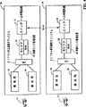
図2は、標準的なセルラー・システムの基本的な実施例を示したものであり、3つの単一セクタの基地局362、364及び368により構成される。図2においては、アンテナ310、326、及び344のそれぞれは、それぞれ基地局362、364及び368の受信アンテナに対応する。基地局362、364及び368は互いに近接して設置されており、アンテナ310、326及び344は互いにオーバーラップしたカバー・エリアを持っていて、1つのリモート・ユニットの信号が同時に3つの基地局との間でソフト・ハンドオフの状態となりうるような構成となっている。
アンテナ310、326及び344は、それぞれ受信信号を受信処理部312、328及び346に供給する。受信処理部312、328及び346は、RF信号を処理し、その信号をディジタルのビットに変換する。また、受信処理部312、328及び346は、ディジタル・ビットをフィルタすることもできる。受信処理部312は、フィルタ処理されたディジタル・ビットを復調エレメント316A−316Nに供給する。受信処理部328は、フィルタ処理されたディジタル・ビットを復調エレメント332A−332Nに供給する。同様に、受信処理部346は、フィルタ処理されたディジタル・ビットを復調エレメント350A−350Nに供給する。
復調エレメント316A−316Nは、相互接続320を介してコントローラ318によって制御される。コントローラ318は、復調エレメント316A−316Nを基地局362によって同じリモート・ユニットであると認識されるリモート・ユニットからの情報信号の1つのインスタンスに割り当てる。環境のマルチパス特性によって、信号のはっきりしたインスタンスが生成されることがある。復調エレメント316A−316Nは、データ・ビット322A−322Nを生成し、これらはシンボル・コンバイナ324の中で組み合わされる。シンボル・コンバイナ324の出力は、ビタビ・デコーディングに適したソフト判定データの集合である。組み合わされたデータは、デコーダ314によってデコードされ、メッセージ1として出力され、セルラー又はパーソナル通信のシステム・コントローラ370に受け渡される。
復調エレメント316A−316Nによって復調されたすべての信号の信号強度の組み合わせに従って、基地局362からリモート・ユニットへの電力調整コマンドが、コントローラ362によって生成される。コントローラ318は、リモート・ユニットへ中継される電力制御情報を基地局362の送信回路(図示せず)に受け渡すことができる。
復調エレメント332A−332Nは、相互接続336を通じてコントローラ334により制御される。コントローラ334は、復調エレメント332A−332Nを同じリモート・ユニットからの情報信号の1つのインスタンスに割り当てる。復調エレメント332A−332Nは、シンボル・コンバイナ340の中で組み合わされるデータビット338A−338Nを生成する。シンボル・コンバイナ340の出力は、ビタビ・デコーディングに適したソフト判定データの集合であっても良い。組み合わされたデータは、デコーダ342によってデコードされ、メッセージ2として出力され、セルラー又はパーソナル通信のシステム・コントローラ370に受け渡される。
リモート・ユニットへの電力調整コマンドは、復調エレメント332A−332Nによって復調されたすべての信号の信号強度の組み合わせに従ってコントローラ334によって生成される。コントローラ334は、リモート・ユニットへ中継される電力制御情報を基地局364の送信回路(図示せず)に受け渡すことができる。
復調エレメント350A−350Nは、相互接続352を介してコントローラ352によって制御される。コントローラ352は、復調エレメント350A−350Nを基地局368によって同じリモート・ユニットであると認識されるリモート・ユニットからの情報信号の1つのインスタンスに割り当てる。復調エレメント350A−350Nは、シンボル・コンバイナ358の中で組み合わされるデータビット356A−356Nを生成する。シンボル・コンバイナの出力は、ビタビ・デコーディングに適したソフト判定データの集合であっても良い。組み合わされたデータは、デコーダ360によってデコードされ、メッセージ3として出力され、セルラー又はパーソナル通信のシステム・コントローラ370に受け渡される。
リモート・ユニットへの電力調整コマンドは、復調エレメント350A−350Nによって復調されたすべての信号の信号強度の評価信号に従ってコントローラ352によって生成される。コントローラ352は、リモート・ユニットへ中継される電力制御情報を基地局368の送信回路(図示せず)に受け渡すことができる。
システムの中でソフト・ハンドオフのモードで動作している各リモート・ユニットに対し、セルラー又はパーソナル通信のシステム・コントローラ370は、少なくとも2つの基地局からデコードされたデータを受信する。例えば図2では、セルラー又はパーソナル通信システムのコントローラ370は、それぞれ基地局362、364及び368から、共通リモート・ユニットからのメッセージ1、2及び3の形でデコードされたデータを受信する。デコードされたデータを組み合わせることによって、データをデコード処理の前にデータを組み合わせることによって達成することのできる非常に有利な効果を得ることはできない。このため、典型的なセルラー又はパーソナル通信システムのシステム・コントローラ370は、各基地局からのデコードされたデータを組み合わせることはしないで、メッセージ1、2又は3の中から最も高い信号品質のインデックスを持っているものを選択して残りの2つを破棄する。図2では、セレクタ372がフレーム毎に選択処理を実行し、その結果をボコーダ又はその他のデータ処理ユニットに供給する。選択処理の詳細については、1995年8月25日に出願され、本発明の譲受人に譲渡された出願中(co-pending)の米国特許出願シリアル番号08/519、670、"COMMUNICARTION SYSTEM USING REPEATED DATA SELECTION"に説明されている。
シンボル・コンバイナ324、340及び358からの組み合わされているがデコードされていないデータ出力が、それぞれ基地局362、364及び368からシステム・コントローラ370に送られない理由は、復調処理では、データが非常に速いレートで生成されるためである。大きなデータのブロックは、デコード処理の中で使用されて、デコードされたシンボルを生成する。1つのデータ・シンボルをデコードするために必要なデータの量とデコードされたシンボル及び品質インデックスの指定に使用されるデータの量の比は、1000対1にもなる。この複雑さに加えて、このような大量のデータを転送する場合に不可欠な時間遅れは、非常に高速なリンクを使用しないかぎり、妨げることはできない。このため、システムの中の数百の基地局(このうちほとんどは、図2に示されていない)とシステム・コントローラ370の間を相互接続するシステムは、組み合わせに適したデコードされていないデータのかわりにデコードされたデータと品質表示のみを送出することによって、大幅に簡略化される。
組み合わされているがデコードされていない大量のデータを送信する複雑さに加えて、コストの面でもほとんど実現不可能なものとなる。システムの基地局は、一般的にシステム・コントローラから離れたところにある。基地局からシステム・コントローラのまでの経路は、一般的にT1インターフェイス・ラインのようなリースされた回線によって構成される。これらのラインのコストは、ほとんど搬送するデータの量によって決定される。このため、基地局からシステム・コントローラに送信されるデータの量を増加することは、コスト面から実現を困難なものとし、技術的にも実現を難しくする。
最適化されていないシステムでは、図2に関して説明されたソフト・ハンドオフの選択方法は、同じ基地局の各セクタを別個の独立した基地局として扱うことにより、セクタ化されている基地局にそのまま応用することができる。基地局の各セクタは、同じリモート・ユニットからのマルチパス信号を組み合わせ、デコードする。デコードされたデータは、基地局の各セクタによって直接にセルラ又はパーソナル通信システムのシステム・コントローラに送ることができ、あるいはデータの比較と選択を基地局において行い、結果をセルラー又はパーソナル通信のシステム・コントローラに送ることもできる。しかしながら、同一の基地局のセクタ間でのハンドオフの取扱いにおいてさらに有利な方法は、前述した米国特許出願シリアル番号No.08/144,903に説明されている。ソフター・ハンドオフを提供するための回路は、図3との関係で説明する。
図3では、アンテナ222A−222Cは、それぞれ各セクタに対する受信アンテナであり、アンテナ230A−230Cは、1つのセクタに対する送信アンテナである。アンテナ222Aとアンテナ230Aは、共通するカバー・エリアに対応し、理想的な状態では同じアンテナパターンを持っている。同様に、アンテナ222Bと230B、それにアンテナ222Cと230Cは、それぞれ、共通のカバー・エリアに対応する。図3は、アンテナ222A−222Cがオーバーラップしたカバー・エリアを持っており、単一のリモート・ユニットの信号が同時に2以上のアンテナで受信されるような一般的な基地局を示したものである。アンテナ222A−222Cは、図1に示すようなアンテナ・パターンを持っていても良いし、あるいはアンテナ222A−222Cのうちの1つ又は複数が分配アンテナであっても良い。
二度、図3を参照すると、アンテナ222A、222B及び222Cは、それぞれ受信した信号を受信処理部224A、224B及び224Cに供給する。受信処理部224A、224B及び224Cは、RF信号を処理し、その信号をディジタル・ビットに変換する。受信処理部224A、224B及び224Cは、ディジタル・ビットをフィルタ処理し、その処理結果であるディジタル・ビットをインターフェース・ポート226に供給するような構造としてもよい。インターフェイス・ポート226は、相互接続212を介したコントローラ200による制御の下で、3つの入力信号経路の1つを復調エレメント204A−204Nに接続してもよい。
復調エレメント204A−204Nは、相互接続212を通じてコントローラ200によって制御される。コントローラ200は、復調エレメント204A−204Nを単一のリモート・ユニットからの情報信号の1つのインスタンスに割り当てる。復調エレメント204A−204Nは、それぞれが単一のリモート・ユニットからのデータの評価を示すデータ・ビット220A−220Nを生成する。データ・ビット220A−220Nは、シンボル・コンバイナ208によって組み合わせられ、リモート・ユニットからのデータについての単一の評価を生成する。シンボル・コンバイナ208の出力は、ビタビ・デコーディングに適したソフト判定データの集合であっても良い。組み合わされたシンボルは、デコーダ228に受け渡される。
復調エレメント204A−204Nは、また、相互接続212を介して複数の出力制御信号をコントローラ200に供給する。コントローラ200に渡されるデータには、特定の復調エレメントに割り当てられた信号の信号強度の評価が含まれる。復調エレメント204A−204Nのいずれかは、復調している信号の信号強度評価を測定し、その評価をコントローラ200に供給する。
シンボル・コンバイナ208は、1つのセクタだけからの信号を組み合わせて出力を生成し又はインターフェース・ポート226により選択された複数のセクタからのシンボルを組み合わせることができる点に注意すべきである。単一の電力制御コマンドは、信号が受信されたすべてのセクタからの信号強度の評価に従ってコントローラ200によって生成される。コントローラ200は、電力制御情報を基地局の各セクタの送信回路に受け渡す。このように、基地局の各セクタは、単一のリモート・ユニットに対して同じ電力制御情報を送信する。
シンボル・コンバイナ208は、1つ以上のセクタを通じて通信を行っているリモート・ユニットからの信号を組み合わせているときは、そのリモート・ユニットはソフタ・ハンドオフの状態にある。基地局は、デコーダ228の出力をセルラー又はパーソナル通信システム・コントローラに送るような構造であっても良い。セルラー又はパーソナル通信システムのシステム・コントローラでは、この基地局又は他の基地局からのリモート・ユニットに対応する信号は、前述した選択処理を用いることによって、単一の出力を生成するために使用しても良い。
図3に示す送信プロセスは、エンド・ユーザからセルラー又はパーソナル通信システムのシステム・コントローラを通じたリモート・ユニットへのメッセージを受信する。このメッセージは、アンテナ230A−230Cのうちの1つ又は複数によって送出することができる。インターフェイス・ポート236は、このリモート・ユニットへのメッセージをコントローラ200による設定により、復調エレメント234A−234Cのうちの1つ又は複数に接続する。変調ユニット234A−234Cは、このリモート・ユニットへのメッセージを適当なPN符号によって変調する。変調エレメント234A−234Cによって変調されたデータは、送信処理部232A−232Cにそれぞれ受け渡される。送信処理部232A−232Cは、メッセージをRF周波数に変換し、その信号をアンテナ230A−230Cからそれぞれ適当な信号レベルで送信する。インターフェイス・ポート236とインターフェイス・ポート226は、特定のリモート・ユニットからの信号をアンテナ222A−222Cのいずれかを介して受信することは、必ずしも対応する送信アンテナ230A−230Cがその特定のリモート・ユニットへの送信を意味するものではないということから、独立に動作するといえることに注意しなければならない。また、各アンテナを通じて送られる電力制御コマンドは同じものであり、同一の基地局からのセクタ・ダイバーシティは、最適な電力制御動作にとってクリティカルなものではないということにも注意しなければならない。これらの優位性は、さらに、送信ゲーティング(transmit gating)と呼ばれる処理を通じて、前述した米国特許出願シリアル番号08/144,901及び08/316,155に示すように、システムの優位性とすることができる。
前述した電力制御の複雑さに加えて、2つの基地局が異なるスイッチによって制御されているときに、2又はそれ以上の基地局の間でのソフトなハンドオフを試みる場合には、電力制御の処理は一層複雑なものとなる。ブリージングの処理もまた、従来の電力制御の機構を複雑なものにする。本発明は、ブリージングを行っている1連の基地局を通じて、これらの基地局が異なるスイッチによって制御されている場合も含めて、電力制御の管理を提供するための方法と装置に関するものである。
[発明の概要]
集中化された電力制御方法及び装置によって一連の基地局に対する集中化された電力制御が実現される。集中化された電力制御は、無線リンク・管理装置(radio link manager)(RLM)によって行われる。リモート・ユニットがトラフィック・チャンネルを確立している各基地局は、各リバース・トラフィック・フレームに対応するパケットをセレクタに送出する。各フレームについては、利用可能な場合には、リモート・ユニットによって受信された最後のフォワード・リンク・フレームが削除されたもの(an erasure)としてデコードされたかどうかを示す削除表示ビット(erasure indication bit)(EIB)を含む。RLMは、フォワード・リンク電力制御計算システムを動作させフレーム毎の計算結果を得る。このフレーム毎の計算結果は、トラフィック・チャンネル利得(traffic channel gain)とパイロット・チャンネル利得(pilot channel gain)の望ましい比、GTc/Gpilot、を与える。このように計算される比は、リモート・ユニットとの間で通信を確立しているすべての基地局に送信される。
本発明では、リバース・リンクの電力制御の管理についての集中化も行っている。本発明の好ましい実施の形態においては、RLMは、選択処理の出力における合計フレーム誤り率(aggregate frame error rate)を計算する。RLMは、絶対リバース・スレッショルド値(absolute reverse threshold value)を算出し、リモート・ユニットとの間で通信を確立している各基地局に受け渡す。このリバース・スレッショルド値は、フレーム毎に受け渡すことができる。
【図面の簡単な説明】
本発明の特徴、目的、優位性は、以下に示す詳細な説明を、全体を通して対応する部分には同じ参照記号を付した付す空の図面に照らして解釈することによって、さらに明白なものとなろう。ここで、図面には、以下の内容が含まれている。
図1は、典型的な3セクタ基地局のアンテナ・パターンを示す図である。
図2は、3つの単一セクタ基地局からなる標準的なセルラー・システム(cellular system)の基本的な実施例を示す図である。
図3は、標準的なセルラー・システムの3セクタ基地局の基本的な実施例を示す図である。
図4は、それぞれが異なるスイッチによって制御される2つの異なる動作領域により構成される、基本的なCDMA通信システムを示す図である。
図5は、同一のスイッチによって制御される2つの異なる動作領域により構成される、基本的なCDMA通信システムを示す図である。
[好ましい実施の形態の詳細説明]
図4は、それぞれが異なるスイッチによって制御される2つの異なる動作領域により構成される、基本的な無線符号分割多重接続(CDMA)通信システムを示す。動作領域36は、無線通信システムを公衆電話網(public switch telephone network)(PSTN)に接続するスイッチ32によって制御される。動作領域38は、無線通信システムを公衆電話網(PSTN)に接続するスイッチ34によって制御される。動作領域36は、複数の基地局によって構成されるが、図4には、そのうち基地局14及び基地局16の2つのみが示されている。CDMA相互接続サブシステム(CDMA interconnect subsystem)(CIS)6は、動作領域36の基地局とセレクタのバンク(bank)並びに図4に示されていない他の装置とを相互接続する機能を実現する。特に、CDMA相互接続サブシステム6は、リモート・ユニット10及びリモート・ユニット10に対応する呼出信号(call signal)を処理するセレクタ24との間での接続を確立することのできる基地局間での接続を提供する。
リモート・ユニット10が基地局14のみを介してアクティブ(active)なトラフィック・チャンネル通信リンクを確立しているときには、基地局14は、CIS6を介してデコードされたフレーム・データをセレクタ24に受け渡す。セレクタ24は、ボコードされたフレームをパルス・コード変調された(pulse code modulated)(PCM)データに変換するボコーダにより構成され、PCMデータをスイッチ32に受け渡す。基地局14からセレクタ24に到達するデータ・パケットは、基地局14とリモート・ユニット10の間の無線リンクについての情報を構成することもできる。セレクタ24は、無線リンクについての情報を無線リンク管理装置(RLM)22に受け渡す。
公衆電話網(PSTN)からリモート・ユニット10へのPCMエンコードされたデータは、スイッチ32からセレクタ24に受け渡される。PCMデータは、セレクタ24によってボコーダ・フレーム・データに変換される。ボコードされたフレームは、CIS6を介して基地局14に受け渡される。RLM22により、制御データをボコードされたフレームに付加(append)することもできる。リモート・ユニット10は、自動車電話(a vehicle based telephone)、携帯型ユニット(a hand-held portable unit)、PCSユニット又は固定的な無線ローカル・ループ・ユニット(a fixed location wireless local loop unit)若しくはその他の音声(voice)あるいはデータ通信装置とすることができる。
動作領域36では、RLM22がリモート・ユニット10と、リモート・ユニット10との間でアクティブな通信を確立している任意の基地局との間における無線リンクの無線インターフェイス(air interface)を制御する。本実施例では、RLM22の主要な機能の1つは、フォワード・リンクの電力制御及びリバース・リンクの電力制御の双方の動作を制御することである。フォワード・リンクの電力制御は、基地局が、リモート・ユニットによって測定されるフォワードフォワード・リンクの性能(performance)に基づいてリモート・ユニットに送信するフォワード・リンク・トラフィック・チャンネル信号のレベルを制御することによって行われる。リバース・リンクの電力制御は、リモート・ユニットが、リバース・リンクの性能に基づいて基地局に送信するリバース・リンク・トラフィック・チャンネル信号のレベルを制御することによって行われる。
リモート・ユニットは、ビット・エネルギーとノイズ電力密度との比(Eb/No)の定期的な測定又は削除されたもの(an erasure)としてデコードされたフレームの数がスレッショルド値を超える毎にメッセージを送出する等のいくつかの方法のいずれかによってフォワード・リンクの性能を測定することができる。好ましい実施の形態では、リモート・ユニットからのフォワード・リンク電力制御情報は、一般的に単にIS−95と呼ばれる”Mobil Station-Base Station Compatibility Standard for Dual-Mode Wideband Spread Spectrum Cellular System”、TIA/EIA/IS−95に基づいている。
IS−95においては、基地局がフォワード・トラフィック・チャンネル電力制御をイネーブル(enable)すると、リモート・ユニットは、電力測定報告メッセージ(Power Measurement Report Message)を使用してフレーム誤り率(FER)の統計結果を基地局に報告する。基地局は、リモート・ユニットが特定の時間間隔におけるフレーム誤り率の統計結果を報告するように、周期的な報告動作をイネーブルすることができる。基地局は、また、リモート・ユニットがフレーム誤り率が所定のスレッショルド値に達した場合にフレーム誤り率の統計結果を報告するように、スレッショルド報告動作をイネーブルすることができる。これは、IS−95のセクション7.6.4.1.1、the base station may use the reported frame error rate statistics to adjust the transmit power on the forward traffic channel"に基づく。注目すべき事実として、IS−95は、基地局がフレーム誤り率に基づいてフォワード・リンクの電力制御を行う際の具体的な方法を規定していないため、基地局を設計する各製造業者は、フォワード・リンクの電力制御を行うために異なる方法を自由に設計することができることである。
好ましい実施の形態では、リモート・ユニットからのフォワード・リンク電力制御情報は、また、一般的にJ−Standard 8と呼ばれる”Personal Station-Base Station Compatibility Requirements for 1.8 to 2.0 GHz Code Division Multiple Access(CDMA)Personal Communication Systems”AN−SI J−STD−008又は一般的にIS−95−Aと呼ばれる”Mobil Station-Base Station Compatibility Standard for Dual-Mode Wideband Spread Spectrum Cellular System + Telecommunication System Bulletin: Support for 14.4kbps Data Rate and PCS Interaction for Wideband Spread Spectrum Cellular Systems”TIA/EIA/IS−95-A + TSB74に対応させることができる。IS−95−Aにおいては、リモート・ユニットは、モービル・ステーション(a mobile station)と呼ばれる。J-Standard8では。リモート・ユニットは、パーソナル・ステーション(personal station)と呼ばれる。
IS−95−A及びJ-Standard8では、リモート・ユニットは、2つのモードのうちのいずれかで動作する。第一のモードは、IS−95標準におけるリモート・ユニットの動作に基づくものであり、レート・セット1(Rate Set1)と呼ばれる。動作の第二の形式は、異なるデータ・レート(date rate)のセットでの動作に基づくものであり、レート・セット2(Rate Set2)と呼ばれる。レート・セット2のデータ・レートは、レート・セット1のデータ・レートよりも高い。リモート・ユニットがレート・セット2で動作しているときは、リバース・リンクで送信される各フレームは、削除表示ビット(EIB)を構成する。このEIBビットは、削除されたものとしてデコードされるフォワード・リンク・フレームを受信した後に‘1’にセットされる。その他のすべての場合には、EIBは‘0’にセットされる。表Iに、2つのレート・セットのそれぞれの4つのレート・セットについて、フレーム当りの情報ビットの数を示す。リバース・トラフィック・チャンネルにおける削除には、情報ビットは割り当てられない。

従来技術における典型的な例としては、図4に示すRLM22のような無線リンク・管理装置がスレッショルド値を制御する。このため、リモート機器の‘スーパー・ユーザ’(super user)について他のシステム・ユーザより低いFERが保証された場合には、そのリモート・ユニットとの通信を確立している各ベース・ステーションに対して無線リンク管理装置からメッセージを送出することによってスレッショルド値を変更することができる。
リモート・ユニットがハンドオフの状態にあるときには、図2に示す基地局のセクタと関連して説明されている方法に非常によく似た方法により、複数の基地局からのマルチパス信号の数を組み合わせることによって生成される総合計信号(total aggregation signal)に基づいてFERを測定する。基地局における変復調の動作とリモート・ユニットにおける変復調の動作の違いは、リモート・ユニットは、ハンドオフの間2つの異なる信号源(source)からの信号を受信するのに対し、基地局は、リモート・ユニットがハンドオフの状態にあるかどうかにかかわらず、同一のリモート・ユニットからの複数のマルチパス伝達信号(multipath propagation signal)を受信するという点にある。リモート・ユニットは、信号を生成した基地局の別に関係なく信号の各マルチパス・インスタンス(instance)に対応するパイロット信号の相対信号強度に基づいて復調エレメントの出力を組み合わせる。このように、IS−95では、リモート・ユニットは、合計デコード信号に基づいて1つのFER測定を実行して、このFER測定結果をリモート・ユニットが通信を行っている各基地局に送信する。IS−95−A及びJ-Standard8では、リモート・ユニットは、FER測定結果ではなく合計信号に基づいて、単に、各フレームと共にEIBを送出することとすることができる。
リモート・ユニットとの通信を行っている各基地局は、FERをスレッショルド値と比較して、対応するフォワード・リンク・トラフィック・チャンネルの送信電力レベルを増大させ、減少させ、又はこれをそのまま維持する。ここで、このようなシステムの欠点に留意されたい。各基地局が同じ計算方法と同じスレッショルド値を用いている場合でも、リモート・ユニットのサービスに対して同じ優先順位を持った2つの基地局は、そのリモート・ユニットに対して異なるレベルで信号を送信する場合がありうる。このような異なるレベルは、各基地局の出力の絶対電力レベルが、計算システムの動作が開始される際の初期値に依存していることにより発生する。リモート・ユニットが動作領域の中を移動すると、ハンドオフがランダムな時間間隔によって開始し、新しく追加された基地局のトラフィック・チャンネル電力レベルの初期絶対値は、リモート・ユニットがすでに通信を行っている他の基地局によって用いられているトラフィック・チャンネル電力レベルとは無関係である。ここで、新しい基地局が追加された時点で、リモート・ユニットがすでに適正なFERで動作している場合を考える。新しく追加された基地局のトラフィック・チャンネル電力レベルの初期値が低い場合には、新しく追加された基地局の信号電力がリモート・ユニットのFERに与える影響は最小限のものとなる。リモート・ユニットにおけるFERがすでに受容可能なものであるため、新しく追加された基地局の送信電力は初期値のままである。このように、もとの基地局の優先順位が新しく追加された基地局と同じ優先順位を持っており、もとの基地局が新しく追加された基地局によって使用される初期値よりも高い電力レベルで送信を行っている場合には、これらの基地局の双方における送信レベルは一定であるが異なる値となる。このように、あるリモート・ユニットに対して同じ優先順位を持った2つの基地局が、2つの異なる絶対電力レベルでトラフィック・チャンネル信号を生成する場合がありうる。システム的な観点からは、このようなバランスを欠いた動作によって、最も高いレベルで信号を送信する基地局から他のリモート・ユニットに対する不当な妨害を引き起こすことが考えられる。
2つの異なるトラフィック・チャンネルが異なる値を持っている場合でも、リモート・ユニットへのサービスについて同じ優先順位を持っている場合には、各基地局のパイロット信号強度は、リモート・ユニットによって測定されるものと同じになる。リモート・ユニットでは、パイロット信号の相対信号強度に基づいて組み合わせ動作が行われる。組み合わせ処理は、同じ強度を持ったパイロット信号に基づいて強度の異なるトラフィック・チャンネル信号を組み合わせる場合には、最適状態には及ばない状態において(in a suboptimal fashion)行われる。
また、上述した理由から、各セクタによって送信される相対電力を適正に制御することによってハンドオフの境界が各基地局の間で適正に配置されるようにすることが重要である。このバランスを保持するための処理は、“基地局ブリージング”(base station breathing)の処理によって実現される。前述した米国特許に詳述されているように、基地局ブリージングの処理の間では、基地局の総出力電力は送受信電力にもとづいて制御される。ブリージング処理は、基地局の総合計出力電力に基づいて行われるため、任意のトラフィック・チャンネルに対して電力制御機能(power control mechanism)によって生成される‘絶対値’は、基地局によって実際に送信されるレベルの評価にすぎない。ブリージングによる優先順位処理効果(overriding effect)のため、電力制御機能によって返される同一の‘絶対値’は、基地局の負荷状態に応じて随時変化する実際の送信電力レベルの変動を反映する。
このシステムのもう1つの優位性は、大規模な通信システムに様々な最大信号レベルを持った基地局が含まれている場合に発揮される。例えば、大きな基地局では合計20ワットの送信を行うことができるのに対し、小さな基地局では1ワット又はそれ以下の出力のみを送信可能な小さなカバー・エリアに対するサービスを行っている。このように、‘絶対的な’レベルを算出するための計算システムは、さらに不明確なものとなる。
本発明による構成のさらなる優位性としては、電力制御機能を集中化し、システム全体を通じてパイロット信号強度に関連した統一的な電力制御を行うことによって、従来技術の欠点を克服できることが挙げられる。
前述したように、各基地局から送信される合計フォワード・リンクCDMA信号の電力は、合計フォワード・リンク・信号を生成するために組み合わされる信号の数とその相対電力の関数となる。例えば、合計フォワードリンク信号には、ページング・チャンネル、パイロット信号、同期チャンネル及び複数のトラフィック・チャンネルを含めてもよい。このように、システム中の各セクタは、そのセクタが送信する信号の数、相対信号強度及びデータ・レートに基づいて独立した合計信号強度を持っている。好ましい実施の形態では、フォワード・リンク信号出力を生成する各変調エレメントは、その生成する信号レベルを示すディジタル信号を出力する。各変調エレメントの出力表示は、他の出力表示に加算される。このような方法により、合計信号レベルの表示が生成される。合計信号強度を示すフォワード・リンク・ゲイン信号を生成するするための方法及び装置については、本発明の譲受人に譲渡された1995年9月8日出願の米国特許出願シリアル番号No.08/525,899、”APPARATUS AND METHOD FOR CONTROLLING TRANSMISSION POWER IN A CELLULAR COMMUNICATIONS SYSTEM”に詳述されている。
このような電力制御構造により、基地局から送信されたパイロット信号のレベルに対して、各トラフィック・チャンネル信号の電力を相対的に定めることが容易となる。例えば、基地局についてトラフィック・チャンネル利得(GTc)対パイロット・チャンネル利得(Gpilot)の値が与えられている場合には、基地局は、そのように与えられた比の値にパイロット・チャンネル電力を乗じてトラフィック・チャンネル電力の計算値を得ることができる。このように、基地局は、電力制御のアルゴリズムを実行せずに、単に、比に送信しているパイロット信号電力を乗ずる。
本発明では、集中化された電力制御はRLMによって制御される。RLMは、電力制御計算システムを動作させる。ここで再び図4を参照すると、動作領域36においてリモート・ユニット10との間でトラフィック・チャンネルを確立している各基地局は、各フレームに対応するパケットをセレクタ24に送出する。パケットは、使用中のデータ・セット、複数の基地局からのアライニング・データ(aligning data)のシーケンス番号及びフレームに対応するデータ・レートを含んでいる。対応するフレームがレート・セット1で動作している場合には、リモート・ユニットは、FERを含むメッセージを繰り返し送出する。対応するフレームがレート・セット2で動作している場合には、EIBが含められる。
リモート・ユニットがレート・セット1で動作している場合には、セレクタ24は、FER情報をRLM22に受け渡す。RLM22は、フォワード・リンク電力制御計算システムを動作させて、フレームあたり1つの計算結果を得る。フレーム当たりの計算結果は、望ましいGTc/Gpilotの比である。この望ましい比は、リモート・ユニット10との間で通信を確立している基地局に送信される。リモート・ユニットによるFERの測定結果は、実際にはフレームのセットにわたるFERの平均値である。このため、このような電力制御システムにおいては、本質的に遅延が存在する。
リモート・ユニットがレート・セット2で動作している場合には、セレクタ24は、EIB情報をRLM22に受け渡す。RLM22は、フォワード・リンク電力制御計算を実行してフレームあたり1つの計算結果を得る。このフレーム当たりの計算結果もまた、望ましいGTc/Gpilotを与えるものである。計算された比は、リモート・ユニット10と通信を確立している基地局に送信される。EIBは、リモート・ユニットからフレーム毎に送出される。このため、FERの測定に固有の遅延を取り除くことができる。EIBを用いる場合の他の利点としては、1ビットの長さを持つに過ぎないため、パケット内でのより効率的なビット割り当てが可能になるという点がある。
本発明の優位性は、システム全体としての容量を制御しうる点にある。また、最小動作FERを選択することによってもシステムの容量を設定することができる。より高いFERを用いる場合には、より小さなFERを用いる場合よりも多くの容量で動作することができるため、より多くのユーザに対応することができる。システムのFERが集中的に制御されるため、システム全体のFERの値は、RLMによって使用される計算のシステムを変更することによって制御することができる。このようにして、大きなトラフィックが要求される場合には、その領域内でおいて対応するFERの値を一時的に大きな値とすることにより、すべてのユーザについての信号品質の劣化と引き換えにより多くのユーザに対応することができる。
また、本発明によれば、ある基地局の動作点(operating point)を他の基地局との関係において変更することが容易である。例えば、ネットワーク計画の不備により、ある基地局が要求カバー・エリアを提供できない場合がある。また、基地局が、例えばアンテナが損傷すると、一時的に障害を発生する場合がある。GTc/Gpilotの値を隣接する基地局における値に比べて大きく設定することにより、その基地局の相対的な性能を向上させ、リモート・ユニットにおける隣接基地局からの信号への依存度を低下させることができる。
本発明の他の大きな優位性は、各フレームの利得を独立に調整できることである。シーケンスの中の特定のフレームが、他のフレームよりも重要度が大きい場合を考える。例えば、あるフレームが他のシステムへのハード・ハンドオフの表示を含んでいる場合には、リモート・ユニットによってメッセージが受信されなければならず、受信が行われない場合には、通信は維持されない。受信を確実に行うためには、このようなメッセージをリモート・ユニットに供給する際の相対電力を増加させることが有利である。本発明では、特定のフレーム又はフレームのセットについての電力の増加を比較的容易に行うことができる。RLMは、問題とされるフレームに対応するGTc/Gpilotの比を増加させ、問題とされるフレームが終了した後にGTc/Gpilotの比を通常の動作状態におけるレベルに戻す。
各基地局が、その送信するパイロット信号に比較して同じ相対レベルでトラフィック・チャンネルを送信しているときには、同じ優先順位を持った基地局がリモート・ユニットに異なる信号レベルを持つ場合の問題は解消される。また、この場合には、トラフィック・チャンネル及びパイロット・チャンネル利得は基地局間で一定の比を持っているため、最適化されない組み合わせ動作(suboptimal combining)の問題も解消される。ブリージング及びブラッサミングの処理は、ブリージング及びブラッサミングの動作の双方が基地局の合計送信電力に基づいて行われ、トラフィック・チャンネル利得対パイロット・チャンネル利得の比を変更しないものであるため、本発明とよく整合する。
集中化された電力制御は、リバース・リンクの電力制御動作においても大きな優位性を持っている。図2は、基地局362、364及び368がボコーダ・データのフレームをセレクタ372に供給する典型的な構成を示したものである。好ましい実施の形態では、図4では、図2に示した構造を組み込んでいる。図4では、選択の処理は、好ましい実施の形態では、前述した米国特許出願シリアル番号No.08/519,670に対応するセレクタ24によって実行される。
リモート・ユニットとの間で通信を行っている各基地局は、各フレーム毎に、評価データ・レート(estimated data rate)、評価データ(estimated data)及び信頼性ファクタ(confidence factor)を含むデータ・パケットを供給する。セレクタ24は、最も大きな信頼性ファクタを持ったフレームを選択して、これをボコーダに受け渡す。セレクタ24は、受信した評価データの残りを破棄する。セレクタ24の出力における誤り率が算出される。リモート・ユニットがソフト・ハンドオフの状態にあるときには、選択処理に対してデータを供給する複数の基地局が存在するため、各基地局からの入力FERは、選択処理の出力において得られる望ましいFERを遥かに超えたものとなる。例えば、典型的なCDMAシステムにおいて、3つの基地局が選択処理にフレームを供給している場合には、各基地局はFERの値として30%もの値を持っていたとしても、選択処理の出力ではFERとして1%程度の望ましい値を得ることができる。各基地局からのFERの値は、最も好ましいEb/Noの値を持ったリモート・ユニット信号を受信する基地局においてFERの平均値が最低となる場合には、他の基地局からの値とは一般的に異なったものになる。
リバース・リンクにおける電力制御は、リモート・ユニットが通信を行っている相手方の基地局によって制御されるリモート・ユニットからのリバース・リンク信号の送信電力レベルによって設定される。各基地局は、受信するマルチパス信号を組み合わせる。基地局がソフト・ハンドオフの機能を有する場合には、基地局は、異なるセクタからの信号を組み合わせることによってデコーダへ入力する1つの信号を生成することができる。デコーダは、合計復調データを受信してリモート・ユニットによってエンコードされる信号のデータ・レート、実際のデータの評価及び信頼性ファクタの決定を試みる。信頼性ファクタは、デコーダがそれによって評価データを選択する、信頼性を羽根医する。このようなデコーダの動作についての情報は、本発明の譲受人に譲渡された1994年4月26日出願の米国特許出願シリアル番号No.08/233,570、”METHOD AND APPARATUS FOR DETERMINING DATA RATE OF TRANSMITTED VARIABLE RATE DATE IN A COMMUNICATIONS RECEIVER”に開示されている。
各基地局のデコーダ出力においては、FERが計算される。従来技術によるリバース・リンク電力制御ループでは、フレーム毎にFERをスレッショルド値と比較する。FERがFERのスレッショルド値を超えると、基地局は、リモート・ユニットに送信電力レベルを増加させるためのコマンドを送出する。FERがFERのスレッショルド値より小さい場合には、基地局はリモート・ユニットに送信電力レベルを減少させるためのコマンドを送出する。リモート・ユニットは、そのリモート・ユニットが通信を行っているすべての基地局が電力レベルの増加を要求する場合に限り、送信信号レベルを増加させる。リモート・ユニットは、そのリモート・ユニットが通信を行っている基地局のいずれかが電力レベルの減少を要求する場合には、送信信号レベルを減少させる。一般的には、リモート・ユニットと通信を行っている1つの基地局が、そのリモート・ユニットに対する最も優位な通信経路を持っている。他の基地局は、そのリモート・ユニットからの電力レベルの増加を絶え間なく要求するであろう。このように最も有利な接続を有する基地局は、増加の要求を他の要求とともに送出し、リモート・ユニットはその送信電力を増加させる。したがって、通常のハンドオフ動作では、最も有利な接続を持った基地局が、リモート・ユニットの出力電力を実際に制御する。
従来技術によるフォワード・リンク構成と同様に、従来技術によるリバース・リンクの電力制御構成では、FERスレッショルド比較値は、RLM22によって制御される。RLM22は、各基地局に対して選択処理の出力における合計FERに基づいてその使用しているスレッショルド値を増加又は減少させるコマンドを伝送する。従来技術によるフォワード・リンク制御機構と同様に、各基地局が同じアルゴリズムによって動作している場合には、各基地局は計算システムの動作を同時に開始せずあるいはスレッショルド値を共通とするための関連付けもなされていないため、スレッショルド値は基地局ごとに異なる場合がある。このため、同じFERを持ったリモート・ユニットからの信号を受信する2つの基地局は、FERを異なるスレッショルド値と比較することがある。リモート・ユニットからの信号をより大きなスレッショルド値と比較する基地局が、実際にリモート・ユニットの電力レベルを制御することとなる。より小さなFERのスレッショルド値を持つ基地局は、リモート・ユニットに対してその送信電力レベルを増加させるためのコマンドを連続して送信する場合があるが、リモート・ユニットは、少なくとも他の1つの基地局が送信電力レベルの増加を要求していない限りこのようなコマンドには応答しない。選択処理の出力における合計FERが受容可能なものである限り、RLMは、いずれの基地局においてもスレッショルド値を変更しない。
このような構成においては、より高いFERのスレッショルド値を持っており、リモート・ユニットの電力レベルを実際に適正なレベルに制御している基地局が、リモート・ユニットとの接触(contact)を失った場合に問題を生じる。この場合には、より小さなFERのスレッショルド値を用いている基地局が、リモート・ユニットの動作を制御することを開始する。このようにして、リモート・ユニットは、その送信電力を増加させ始める。しかしながら、リモート・ユニットは、すでに、セレクタの出力側で適正なFERを生成するように動作しているため、一般には電力の増加は必要とされない。このように、リモート・ユニットは、RLMスレッショルド値制御ループがFERの不適当な減少を検出するまで、その送信電力を不必要に増加させ、そのような不適切な動作をしている基地局(offending base station)を含むすべての基地局のFERのスレッショルド値を増加させる。FERのスレッショルド値が増加してリバース・リンク電力制御ループが応答するまで、システム中で動作する他のリモートユニットに不当な妨害を与え、また、これにより、これらのユニットからの誤り率を高いものとする。不適当な動作をする基地局でのスレッショルド値が必要なFERのスレッショルド値に比べて非常に高い場合には、ループの応答時間は、かなり長いものとなる。このように電力制御動作が最適に行われない場合には、システム全体としての容量が減少する。
この問題を緩和するために、本発明では、電力制御の機能を再びRLMに移行させる。好ましい実施の形態では、RLM22は、選択処理の出力での合計FERを計算する。合計FERは、リモート・ユニット10との間でアクティブな通信が確立されている各基地局によって使用される絶対リバース・スレッショルド値を計算するシステムに入力される。再び、このリバース・スレッショルド値は、フレーム毎に渡される。セレクタ24及びRLM22に渡される情報は、従来技術と本発明において同一であることに注意されたい。本発明のもう1つの優位性として、システム全体の容量を制御できる点がある。選択された最小動作FERも、システムの容量を設定する。より高いFERのレートが使用される場合には、低いFERを使用した場合に比べて容量が大きくなるため、同じシステムでより多くのユーザに対応することができる。システムのFERは、計算システムによって制御されるため、システム全体のFERは、RLPによって使用される計算システムを変更することによって制御することができる。このように、トラフィックが大きい時には、その領域内の対応するFERを一時的に増加させることによって、すべてのユーザの信号品質の劣化と引き換えにより多くのユーザに対応することができる。
基地局において、リモート・ユニットからのデコードされたフレームのFERを計算して、その結果を絶対FERの形で与えられるリバース・スレッショルド値と比較することとしてもよい。しかしながら、絶対スレッショルド値は、必ずしもFERスレッショルド値の形をとる必要がないことに注意されたい。例えば、好ましい実施の形態では、リバーズ・スレッショルド値は、対応するリモート・ユニットによって生成される復調されたウォルシュ・シンボル(Walsh symbol)のエネルギーとRFチャンネルにおける総合電力スペクトル密度の比である。リバース・リンクの性能の測定としては、任意のものを使用することができる。
システムの各基地局がリバース・スレッショルドを用いて動作しており、1つの基地局との間における通信が失われた場合には、残りの基地局は、直ちにそのリモート・ユニットへの有効な電力制御コマンドの供給を開始する。このようにして、電力制御が最適な状態から外れることはなく、また、システム全体としての容量は維持される。
他の優位性としては、新しい基地局がリモート・ユニットとの通信を開始すると、これらの基地局に対して適正な動作レベルが渡されることである。従来技術による方法では、新しい基地局がリモート・ユニットとの通信を開始してからその基地局がリバース・リンク動作のための適正なリバース・スレッショルド値に追従するまでの間に、固有の遅延時間が存在していた。本発明では、絶対及び適正な値が、動作が開始するときに直ちにリモート・ユニットに伝送される。
集中化された電力制御の簡潔性は、相互接続動作が行われるときにより明白となる。再び図4を参照すると、動作領域38は、第二のシステムに対応する。動作領域38は、ことなるキャリアによって動作するものでもよい。動作領域38は、異なる会社によって製造された設備を含んでいてもよく、動作領域36の設備と異なる方法で動作をするものであってもよい。
動作領域38は、複数の基地局を含むものであり、図4には、このうち基地局18及び20の2つのみが示されている。CDMA相互接続システム(CIS)8は、動作領域38の基地局とセレクタのバンク並びに図4に示されていない他の装置とを相互に接続する機能を提供する。特に、CIS8は、リモート・ユニット12との接続を確立しうる基地局とリモート・ユニット12に対応する呼出信号を処理しうるセレクタ28との間の接続を提供する。
リモート・ユニット12が基地局18のみを介してアクティブなトラフィック・チャンネル通信を確保したときは、基地局18は、デコードされたフレーム・データをCIS8を介してセレクタ28へ渡す。セレクタ28は、ボコードされたフレームをパルス・コード変調(PCM)データに変換するボコーダにより構成され、PCMデータをスイッチ34に受け渡す。基地局18からセレクタ28に到達するデータ・パケットは、基地局18とリモート・ユニット12の間の無線リンクについての情報を含むこともできる。セレクタ28は、無線リンクについての情報を無線リンク管理装置(RLM)26に受け渡す。
PCMエンコードされたデータは、スイッチ34からセレクタ28へ渡される。PCMデータは、セレクタ28内でボコードされたフレーム・データに変換される。ボコードされたフレームは、CIS8を介して基地局18に渡される。RLM26により、無線リンク制御データをボコードされたフレームに付加することもできる。
リモート・ユニット12は、好ましい実施の形態では、IS−95、J-Standard、IS-95-A又はその他の技術基準に基づいて動作するリモート・ユニット10と同様な動作をする。リモート・ユニット12は、自動車電話、携帯型ユニット、PCSユニット又は固定的な無線ローカル・ループ・ユニットあるいはその他の音声もしくはデータ通信装置とすることができる。
動作領域38の中だけで動作するときには、RLM28は、リモート・ユニット12と、リモート・ユニット12との間でアクティブな通信を確立している任意の基地局との間の無線インターフェイスを制御する。再び、RLM26の主要な機能の1つは、フォワード・リンクの電力制御機能及びリバース・リンクの電力制御機能の双方の動作を制御することである。
相互接続動作は、リモート・ユニット12が動作領域38にある基地局18との間でアクティブな通信の状態にあり、動作領域36に近づいたときに開始する。リモート・ユニット12が基地局16のカバー・エリアに入ると、リモート・ユニットはこれを基地局18に通知する。この時点では、理想的なシステムにおいては、リモート・ユニット12は、基地局16と基地局18との間でのソフトなハンドオフの状態となる。しかしながら、異なる動作領域にある基地局の間でのソフトなハンドオフには、いくつかの問題点がある。
第1の問題点は、CIS8が基地局16に対して直接に接続されない点である。この問題点は、いくつかの方法のいずれかによって克服できる。EIA/TIA/IS−41C、”Cellular Radio Intersystem Operations”は、一般にIS−41と呼ばれる。IS−41は、異なる動作領域のスイッチ間における通信に対して、ハードなハンドオフをサポートするための技術標準を定義する。IS−41では、現在のところシステム間におけるソフトなハンドオフをサポートするためのプロトコルを提供していない。ある実施例においては、リモート・ユニット12からの必要な情報は、セレクタ24、スイッチ32を介して基地局16からCIS6へ渡すことができる。スイッチ32からは、この情報は、IS−41のような接続又はその他の接続を用いてスイッチ34に渡される。スイッチ34からは、この情報はセレクタ28に渡すことができる。ここに説明した経路のミラー処理を行うリバース経路は、リモート・ユニット10へ送信するために、情報をセレクタ28から基地局16へ返送する。このようなスイッチ・トゥ・スイッチ接続(switch−to−switch connection)における引き伸ばされた特質は、不必要な遅延時間を発生し、不必要な資源の消費にもつながる。
第二の接続の方法を図5に示す。EIA/TIA/IS−634、”MSC-BS Interface for Public 800MHz”IS−634は、動作領域間における接続の技術基準を定めるものであり、ソフトなハンドオフをサポートする。IS−634の基本的な実施例を図5に示す。図5では、図4に示したのと同様のエレメントには同様の参照識別子を用いている。スイッチ34は取り除かれ、スイッチ32により、動作領域38にある基地局とPSTNの間及び動作領域36にある基地局とPSTNとの間の接続を行っている。
基地局16とセレクタ28の接続を行うためのより効率的な第三の方法は、CIS6をCIS8に接続することである。CIS6とCIS8の間の接続も図5に示す。この接続は便利であるが、異なるシステムにおいてアーキテクチャが大きく異なるため、現実の産業界においては効果的な方法ではない。接続40のような接続を設けることができるのは、動作領域36と動作領域38が非常によく似た構造となっている場合に限られる。しかしながら、このような効率的な接続を利用できる場合には、本発明の原理を直接に適用することができる。
第二の問題は、電力制御のパラメータを算出するために用いられる方法が2つの動作領域において異なることである。本発明では、2つのシステムの間で3つの電力制御制御情報、即ち、EIB(又はFER)、GTc/Gpilot及びリバース・スレッショルド値が伝送される。これらの3つの情報から、いくつかの方法の1つが、電力制御ループを制御するために用いることができる。従来技術における値は、2つのシステムの間で伝送されるパラメータを本発明の電力制御プロトコルにしたがって積算することによって得られることに注意されたい。
例えば、リモート・ユニット12が基地局16のカバー・エリアに入る上述の例を再び参照し、動作領域38が、従来技術に基づいてモデル化された電力制御方法を使用しているものとする。また、リモート・ユニット12は、レート・セット2によって動作しているものとする。このようなケースでは、フォワード・リンクの電力制御ループを制御するために、RLM26は、各基地局が用いているスレッショルドを認識しないままに、その制御の基でターン・アップ(turn-up)及びターン・ダウン(turn-down)スレッショルド表示を基地局に送出し、リモート・ユニット12は、各フレームとともにEIBを送出する。動作領域36は、本発明の電力制御プロトコルにしたがって(また、動作領域36が集中化された電力制御で動作しているかどうかに関係なく)動作するため、RLM26は、IS−634リンクを介して基地局16からEIB表示を受け取る。RLM26は、動作領域38にある基地局で用いられているものと類似の又は異なる計算システムを用いて基地局16に対して対応するGTc/Gpilotの値を計算することができる。RLM26は、さらに、GTc/Gpilotの値をIS−634リンクを介してCIS−6に渡す。
動作領域36が本発明に対応する電力制御機能を使用している場合には、基地局16は、GTc/Gpilotの値を用いて、対応するフォワード・リンク・トラフィック・チャンネルの電力レベルを直接に設定することができる。動作領域36が従来技術による電力制御機能を使用している場合には、基地局16は、リモート・ユニット12に対して送信している信号の電力レベルを増加又は減少すべきことを示すコマンドの受信を待つ。この場合には、基地局16又はRLM22が、最後のGTc/Gpilotの値を現在のGTc/Gpilotの値と単に比較し、適正な増加又は減少のコマンドを生成する。このように、本発明の電力制御プロトコルによれば、従来技術による電力制御システムとの強調動作を容易に行うことができる。
上述の類似の機能は、リバース・リンクの電力制御において実現可能なことに留意されたい。本発明の電力制御プロトコルは、通信がIS−634リンク、IS−41リンク又は他のリンクのいずれにおいて行われる場合でも等しく良好に動作する。現実のアーキテクチャでは、本発明の電力制御プロトコルを使用する場合でも、機能の割り当てと通信リンクの経路は2つの動作領域の間でかなり異なったものとなる。
本発明の電力制御プロトコルのもう1つの特徴は、動作システムの間で3つのデータを転送するために使用される実際のビット割り当てとフォーマットである。データのフォーマットは、動作システム間で一致していなければならず、したがって通信業界において標準化されるべきものである。IS−634は、それによって統一したシステム間の通信が定義される機能を提供するものである。
一般的には、動作領域は、標準的な64キロビット毎秒(kbit)又は56kbitのディジタル・チャンネルであるDSΦリンクによって接続される。DSΦリンクは、物理インターフェイス層又はレイヤ1と呼ばれる。各ディジタル・チャンネルは、ソフト・ハンドオフで単一のリモート・ユニットをサポートするために使用される。64kbitのディジタル・チャンネルは、4つの16kbitサブレート・チャンネル(subrate channel)に分割される。56kbitディジタル・チャンネルは、3つの16kbitサブレート・チャンネルに分割される。サブレート・チャンネルは、例えば、各サブレート・チャンネルがDSΦの8ビットのうちの2ビットを占めるといった方法でディジタル・チャンネルの上にマルチプレクス(multiplexed)される。1つのディジタル・チャンネルは、そのリモート・ユニットが通信を行っている最大4つまでの異なる基地局からの単一のリモート・ユニットへの対応するデータを伝送するために使用される。
好ましい実施の形態では、レイヤ2のフレーム構造は320ビットを占める。最初の16ビットによってフラグが指定される。このフラグは、データ・フレームの開始を示す。好ましい実施の形態では、フラグの値は16進において06B9である。次のビットのセットによって、情報フィールドが構成される。情報フィールドの中の情報ビットの数は、以下に説明するようにレート・セットとデータ・レートによって異なったものとなる。情報フィールドに続いて、フレーム・チェック・シーケンスが置かれる。このフレーム・チェック・シーケンスは、標準的なLAPフレーム・チェック・シーケンスにより構成される。LAPとは、リンク・アクセス手順(Link Access Procedure)の意味であり、レイヤ2において、データ・リンクの確立、フレーム・アライメント(frame alignment)、フレーム・シーケンシング(frame sequencing)、フロー・コントロール(flow control)、フレーム・エラー検出及び再送のために使用される。LAPフレーム・チェック・シーケンス(FCS)は、たいていの場合、LAPフレームの全体(例えば、スタート・フラグとFCS自身の間にあるものすべて)をカバーするCRC(Cyclic Redundancy Check)である。最後に、レイヤ2の320ビットフのレームを完了するためのフィル・ビット(fill bits)のセットが置かれる。表IIは、フォワード及びリバースのレイヤ2のフレームそれぞれに対する4つのデータ・レートにおけるフレーム当たりのフィル・ビット数とリバースのレイヤ2のフレームに対しての削除表示(erasure indication)及びアイドル表示(idle indication)を示す。“アイドル”の状態は、基地局が、リモート・ユニットからの情報信号をデコードするためのコマンドを受け取っているが、まだそのリモート・ユニットからの情報信号を受け取っていないような場合に発生する。
0011000011110111110101101010011011001110110111010010010110001110010000101110000011010000
可変長の情報フィールドは、本発明に従った情報を含む。情報ビットは、レイヤ3の情報と呼ばれる。レイヤ3の情報の好ましい実施の形態を表IIIに示す。表IIIのコラム2に、フォワード・リンク、レート・セット2、フルレート・フレームについてのビット・フォーマットを示す。表IIIのコラム1に、他のすべてのフォワード・リンク・フレームについてのビット・フォーマットを示す。表IIIのコラム4に、リバース・リンク、レートセット2、フルレート・フレームについてのビット・フォーマットを示す。表3のコラム3に、他のすべてのリバース・リンク・フレームについてのビット・フォーマットを示す。
フォワード・リンク・フレームの次の8ビットであるビット5−12は、フォワード・トラフィック・チャンネル利得と呼ばれるGTc/Gpilotの比である。フォワード・トラフィック・チャンネル利得比は、次のように計算される。
フォワード・トラフィック・チャンネル・利得比
=Min([(At/Ap)*128],255)
ここで、At=フルレート・フォワード・トラフィック・チャンネル利得
Ap=パイロット・チャンネル利得
[X]=Xを超えない最大の整数
Min(X,Y)=X又はYのうちより小さいもの
を示し。
フォワード・フレームの次の8ビットであるビット13−20は、リバース・トラフィック・チャンネルEW/NTである。リバース・スレッショルド値は、EWを合計復調ウォルシュ・シンボルのエネルギーの比、NTをRFチャンネルの合計受信電力スペクトル密度としたときに、EW/NTで示される。リバース・スレッショルド値EW/NTのフィールドは、0.1dB単位で0から255までの範囲を持っており、それぞれ0から25.5dBに対応する。
ビット位置21は、トラフィック・チャンネル情報がレート・セット2のフルレートに対応するかどうかを示す。トラフィック・チャンネル情報がレート・セット2のフルレートに対応する場合には、コラム2に示すように、トラフィック・チャンネル情報はビット22から始まる。フレームがレート・セット2のフルレートでない場合には、次の3ビットによって、表IVに示すように、データのエンコードに使用されたその他のデータ・レートを指定する。ビット位置25から、実際のトラフィック・チャンネル情報が開始する。
最後に、レイヤ3のフィル・ビットがレイヤ3のフレームを完了するために使用される。表Vにフォワード方向の各レート・セットについての4つのデータ・レートにおけるフレーム当たりレイヤ3のフィル・ビットの数を示す。
コラム3及び4に示すリバース・フレームの最初の4ビットは、フォワード・リンクのフレームの場合と同じである。ビット5−9は、クロック微調整のためのものである。クロック微調整は、フォワード方向のレイヤ2のフレームが基地局に到達すべき時間についての要求された変更を125マイクロ秒(μsec)の単位で指定する。クロック微調整の値が正の値をとる場合にはフォワード方向のレイヤ2のフレームが早く到達することを要求し、一方負の値をとる場合には遅く到達すべきことを示す。次のビットであるビット10は、将来の指定のために予約されている。
次の8ビットであるビット11−18は、リバース・トラフィック・チャンネルの品質を示す。8ビットのうち7ビットは基地局によって計算されるシンボル誤り率(symbol error rate)を、1ビットは基地局によって計算されるCRCを示すために使用される。シンボル誤り率及びCRCは、これに続く処理において、最も有利なリバース・リンク・フレームを選択する選択処理によって使用される。リバース・フレームがこれに関連するCRCを持っており、そのCRCが渡されると、基地局はビット11を‘1’に設定する。フレームのCRCが異常である場合又はフレームがCRCと関連がない場合には、基地局はビット11を‘0’に設定する。シンボル誤り率は、次の7ビットであるビット12−18を占める。シンボル誤り率の2進数における値は、以下のように計算される。
127−[Min(Re-Encoded Symbol Error Rate*α,255)/2]
ここで、Re-Encoded Symbol Error Rate=畳み込みコード・デコーダの入力における受信シンボルと畳み込みコード・再デコーダの出力における再エンコードされたシンボルを比較した際に検出されたエラーの数
α=1、各レート・セットのフルレート・フレームに対応
α=2、各レート・セットのハーフレート・フレームに対応
α=4、各レート・セットのクォーターレート・フレームに対応
α=8、各レート・セットのエイツレート・フレームに対応
[X]=Xを超えない最大の整数
Min(X,Y)=X又はYのうちより小さいもの
を示す。
再エンコードされたシンボル誤り率(Re-Encoded Symbol Error Rate)の計算は、利用可能であれば削除表示ビット、情報ビット、利用可能であればフレーム品質表示ビット及びエンコーダ終端ビットを含む。これらの情報ビットについての詳細は、IS−95を参照されたい。再エンコードされたシンボル誤り率についての詳細は、前述した米国特許出願シリアル番号No.08/233,570、”METHOD AND APPARATUS FOR DETERMINING DATA RATE OF TRANSMITTED VARIABLE RATE DATE IN A COMMUNICATIONS RECEIVER”を参照されたい。
ビット位置19は、トラフィック・チャンネル情報がレート・セット2のフルレート・フレームに対応するかどうかを示す。ビット20は、削除表示ビット(Erasure Indicator Bit)である。削除表示ビットは、レート・セット1が使用されている場合には、削除表示ビットは‘0’に設定される。レート・セット2が使用されている場合には、リモート・ユニットから受信された削除表示ビットが‘1’であれば、基地局はビット20を‘1’に設定し、これ以外であれば、ビット20を‘0’に設定する。
トラフィック・チャンネル情報がレート・セット2、フルレートのフレームに対応する場合には、そのトラフィック・チャンネル情報は、コカラム4に示すように、ビット22から開始する。フレームがレートセット2、フルレートでない場合には、次の4ビットが、表VIに示すように、データをエンコードするために残りのデータ・レートの中のどれかを指定する。IS−95によれば、レート決定のアルゴリズムは、レート・セット1、フルレートのフレームが受信された可能性が高いことを示す表示を返す。対応するレートの表示は、表VIの最後の列に示されている。ビット位置25から、実際のトラフィック・チャンネル情報が開始する。
本発明については、簡単なアーキテクチャの変更を含め様々な修正を加えることができる。前述したように、本発明の優位性は、異なる動作領域の様々なアーキテクチャの間で実施しうることにある。例えば、選択とボコーディングの機能をスイッチに含めることとしてもよい。あるいは、ボコーダーを、特定のセレクタに対して割り当てられない資源のバンクに配置することとしてもよい。本発明は、音声接続と同様に、データ接続についても良好に動作するものである。データ接続では、選択されたフレーム・データをPCMデータに変換し、またスイッチからのPCMデータをフレーム・データに変換するためにボコーダではなくモデムを使用する。データ接続における基本的な実施例については、1995年12月26日に付与された米国特許No.5,479,475、”METHOD AND SYSTEM FOR PROVIDING COMMUNICATION BETWEEN STANDARD TERMINAL EQUIPMENT USING A REMOTE COMMUNICATION UNIT”を参照されたい。
本発明は、また、様々の異なる通信システムにおいて使用できるものである。例えば、本発明の集中化された電力制御の機能は、パイロット信号を用いないシステムにも容易に組み込むことができる。さらに、様々な異なるパラメータを用いて同じ機能を実現することもできる。例えば、EIBを単一ビットの復調又は変調の品質表示(quality index)で置き換えることができる。
好ましい実施の形態についてのこれまでの説明は、この分野における技術を有する者が、本発明を実現し又はこれを利用することができるように提供されている。これらの実施例に対して様々な修正を加えることは、この分野における技術を有する者にとっては容易に明らかである。ここに定義された一般的な原理は、発明の能力を要することなく、他の実施例に適用することができる。このように、本発明は、ここに示した実施例に限定して解釈されるべきものではなく、ここの開示された原理と新規な特徴に反しない限り最も広い範囲を与えられるものと解釈すべきである。[Background of the invention]
I. TECHNICAL FIELD OF THE INVENTION
The present invention relates to a communication system, and more particularly to a method and apparatus for performing a handoff between two sectors of a normal base station.
II. Related technology description
In code division multiple access (CDMA) cellular telephones, wireless local loops or personal communication systems, a common frequency band is used for communication with all base stations in the system. By using a common frequency band, simultaneous communication between the remote unit and a plurality of base stations becomes possible. Signals assigned to this common frequency band are identified at the receiving station by the characteristics of the spread spectrum CDMA waveform using a fast pseudonoise (PN) code. High speed PN codes are used to modulate signals transmitted from both the base station and the remote unit. A transmitting station using a different PN code or a PN code having a temporal offset generates a signal that can be received separately at a receiving station. Fast PN modulation allows a receiver station to transmit from one transmitter station if the signal passes several separate propagation paths due to the multipath characteristics of the radio channel or intentionally introduced diversity. A plurality of reception results can be obtained for the same signal as the received signal.
Due to the multipath characteristics of the radio channel, a multipath signal is generated via several separate propagation paths between the transmitting station and the receiving station. As one of the characteristics of the multipath channel, spread on the time axis occurs in the signal passing through the channel. For example, when an ideal impulse is transmitted via a multi-pulse channel, the received signal is observed as a continuous pulse train. Another characteristic of multipath is that it provides different attenuation characteristics for each path in the channel. For example, when an ideal impulse is transmitted via a multipath channel, each pulse of the received pulse train generally has a signal strength different from that of other received pulses. Another characteristic of multipath channels is that each path within the channel causes a phase difference in the signal. For example, when an ideal impulse is transmitted via a multipath channel, each pulse of the received pulse train generally has a different phase than other received pulses.
In a wireless channel, multipath is generated by reflection of signals from obstacles such as buildings, trees, cars, and people contained in the environment. In general, a radio channel is a multipath channel that changes over time due to the relative movement of structures that generate the multipath. For example, when an ideal impulse is transmitted via a multipath that varies with time in this way, the received pulse train is a function of time, attenuation characteristics, and the time at which the ideal impulse was transmitted. It will be subject to change depending on the phase.
The multipath characteristics of the channel can cause signal fading. Fading is caused by the phase characteristics of the multipath channel. Fade occurs when the received signal becomes smaller than any of the vectors due to the addition of multipath vectors in the direction of cancellation. For example, a sine wave has two paths: an attenuation coefficient XdB, a delay time δ, a first path of phase shift θ radians, and a second path of an attenuation coefficient XdB, delay time δ, phase shift (θ + π) radians. When transmitted via multi-channel, no signal is received on the output side of the channel.
In narrowband modulation systems such as analog FM modulation employed in conventional radiotelephone systems, multiple paths exist in the radio channel, resulting in significant multipath fading. However, in wideband CDMA, as described above, different paths can be identified in the process of demodulation at the receiving station. By identifying multipath signals in this way, not only can the effects of multipath fading be significantly reduced, but it can also provide benefits to a CDMA system.
In a basic CDMA system, each base station transmits a pilot signal having a common PN spreading code having an offset from the code phase of the pilot signal of the other base station. During system operation, the remote unit receives a list of code phase offsets for each base station adjacent to the communicating base station. The remote unit includes a search element for detecting the strength of pilot signals from a group of base stations including neighboring base stations.
A method and system for communicating between a remote unit and a plurality of base stations in a handoff process is described in US patent issued Nov. 30, 1993, assigned to the assignee of the present invention. No. 5,267,261, “MOBILE ASSISTED SOFT HANDOFF IN A CDMA CELLULAR TELEPHONE SYSTEM”. By using this system, communication between the remote unit and the end user is not hindered when a handoff from the original base station to the next base station occurs. This type of handoff is a soft handoff because communication with the next base station is established before communication with the original base station is completed. When the remote unit is communicating with two base stations, the remote unit combines the signals received from each base station in the same way as combining multipath signals from one base station.
In a typical macrocellular system, a system controller can be provided to generate signals to other end users from among the signals received by each base station. At each base station, signals received from the same remote unit can be combined before decoding. Thereby, the advantage by reception of a plurality of signals can be utilized to the maximum. The decoding result at each base station is supplied to the system controller. Once a signal is decoded, it cannot be 'combined' with other signals. For this reason, the system controller must be able to select an arbitrary signal from among a plurality of decode signals generated by each base station with which communication has been established with one remote unit. The decoded signal having the best state is selected from the plurality of base stations, and the other signals are discarded.
The soft handoff realized by the remote unit is based on the strength of the pilot signal of several sets of base stations measured by the remote unit. An active set is a combination of base stations with which active communication is established. A Neighbor Set is a combination of base stations around an active base station, and is configured with a high possibility of having sufficient signal strength to establish communication. A candy date set is a combination of base stations having a pilot signal strength that is at a signal level sufficient to establish communication.
When communication is first established, the remote unit communicates through the first base station, where the active set includes only that first base station. The remote unit monitors the pilot signal strength of the active set, candy date set, and neighbor set base stations. If the pilot signal of a base station included in the neighbor set exceeds a predetermined threshold level, the base station is added to the candy date set at the remote unit and deleted from the neighbor set. The The remote unit sends a message identifying the new base station to the first base station. The cellular or personal communications system controller decides whether to establish communications between the new base station and the remote unit. When the cellular or personal communications system controller decides to establish communications, the cellular or personal communications controller will provide information to identify the remote unit to the new base station and commands to establish communications with the remote unit. Along with a message. The message is also sent to the remote unit through the first base station. This message identifies a new active set that includes the first base station and the new base station. The remote unit retrieves the new base station's transmitted information signal and establishes communication with the new base station without terminating communication with the first base station. This process can be continued with more base stations.
The remote unit continuously monitors the signal strength of the active set, candy date set, and neighbor set base stations when communicating with multiple base stations. When the signal strength corresponding to the active set base station falls below a predetermined threshold for a predetermined period of time, the remote unit generates and transmits a message to announce the occurrence of the event. The cellular or personal communications system controller receives this message from at least one of the base stations with which the remote unit is communicating. A cellular or personal communications system controller can determine the end of communications through a base station with weak pilot signal strength.
When the cellular or personal communications system controller decides to terminate communications through a base station, it immediately generates a message identifying the base station's new active set. The new active set does not include the base station from which communication is being terminated. The base station with which communication has been established sends a message to the remote unit. The cellular or personal communications system controller also sends information to the base station to terminate communications with the remote unit. Thus, communication of the remote unit is only done through the base station included in the new active unit.
Since the remote unit always communicates with the end user via at least one base station through a soft handoff process, communication between the remote unit and the end user is not interrupted. Soft handoffs are essentially advantageous over “break-before-make” (break-before-make) used in other cellular communication systems. Break “(connect before disconnect)” (make before break) style communication can provide many important advantages.
In a cellular or personal communication system, it is extremely important to maximize the capacity of the system and to secure a larger number of calls that can be made simultaneously. In a spread spectrum communication system, the capacity of the system can be maximized by adjusting the transmission power of each remote unit so that each transmitted signal reaches the base station receiver at the same level. In an actual system, each remote unit can be set to transmit with a minimum signal level that can achieve a signal-to-noise ratio such that data reproduction is acceptable. If the level at the base station receiver of the signal transmitted from the remote unit is too low, the bit error rate is too high for high quality communication due to interference from other remote units. . Conversely, if the power level of a signal transmitted by a remote unit is too high at the time of reception by the base station, communication with that remote unit will not be hindered, but the high signal power will cause other remote units to Will be disturbed. This interference will adversely affect communication with other remote units.
Thus, in order to maximize capacity in a basic CDMA spread spectrum communication system, the transmission power of each remote unit within the coverage area of the base station is controlled by the base station so that the nominal at that base station is reached. Make equal received signal power. In this ideal case, the total nominal received power at the base station is the nominal power received from each remote unit multiplied by the number of remote units transmitting in the base station coverage area. Plus the power received from the remote unit in the coverage area of the adjacent base station.
Path loss in a wireless channel can be represented by two different phenomena: average path loss and fading. The forward link from the base station to the remote unit operates at a different frequency than the reverse link from the remote unit to the base station. However, since the frequencies of the forward link and the reverse link are in the same frequency band, the average path loss of the two links has a strong correlation. On the other hand, fading is a phenomenon independent of the forward link and the reverse link, and changes as a function of time.
In a basic CDMA system, each remote unit evaluates the forward link path loss based on the total power input to the remote unit. The total power is the sum of the power of all base stations operating with the same frequency allocation and is known by the remote unit. From the evaluation of the forward link average path loss, the remote unit sets the transmission level of the reverse link signal. If the reverse link channel for one remote unit is dramatically improved by independent fading on the two channels compared to the forward link channel for the same remote unit, at the base station The power of the signal from the remote unit that is received will increase. This increase in power interferes with all signals sharing the same assigned frequency. In this way, system performance can be improved by rapidly changing the transmission power of the remote unit in response to rapid channel improvement. Therefore, it is necessary to keep the base station involved in the power control mechanism of the remote unit at all times.
The transmission power of the remote unit can also be controlled by one or more base stations. Each base station communicating with the remote unit measures the strength of the signal received from the remote unit. The measured signal strength is compared to the optimal signal strength level for that remote unit. Each base station generates a power adjustment command and sends it to the remote unit over the forward link. Upon receiving a power adjustment command from the base station, the remote unit increases or decreases the transmit power by a predetermined amount. According to this method, it is possible to respond quickly to channel changes, and to improve the average system performance. Note that in a typical cellular system, the base stations are not closely connected, and each base station in the system does not know the reception level of the remote unit's signal at the other base stations. There is a need.
When the remote unit is communicating with a plurality of base stations, a power adjustment command is supplied from each base station. The remote unit determines its operation based on power adjustment commands from these multiple base stations, thereby avoiding power levels that would interfere with communication with other remote units, at least from the remote unit. Sufficient power is maintained to support communication for one base station. This power control mechanism is realized by increasing the transmitted signal level of the remote unit only when all of the base stations with which the remote unit is communicating request an increase in power. The remote unit decreases the transmitted signal level if any of the communicating base stations requests a decrease in power. US Pat. No. 5,056,109, issued on Oct. 8, 1991, “METHOD AND APPARATUS FOR CONTROLLING TRANSMISSION POWER IN A”, assigned to the assignee of the present invention. CDMA CELLULAR MOBILE TELEPHONE SYSTEM ".
Base station diversity at the remote unit is an important consideration in the soft handoff process. According to the power control method described above, power control can be optimally performed when the remote unit is communicating with each communicable base station. To do this, the remote unit is blocked from communicating with the base station because the signal from the remote unit is too high, but communication with the remote unit has not been established. You must avoid falling into a situation where you cannot send control commands.
A typical cellular or personal communication system includes several base stations with multiple sectors. A multi-sector base station is composed of a plurality of independent transmitting and receiving antennas. The process of simultaneous communication using two sectors of the same base station is called softer handoff. The soft handoff process and the softer handoff process are the same from the standpoint of the remote unit. However, the operation of the base station in softer handoff is different from that in soft handoff. When a remote unit is communicating with two sectors of the same base station, the demodulated data signals of both sectors are transmitted to the base station's internals before being passed to the cellular or personal communications system controller. Can be combined. Since two sectors in one base station share circuit and control functions, two sectors in one base station can receive various information that cannot be used between different base stations. It can be used anytime. In addition, two sectors in one base station send the same power control information to the remote unit (this will be described below).
The combining process in the softer handoff can be combined before decoding demodulated data from different sectors to produce an output value with one soft decision. By performing the combining process based on the relative signal level of each signal, the combining process can be performed in the most reliable manner.
As described above, the base station can receive multiple instances of the same remote unit signal. Each demodulated instance corresponding to the received signal is assigned to a demodulating element. The demodulated outputs of the demodulating elements are combined. The combined signal is decoded. Demodulation elements may be assigned to signals from any one of the base station sectors, rather than to a single sector. In this way, the resources of the base station can be used efficiently by assigning demodulation elements to the strongest available signals.
By combining signals from multiple sectors of the same base station, the sectorized base station can also generate a single power control command for remote unit power control. Thus, the power adjustment commands from each sector in one base station are the same. Such identity in power control can provide flexibility in handoff operations in that sector diversity at the remote unit is no longer critical to the power control process. For more information on the softer handoff process, see US Patent Application Serial No. 08 / 144,903, filed October 30, 1993, “METHOD AND APPARATUS FOR PERFORMING HANDOFF BETWEEN SECTORS OF A, assigned to the assignee of the present invention. It is disclosed in “COMMON BASE STATION”. For details on the advantages and applications of the softer handoff, see US Patent Application Serial No. 08 / 144,901, filed October 30, 1993, "METHOD AND APPARATUS FOR," both assigned to the assignee of the present invention. REDUCING THE AVERAGE TRANSMIT POWER GROM A SECTORIZED BASE STATION "and US Patent Application Serial No. 08 / 316,155, filed September 30, 1994," METHOD AND APPARATUS FOR REDUCING THE AVERAGE TRANSMIT POWER OF A BASE STATION " Yes.
Each base station in the cellular system has a forward link cover area and a reverse link cover area. These cover areas indicate physical boundaries where communication with the remote unit deteriorates. In other words, if the remote unit is within the coverage area of the base station, the remote unit can communicate with the base station, but if the remote unit is outside the coverage area, the communication quality is descend. A base station has one or more sectors. A one-sector base station has a substantially circular cover area. Multi-sector base stations have independent cover areas that form lobes radiated from the base station.
There are two handoff boundaries in the coverage area of the base station. A handoff boundary is defined as the physical location between two base stations where the link behaves the same regardless of whether the remote unit is communicating with the first or second base station. The Each base station has a forward link handoff boundary and a reverse link handoff boundary. The forward link handoff boundary is defined as the location at which the receiver of the remote unit behaves the same, regardless of which base station it is receiving from. The reverse link handoff boundary is defined as the location of the remote unit such that the receivers of the two base stations behave identically to the remote unit.
Ideally, these boundaries are required to be balanced, i.e., at the same physical location. If they are not balanced, the capacity of the system is reduced because the power control process is disturbed or the handoff area is unduly enlarged. It should be noted that the handoff boundary is a function of time in that the reverse link coverage area decreases as the number of remote units increases. The reverse link power increases with the number of remote units, but is inversely proportional to the reverse link coverage area. As the received power increases, the effective size of the reverse link coverage area of the base station decreases and the reverse link handoff boundary moves inward toward the base station.
In order to achieve high performance in a CDMA or other cellular system, it is necessary to carefully and accurately control the transmit power levels of base stations and remote units in the system. Control of transmit power limits the amount of self-jamming generated by the system. Furthermore, in the forward link, the transmit power can be accurately adjusted to balance the forward and reverse link handoff boundaries of one sector of a base station or multi-sector base station. By adjusting the balance in this manner, the size of the handoff area can be reduced, the capacity of the entire system can be increased, and the performance of the remote unit in the handoff area can be improved.
Before adding a new base station to an existing network, the forward link (ie, transmit) power and reverse link (ie, receive) signal power of the new base station are nearly zero. To begin the process of adding a new base station, the attenuator of the new base station's receive path is set to a high attenuation value to artificially create a high noise reception power state. The attenuator of the transmission path is also set to a high attenuation value so that the transmission level is low. Due to the high level of artificial noise reception power, the reverse link coverage area of the new base station is very small. Similarly, since the forward link coverage area is proportional to the transmission power, if the transmission power level is set very low, the forward link coverage area becomes very small.
Next, the process continues by adjusting the attenuators of the receive and transmit paths simultaneously. The attenuation level of the attenuator in the receive path is reduced, thereby reducing the artificial noise received power, increasing the original signal level and increasing the size of the reverse link cover area. The attenuation level of the attenuator in the transmission path is reduced, thereby increasing the transmission power level of the new base station and increasing the forward link coverage area. When a new base station is added to or removed from the system, the increase in transmit power and the decrease in artificial noise reception power allow call handoffs between the new base station and surrounding base stations. And it must be done gently enough.
Each base station in the system is calibrated at initialization so that the sum of the unloaded receive path noise and the desired pilot power is a constant value. Calibration constants are common for all base stations in the system. When the system is loaded (ie, when the remote unit starts communicating with the base station), the compensation network keeps the relationship between the reverse link power received by the base station and the pilot power transmitted from the base station constant Keep on. When the base station is loaded, the reverse link handoff boundary moves in the direction of the base station. Thus, to perform a similar operation on the forward link, the pilot power is decreased as the load increases. The process of balancing the forward link handoff boundary with the reverse link handoff boundary is called base station breathing and is a US patent issued in 1996 entitled "METHOD AND APPARATUS" which is assigned to the assignee of the present invention. FOR BALANCING THE FORWARD LINK HANDOFF BOUNDARY TO THE REVERSE LINK HANDOFF BOUNDARY IN A CELLULAR COMMUNICATION SYSTEM ". The process of balancing the forward link handoff boundary with the reverse link handoff boundary when adding or removing base stations to the system is called base station blossoming and wilting. US Pat. No. 5,475,870, issued December 12, 1995, assigned to the assignee of the present invention, “APPARATUS AND METHOD FOR ADDING AND REMOVING A BASE STATION FROM A CELLULAR COMMUNICATION SYSTEM”.
The relative power used in each forward link signal transmitted by the base station is preferably controlled in accordance with control information transmitted by each remote unit. The main reason for such control is to respond to the fact that the forward link is very bad depending on the location. The signal quality is unacceptable without increasing the power transmitted to the remote units in adverse conditions. An example of such a location is a point where the path loss for one or two adjacent base stations is approximately equal to the path loss to the base station with which the remote unit is communicating. At such locations, the total amount of jamming increases up to three times the jamming at the remote unit at a location relatively close to the base station. Further, the disturbance from adjacent base stations does not decrease in tune with the signal from the active base station, unlike the case of interference from an active base station. For remote units in this state, it may be necessary to increase the signal power from the active base station by about 3 to 4 dB in order to perform sufficient operation.
In other situations, the remote unit may be placed in a position where the signal to interference ratio is very good. In such a case, the base station can reduce interference to other signals transmitted by the system by transmitting a corresponding forward link signal with a signal output that is lower than the nominal transmitter output.
To achieve the above objective, the receiver of the remote unit can be provided with a signal to interference ratio measurement capability. The signal-to-interference ratio can be measured by comparing the power of the signal of interest with the sum of the interference and noise power. If the measured ratio value is less than the predetermined value, the remote unit sends a request to increase power on the forward link to the base station. If the ratio exceeds a predetermined value, the remote unit sends a power reduction request. One way to monitor the signal to interference ratio with a remote unit receiver is to monitor the frame error rate (FER) of the recovered signal.
The base station receives a power adjustment request from each remote unit and responds by adjusting the power allocated to the corresponding forward link signal by a predetermined amount. The amount of adjustment is very small in most cases and is typically on the order of 0.5 dB to 1.0 dB, that is, about 12%. The rate of change of power is somewhat slower than the change on the reverse link, and in some cases about once per second. In the preferred embodiment, the dynamic range of forward link adjustment is typically limited from 4 dB below the nominal value to 6 dB above the nominal transmit power.
A CDMA base station can accurately control the transmission power level. In order to accurately control the power, it is necessary to compensate for gain variations in various components constituting the transmit chain of the base station. Such gain variations are typically due to temperature and degradation issues, and over time, a simple calibration procedure when deploying the device cannot guarantee an accurate output transmission level. Caused by The gain variation can be compensated by adjusting the overall gain of the transmission chain so that the actual transmission power of the base station matches the calculated desired transmission power. Each sector of the base station forms a plurality of signaling channels that operate at different data rates and relative signal levels, and their combination generates a raw radio frequency transmission signal. Each channel element modulator corresponds to one channel and calculates the expected power for the signal in each channel. The base station also has a base station transceiver system controller (BTSC). The BTSC generates the desired output power for the sector by summing the expected power for each channel.
As mentioned above, a typical cellular system is composed of base stations that are spaced apart from each other, each having a set of associated collocated antennas. A typical cellular base station may include three or more sectors. A sector is a subdivision of a base station and has a close relationship with each other. Each sector transmits a different set of signals than the set of signals transmitted by other sectors of the same base station. Since the circuits of the sectors are arranged in parallel, sharing and interconnection between the sectors can be easily performed. A typical antenna pattern of a three-sector base station is shown in FIG. In FIG. 1, the
FIG. 2 shows a basic embodiment of a standard cellular system, consisting of three single
The
Demodulation elements 316A-316N are controlled by controller 318 via
A power adjustment command from the
The power adjustment command to the remote unit is generated by the controller 334 according to the signal strength combination of all signals demodulated by the
The power adjustment command to the remote unit is generated by the controller 352 according to the signal strength evaluation signal of all signals demodulated by the
For each remote unit operating in soft handoff mode in the system, a cellular or personal
The combined output of the
In addition to the complexity of sending large amounts of combined but undecoded data, it is almost impossible to realize in terms of cost. The base station of the system is generally remote from the system controller. The path from the base station to the system controller is typically constituted by leased lines such as T1 interface lines. The cost of these lines is largely determined by the amount of data being carried. For this reason, increasing the amount of data transmitted from the base station to the system controller is difficult to realize in terms of cost, and technically difficult to realize.
In a non-optimized system, the soft handoff selection method described with respect to FIG. 2 applies directly to sectorized base stations by treating each sector of the same base station as a separate independent base station. can do. Each sector of the base station combines and decodes multipath signals from the same remote unit. The decoded data can be sent by each sector of the base station directly to the cellular or personal communication system controller, or the data is compared and selected at the base station and the result is sent to the cellular or personal communication system. It can also be sent to the controller. However, a more advantageous method for handling handoffs between sectors of the same base station is described in the aforementioned US Patent Application Serial No. 08 / 144,903. A circuit for providing softer handoff is described in relation to FIG.
In FIG. 3, antennas 222A-222C are reception antennas for each sector, and
Referring to FIG. 3 twice, the
It should be noted that
When
The transmission process shown in FIG. 3 receives a message from an end user to a remote unit through the system controller of a cellular or personal communication system. This message may be sent out by one or more of
In addition to the power control complexity described above, if two base stations are controlled by different switches and a soft handoff is attempted between two or more base stations, the power control process Becomes more complex. Breathing also complicates conventional power control mechanisms. The present invention relates to a method and apparatus for providing power control management through a series of base stations performing breathing, including when these base stations are controlled by different switches.
[Summary of Invention]
Centralized power control for a series of base stations is realized by the centralized power control method and apparatus. Centralized power control is performed by a radio link manager (RLM). Each base station with which the remote unit has established a traffic channel sends a packet corresponding to each reverse traffic frame to the selector. For each frame, an erasure indication bit that indicates whether the last forward link frame received by the remote unit was decoded as an erasure, if available (EIB) is included. The RLM operates the forward link power control calculation system to obtain a calculation result for each frame. The calculation result for each frame is the desired ratio between traffic channel gain and pilot channel gain, G Tc / G pilot ,give. The ratio thus calculated is transmitted to all base stations that have established communication with the remote unit.
In the present invention, the management of reverse link power control is also centralized. In the preferred embodiment of the present invention, the RLM calculates the aggregate frame error rate at the output of the selection process. The RLM calculates an absolute reverse threshold value and passes it to each base station that has established communication with the remote unit. This reverse threshold value can be transferred for each frame.
[Brief description of the drawings]
The features, objects, and advantages of the present invention will become more apparent by interpreting the following detailed description in light of the accompanying drawings, in which corresponding parts are denoted by the same reference characters throughout. Let's go. Here, the drawings include the following contents.
FIG. 1 is a diagram illustrating a typical three-sector base station antenna pattern.
FIG. 2 shows a basic embodiment of a standard cellular system consisting of three single sector base stations.
FIG. 3 is a diagram illustrating a basic embodiment of a three-sector base station in a standard cellular system.
FIG. 4 is a diagram showing a basic CDMA communication system, which is composed of two different operating regions, each controlled by a different switch.
FIG. 5 is a diagram showing a basic CDMA communication system composed of two different operation areas controlled by the same switch.
[Detailed Description of Preferred Embodiment]
FIG. 4 shows a basic radio code division multiple access (CDMA) communication system, which is composed of two different operating regions, each controlled by a different switch. The operating
When the
PCM-encoded data from the public telephone network (PSTN) to the
In the
The remote unit periodically measures the ratio of bit energy to noise power density (Eb / No) or sends a message every time the number of frames decoded as an erasure exceeds the threshold value. Forward link performance can be measured by any of several methods, such as sending. In the preferred embodiment, the forward link power control information from the remote unit is generally referred to simply as IS-95, “Mobil Station-Base Station Compatibility Standard for Dual-Mode Wideband Spread Spectrum Cellular System”, TIA / EIA. Based on / IS-95.
In IS-95, when the base station enables forward traffic channel power control, the remote unit uses the power measurement report message to measure frame error rate (FER) statistics. Report the result to the base station. The base station can enable periodic reporting operations so that the remote unit reports frame error rate statistics for a particular time interval. The base station may also enable a threshold reporting operation so that the remote unit reports frame error rate statistics when the frame error rate reaches a predetermined threshold value. This is based on IS-95 section 7.6.4.1.1, the base station may use the reported frame error rate statistics to adjust the transmit power on the forward traffic channel. -95 does not stipulate a specific method for the base station to perform forward link power control based on the frame error rate. It is possible to design different methods freely to do.
In the preferred embodiment, the forward link power control information from the remote unit is also referred to as “Personal Station-Base Station Compatibility Requirements for 1.8 to 2.0 GHz Code Division Multiple Access (CDMA), also commonly referred to as J-Standard 8. Personal Communication Systems “AN-SI J-STD-008 or commonly called IS-95-A” Mobil Station-Base Station Compatibility Standard for Dual-Mode Wideband Spread Spectrum Cellular System + Telecommunication System Bulletin: Support for 14.4kbps Data Rate and PCS Interaction for Wideband Spread Spectrum Cellular Systems "TIA / EIA / IS-95-A + TSB74. In IS-95-A, the remote unit is called a mobile station. In J-Standard8. The remote unit is called a personal station.
In IS-95-A and J-Standard 8, the remote unit operates in one of two modes. The first mode is based on the operation of the remote unit in the IS-95 standard and is called Rate Set 1 (Rate Set 1). The second form of operation is based on operation with a different set of data rates (date rate 2). The data rate of rate set 2 is higher than the data rate of rate set 1. When the remote unit is operating at rate set 2, each frame transmitted on the reverse link constitutes an delete indication bit (EIB). This EIB bit is set to '1' after receiving a forward link frame that is decoded as deleted. In all other cases, EIB is set to '0'. Table I shows the number of information bits per frame for each of the four rate sets of the two rate sets. Information bits are not assigned to deletions in the reverse traffic channel.
As a typical example in the prior art, a radio link / management apparatus such as the RLM 22 shown in FIG. 4 controls the threshold value. For this reason, if a lower FER is guaranteed for a “super user” of a remote device than other system users, each base station that establishes communication with that remote unit The threshold value can be changed by sending a message from the radio link management device.
When the remote unit is in handoff, combine the number of multipath signals from multiple base stations in a manner very similar to that described in connection with the base station sector shown in FIG. FER is measured based on a total aggregation signal generated by the above. The difference between modem operation at the base station and modem operation at the remote unit is that the remote unit receives signals from two different sources during handoff, while the base station Regardless of whether the unit is in a handoff state, it receives multiple multipath propagation signals from the same remote unit. The remote unit combines the outputs of the demodulation elements based on the relative signal strength of the pilot signal corresponding to each multipath instance of the signal regardless of the base station that generated the signal. Thus, in IS-95, the remote unit performs one FER measurement based on the total decoded signal and transmits this FER measurement result to each base station with which the remote unit is communicating. In IS-95-A and J-Standard 8, the remote unit may simply send an EIB with each frame based on the total signal rather than the FER measurement result.
Each base station communicating with a remote unit compares the FER to a threshold value to increase, decrease or maintain the transmission power level of the corresponding forward link traffic channel. . Attention should be paid here to the disadvantages of such a system. Even if each base station uses the same calculation method and the same threshold value, two base stations with the same priority for the service of the remote unit may signal at different levels to that remote unit. It may be transmitted. Such a different level occurs because the absolute power level of the output of each base station depends on the initial value when the operation of the computing system is started. As the remote unit moves through the operating area, the handoff begins with a random time interval and the initial absolute value of the newly added base station traffic channel power level is already communicating with the remote unit. It is independent of the traffic channel power level used by other base stations. Now consider the case where the remote unit is already operating at the proper FER when a new base station is added. When the initial value of the traffic channel power level of the newly added base station is low, the influence of the signal power of the newly added base station on the FER of the remote unit is minimal. Since the FER at the remote unit is already acceptable, the newly added base station transmit power remains at the initial value. In this way, the power of the original base station has the same priority as the newly added base station, and the power is higher than the initial value used by the newly added base station. When transmitting at a level, the transmission levels at both of these base stations are constant but different values. Thus, two base stations having the same priority for a remote unit may generate traffic channel signals at two different absolute power levels. From a system point of view, such unbalanced operation can cause undue interference to other remote units from the base station transmitting the signal at the highest level.
Even if two different traffic channels have different values, the pilot signal strength of each base station is measured by the remote unit if it has the same priority for service to the remote unit. It will be the same as the thing. In the remote unit, a combination operation is performed based on the relative signal strength of the pilot signal. The combination processing is performed in a suboptimal fashion when traffic channel signals having different strengths are combined based on pilot signals having the same strength.
Also, for the reasons described above, it is important to ensure that handoff boundaries are properly located between base stations by appropriately controlling the relative power transmitted by each sector. The processing for maintaining this balance is realized by processing of “base station breathing” (base station breathing). As detailed in the aforementioned US patent, during the base station breathing process, the total output power of the base station is controlled based on the transmitted and received power. Because the breathing process is based on the total output power of the base station, the 'absolute value' generated by the power control mechanism for any traffic channel is actually transmitted by the base station. It's just a level of evaluation. Due to the overriding effect due to breathing, the same 'absolute value' returned by the power control function reflects the actual transmission power level variation that changes from time to time depending on the load state of the base station.
Another advantage of this system is exhibited when a large communication system includes base stations with various maximum signal levels. For example, a large base station can transmit a total of 20 watts, while a small base station serves a small coverage area that can only transmit 1 watt or less of power. Thus, the calculation system for calculating the “absolute” level becomes more unclear.
A further advantage of the arrangement according to the invention is that the drawbacks of the prior art can be overcome by centralizing the power control function and performing unified power control related to pilot signal strength throughout the system.
As described above, the power of the total forward link CDMA signal transmitted from each base station is a function of the number of signals combined to produce the total forward link signal and its relative power. For example, the total forward link signal may include a paging channel, a pilot signal, a synchronization channel, and multiple traffic channels. Thus, each sector in the system has an independent total signal strength based on the number of signals that the sector transmits, the relative signal strength, and the data rate. In the preferred embodiment, each modulation element that produces a forward link signal output outputs a digital signal indicative of the signal level it produces. The output display of each modulation element is added to the other output display. In this way, an indication of the total signal level is generated. A method and apparatus for generating a forward link gain signal indicative of total signal strength is described in U.S. Patent Application Serial No. 08 / 525,899 filed September 8, 1995, assigned to the assignee of the present invention. "APPARATUS AND METHOD FOR CONTROLLING TRANSMISSION POWER IN A CELLULAR COMMUNICATIONS SYSTEM".
With such a power control structure, it becomes easy to determine the power of each traffic channel signal relative to the level of the pilot signal transmitted from the base station. For example, the traffic channel gain (G Tc ) Vs. pilot channel gain (G pilot ), The base station can multiply the ratio value so given by the pilot channel power to obtain a calculated traffic channel power. In this way, the base station simply multiplies the ratio by the transmitted pilot signal power without executing the power control algorithm.
In the present invention, centralized power control is controlled by the RLM. The RLM operates the power control calculation system. Referring again to FIG. 4, each base station that has established a traffic channel with the
If the remote unit is operating at rate set 1, the
If the remote unit is operating at rate set 2, the
The advantage of the present invention is that the capacity of the entire system can be controlled. The system capacity can also be set by selecting the minimum operation FER. When a higher FER is used, it is possible to operate with a larger capacity than when a smaller FER is used, and thus it is possible to deal with more users. Since the FER of the system is centrally controlled, the FER value for the entire system can be controlled by changing the system of computation used by the RLM. In this way, when a large amount of traffic is required, the value of the corresponding FER is temporarily set to a large value in the area, so that it is more in exchange for the deterioration of the signal quality for all users. Can be supported.
Further, according to the present invention, it is easy to change the operating point of a certain base station in relation to other base stations. For example, a base station may not be able to provide a requested coverage area due to network planning deficiencies. Also, the base station may temporarily fail if the antenna is damaged, for example. G Tc / G pilot By setting the value of the value larger than the value at the adjacent base station, the relative performance of the base station can be improved and the dependence on the signal from the adjacent base station at the remote unit can be reduced. .
Another significant advantage of the present invention is that the gain of each frame can be adjusted independently. Consider a case where a particular frame in a sequence is more important than other frames. For example, if a frame contains an indication of a hard handoff to another system, a message must be received by the remote unit, and communication is not maintained if no reception occurs. To ensure reception, it is advantageous to increase the relative power in supplying such messages to the remote unit. In the present invention, the power increase for a particular frame or set of frames can be made relatively easily. The RLM uses the G corresponding to the frame in question. Tc / G pilot After the frame in question is finished Tc / G pilot The ratio is returned to the level in normal operating conditions.
When each base station is transmitting traffic channels at the same relative level compared to its transmitted pilot signal, the problem when base stations with the same priority have different signal levels at the remote unit is It will be resolved. Also, in this case, since the traffic channel and pilot channel gains have a constant ratio between base stations, the problem of suboptimal combining that is not optimized is also solved. The breathing and brushing processes are both performed based on the total transmission power of the base station and do not change the ratio of traffic channel gain to pilot channel gain. Well aligned.
Centralized power control also has significant advantages in reverse link power control operations. FIG. 2 shows a typical configuration in which
Each base station communicating with the remote unit is responsible for each frame with data including an estimated data rate, estimated data and confidence factor. Supply packets. The
Power control on the reverse link is set by the transmission power level of the reverse link signal from the remote unit controlled by the counterpart base station with which the remote unit is communicating. Each base station combines received multipath signals. When the base station has a soft handoff function, the base station can generate one signal to be input to the decoder by combining signals from different sectors. The decoder receives the total demodulated data and attempts to determine the data rate of the signal encoded by the remote unit, the actual data evaluation and the reliability factor. The reliability factor imposes reliability on which the decoder selects the evaluation data. Information on the operation of such a decoder can be found in US Patent Application Serial No. 08 / 233,570, filed April 26, 1994, “METHOD AND APPARATUS FOR DETERMINING DATA RATE OF TRANSMITTED VARIABLE, assigned to the assignee of the present invention. RATE DATE IN A COMMUNICATIONS RECEIVER ”.
FER is calculated at the decoder output of each base station. In the reverse link power control loop according to the prior art, the FER is compared with the threshold value for each frame. When the FER exceeds the FER threshold value, the base station sends a command to the remote unit to increase the transmit power level. If the FER is less than the FER threshold value, the base station sends a command to the remote unit to reduce the transmit power level. The remote unit increases the transmit signal level only if all base stations with which the remote unit is communicating request an increase in power level. The remote unit decreases the transmit signal level if any of the base stations with which the remote unit is communicating requests a decrease in power level. In general, one base station communicating with a remote unit has the most preferential communication path for that remote unit. Other base stations will continually demand increased power levels from their remote units. The base station with the most advantageous connection in this way sends an increase request along with other requests, and the remote unit increases its transmit power. Thus, in normal handoff operation, the base station with the most advantageous connection actually controls the output power of the remote unit.
Similar to the forward link configuration according to the prior art, the FER threshold comparison value is controlled by the RLM 22 in the reverse link power control configuration according to the prior art. The RLM 22 transmits to each base station a command for increasing or decreasing its threshold value based on the total FER at the output of the selection process. Similar to the forward link control mechanism according to the prior art, when each base station is operating with the same algorithm, each base station does not start the operation of the computing system at the same time, or the association for making the threshold value common As a result, the threshold value may be different for each base station. Thus, two base stations that receive signals from remote units with the same FER may compare the FER to different threshold values. The base station that compares the signal from the remote unit with a larger threshold value will actually control the power level of the remote unit. A base station with a smaller FER threshold value may continuously send a command to the remote unit to increase its transmit power level, but the remote unit will send at least one other base. It does not respond to such commands unless the station has requested an increase in transmit power level. As long as the total FER at the output of the selection process is acceptable, the RLM does not change the threshold value at any base station.
In such a configuration, a base station having a higher FER threshold value and actually controlling the power level of the remote unit to the proper level loses contact with the remote unit. Cause problems. In this case, the base station using the smaller FER threshold value begins to control the operation of the remote unit. In this way, the remote unit begins to increase its transmit power. However, since the remote unit is already operating to generate a proper FER on the output side of the selector, generally no increase in power is required. In this way, the remote unit unnecessarily increases its transmit power until the RLM threshold value control loop detects an inappropriate decrease in FER, and the base station performing such inappropriate operations ( Increase the FER threshold value of all base stations including offending base station). Until the FER threshold value increases and the reverse link power control loop responds, it will cause unreasonable interference to other remote units operating in the system, and this will also increase the error rate from these units And If the threshold value at an improperly operating base station is very high compared to the required FER threshold value, the loop response time will be quite long. Thus, when the power control operation is not optimally performed, the capacity of the entire system is reduced.
In order to alleviate this problem, in the present invention, the function of power control is transferred to RLM again. In the preferred embodiment, the RLM 22 calculates the total FER at the output of the selection process. The total FER is entered into a system that calculates the absolute reverse threshold value used by each base station with which active communication is established with the
At the base station, the FER of the decoded frame from the remote unit may be calculated and the result compared with the reverse threshold value given in the form of an absolute FER. However, it should be noted that the absolute threshold value does not necessarily have to take the form of a FER threshold value. For example, in a preferred embodiment, the Rivers threshold value is the ratio of the demodulated Walsh symbol energy generated by the corresponding remote unit to the total power spectral density in the RF channel. Any measure of reverse link performance can be used.
If each base station in the system is operating with reverse thresholds and communication with one base station is lost, the remaining base stations will immediately have effective power to their remote units. Start supplying control commands. In this way, the power control does not deviate from the optimum state, and the capacity of the entire system is maintained.
Another advantage is that when a new base station initiates communication with a remote unit, the proper operating level is passed to these base stations. In the prior art method, the inherent delay time between the start of a new base station communication with the remote unit and the base station following the correct reverse threshold value for reverse link operation. Existed. In the present invention, absolute and correct values are transmitted to the remote unit immediately when operation begins.
The simplicity of centralized power control becomes more apparent when interconnection operations are performed. Referring again to FIG. 4, the operating
The
When the
The PCM encoded data is transferred from the
In the preferred embodiment, the
When operating only within the
The interconnect operation begins when the
The first problem is that the CIS 8 is not directly connected to the
The second connection method is shown in FIG. EIA / TIA / IS-634, “MSC-BS Interface for Public 800 MHz” IS-634 defines the technical standards for connections between operating areas and supports soft handoff. A basic embodiment of IS-634 is shown in FIG. In FIG. 5, the same reference identifier is used for the same element as shown in FIG. The
A third more efficient way to connect the
The second problem is that the method used to calculate the power control parameters is different in the two operating regions. In the present invention, there are three power control information between the two systems: EIB (or FER), G Tc / G pilot And the reverse threshold value is transmitted. From these three pieces of information, one of several methods can be used to control the power control loop. Note that the values in the prior art are obtained by integrating the parameters transmitted between the two systems according to the power control protocol of the present invention.
For example, referring again to the above example where the
When the
Note that similar functionality described above can be implemented in reverse link power control. The power control protocol of the present invention works equally well when communication occurs over any IS-634 link, IS-41 link, or other link. In a real architecture, even when using the power control protocol of the present invention, the function assignments and communication link paths are quite different between the two operating regions.
Another feature of the power control protocol of the present invention is the actual bit allocation and format used to transfer three data between operating systems. The format of the data must be consistent between operating systems and therefore should be standardized in the communications industry. IS-634 provides a function by which communication between unified systems is defined.
Typically, the operating areas are connected by a DSΦ link, which is a standard 64 kilobit per second (kbit) or 56 kbit digital channel. The DSΦ link is called the physical interface layer or layer 1. Each digital channel is used to support a single remote unit with soft handoff. The 64 kbit digital channel is divided into four 16 kbit subrate channels. The 56 kbit digital channel is divided into three 16 kbit sub-rate channels. The subrate channels are multiplexed onto the digital channel, for example, in such a way that each subrate channel occupies 2 of the 8 bits of DSΦ. One digital channel is used to transmit corresponding data from up to four different base stations with which the remote unit is communicating to a single remote unit.
In the preferred embodiment, the
00111000011110111110101101010011011001110110111010010010110001110010000101110000011010000
The variable length information field contains information according to the present invention. The information bits are called layer 3 information. A preferred embodiment of layer 3 information is shown in Table III.
Bits 5-12, which are the next 8 bits of the forward link frame, are G called forward traffic channel gain. Tc / G pilot Ratio. The forward traffic channel gain ratio is calculated as follows.
Forward traffic channel gain ratio
= Min ([(A t / A p * 128], 255)
Where A t = Full rate forward traffic channel gain
A p = Pilot channel gain
[X] = maximum integer not exceeding X
Min (X, Y) = X or Y smaller
Show.
Bits 13-20, the next 8 bits of the forward frame, are the reverse traffic channel E W / N T It is. The reverse threshold value is E W Is the ratio of the energy of the total demodulated Walsh symbol, N T Is the total received power spectral density of the RF channel, E W / N T Indicated by Reverse threshold value E W / N T These fields have a range from 0 to 255 in units of 0.1 dB, corresponding to 0 to 25.5 dB, respectively.
Bit position 21 indicates whether the traffic channel information corresponds to the full rate of
Finally, the layer 3 fill bits are used to complete the layer 3 frame. Table V shows the number of layer 3 fill bits per frame at the four data rates for each rate set in the forward direction.
The first four bits of the reverse frame shown in columns 3 and 4 are the same as for the forward link frame. Bits 5-9 are for fine clock adjustment. Clock fine-tuning specifies the requested change in time for a
The next 8 bits, bits 11-18, indicate the quality of the reverse traffic channel. Of the 8 bits, 7 bits are used to indicate the symbol error rate calculated by the base station and 1 bit indicates the CRC calculated by the base station. The symbol error rate and CRC are used in subsequent processing by a selection process that selects the most advantageous reverse link frame. The reverse frame has a CRC associated with it, and when the CRC is passed, the base station sets bit 11 to '1'. If the CRC of the frame is abnormal or if the frame is not related to the CRC, the base station sets bit 11 to '0'. The symbol error rate occupies bits 12-18, which are the next 7 bits. The value of the symbol error rate in binary is calculated as follows:
127- [Min (Re-Encoded Symbol Error Rate * α, 255) / 2]
Where Re-Encoded Symbol Error Rate = number of errors detected when comparing the received symbol at the input of the convolutional code decoder with the re-encoded symbol at the output of the convolutional code re-decoder
α = 1, supports full rate frames for each rate set
α = 2, corresponding to half rate frame of each rate set
α = 4, supports quarter rate frames for each rate set
α = 8, corresponding to eight rate frames for each rate set
[X] = maximum integer not exceeding X
Min (X, Y) = X or Y smaller
Indicates.
The re-encoded symbol error rate calculation includes deleted indication bits, information bits if available, frame quality indication bits and encoder termination bits if available. See IS-95 for details on these information bits. For details on the re-encoded symbol error rate, see US Patent Application Serial No. 08 / 233,570, “METHOD AND APPARATUS FOR DETERMINING DATA RATE OF TRANSMITTED VARIABLE RATE DATE IN A COMMUNICATIONS RECEIVER”.
Bit position 19 indicates whether the traffic channel information corresponds to a rate set 2 full rate frame.
If the traffic channel information corresponds to a rate set 2, full rate frame, the traffic channel information starts at bit 22, as shown in column 4. If the frame is not rate set 2, full rate, the next 4 bits specify any of the remaining data rates to encode the data as shown in Table VI. According to IS-95, the rate determination algorithm returns an indication that it is likely that a rate set 1, full rate frame has been received. The corresponding rate display is shown in the last column of Table VI. From bit position 25, the actual traffic channel information starts.
Various modifications can be made to the present invention, including simple architectural changes. As mentioned above, the advantage of the present invention is that it can be implemented between various architectures in different operating areas. For example, the switch may include selection and vocoding functions. Alternatively, the vocoder may be placed in a bank of resources that are not assigned to a specific selector. The present invention works well for data connections as well as voice connections. The data connection uses a modem rather than a vocoder to convert selected frame data to PCM data and to convert PCM data from the switch to frame data. For a basic example of data connection, see US Pat. No. 5,479,475, “METHOD AND SYSTEM FOR PROVIDING COMMUNICATION BETWEEN STANDARD TERMINAL EQUIPMENT USING A REMOTE COMMUNICATION UNIT” granted on December 26, 1995.
The present invention can also be used in a variety of different communication systems. For example, the centralized power control functionality of the present invention can be easily incorporated into systems that do not use pilot signals. Furthermore, the same function can be realized using various different parameters. For example, the EIB can be replaced with a single bit demodulation or modulation quality index.
The previous description of the preferred embodiments is provided to enable any person skilled in the art to implement or use the present invention. Various modifications to these embodiments will be readily apparent to those skilled in the art. The general principles defined herein can be applied to other embodiments without requiring the ability of the invention. Thus, this invention should not be construed as limited to the embodiments set forth herein, but is to be construed as the broadest scope so long as it is not contrary to the disclosed principles and novel features herein. Should.
Claims (5)
第一のアクティブな基地局から前記リモート・ユニットへ第一のフォワード・リンク・フレームのデータを第一の電力レベルで送信し、パイロット信号を第一の基地局のパイロット電力レベルで送信するステップと、Transmitting data of a first forward link frame from a first active base station to the remote unit at a first power level and transmitting a pilot signal at a pilot power level of the first base station; ,
前記リモート・ユニットにおいて前記第一のフォワード・リンク・フレームのデータを受信して、第一のフォワード・リンク・フレームの品質表示を生成するステップであって、該第一のフォワード・リンク・フレームの品質表示が(1)前記第一のフォワード・リンク・フレームのデータに関連するフォワード誤り率、もしくは(2)前記第一のフォワード・リンク・フレームのデータに関連する削除表示ビットの論理値のいずれかに基づいて決定されるステップと、Receiving data of the first forward link frame at the remote unit and generating a quality indication of the first forward link frame, comprising: Either the quality indication is (1) the forward error rate associated with the data of the first forward link frame, or (2) the logical value of the deleted indication bit associated with the data of the first forward link frame. Steps determined based on
前記リモート・ユニットから前記第一のアクティブな基地局に対し、前記第一のフォワード・リンク・フレームの品質表示を送信するステップと、Transmitting a quality indication of the first forward link frame from the remote unit to the first active base station;
前記第一のアクティブな基地局において前記第一のフォワード・リンク・フレームの品質表示を受信するステップと、Receiving a quality indication of the first forward link frame at the first active base station;
システムコントローラにおいて、前記第一のフォワード・リンク・フレームの品質表示に基づいて、第二のフォワード・リンク・フレームのデータの電力レベルとパイロット電力レベルとの望ましい比を計算するステップと、In the system controller, calculating a desired ratio between the power level of the data in the second forward link frame and the pilot power level based on the quality indication of the first forward link frame;
前記システムコントローラから、前記パイロット電力レベルと前記望ましい比に基づいて決定される電力レベルで第ニのフォワード・リンク・フレームを送信するステップと、Transmitting a second forward link frame from the system controller at a power level determined based on the pilot power level and the desired ratio;
を有する方法。Having a method.
第ニのアクティブな基地局から前記第二のフォワード・リンク・フレームを、前記第2の基地局のパイロット電力レベルと前記望ましい比とに従って決定した電力レベルで送信するステップとを備える方法。Transmitting the second forward link frame from a second active base station at a power level determined according to a pilot power level of the second base station and the desired ratio.
前記第一のフォワード・リンク・フレームのデータをデコードするステップと、Decoding the data of the first forward link frame;
前記第一のフォワード・リンク・フレームのデータが削除としてデコードされたときには、前記リモート・ユニットによって送信されるリバースリンクパケットにおいて、削除表示ビットを所定の論理値に設定するステップと、When the data of the first forward link frame is decoded as deleted, in a reverse link packet transmitted by the remote unit, setting a delete indication bit to a predetermined logical value;
を有する方法。Having a method.
Applications Claiming Priority (3)
| Application Number | Priority Date | Filing Date | Title |
|---|---|---|---|
| US614,562 | 1996-03-13 | ||
| US08/614,562 US5884187A (en) | 1996-03-13 | 1996-03-13 | Method and apparatus for providing centralized power control administration for a set of base stations |
| PCT/US1997/003957 WO1997034439A1 (en) | 1996-03-13 | 1997-03-11 | Method and apparatus for providing centralized power control administration for a set of base stations |
Publications (3)
| Publication Number | Publication Date |
|---|---|
| JP2000509213A JP2000509213A (en) | 2000-07-18 |
| JP2000509213A5 JP2000509213A5 (en) | 2004-12-02 |
| JP4057061B2 true JP4057061B2 (en) | 2008-03-05 |
Family
ID=24461796
Family Applications (1)
| Application Number | Title | Priority Date | Filing Date |
|---|---|---|---|
| JP53283197A Expired - Fee Related JP4057061B2 (en) | 1996-03-13 | 1997-03-11 | Method and apparatus for providing centralized power control management for a series of base stations |
Country Status (21)
| Country | Link |
|---|---|
| US (1) | US5884187A (en) |
| EP (3) | EP2288046B1 (en) |
| JP (1) | JP4057061B2 (en) |
| KR (1) | KR100459754B1 (en) |
| CN (1) | CN1115933C (en) |
| AR (1) | AR006225A1 (en) |
| AT (1) | ATE524042T1 (en) |
| AU (1) | AU2323497A (en) |
| BR (1) | BR9708430A (en) |
| CA (1) | CA2248833C (en) |
| DE (1) | DE69738311T2 (en) |
| DK (1) | DK2288046T3 (en) |
| ES (1) | ES2386257T3 (en) |
| HK (1) | HK1018157A1 (en) |
| ID (1) | ID16235A (en) |
| IL (1) | IL126180A (en) |
| PT (1) | PT2288046E (en) |
| RU (1) | RU98118646A (en) |
| TW (1) | TW424367B (en) |
| WO (1) | WO1997034439A1 (en) |
| ZA (1) | ZA972155B (en) |
Families Citing this family (134)
| Publication number | Priority date | Publication date | Assignee | Title |
|---|---|---|---|---|
| US7020111B2 (en) | 1996-06-27 | 2006-03-28 | Interdigital Technology Corporation | System for using rapid acquisition spreading codes for spread-spectrum communications |
| US6885652B1 (en) | 1995-06-30 | 2005-04-26 | Interdigital Technology Corporation | Code division multiple access (CDMA) communication system |
| US7123600B2 (en) * | 1995-06-30 | 2006-10-17 | Interdigital Technology Corporation | Initial power control for spread-spectrum communications |
| US6049535A (en) * | 1996-06-27 | 2000-04-11 | Interdigital Technology Corporation | Code division multiple access (CDMA) communication system |
| US7929498B2 (en) | 1995-06-30 | 2011-04-19 | Interdigital Technology Corporation | Adaptive forward power control and adaptive reverse power control for spread-spectrum communications |
| US7072380B2 (en) * | 1995-06-30 | 2006-07-04 | Interdigital Technology Corporation | Apparatus for initial power control for spread-spectrum communications |
| ZA965340B (en) * | 1995-06-30 | 1997-01-27 | Interdigital Tech Corp | Code division multiple access (cdma) communication system |
| US6678311B2 (en) | 1996-05-28 | 2004-01-13 | Qualcomm Incorporated | High data CDMA wireless communication system using variable sized channel codes |
| FI103444B1 (en) * | 1996-06-19 | 1999-06-30 | Nokia Telecommunications Oy | Method for transmitting a pilot signal and cellular radio system |
| JP3173565B2 (en) * | 1996-06-20 | 2001-06-04 | 日本電気株式会社 | Access control device in CDMA system |
| JP2734448B2 (en) * | 1996-07-31 | 1998-03-30 | 日本電気株式会社 | Base station transmission power control method |
| JPH10117166A (en) * | 1996-10-08 | 1998-05-06 | Nec Ic Microcomput Syst Ltd | Mobile body communication system |
| JP3369063B2 (en) * | 1996-10-18 | 2003-01-20 | 松下電器産業株式会社 | Mobile communication terminal |
| US6819927B1 (en) | 1996-10-18 | 2004-11-16 | Matsushita Electric Industrial Co., Ltd. | Communication method for use by a mobile station in a mobile communication system of CDMA |
| EP0856955A3 (en) | 1997-01-29 | 2000-09-06 | YRP Mobile Telecommunications Key Technology Research Laboratories Co., Ltd. | CDMA power control system |
| WO1998036471A1 (en) * | 1997-02-13 | 1998-08-20 | Nokia Telecommunications Oy | Method and apparatus for directional radio communication |
| DE69731978T2 (en) | 1997-02-13 | 2005-10-06 | Nokia Corp. | METHOD AND DEVICE FOR TRANSMITTED RADIO TRANSMISSION |
| DE69727245T2 (en) | 1997-02-13 | 2004-11-18 | Nokia Corp. | METHOD AND DEVICE FOR DIRECTED RADIO TRANSMISSION |
| US6236863B1 (en) | 1997-03-31 | 2001-05-22 | Oki Telecom, Inc. | Comprehensive transmitter power control system for radio telephones |
| US6519457B1 (en) | 1997-04-09 | 2003-02-11 | Nortel Networks Limited | Methods and systems for standardizing interbase station communications |
| KR100238401B1 (en) * | 1997-04-22 | 2000-01-15 | 김영환 | Forward power control method in the mobile communication system |
| US6308080B1 (en) * | 1997-05-16 | 2001-10-23 | Texas Instruments Incorporated | Power control in point-to-multipoint systems |
| US6253077B1 (en) * | 1997-05-16 | 2001-06-26 | Texas Instruments Incorporated | Downstream power control in point-to-multipoint systems |
| CN1139197C (en) * | 1997-05-22 | 2004-02-18 | 西门子公司 | Method and device for adjusting transmitter power for linking a base station and a mobile station in a radio communication system |
| US6185431B1 (en) | 1997-06-18 | 2001-02-06 | Oki Telecom, Inc. | Mobile station closed loop output power stability system for weak signal conditions |
| US6304562B1 (en) * | 1997-06-26 | 2001-10-16 | Samsung Electronics Co., Ltd. | Asymmetric forward power control in a CDMA communication |
| US6137789A (en) * | 1997-06-26 | 2000-10-24 | Nokia Mobile Phones Limited | Mobile station employing selective discontinuous transmission for high speed data services in CDMA multi-channel reverse link configuration |
| JP3019061B2 (en) * | 1997-06-27 | 2000-03-13 | 日本電気株式会社 | Mobile communication system and radio channel control method therefor |
| KR100259839B1 (en) * | 1997-06-30 | 2000-06-15 | 윤종용 | Forward power control method using erasure indicator bit |
| KR100243425B1 (en) * | 1997-07-10 | 2000-02-01 | 곽치영 | Method and apparatus of forward traffic channel power control for CDMA Wiredless Local Loop System |
| US6307849B1 (en) * | 1997-09-08 | 2001-10-23 | Qualcomm Incorporated | Method and system for changing forward traffic channel power allocation during soft handoff |
| FI106665B (en) * | 1997-11-05 | 2001-03-15 | Nokia Mobile Phones Ltd | A method and arrangement for determining transmit power in a mobile station |
| US6064678A (en) * | 1997-11-07 | 2000-05-16 | Qualcomm Incorporated | Method for assigning optimal packet lengths in a variable rate communication system |
| US6353729B1 (en) * | 1997-11-14 | 2002-03-05 | Nortel Networks Limited | Using an RF repeater in CDMA applications to combat interference caused by a non-collocated radio |
| US6094585A (en) * | 1997-11-14 | 2000-07-25 | Lucent Technologies Inc. | CDMA forward link power overload control in a base station |
| KR100377394B1 (en) * | 1997-12-04 | 2003-06-11 | 삼성전자주식회사 | Handoff performing apparatus and method of mobile communication system |
| US6708041B1 (en) * | 1997-12-15 | 2004-03-16 | Telefonaktiebolaget Lm (Publ) | Base station transmit power control in a CDMA cellular telephone system |
| US6175745B1 (en) * | 1997-12-24 | 2001-01-16 | Telefonaktiebolaget Lm Ericsson | Initial transmit power determination in a radiocommunication system |
| US6154638A (en) * | 1998-01-16 | 2000-11-28 | Lucent Technologies Inc. | Methods and apparatus for determining forward and reverse link performance in a wireless communication system |
| US6148207A (en) * | 1998-02-05 | 2000-11-14 | Lucent Technologies Inc. | Optimization of FER settings during soft handoff |
| US6510319B2 (en) * | 1998-02-05 | 2003-01-21 | Lucent Technologies Inc. | Method for optimizing forward link power levels during soft handoffs in a wireless telecommunications network |
| US6539226B1 (en) * | 1998-02-16 | 2003-03-25 | Nec Corporation | Base station transmission power control system mobile station and base station |
| DE69925800T2 (en) * | 1998-02-19 | 2006-05-04 | Qualcomm, Inc., San Diego | METHOD AND DEVICE FOR MAXIMIZING THE REST PERIOD USING A QUICK RUN CHANNEL |
| US6249894B1 (en) * | 1998-02-27 | 2001-06-19 | Motorola, Inc. | Method for determining a need to retransmit a message in a communication system |
| EP1758266A3 (en) * | 1998-03-03 | 2014-04-23 | NEC Corporation | Method of controlling transmission power in a cellular type mobile communication system |
| US6134444A (en) * | 1998-03-30 | 2000-10-17 | Motorola, Inc. | Method and apparatus for balancing uplink and downlink transmissions in a communication system |
| FI114060B (en) * | 1998-04-03 | 2004-07-30 | Nokia Corp | Method and apparatus for power control in a mobile communication system |
| US6058107A (en) * | 1998-04-08 | 2000-05-02 | Motorola, Inc. | Method for updating forward power control in a communication system |
| US6137994A (en) * | 1998-05-29 | 2000-10-24 | Motorola, Inc. | Radio communication system and method for setting an output power of a base site therein |
| US6744754B1 (en) * | 1998-06-09 | 2004-06-01 | Lg Information & Communications, Ltd. | Control of forward link power CDMA mobile communication system |
| US6034971A (en) * | 1998-06-30 | 2000-03-07 | Motorola, Inc. | Method and apparatus for controlling communication system capacity |
| US6438116B1 (en) * | 1998-07-16 | 2002-08-20 | Telefonaktiebolaget L M Ericsson (Publ) | Adaptive power margin for hard handoffs in code division multiple access based systems |
| ES2248879T3 (en) * | 1998-07-28 | 2006-03-16 | Lucent Technologies Inc. | TRANSMISSION POWER CONTROL FOR COMMUNICATIONS SYSTEMS SWITCHED IN PACKAGES. |
| KR100285310B1 (en) * | 1998-07-29 | 2001-04-02 | 윤종용 | Method for controlling forward power control parameter using erasure indicator bit in cdma communication system |
| US6587696B1 (en) * | 1998-07-31 | 2003-07-01 | Nokia Mobile Phones Limited | Power control technique utilizing forward pilot channel |
| KR100306286B1 (en) * | 1998-08-04 | 2001-09-29 | 윤종용 | Channel communication apparatus and method of cdma communication system |
| US6618597B1 (en) * | 1998-08-13 | 2003-09-09 | Lg Information & Communications, Ltd. | Increasing cell capacity by gain control of traffic channels |
| US6347080B2 (en) * | 1998-09-09 | 2002-02-12 | Qualcomm, Inc. | Energy based communication rate detection system and method |
| US6353742B1 (en) * | 1998-10-28 | 2002-03-05 | Motorola, Inc. | Method and apparatus for backhauling data in a communication system |
| KR100311506B1 (en) * | 1998-11-04 | 2001-11-15 | 서평원 | HandOff Control Method in Mobile Communication System |
| ES2247734T3 (en) * | 1998-11-11 | 2006-03-01 | Nokia Corporation | METHOD AND APPARATUS FOR DIRECTIONAL RADIOCOMMUNICATION. |
| US6512925B1 (en) * | 1998-12-03 | 2003-01-28 | Qualcomm, Incorporated | Method and apparatus for controlling transmission power while in soft handoff |
| AU2612899A (en) * | 1998-12-07 | 2000-06-26 | Nokia Networks Oy | Power control method and system in mobile communication networks |
| EP1596507B1 (en) * | 1998-12-07 | 2009-08-12 | Qualcomm Incorporated | Power control system in a mobile telecommunication network |
| JP2000184426A (en) * | 1998-12-16 | 2000-06-30 | Fujitsu Ltd | Base station equipment and base station controller |
| US6233465B1 (en) * | 1998-12-31 | 2001-05-15 | Qwest Communications International Inc. | Method and system for central office access to multiple access controllers for wireless extension |
| US6434386B1 (en) * | 1998-12-31 | 2002-08-13 | Telefonaktiebolaget L M Ericsson (Publ) | Method and system for monitoring power output in transceivers |
| US6456606B1 (en) * | 1999-03-24 | 2002-09-24 | Qualcomm Incorporated | Handoff control in an asynchronous CDMA system |
| US6603748B1 (en) | 1999-04-08 | 2003-08-05 | Lucent Technologies Inc. | System and method for prevention of reverse jamming due to link imbalance in wireless communication systems |
| US6515975B1 (en) * | 1999-04-22 | 2003-02-04 | Nortel Networks Limited | Fast forward power control during soft handoff |
| US6490268B1 (en) | 1999-05-12 | 2002-12-03 | Samsung Electronics, Co., Ltd. | Method of providing burst timing for high-speed data transmission in a base station transceiver system of a mobile communication system |
| US6731948B1 (en) * | 1999-05-12 | 2004-05-04 | Samsung Electronics Co., Ltd. | Method for supporting a discontinuous transmission mode in a base station in a mobile communication system |
| EP1063787A1 (en) * | 1999-06-18 | 2000-12-27 | Alcatel | Operating a cellular telecommunication system |
| US6654614B2 (en) * | 1999-07-06 | 2003-11-25 | Widcomm, Inc. | Implementation of power control in a wireless overlay network |
| US6795426B1 (en) | 1999-07-06 | 2004-09-21 | Cisco Technology, Inc. | Realtime power control in OFDM systems |
| US6480472B1 (en) * | 1999-07-21 | 2002-11-12 | Qualcomm Incorporated | Mobile station supervision of the forward dedicated control channel when in the discontinuous transmission mode |
| US6240291B1 (en) * | 1999-09-09 | 2001-05-29 | The Board Of Trustees Of The Leland Stamford Junior University | Method for handoff in wireless communication systems using pattern recognition |
| US6628958B1 (en) * | 1999-09-15 | 2003-09-30 | Lucent Technologies Inc. | Method for adjusting the transmit power level during soft handoff in wireless communication systems |
| WO2001024554A1 (en) * | 1999-09-30 | 2001-04-05 | Fujitsu Limited | Transmission power amplifying unit |
| US7406299B1 (en) * | 1999-10-15 | 2008-07-29 | Nortel Networks Limited | Wireless communications method, system and terminal therefor utilising a plurality of simultaneous, data bearing, communications links for conveying data between a plurality of base stations and a terminal |
| US6587442B1 (en) * | 1999-10-28 | 2003-07-01 | Nortel Networks Limited | Enhanced power control algorithms for fixed wireless access systems |
| US7110785B1 (en) * | 1999-12-03 | 2006-09-19 | Nortel Networks Limited | Performing power control in a mobile communications system |
| US7194280B2 (en) * | 2000-01-12 | 2007-03-20 | Telefonaktiebolaget Lm Ericsson (Publ) | Mobile station assisted forward link open loop power and rate control in a CDMA system |
| US6393276B1 (en) * | 2000-01-12 | 2002-05-21 | Telefonaktiebolaget Lm Ericsson | Mobile station assisted forward link open loop power and rate control in a CDMA system |
| CN1173492C (en) * | 2000-03-10 | 2004-10-27 | 三星电子株式会社 | Power control apparatus and method in wireless communication system using scheduled packet dats ervice channel |
| CN1366743A (en) * | 2000-04-27 | 2002-08-28 | 三星电子株式会社 | Method of supporting power control on supplemental channel in base station |
| US6571084B1 (en) * | 2000-05-03 | 2003-05-27 | Bellsouth Intellectual Property Corporation | Employing different signal thresholds based on type of information transmitted |
| US8099122B1 (en) | 2000-06-05 | 2012-01-17 | Qualcomm Incorporated | Method and apparatus for improved forward link power control while in soft handoff |
| JP3473555B2 (en) | 2000-06-30 | 2003-12-08 | 日本電気株式会社 | Transmission power control system, control method, base station, control station, and recording medium |
| US6584330B1 (en) | 2000-07-18 | 2003-06-24 | Telefonaktiebolaget Lm Ericsson (Publ) | Adaptive power management for a node of a cellular telecommunications network |
| KR100370098B1 (en) * | 2000-08-10 | 2003-01-29 | 엘지전자 주식회사 | Method for choosing the base station or sector to demand forwarding data in Mobile Station |
| US6690939B1 (en) | 2000-09-18 | 2004-02-10 | Telefonaktiebolaget Lm Ericsson (Publ) | Increased radio communication capacity using transmit power balancing |
| US6718180B1 (en) | 2000-10-24 | 2004-04-06 | Telefonaktiebolaget Lm Ericsson (Publ) | Power level convergence in a communications system |
| JP2002159039A (en) * | 2000-11-22 | 2002-05-31 | Kyocera Corp | Mobile radio communication management system |
| US6622023B2 (en) | 2000-12-07 | 2003-09-16 | Nortel Networks Limited | Method and apparatus for improved fast forward power control in a CDMA network |
| US6760597B2 (en) * | 2000-12-08 | 2004-07-06 | Lucent Technologies Inc. | Power control method for CDMA wireless communication networks |
| US6680924B2 (en) * | 2000-12-14 | 2004-01-20 | Carnegie Mellon University | Method for estimating signal strengths |
| US7020112B2 (en) * | 2000-12-28 | 2006-03-28 | Samsung Electronics Co., Ltd. | System and method for combining signals at multiple base station receivers |
| JP3543323B2 (en) * | 2001-02-14 | 2004-07-14 | 日本電気株式会社 | Base station transmission control method, cellular system and base station |
| FR2821708B1 (en) * | 2001-03-01 | 2003-05-23 | Eads Defence & Security Ntwk | METHOD FOR HANDOVER IN A MOBILE RADIOCOMMUNICATION SYSTEM |
| WO2002071645A2 (en) * | 2001-03-02 | 2002-09-12 | Telefonaktiebolaget Lm Ericsson | Power offset reduction algorithm during soft handoff for fast forward power control |
| US7069035B2 (en) * | 2001-03-30 | 2006-06-27 | Qualcomm, Incorporated | Method and apparatus for power control in a communication system |
| US6993337B2 (en) * | 2001-03-30 | 2006-01-31 | Lucent Technologies Inc. | Velocity based scheduling in cellular systems |
| WO2002089356A1 (en) * | 2001-05-02 | 2002-11-07 | Strix Systems, Inc. | Connection initiation in wireless networks including load balancing |
| US20030012226A1 (en) * | 2001-07-12 | 2003-01-16 | Allen He | Method and apparatus for a blind gain ratio detector |
| KR100547893B1 (en) * | 2001-10-30 | 2006-02-01 | 삼성전자주식회사 | Method and apparatus for power control of reverse channels in mobile communication system |
| US6594501B2 (en) * | 2001-12-14 | 2003-07-15 | Qualcomm Incorporated | Systems and techniques for channel gain computations |
| US7130311B2 (en) * | 2001-12-28 | 2006-10-31 | Nortel Networks Limited | Adaptive data rate control for mobile data transfer |
| US6873662B2 (en) * | 2002-02-14 | 2005-03-29 | Interdigital Technology Corporation | Wireless communication system having adaptive threshold for timing deviation measurement and method |
| US6850771B2 (en) * | 2002-06-24 | 2005-02-01 | Qualcomm Incorporated | Uplink power control |
| US7072679B2 (en) * | 2002-06-28 | 2006-07-04 | Harris Corporation | Automatic transmit power control disabling |
| US7142562B2 (en) | 2002-07-01 | 2006-11-28 | Nortel Networks Limited | Adaptive data rate control for mobile data transfer for high throughput and guaranteed error rate |
| US7016697B2 (en) * | 2002-10-29 | 2006-03-21 | Qualcomm Incorporated | Controlling multiple modems in a wireless terminal using dynamically varying modem transmit power limits |
| JP4874799B2 (en) | 2003-05-15 | 2012-02-15 | 華為技術有限公司 | System and method for providing RBT (ringing tone) in a communication network |
| KR100547798B1 (en) * | 2003-12-01 | 2006-01-31 | 삼성전자주식회사 | Power saving method of terminal due to loss of synchronization in broadband wireless access communication system |
| US7983708B2 (en) * | 2004-04-28 | 2011-07-19 | Airvana Network Solutions, Inc. | Reverse link power control |
| US7843892B2 (en) * | 2004-04-28 | 2010-11-30 | Airvana Network Solutions, Inc. | Reverse link power control |
| US7129753B2 (en) * | 2004-05-26 | 2006-10-31 | Infineon Technologies Ag | Chip to chip interface |
| SE0402003D0 (en) * | 2004-08-06 | 2004-08-06 | Ericsson Telefon Ab L M | Method and system of radio communications |
| EP1631099B1 (en) * | 2004-08-27 | 2012-03-21 | Nokia Siemens Networks GmbH & Co. KG | Method to decentralize the counting of abnormal call release events on a per cell base in digital cellular communication networks |
| US7821995B2 (en) * | 2004-09-30 | 2010-10-26 | Alcatel-Lucent Usa Inc. | Active session mobility solution for radio link protocol |
| US7787403B2 (en) * | 2004-12-23 | 2010-08-31 | Intel Corporation | Apparatus and method for adjusting a duty cycle to save power in a computing system |
| US7729243B2 (en) * | 2005-01-18 | 2010-06-01 | Airvana, Inc. | Reverse link rate and stability control |
| US7702351B2 (en) * | 2005-02-17 | 2010-04-20 | Qualcomm Incorporated | System and method for global power control |
| US7831257B2 (en) * | 2005-04-26 | 2010-11-09 | Airvana, Inc. | Measuring interference in radio networks |
| US8111253B2 (en) * | 2005-07-28 | 2012-02-07 | Airvana Network Solutions, Inc. | Controlling usage capacity in a radio access network |
| US7774014B2 (en) * | 2005-08-26 | 2010-08-10 | Alcatel-Lucent Usa Inc. | Reducing call drops in spread spectrum wireless communication systems |
| US8355938B2 (en) * | 2006-01-05 | 2013-01-15 | Wells Fargo Bank, N.A. | Capacity management index system and method |
| US7706828B2 (en) * | 2006-03-20 | 2010-04-27 | Samsung Electronic Co., Ltd. | Method and procedure for self discovery of small office or home interior structure by means of ultra-wideband pulse ranging techniques |
| US7761058B2 (en) * | 2006-03-24 | 2010-07-20 | Samsung Electronics Co., Ltd. | Method and procedure for self discovery of small office or home interior structure by means of acoustic sensing and profiling |
| US8452275B2 (en) * | 2006-12-19 | 2013-05-28 | Research In Motion Limited | Methods and systems for increasing wireless traffic capacity in the vicinity of an event site |
| US8165528B2 (en) * | 2007-12-27 | 2012-04-24 | Airvana, Corp. | Interference mitigation in wireless networks |
| EP2930981B1 (en) * | 2014-04-08 | 2018-02-21 | Nokia Solutions and Networks Oy | Transmission power control of user equipment communicating with low power base station and high power base station |
| WO2023023921A1 (en) * | 2021-08-24 | 2023-03-02 | Qualcomm Incorporated | Antenna configuration switching for uplink transmission |
Family Cites Families (25)
| Publication number | Priority date | Publication date | Assignee | Title |
|---|---|---|---|---|
| US4901307A (en) * | 1986-10-17 | 1990-02-13 | Qualcomm, Inc. | Spread spectrum multiple access communication system using satellite or terrestrial repeaters |
| US5109390A (en) * | 1989-11-07 | 1992-04-28 | Qualcomm Incorporated | Diversity receiver in a cdma cellular telephone system |
| US5267262A (en) * | 1989-11-07 | 1993-11-30 | Qualcomm Incorporated | Transmitter power control system |
| US5056109A (en) | 1989-11-07 | 1991-10-08 | Qualcomm, Inc. | Method and apparatus for controlling transmission power in a cdma cellular mobile telephone system |
| US5101501A (en) * | 1989-11-07 | 1992-03-31 | Qualcomm Incorporated | Method and system for providing a soft handoff in communications in a cdma cellular telephone system |
| US5103459B1 (en) * | 1990-06-25 | 1999-07-06 | Qualcomm Inc | System and method for generating signal waveforms in a cdma cellular telephone system |
| US5224120A (en) * | 1990-12-05 | 1993-06-29 | Interdigital Technology Corporation | Dynamic capacity allocation CDMA spread spectrum communications |
| US5164958A (en) * | 1991-05-22 | 1992-11-17 | Cylink Corporation | Spread spectrum cellular handoff method |
| US5235615A (en) * | 1991-05-22 | 1993-08-10 | Cylink Corporation | Spread spectrum method |
| US5195090A (en) * | 1991-07-09 | 1993-03-16 | At&T Bell Laboratories | Wireless access telephone-to-telephone network interface architecture |
| US5184347A (en) * | 1991-07-09 | 1993-02-02 | At&T Bell Laboratories | Adaptive synchronization arrangement |
| CA2066538C (en) * | 1991-07-09 | 1997-12-23 | Brian David Bolliger | Mobile-telephone system call processing arrangement |
| US5267261A (en) * | 1992-03-05 | 1993-11-30 | Qualcomm Incorporated | Mobile station assisted soft handoff in a CDMA cellular communications system |
| US5295153A (en) * | 1992-04-13 | 1994-03-15 | Telefonaktiebolaget L M Ericsson | CDMA frequency allocation |
| JPH06268574A (en) * | 1993-03-11 | 1994-09-22 | Hitachi Ltd | Cellular mobile communications system |
| US5438565A (en) * | 1993-03-31 | 1995-08-01 | At&T Corp. | Packet switch to provide code division, multiple access cellular service |
| US5574982A (en) * | 1993-05-14 | 1996-11-12 | Telefonaktiebolaget Lm Ericsson | Method and apparatus for regulating a power level of a transmitted radio signal |
| US6157668A (en) * | 1993-10-28 | 2000-12-05 | Qualcomm Inc. | Method and apparatus for reducing the average transmit power of a base station |
| US5479475A (en) | 1993-11-15 | 1995-12-26 | Qualcomm Incorporated | Method and system for providing communication between standard terminal equipment using a remote communication unit |
| US5383219A (en) | 1993-11-22 | 1995-01-17 | Qualcomm Incorporated | Fast forward link power control in a code division multiple access system |
| US5559789A (en) * | 1994-01-31 | 1996-09-24 | Matsushita Electric Industrial Co., Ltd. | CDMA/TDD Radio Communication System |
| EP0667726A3 (en) * | 1994-02-14 | 1999-06-02 | Matsushita Electric Industrial Co., Ltd. | Power control during hand-over in a mobile cellular radio communication system |
| US5603096A (en) * | 1994-07-11 | 1997-02-11 | Qualcomm Incorporated | Reverse link, closed loop power control in a code division multiple access system |
| US5548812A (en) * | 1994-07-21 | 1996-08-20 | Qualcomm Incorporated | Method and apparatus for balancing the forward link handoff boundary to the reverse link handoff boundary in a cellular communication system |
| US5475870A (en) | 1994-09-12 | 1995-12-12 | Qualcomm Incorporated | Apparatus and method for adding and removing a base station from a cellular communications system |
-
1996
- 1996-03-13 US US08/614,562 patent/US5884187A/en not_active Expired - Lifetime
-
1997
- 1997-03-11 ES ES10011028T patent/ES2386257T3/en not_active Expired - Lifetime
- 1997-03-11 CA CA002248833A patent/CA2248833C/en not_active Expired - Lifetime
- 1997-03-11 AU AU23234/97A patent/AU2323497A/en not_active Abandoned
- 1997-03-11 RU RU98118646/09A patent/RU98118646A/en not_active Application Discontinuation
- 1997-03-11 EP EP10011028A patent/EP2288046B1/en not_active Expired - Lifetime
- 1997-03-11 EP EP07016429A patent/EP1868300B1/en not_active Expired - Lifetime
- 1997-03-11 EP EP97915932A patent/EP0886985B1/en not_active Expired - Lifetime
- 1997-03-11 WO PCT/US1997/003957 patent/WO1997034439A1/en active IP Right Grant
- 1997-03-11 CN CN97194650A patent/CN1115933C/en not_active Expired - Lifetime
- 1997-03-11 DE DE69738311T patent/DE69738311T2/en not_active Expired - Lifetime
- 1997-03-11 BR BR9708430A patent/BR9708430A/en not_active Application Discontinuation
- 1997-03-11 AT AT07016429T patent/ATE524042T1/en not_active IP Right Cessation
- 1997-03-11 PT PT10011028T patent/PT2288046E/en unknown
- 1997-03-11 IL IL12618097A patent/IL126180A/en not_active IP Right Cessation
- 1997-03-11 KR KR10-1998-0707258A patent/KR100459754B1/en not_active IP Right Cessation
- 1997-03-11 JP JP53283197A patent/JP4057061B2/en not_active Expired - Fee Related
- 1997-03-11 DK DK10011028.7T patent/DK2288046T3/en active
- 1997-03-12 ZA ZA9702155A patent/ZA972155B/en unknown
- 1997-03-13 ID IDP970805A patent/ID16235A/en unknown
- 1997-03-14 AR ARP970101016A patent/AR006225A1/en unknown
- 1997-05-21 TW TW086106810A patent/TW424367B/en not_active IP Right Cessation
-
1999
- 1999-06-30 HK HK99102784A patent/HK1018157A1/en not_active IP Right Cessation
Also Published As
| Publication number | Publication date |
|---|---|
| ES2386257T3 (en) | 2012-08-14 |
| EP1868300B1 (en) | 2011-09-07 |
| KR19990087778A (en) | 1999-12-27 |
| IL126180A0 (en) | 1999-05-09 |
| BR9708430A (en) | 1999-08-03 |
| DK2288046T3 (en) | 2012-09-17 |
| EP1868300A1 (en) | 2007-12-19 |
| IL126180A (en) | 2002-11-10 |
| EP2288046B1 (en) | 2012-05-30 |
| US5884187A (en) | 1999-03-16 |
| EP0886985B1 (en) | 2007-11-21 |
| RU98118646A (en) | 2000-08-20 |
| AR006225A1 (en) | 1999-08-11 |
| DE69738311D1 (en) | 2008-01-03 |
| ZA972155B (en) | 1997-09-17 |
| ATE524042T1 (en) | 2011-09-15 |
| DE69738311T2 (en) | 2008-10-09 |
| EP2288046A1 (en) | 2011-02-23 |
| WO1997034439A1 (en) | 1997-09-18 |
| CN1115933C (en) | 2003-07-23 |
| TW424367B (en) | 2001-03-01 |
| KR100459754B1 (en) | 2005-09-30 |
| AU2323497A (en) | 1997-10-01 |
| CA2248833A1 (en) | 1997-09-18 |
| EP0886985A1 (en) | 1998-12-30 |
| CN1218602A (en) | 1999-06-02 |
| PT2288046E (en) | 2012-08-07 |
| JP2000509213A (en) | 2000-07-18 |
| CA2248833C (en) | 2005-07-12 |
| HK1018157A1 (en) | 1999-12-10 |
| ID16235A (en) | 1997-09-11 |
Similar Documents
| Publication | Publication Date | Title |
|---|---|---|
| JP4057061B2 (en) | Method and apparatus for providing centralized power control management for a series of base stations | |
| US7190964B2 (en) | Reverse link power control in 1xEV-DV systems | |
| US8010137B2 (en) | Method and system for adaptive multi rate (AMR) and measurements downlink adaptation | |
| JP4008507B2 (en) | Power control of multiple code channels in wireless communication systems | |
| US6459689B1 (en) | Mobile station handoff between different CDMA frequencies | |
| KR100489363B1 (en) | A method of and apparatus for controlling handoff in a communication system | |
| US7054632B2 (en) | Method and apparatus for adaptive set management in a communication system | |
| JP4302639B2 (en) | Transmission power control method and apparatus | |
| EP1370106B1 (en) | Method and apparatus for reducing the average downlink transmitted power from base stations during soft handoff | |
| EP1641143B1 (en) | Method and apparatus for controlling transmission power in a wireless network | |
| JP3571324B2 (en) | How to choose a code method | |
| US6434130B1 (en) | Switching control method and apparatus for wireless telecommunications | |
| US7830854B1 (en) | Variable auxiliary pilot trigger and performance | |
| US20020061731A1 (en) | Mobile communication control method and system and mobile station thereof | |
| JP2001517001A (en) | Method and system for changing forward traffic channel power allocation during soft handoff | |
| US7826370B1 (en) | Dynamic payload-size threshold for triggering an auxiliary pilot | |
| JPH11511600A (en) | Method for selecting handover method and cellular radio system | |
| US8385266B1 (en) | Reverse power control parameter adjustment based on subscriber distribution of two protocol versions | |
| JPH10112683A (en) | Outgoing transmission power control method in mobile communication system and mobile communication system | |
| US8472382B1 (en) | Adaptive virtual termination target | |
| EP1400148B1 (en) | Method and apparatus for management of an adaptive set of base stations in a communication system | |
| US8705385B1 (en) | Dynamic virtual termination target based on RF conditions | |
| US8396512B1 (en) | Enhanced virtual termination target mechanism | |
| US8060128B1 (en) | Intelligence in power control algorithm |
Legal Events
| Date | Code | Title | Description |
|---|---|---|---|
| A521 | Request for written amendment filed |
Free format text: JAPANESE INTERMEDIATE CODE: A523 Effective date: 20040311 |
|
| A621 | Written request for application examination |
Free format text: JAPANESE INTERMEDIATE CODE: A621 Effective date: 20040311 |
|
| A131 | Notification of reasons for refusal |
Free format text: JAPANESE INTERMEDIATE CODE: A131 Effective date: 20060523 |
|
| A977 | Report on retrieval |
Free format text: JAPANESE INTERMEDIATE CODE: A971007 Effective date: 20060425 |
|
| A131 | Notification of reasons for refusal |
Free format text: JAPANESE INTERMEDIATE CODE: A131 Effective date: 20070306 |
|
| A601 | Written request for extension of time |
Free format text: JAPANESE INTERMEDIATE CODE: A601 Effective date: 20070605 |
|
| A602 | Written permission of extension of time |
Free format text: JAPANESE INTERMEDIATE CODE: A602 Effective date: 20070723 |
|
| A601 | Written request for extension of time |
Free format text: JAPANESE INTERMEDIATE CODE: A601 Effective date: 20070703 |
|
| A602 | Written permission of extension of time |
Free format text: JAPANESE INTERMEDIATE CODE: A602 Effective date: 20070813 |
|
| A601 | Written request for extension of time |
Free format text: JAPANESE INTERMEDIATE CODE: A601 Effective date: 20070806 |
|
| A602 | Written permission of extension of time |
Free format text: JAPANESE INTERMEDIATE CODE: A602 Effective date: 20070921 |
|
| TRDD | Decision of grant or rejection written | ||
| A01 | Written decision to grant a patent or to grant a registration (utility model) |
Free format text: JAPANESE INTERMEDIATE CODE: A01 Effective date: 20071113 |
|
| A61 | First payment of annual fees (during grant procedure) |
Free format text: JAPANESE INTERMEDIATE CODE: A61 Effective date: 20071213 |
|
| R150 | Certificate of patent or registration of utility model |
Free format text: JAPANESE INTERMEDIATE CODE: R150 |
|
| FPAY | Renewal fee payment (event date is renewal date of database) |
Free format text: PAYMENT UNTIL: 20101221 Year of fee payment: 3 |
|
| FPAY | Renewal fee payment (event date is renewal date of database) |
Free format text: PAYMENT UNTIL: 20111221 Year of fee payment: 4 |
|
| FPAY | Renewal fee payment (event date is renewal date of database) |
Free format text: PAYMENT UNTIL: 20121221 Year of fee payment: 5 |
|
| FPAY | Renewal fee payment (event date is renewal date of database) |
Free format text: PAYMENT UNTIL: 20121221 Year of fee payment: 5 |
|
| FPAY | Renewal fee payment (event date is renewal date of database) |
Free format text: PAYMENT UNTIL: 20131221 Year of fee payment: 6 |
|
| R250 | Receipt of annual fees |
Free format text: JAPANESE INTERMEDIATE CODE: R250 |
|
| LAPS | Cancellation because of no payment of annual fees |