JP4056950B2 - Sash window frame fixing bracket and fixing method - Google Patents
Sash window frame fixing bracket and fixing method Download PDFInfo
- Publication number
- JP4056950B2 JP4056950B2 JP2003275260A JP2003275260A JP4056950B2 JP 4056950 B2 JP4056950 B2 JP 4056950B2 JP 2003275260 A JP2003275260 A JP 2003275260A JP 2003275260 A JP2003275260 A JP 2003275260A JP 4056950 B2 JP4056950 B2 JP 4056950B2
- Authority
- JP
- Japan
- Prior art keywords
- frame
- metal fitting
- window
- fixing
- window frame
- Prior art date
- Legal status (The legal status is an assumption and is not a legal conclusion. Google has not performed a legal analysis and makes no representation as to the accuracy of the status listed.)
- Expired - Fee Related
Links
Images


Description
本発明は、サッシ窓枠を建物躯体に取付けるために用いる固定金具及びその固定金具を用いて固定する方法に関する。 The present invention relates to a fixing bracket used for attaching a sash window frame to a building frame and a method of fixing the sash window frame using the fixing bracket.
従来、サッシ窓枠を建物躯体に取付けるためには、窓枠を構成する上下の横枠及び左右の縦枠を、建具又は嵌め殺しガラスを保持する基壁と、その基壁の屋外側端部から窓開口中心より離れる方向に延出する面付け壁とで断面ほぼL字形となるように形成し、矩形に連続する基壁で嵌合部を、その嵌合部の屋外側端部において矩形に連続する面付け壁で面付け部をそれぞれ構成して、前記嵌合部を建物躯体に形成された窓開口の中に嵌合するとともに、面付け部を建物躯体の屋外側面、通常は、建物躯体に一体に取付けられている窓開口枠の矩形に連続する屋外側面に押し付けた状態で、各面付け壁からネジを窓開口枠にねじ込んで固定している。 Conventionally, in order to attach a sash window frame to a building frame, the upper and lower horizontal frames and the left and right vertical frames constituting the window frame are joined to a base wall for holding joinery or fitting glass, and an outdoor side end portion of the base wall. And the imbedding wall extending in the direction away from the center of the window opening so as to have a substantially L-shaped cross section, and the fitting portion is formed at the outdoor side end of the fitting portion with a rectangular base wall. The imposition part is constituted by imposition walls continuous to each other, and the fitting part is fitted into a window opening formed in the building frame, and the imposition part is set to the outdoor side surface of the building frame, usually, A screw is screwed from each imposition wall into the window opening frame and fixed in a state where it is pressed against the outdoor side surface of the window opening frame that is integrally attached to the building frame.
その場合、窓開口枠の屋外側面を構成する左右の柱とまぐさと窓台の屋外側面が完全な一つの垂直面上に存在するとは限らず、多少の位置ずれがあり、また、窓台の上面も完全な水平面を形成しているとは限らなず、多少の傾斜があるのが普通である。そのため、このような位置ずれや傾斜を有する窓開口枠に窓枠を取付ける際は、窓開口枠の屋外側面と各枠の面付け壁と間に楔状のスペーサ(調整材)を差し込んで、その面付け壁が一つの垂直面上に存在するように屋内外方向の位置調整をし、同時に各枠の基壁と窓開口枠の内周面との間に同様の楔状のスペーサ(調整材)を差し込んで、各基壁の左右方向及び上下方向の位置調整をした後、各枠の内周側から木ねじを窓開口枠までねじ込んで、窓枠を所定の位置に適切な状態で固定している。
従来技術では、上記のように、窓開口枠と窓枠との間には、窓開口枠の屋外側面と窓枠の面付け壁との間ばかりでなく、窓開口枠の内周面と窓枠の基壁との間にも、それぞれスペーサを押し込んで窓枠の屋内外方向、上下方向及び左右方向のそれぞれの位置調整と固定とを行う必要があり、しかも、スペーサの厚みは窓枠のそれぞれ施工現場により異なるので、適正なスペーサを用意するのに多くの手間暇がかかり、さらに現場でスペーサを適当な位置で適当な量の差し込みを行うことは容易でなく、施工に時間がかかった。これは、第一には、従来の窓枠は面付け壁を有し、その面付け壁において窓枠を窓開口枠に固着すること、第二には、スペーサに窓枠の位置調整機能と固定機能の両機能を持たせたことに因るものである。 In the prior art, as described above, between the window opening frame and the window frame, not only between the outdoor side surface of the window opening frame and the imposition wall of the window frame, but also the inner peripheral surface of the window opening frame and the window It is necessary to adjust the position of the window frame in the indoor / outdoor direction, up / down direction, and left / right direction and fix it between the base wall of the frame and the thickness of the spacer. Since it differs depending on the construction site, it took a lot of time to prepare the appropriate spacer, and it was not easy to insert the appropriate amount of spacer at the appropriate position on the site, and it took time to construct . This is because, firstly, a conventional window frame has an imposition wall, and the window frame is fixed to the window opening frame on the imposition wall, and secondly, the position adjustment function of the window frame to the spacer. This is due to having both functions of the fixed function.
本発明は、上記の点に鑑みて成されたものであり、第一の課題は、窓枠の左右方向、上下方向及び屋内外方向の位置調整、並びに位置調整後の窓枠の固定が容易にできるようにした固定金具を提供することにある。
第二の課題は、上記固定金具を用いて迅速に窓枠の取付けができるようにした窓枠の固定方法を提供することにある。
The present invention has been made in view of the above points, and the first problem is easy adjustment of the position of the window frame in the left-right direction, the up-down direction, and the indoor / outdoor direction, and fixing the window frame after position adjustment. An object of the present invention is to provide a fixing bracket that can be used.
A second problem is to provide a method for fixing a window frame that allows the window frame to be quickly attached using the fixing metal fitting.
本発明によるサッシ窓枠用固定金具は、上記第一の課題を解決するため、(ア)いずれも鋼板の切断及び曲げ加工により作られた第1金具と第2金具とからなり、(イ)第1金具は、両端部に、窓枠の横枠と縦枠の外側部分に各枠の長手方向に摺動自在に係止される係止部を有するとともに、両係止部の間に屈曲形成され、その係止部から各枠の長手方向に対して一定角度の傾斜面に沿って窓開口中心から遠ざかる方向に延出する第1結合部とを有し、(ウ)第2金具は、前記窓開口枠の屋外側面に第1ネジで固着される固着部と、その固着部から各枠の長手方向に対して一定角度の傾斜面に沿って屋内方向に延出して前記第1結合部に重ね合わせることができる第2結合部とを有し、(エ)第1結合部と第2結合部の一方には長孔が、他方にはその長孔に挿通した第2ネジをねじ込み得る孔がそれぞれ設けてあり、(オ)前記両係止部が窓枠の縦枠又は横枠の外側面に形成された一対の係止縁で形成された溝に摺動自在に挿入され、前記縦枠又は横枠の係止縁を第1金具の両係止部と第1金具の第1結合部に第2ネジで仮結合された第2金具の第2結合部との間に挟持することにより窓枠に装着されることを特徴としている。 Fixing bracket sash window frame according to the present invention, for solving the above first object, consists of a (a) first fitting and the second fitting were both made by cutting and bending of the steel sheet, (b) The first metal fitting has a locking portion that is slidably locked in the longitudinal direction of each frame at both ends of the horizontal frame and the vertical frame of the window frame, and bends between both locking portions. is formed, and a first coupling portion extending from the engaging portion in a direction away from the window opening centered along the inclined surface of a predetermined angle relative to the longitudinal direction of each frame, (c) second bracket A fixing portion fixed to the outdoor side surface of the window opening frame with a first screw, and the first coupling extending from the fixing portion in an indoor direction along an inclined surface having a fixed angle with respect to a longitudinal direction of each frame. And (d) one of the first coupling portion and the second coupling portion has a long hole and the other. Each side is provided with a hole into which the second screw inserted into the long hole can be screwed, and (e) a pair of latches formed on the outer surface of the vertical frame or horizontal frame of the window frame. It is slidably inserted into a groove formed by an edge, and the locking edge of the vertical frame or the horizontal frame is temporarily connected to both the locking portion of the first metal fitting and the first coupling portion of the first metal fitting with a second screw. It is characterized in that it is attached to the window frame by being sandwiched between the second fitting part of the second metal fitting .
第2金具の固着部には、第1ネジを貫通するための各枠の長手方向に対して直角方向に長軸を有する長孔が設けられていることが望ましい。 The fixing portion of the second metal fitting, it is desirable that the elongated hole having a major axis in the direction perpendicular to the longitudinal direction of the frame for penetrating the first screw is provided.
本発明によるサッシ窓枠固定方法は、(a)窓枠の縦枠及び横枠の少なくとも長手方向両端部付近に、上記サッシ窓枠用固定金具を、縦枠及び横枠の外側部分に第1金具の係止部と第1金具の第1結合部に第2ネジで仮結合された第2金具の第2結合部との間に挟持して装着し、(b)窓枠を窓開口枠の中に嵌合し、各固定金具の第2金具の各固着部を窓開口枠の屋外側面に当接して、その窓枠の左右方向及び上下方向の位置調整をした後、各固着部の長孔に貫通した第1ネジを前記窓開口枠の屋外側面にねじ込んで固着し、(c)窓枠を少なくとも各固定金具の装着位置において屋内外方向に移動して位置調整をするとともに、第2ネジを完全に締めて第1金具と第2金具を堅固に結合すると同時に窓枠を左右方向、上下方向及び屋内外方向に対して固定することを特徴としている。 The sash window frame fixing method according to the present invention includes: (a) the sash window frame fixing metal fittings at least near both ends in the longitudinal direction of the vertical frame and horizontal frame of the window frame; (B) A window frame is attached to the window opening frame by sandwiching and mounting between the latching portion of the metal fitting and the first coupling portion of the first metal fitting between the second coupling portion of the second metal fitting temporarily joined with the second screw. Are fitted to each other, the respective fixing portions of the second brackets of the respective fixing brackets are brought into contact with the outdoor side surface of the window opening frame, the position of the window frame is adjusted in the horizontal direction and the vertical direction, The first screw penetrating the long hole is screwed and fixed to the outdoor side surface of the window opening frame, and (c) the window frame is moved indoors and outdoors at least at the mounting position of each fixing bracket to adjust the position. 2 Tighten the screws completely to firmly connect the first bracket and the second bracket, and at the same time, the window frame to the left and right, up and down, indoors and outdoors It is characterized in that securing against.
請求項1の発明によれば、窓枠の左右方向及び上下方向の位置調整後に第2金具を窓開口枠に第1ネジで固定し、続いて、窓枠の屋内外方向の位置調整をした後、第2ネジで第1金具と第2金具を完全に結合することにより、寸法不特定のスペーサによる面倒な位置調整及び木ネジによる固定をすることなく、窓枠の横枠と縦枠の双方においてほぼ同一の構造の固定金具の同様な調整作業と結合作業により、容易に効率良く適正な位置に固定することができ、施工性が著しく向上する。
また、第1金具及び第2金具は鋼板の切断及び曲げ加工により作られているので、所要の強度を有する固定金具を容易廉価に製造することができ、かつ、窓枠には固定金具装着のための最小限の空間を確保すれば良いので、窓枠の見附方向寸法の増大を招かないから、既設の窓開口枠をそのまま用いることができる。
According to the invention of claim 1, after adjusting the position of the window frame in the left-right direction and the up-down direction, the second metal fitting is fixed to the window opening frame with the first screw, and then the position of the window frame in the indoor / outdoor direction is adjusted. After that, by completely connecting the first and second brackets with the second screw, the horizontal frame and the vertical frame of the window frame can be fixed without troublesome position adjustment by a non-dimensional spacer and fixing with a wood screw. By the same adjustment work and joining work of the fixing hardware having substantially the same structure in both, it can be easily and efficiently fixed at an appropriate position, and the workability is remarkably improved.
In addition, since the first metal fitting and the second metal fitting are made by cutting and bending a steel plate, a fixing metal fitting having a required strength can be manufactured easily and inexpensively, and a fixing metal fitting is attached to the window frame. Therefore, since it is sufficient to secure a minimum space for the window frame, the size of the window frame in the direction of attachment is not increased, and the existing window opening frame can be used as it is.
請求項2の発明によれば、窓枠の取付の際に、第2金具を先に窓開口枠に固着して窓枠が安定した状態で、窓枠の位置調整作業を行うことができる。
According to the invention of
また、請求項3の発明に係るサッシ窓枠固定方法は、固定金具の縦枠と横枠の所定位置への固定金具の装着、窓枠の窓開口への嵌合、窓枠の左右方向及び上下方向の位置調整後の第2金具の第1ネジによる固着、窓枠の屋内外方向の位置調整後の第1金具と第2金具の第2ネジによる結合により、建物駆体に対して適切な位置に簡単迅速にサッシ窓枠の取付けを行うことが可能である。
The sash window frame fixing method according to the invention of
本発明を実施する場合は、窓枠に面付け壁を設けない。固定金具は第1金具と第2金具とに分割して構成される。固定金具は窓枠を構成する縦枠及び横枠の長手方向に隔てた複数箇所に装着される。第1金具は窓枠の各枠の基壁の外側面に、一例として一対の係止縁又は溝により、各枠の長手方向に摺動自在に係止される係止部と、その係止部から所定方向に一定の傾斜角度をもって延出する第1結合部を有する。第2金具は窓開口枠の屋外側面に固着される固着部と、その固着部から所定方向に一定の傾斜角度をもって延出する第2結合部を有する。第1金具及び第2金具は、同一の傾斜面に沿って延在する第1結合部及び第2結合部の一方に設けた長孔に貫通したネジを他方に設けた孔又はねじ孔にねじ込むことにより、仮結合又は本結合が可能である。仮結合状態において、第1金具と第2金具の屋内外方向の相対的移動及び縦枠においては左右方向、横枠においては上下方向の相対的移動が可能である。第2金具を窓開口枠の屋外側面に固着し、各固定金具を介して窓枠の左右方向及び上下方向の位置調整並びに屋内外方向の位置調整をした後、ネジにより第1金具と第2金具を完全に結合するようにしたことにより、ほぼ同一構成を有する複数個の固定金具を同様の要領で窓枠の所要の位置に装着し、同様の要領で位置調整及び結合の作業を行って、窓枠を窓開口枠の適正位置に固定することができる。すなわち、本発明は、固定金具を第1金具と第2金具とに分割構成することにより、窓枠の窓開口枠に対する位置調整と、調整後の固定とを分離して行う点に特徴を有する。 When the present invention is implemented, no imposition wall is provided on the window frame. The fixing bracket is divided into a first bracket and a second bracket. The fixing metal fittings are attached to a plurality of locations separated in the longitudinal direction of the vertical frame and the horizontal frame constituting the window frame. The first metal fitting is, for example, a locking portion that is slidably locked in the longitudinal direction of each frame by a pair of locking edges or grooves on the outer surface of the base wall of each frame of the window frame, and its locking A first coupling portion extending from the portion in a predetermined direction with a constant inclination angle. The second metal fitting has a fixing portion fixed to the outdoor side surface of the window opening frame and a second coupling portion extending from the fixing portion in a predetermined direction with a certain inclination angle. The first metal fitting and the second metal fitting are screwed into a hole or screw hole provided in the other through a long hole provided in one of the first coupling portion and the second coupling portion extending along the same inclined surface. Thus, provisional bonding or main bonding is possible. In the temporarily coupled state, the first bracket and the second bracket can be moved relative to each other in the indoor / outdoor direction, in the horizontal direction in the vertical frame, and in the vertical direction in the horizontal frame. The second bracket is fixed to the outdoor side surface of the window opening frame, and after adjusting the position of the window frame in the left-right direction and the up-down direction and the position in the indoor / outdoor direction via each fixing bracket, the first bracket and the second bracket are adjusted with screws. By attaching the metal fittings completely, a plurality of fixing metal fittings having almost the same structure are attached to the required positions of the window frame in the same manner, and the position adjustment and the joining operations are performed in the same manner. The window frame can be fixed at an appropriate position of the window opening frame. That is, the present invention is characterized in that the adjustment of the position of the window frame with respect to the window opening frame and the fixing after the adjustment are performed separately by dividing the fixing bracket into the first bracket and the second bracket. .
第1金具及び第2金具は、いずれも鋼板の切断加工及び曲げ加工により作ることが、所要の強度確保及び廉価で容易な製作の実現のために有利であり、さらに、窓枠に装着するために薄い空間を形成するだけで良いので、窓枠の位置調整後に第1金具と第2金具を結合するネジを完全に締めるためのドライバ挿入隙間を容易に確保することが可能であるとともに、窓枠の見附方向寸法の増大を招かないから、既設の窓開口枠をそのまま用いることができる。
以下に、具体的構成及び作用について、実施例に基づいて詳細に説明する。
It is advantageous to make the first metal fitting and the second metal fitting both by cutting and bending a steel plate in order to ensure the required strength and to realize inexpensive and easy production, and for mounting on the window frame. Since it is only necessary to form a thin space in the window, it is possible to easily secure a driver insertion gap for completely tightening the screw that joins the first metal fitting and the second metal fitting after adjusting the position of the window frame. Since the size of the frame in the direction of attachment is not increased, the existing window opening frame can be used as it is.
Below, a concrete structure and an effect | action are demonstrated in detail based on an Example.
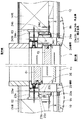
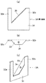
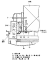
図1は本発明による固定金具を用いて窓枠を取付けた窓の縦断面図、図2は同じく横断面図、図3は固定金具の取付位置の一例を示す窓枠の正面図、図4は固定金具の一つの構成要素である第1金具の展開図であって、(a)は正面図、(b)は平面図、(c)は斜視図、図5は固定金具のもう一つの構成要素である第2金具の展開図であって、(a)は正面図、(b)は平面図、(c)は斜視図である。図6は二つの金具を結合してなる固定金具の正面図、図7は図2の右側の縦枠に取付けられた固定金具の詳細を示す一部拡大断面図である。 FIG. 1 is a longitudinal sectional view of a window to which a window frame is mounted using a fixing metal fitting according to the present invention, FIG. 2 is a horizontal sectional view thereof, and FIG. 3 is a front view of the window frame showing an example of a fixing metal mounting position. FIG. 5 is a development view of the first metal fitting, which is one component of the fixing metal, wherein (a) is a front view, (b) is a plan view, (c) is a perspective view, and FIG. 5 is another figure of the fixing metal. It is an expanded view of the 2nd metal fitting which is a component, Comprising: (a) is a front view, (b) is a top view, (c) is a perspective view. 6 is a front view of a fixing metal fitting formed by joining two metal fittings, and FIG. 7 is a partially enlarged sectional view showing details of the fixing metal fitting attached to the vertical frame on the right side of FIG.
図1及び図2において、1は窓開口枠であり、従来と同様に、まぐさ11と、窓台12と、左右の柱13,14とを矩形に接続して構成されている。また、2は窓枠であり、従来と同様に、上下の横枠21,22と左右の縦枠23,24を従来技術を用いて矩形に接続して構成されている。ただし、本発明に係る窓枠2は、従来品と異なって、建具又は嵌め殺しガラスを保持するための角筒状の基壁21w,22w;23w,24wは有しているが、窓開口枠1の屋外側面に面付けされる面付け壁は有していない。これにより、窓枠を窓開口枠に嵌合した後、屋内外方向に限られた範囲内で移動することが可能にされている。
1 and 2, reference numeral 1 denotes a window opening frame, which is constructed by connecting a lintel 11, a window base 12, and left and
そして、各枠21,22;23,24の外側面、すなわち、窓開口中心と反対側の面には、屋内外方向に隔てた位置で対向する係止縁21a,21b;22a,22b;23a,23b;24a,24bが突設されていて、各対の係止縁と基壁の背面との間に、後述される第1金具3Aの係止部を挿入し得る溝21c,22c,23c,24cが形成されている。係止縁21a,21b,…24a,24bはいずれも同じ肉厚を有している。さらに、一対の係止縁の少なくとも一方の係止縁には各枠の外方向、すなわち、窓枠の開口中心から遠ざかる方向に延長された部分が設けられて、一対の係止縁の外側に後述されるように、固定金具の第1結合部33及び第2結合部36が収容されるに足る空間21d,22d;23d,24dが構成されている。各枠21,22;23,24の窓開口枠1の内周面に対する取付け安定性向上のため、一対の係止縁21a,21b;22a,22b;23a,23b;24a,24bよりも屋内側に係止縁の延長端と等しい距離まで延びる当接縁21e,22e;23e,24eが設けられている。
Then, on the outer surfaces of the
上下の横枠21,22及び左右の縦枠23,24には、前記各対の係止縁21a,21b〜24a,24b及び溝21d,22d;23d,24dを利用して、本発明に係る固定金具3が予め、すなわち、窓枠2を開口枠1に取付ける前に、装着されている。固定金具3は、図3に一例を示すように、少なくとも各枠の長手方向両端部付近に、各枠の長さが長いために後述される固定金具による補強効果が望まれる場合は長手方向両端部付近と中間位置に、備えられる。
The upper and lower
固定金具3は、図4に例示された第1金具3Aと、図5に例示された第2金具3Bとからなっている。第1金具3Aは剛性を有する金属板、例えば鋼板で作られ、本体31の左右両側辺に平行に延在する係止部32a,32bを有し、その間に両係止部を結ぶ平面に対して直角方向片側に延び、かつ、両係止部の平行線に対して一定角度で傾斜する帯状の第1結合部33を有している。一定角度の具体値は任意であるが、図示の例は、両係止部の平行線に対して45度である。
The
第1金具3Aの製造方法は限定されないが、一例を説明すると、矩形の鋼板の一辺の一端部付近からその一辺に直角な方向に反対側の辺までの三分の二程度の距離まで切線を設け、その切線の両端部と一辺の他端部付近とを結ぶ三角形部分を、切線の終点と一辺の他端部付近とを結ぶ直線に沿ってその鋼板に対して直角になるまで折曲げ、その折曲げられた三角形部分を折曲げ部から上記窓枠2の空間21d,22d;23d,24dの深さ、すなわち、各枠の係止縁の延長部分の長さと等しい距離だけ離れた位置で切除して、台形の第1結合部33が形成されている。そして、その第1結合部33のほぼ中央には、その結合部の平面に対して直角方向に貫通された真円のねじ孔又はネジをねじ込むことができる孔(以下には単に孔という。)34が形成されている。
Although the manufacturing method of the 1st metal fitting 3A is not limited, if an example is demonstrated, a cutting line will be carried out to the distance of about 2/3 from the vicinity of one end of one side of a rectangular steel plate to the opposite side in the direction perpendicular to the one side. Provided, bend the triangular part connecting the both ends of the cut line and the vicinity of the other end of one side, along a straight line connecting the end point of the cutting line and the vicinity of the other end of the one side until it is perpendicular to the steel plate, The bent triangular portion is separated from the bent portion by a distance equal to the depth of the
第2金具3Bも同様の金属板、例えば鋼板で作られ、L字形の下辺部で固着部35が構成され、その固着部の左右いずれか一方側からその固着部35に対して第1金具の第1結合部33の角度と等しい角度、図示の例では45度で傾斜する帯状の第2結合部36が構成されている。第2結合部36の幅は、第1金具3Aの第1結合部33の幅と等しくされている。そして、固着部35と第2結合部36の幅方向中央にそれぞれ,ねじを貫通できる長孔37,38が各結合部の長手方向長軸が一致するように形成されている。
The second metal fitting 3B is also made of the same metal plate, for example, a steel plate, and a fixing
第1金具3Aと第2金具3Bは、図6に例示するように、1個のビス4(第2ビスに相当)で結合することができる。すなわち、図4(c)に示されている第1金具3Aの第1結合部33に第2金具3Bの第2結合部36を重なり合わせ、第1結合部33の孔34と第2結合部36の長孔38とを合致させて、長孔38からビス4を挿通し、孔34に適当量ねじ込むことにより、第1金具3Aと第2金具3Bが結合される。この場合、第1金具3Aの本体31と第2金具3Bの固着部35との間には、窓枠WFの係止縁21a,21b〜24a,24bの肉厚よりも0.05〜0.10mm程度狭い隙間が形成されるように構成されている。また、ビス4のねじ込み量を小さくすることにより、第1結合部33と第2結合部36を長孔38の長軸方向及びその長軸に対して直角方向に相対移動することができ、従って、第1金具3Aと第2金具3Bは、図6において左右方向(窓枠の屋内外方向に相当)と上下方向(窓枠の高さ方向又は左右方向に相当)に相対移動が可能である。
The first metal fitting 3A and the second metal fitting 3B can be coupled with one screw 4 (corresponding to the second screw) as illustrated in FIG. That is, the
図4ないし図6に示されている固定金具3は、図2の右側の縦枠24(図7の縦枠24)、すなわち、屋外側から見た窓枠WFを示す図3の右側の縦枠24に取付けられるものの形状を示しているが、図3の左側の縦枠23に取付けられる固定金具3Eは、右側の縦枠24に取付けられる固定金具3と左右対称形に作られ、また、図3の上下の横枠21,22に取付けられる固定金具3´,3´Eは、図4,5に示された右縦枠用固定金具3を左90度又は右90度に反転した形で用いられる。
4 to 6 is a
上記形態を有する固定金具の窓枠に対する装着方法を、図2の右側の固定金具の場合について、すなわち、屋外側から見た窓枠WFを示す図3の右側の縦枠に取付けられたものについて、図7を用いて説明する。
矩形に枠組みされた窓枠においては、縦枠24の溝24cが縦枠の上下端面で開放されているので、その溝の上下いずれか一方又は両方の端部から第1金具3Aを挿入し、各端部から所定距離まで移動した後、溝24cから外に突出している第1結合部33の上面に第2金具3Bの第2結合部36を重ね合わせ、長孔38に貫通したビス4を孔33に緩くねじ込むことにより、その縦枠の一対の係止縁24a,24bを、第1金具3Aの係止部32a,32bと第2金具3Bの第2結合部36とで挟持した状態で仮固定する。
As for the mounting method of the fixing bracket having the above-described form with respect to the window bracket on the right side of FIG. 2, that is, attached to the right vertical frame of FIG. 3 showing the window frame WF viewed from the outdoor side. This will be described with reference to FIG.
In the rectangular window frame, the
一方、上下の横枠21,22の溝21c,22cは、縦枠23,24の基壁により遮蔽されているので、第1金具3Aをその溝に挿通することができない。そこで、横枠の係止縁21a,21b;22a,22bを横枠の長手方向任意の位置において切除して切欠(不図示)が形成され、その切欠から第1金具の一対の係止部32a,32bを溝21c,22cに挿入して、その第1金具3Aを横枠の長手方向端部から所定位置まで移動した後、縦枠の場合と同様に、その第1金具3Aに第2金具3Bをビス4で仮結合し、かつ、横枠21,22に仮固定する。
On the other hand, since the
固定金具3,3E;3´,3´Eの窓枠に対する装着方法は、上記のように枠組み後に各枠に取付ける方法のほか、枠組み前に各枠に取付けることも可能である。この場合は、横枠の係止縁に切欠を設ける必要がないことはいうまでもない。
The fixing
続いて、各枠に複数個ずつの固定金具3,3E;3´,3´Eを装着した窓枠2を、その固定金具を用いて窓開口枠1に固定する方法について、主として図7を参照しながら説明する。
まず、窓枠2を窓開口枠1の中に嵌合し、各固定金具の第2金具3Bの固着部35を窓開口枠1の屋外側面、すなわち、縦枠23,24の固定金具3E,3においては柱13,14、上枠11の固定金具3´,3´Eにおいてはまぐさ11、下枠2の固定金具3´,3´Eにおいては窓台12のそれぞれの屋外側面に当接して窓枠を安定させた状態で、窓枠を左右方向及び上下方向に移動して窓枠の窓開口枠に対する位置決めを行う。この場合の位置決めは精密でなくても良い。そして、非精密位置決めをした状態で、各固定金具の第2金具3Bの固着部35の長孔37から木ねじ5(第1ネジに相当)を窓開口枠1(柱、まぐさ、窓台)にねじ込んで、それぞれの第2金具3Bを窓開口枠1に仮固定する。
Subsequently, a method of fixing the
First, the
次に、窓枠2を左右及び上下方向に僅かに移動して、下枠22が完全な水平になり、縦枠23,24が完全な垂直になるように水平及び垂直のレベル調整を行う。この場合、各固定金具の木ねじ5は第2金具3Bの長孔37に対してはその長軸方向及びこれと直角な方向に摺動可能であり、上下の横枠21,22の固定金具における第2金具の固着部35の長孔37は長軸が垂直になっているので、窓枠の位置調整が可能であり、そのとき、第2金具の固着部35が長孔37の範囲内で木ねじ5に対して移動する。このレベル調整により窓枠の左右方向及び上下方向の位置決めが適正化された後、各固定金具の固着部における木ねじを完全に締める。
Next, the
次に、窓台12の上面と下枠22との間に楔状のスペーサ61 を差し込んで下枠22の窓台12に対する高さを固定する。
Next, a wedge-shaped
続いて、窓枠2の少なくとも4コーナー部、すなわち、縦枠と横枠の接続部付近において窓枠に屋内外方向の力を加えて、窓枠の屋内外方向位置を調整する。そのとき、各固定金具のビス4は第2金具3Bの第2結合部36の長孔38に対してはその長軸方向及びこれと直角な方向に摺動可能であるので、第2結合部36の長孔38の範囲内で屋内外方向の任意の位置まで調整可能である。この調整の際に、各固定金具における第2金具3Bから離間した第1金具3Aを、その第1結合部33が第2金具の第2結合部36に当接するまで縦枠の溝23c,24c又は横枠の溝21c,22cに沿って移動した後、各枠の屋外側の係止縁21a,22a,23a,24aと開口枠の内周面との間で屋外側に開放されている隙間からねじ回し工具(ドライバ)のビットを挿入し、ビス4を完全に締めて第1金具3Aと第2金具3Bを本結合し、かつ、各枠21〜24を窓開口枠1に固定する。
Subsequently, the indoor / outdoor direction position of the window frame is adjusted by applying a force in the indoor / outdoor direction to at least the four corners of the
その後、各縦枠23,24と柱13,14の間及び上枠21とまぐさ11の間に、各枠の木ねじ貫通位置を含む領域において、下部スペーサ61 と同様のスペーサ62 ,63 ,64 を差し込んで、各枠の位置を固定する。この場合のスペーサ61 〜64 は、従来品のように位置調整機能と固定機能を果たすのではなく、固定金具により取付け位置を調整された窓枠を単にその位置に固定するだけの機能を果たす。
Thereafter, spacers 62, 63, 64 similar to the
最後に、各枠21〜24の基壁の内周面の屋内側寄りの位置であってスペーサ61 〜64 に対応する所定位置から第3ビスに相当する木ねじ7をスペーサ61 〜64 に貫通し、窓開口枠1までねじ込んで、窓枠2を完全に窓開口枠1に固定する。
Finally, wood screws 7 corresponding to the third screws are passed through the
図1,2及び図7において、8は、窓枠固定後に各固定金具の第2金具の固着部35をその屋外側面において被覆するように、まぐさ11、窓台12及び柱13,14の屋外側面から各枠の基壁の外側面まで延長させて貼付けられた防水シートであり、9a,9bは、各枠の屋外側端面から建物の外装材10まで延在する幅を備えた額縁であり、背面に備えた一対の係止縁の弾性的嵌着により取付けが容易にできるようにしてあり、窓枠の装飾性向上と、外装材見切りの収容による防水性向上の機能を併有している。
In FIGS. 1, 2 and 7,
固定金具の第1金具3Aを窓枠の各枠の外側部分に摺動自在に備えるには、上述された一対の係止縁により溝を形成し、これに両端の係止部を挿入して係止する構造に限らず、各枠の長手方向に摺動自在に各枠に保持することができる任意の形状で実現することができる。また、固定金具の第1結合部と第2結合部の傾斜角度は、調整のための移動量を最小限にするため45度が最も好ましいが、両者等しい角度であれば、45度以外の任意の角度でも良い。また、ビスが先に挿入される結合部に長孔が設けられ、ビスが最後にねじ込まれる孔が真円であれば、第1金具の結合部と第2金具の結合部の重なり合う位置関係はとくに制限されない。また、第1金具及び第2金具の形状、各枠に対する装着形態が対称形か否かはとくに制限されない。 In order to slidably provide the first metal fitting 3A of the fixing metal on the outer part of each frame of the window frame, a groove is formed by the above-mentioned pair of locking edges, and the locking portions at both ends are inserted into this. Not only the structure to be locked but also any shape that can be slidably held in each frame in the longitudinal direction of each frame. The inclination angle of the first coupling portion and the second coupling portion of the fixing bracket is most preferably 45 degrees in order to minimize the amount of movement for adjustment. Any angle is acceptable. In addition, if a long hole is provided in the coupling portion into which the screw is inserted first and the hole into which the screw is screwed last is a perfect circle, the overlapping positional relationship between the coupling portion of the first metal fitting and the coupling portion of the second metal fitting is There is no particular restriction. Moreover, it is not restrict | limited in particular whether the shape of the 1st metal fitting and the 2nd metal fitting and the mounting form with respect to each frame are symmetrical.
本発明は、金属製、樹脂製のいずれを問わず、型材を組んで構成される窓枠を窓開口枠に嵌合し、その窓開口枠の屋外側面の所定の位置に固定する場合に適用可能である。 The present invention is applied to a case where a window frame formed by assembling a mold material is fitted to a window opening frame and fixed to a predetermined position on the outdoor side surface of the window opening frame regardless of whether it is made of metal or resin. Is possible.
また、図面には、引違い戸d1,d2及び網戸d3が建て付けられている窓枠2が示されているが、本発明は、建具のない嵌め殺しガラスを保持する窓枠にも同様に適用可能である。
Moreover, although the
1 窓開口枠
11 まぐさ
12 窓台
13,14 柱
2 窓枠
21,22 上下の横枠
23,24 左右の縦枠
3,3E;3´,3´E 固定金具
3A 第1金具
31 本体
32a,32b 係止部
33 第1結合部
34 孔
3B 第2金具
35 固着部
36 第2結合部
37,38 長孔
4 ビス(第2ネジ)
5 木ねじ(第1ネジ)
6 スペーサ
7 木ねじ
DESCRIPTION OF SYMBOLS 1 Window opening frame 11 Pillar 12 Window stand 13,14
5 Wood screw (1st screw)
6 Spacer 7 Wood screw
Claims (3)
第1金具は、両端部に、窓枠の横枠と縦枠の外側部分に各枠の長手方向に摺動自在に係止される係止部を有するとともに、両係止部の間に屈曲形成され、その係止部から各枠の長手方向に対して一定角度の傾斜面に沿って窓開口中心から遠ざかる方向に延出する第1結合部とを有し、
第2金具は、前記窓開口枠の屋外側面に第1ネジで固着される固着部と、その固着部から各枠の長手方向に対して一定角度の傾斜面に沿って屋内方向に延出して前記第1結合部に重ね合わせることができる第2結合部とを有し、
第1結合部と第2結合部の一方には長孔が、他方にはその長孔に挿通した第2ネジをねじ込み得る孔がそれぞれ設けてあり、
前記両係止部が窓枠の縦枠又は横枠の外側面に形成された一対の係止縁で形成された溝に摺動自在に挿入され、前記縦枠又は横枠の係止縁を第1金具の両係止部と第1金具の第1結合部に第2ネジで仮結合された第2金具の第2結合部との間に挟持することにより窓枠に装着されることを特徴とするサッシ窓枠用固定金具。 Each consists of a first metal fitting and a second metal fitting made by cutting and bending a steel plate ,
The first metal fitting has a locking portion that is slidably locked in the longitudinal direction of each frame at both ends of the horizontal frame and the vertical frame of the window frame, and bends between both locking portions. A first coupling portion formed from the locking portion and extending in a direction away from the window opening center along an inclined surface having a constant angle with respect to the longitudinal direction of each frame;
The second metal fitting is fixed to the outdoor side surface of the window opening frame with a first screw, and extends from the fixed portion to the indoor direction along an inclined surface having a fixed angle with respect to the longitudinal direction of each frame. A second coupling part that can be superimposed on the first coupling part,
One of the first coupling part and the second coupling part is provided with a long hole, and the other is provided with a hole into which a second screw inserted through the long hole can be screwed.
The both locking portions are slidably inserted into a groove formed by a pair of locking edges formed on the outer surface of the vertical frame or horizontal frame of the window frame, and the locking edges of the vertical frame or horizontal frame are It is attached to the window frame by being sandwiched between both locking portions of the first metal fitting and the second joint portion of the second metal fitting temporarily joined to the first joint portion of the first metal fitting with the second screw. A fixing bracket for sash window frames.
(b)前記窓枠を窓開口枠の中に嵌合し、各固定金具の第2金具の固着部を前記窓開口枠の屋外側面に当接して、その窓枠の左右方向及び上下方向の位置調整をした後、各固着部の長孔に貫通した第1ネジを前記窓開口枠の屋外側面にねじ込んで固着し、
(c)前記窓枠を少なくとも各固定金具の装着位置において屋内外方向に移動して位置調整をするとともに、第2ネジを完全に締めて第1金具と第2金具を堅固に結合すると同時に前記窓枠の左右方向、上下方向及び屋内外方向の位置を固定することを特徴とするサッシ窓枠の固定方法。 (A) The sash window frame fixing bracket according to claim 2 is provided at least in the vicinity of both longitudinal ends of the vertical frame and horizontal frame of the window frame, and the locking edges of the vertical frame and horizontal frame of the window frame Is attached between both the locking portion of the first metal fitting and the second coupling portion of the second metal fitting temporarily joined to the first coupling portion of the first metal fitting with the second screw,
(B) The window frame is fitted into the window opening frame, the fixing portion of the second metal fitting of each fixing bracket is brought into contact with the outdoor side surface of the window opening frame, and the left and right and vertical directions of the window frame are After adjusting the position, the first screw that penetrates the long hole of each fixing portion is screwed and fixed to the outdoor side surface of the window opening frame,
(C) The window frame is moved indoors / outdoors at least at the mounting positions of the respective fixing brackets and adjusted, and the second screw is completely tightened to firmly join the first bracket and the second bracket at the same time. A method for fixing a sash window frame, comprising fixing the positions of the window frame in the horizontal direction, vertical direction, and indoor / outdoor direction.
Priority Applications (1)
| Application Number | Priority Date | Filing Date | Title |
|---|---|---|---|
| JP2003275260A JP4056950B2 (en) | 2003-07-16 | 2003-07-16 | Sash window frame fixing bracket and fixing method |
Applications Claiming Priority (1)
| Application Number | Priority Date | Filing Date | Title |
|---|---|---|---|
| JP2003275260A JP4056950B2 (en) | 2003-07-16 | 2003-07-16 | Sash window frame fixing bracket and fixing method |
Publications (2)
| Publication Number | Publication Date |
|---|---|
| JP2005036533A JP2005036533A (en) | 2005-02-10 |
| JP4056950B2 true JP4056950B2 (en) | 2008-03-05 |
Family
ID=34211967
Family Applications (1)
| Application Number | Title | Priority Date | Filing Date |
|---|---|---|---|
| JP2003275260A Expired - Fee Related JP4056950B2 (en) | 2003-07-16 | 2003-07-16 | Sash window frame fixing bracket and fixing method |
Country Status (1)
| Country | Link |
|---|---|
| JP (1) | JP4056950B2 (en) |
Families Citing this family (1)
| Publication number | Priority date | Publication date | Assignee | Title |
|---|---|---|---|---|
| JP5904572B2 (en) * | 2011-06-16 | 2016-04-13 | 株式会社Lixil | Installation structure of opening device |
-
2003
- 2003-07-16 JP JP2003275260A patent/JP4056950B2/en not_active Expired - Fee Related
Also Published As
| Publication number | Publication date |
|---|---|
| JP2005036533A (en) | 2005-02-10 |
Similar Documents
| Publication | Publication Date | Title |
|---|---|---|
| US20100043268A1 (en) | Relating to picture frames | |
| US9487956B2 (en) | Cladding assembly | |
| US10202761B2 (en) | Curtain wall system, corner bracket for curtain wall system, and associated method | |
| JP2016191249A (en) | Attaching support jig for outer wall member and construction method thereof | |
| AU2018232364B2 (en) | Wall-material mounting member and wall structure | |
| US9945131B2 (en) | Slidable snap-in trim system | |
| JP4056950B2 (en) | Sash window frame fixing bracket and fixing method | |
| KR20160072656A (en) | Corner bracket assembly for windows | |
| JP5109609B2 (en) | Glass plate connection structure in panel system and panel body used therefor | |
| JPH0913798A (en) | Fitting device for sash | |
| US20070175123A1 (en) | Trim system for doors and windows with corner block assembly | |
| JPS6349496Y2 (en) | ||
| JPS6135671Y2 (en) | ||
| JP2011099281A (en) | Lattice panel | |
| JP4199652B2 (en) | Unit room wall panel connection structure | |
| JP7257886B2 (en) | fittings and shoji | |
| JPH037499Y2 (en) | ||
| JP6211728B2 (en) | Bracing joint plate and bracing unit using the same | |
| JP6700760B2 (en) | Exterior wall exterior corner structure and exterior corner base material | |
| CN211341611U (en) | External corner fixing piece | |
| JP2015190140A (en) | Frame body and fitting structure therefor | |
| JP2004232396A (en) | Fitting hardware for external facing material, fitting structure and construction method using the same | |
| JP4413683B2 (en) | Member positioning tool | |
| JP7045132B2 (en) | Board fixtures and board construction methods | |
| CA2533057A1 (en) | Trim system for doors and windows with corner block assembly |
Legal Events
| Date | Code | Title | Description |
|---|---|---|---|
| A621 | Written request for application examination |
Free format text: JAPANESE INTERMEDIATE CODE: A621 Effective date: 20060206 |
|
| A977 | Report on retrieval |
Free format text: JAPANESE INTERMEDIATE CODE: A971007 Effective date: 20070823 |
|
| A131 | Notification of reasons for refusal |
Free format text: JAPANESE INTERMEDIATE CODE: A131 Effective date: 20070904 |
|
| A521 | Written amendment |
Free format text: JAPANESE INTERMEDIATE CODE: A523 Effective date: 20071102 |
|
| TRDD | Decision of grant or rejection written | ||
| A01 | Written decision to grant a patent or to grant a registration (utility model) |
Free format text: JAPANESE INTERMEDIATE CODE: A01 Effective date: 20071211 |
|
| A61 | First payment of annual fees (during grant procedure) |
Free format text: JAPANESE INTERMEDIATE CODE: A61 Effective date: 20071212 |
|
| R150 | Certificate of patent or registration of utility model |
Free format text: JAPANESE INTERMEDIATE CODE: R150 |
|
| FPAY | Renewal fee payment (event date is renewal date of database) |
Free format text: PAYMENT UNTIL: 20101221 Year of fee payment: 3 |
|
| FPAY | Renewal fee payment (event date is renewal date of database) |
Free format text: PAYMENT UNTIL: 20101221 Year of fee payment: 3 |
|
| FPAY | Renewal fee payment (event date is renewal date of database) |
Free format text: PAYMENT UNTIL: 20111221 Year of fee payment: 4 |
|
| LAPS | Cancellation because of no payment of annual fees |