JP4056624B2 - Disposable processing equipment - Google Patents
Disposable processing equipment Download PDFInfo
- Publication number
- JP4056624B2 JP4056624B2 JP13325798A JP13325798A JP4056624B2 JP 4056624 B2 JP4056624 B2 JP 4056624B2 JP 13325798 A JP13325798 A JP 13325798A JP 13325798 A JP13325798 A JP 13325798A JP 4056624 B2 JP4056624 B2 JP 4056624B2
- Authority
- JP
- Japan
- Prior art keywords
- chamber
- processing chamber
- chambers
- array
- cover
- Prior art date
- Legal status (The legal status is an assumption and is not a legal conclusion. Google has not performed a legal analysis and makes no representation as to the accuracy of the status listed.)
- Expired - Lifetime
Links
Images


Classifications
-
- B—PERFORMING OPERATIONS; TRANSPORTING
- B01—PHYSICAL OR CHEMICAL PROCESSES OR APPARATUS IN GENERAL
- B01L—CHEMICAL OR PHYSICAL LABORATORY APPARATUS FOR GENERAL USE
- B01L3/00—Containers or dishes for laboratory use, e.g. laboratory glassware; Droppers
- B01L3/50—Containers for the purpose of retaining a material to be analysed, e.g. test tubes
- B01L3/508—Containers for the purpose of retaining a material to be analysed, e.g. test tubes rigid containers not provided for above
-
- B—PERFORMING OPERATIONS; TRANSPORTING
- B01—PHYSICAL OR CHEMICAL PROCESSES OR APPARATUS IN GENERAL
- B01L—CHEMICAL OR PHYSICAL LABORATORY APPARATUS FOR GENERAL USE
- B01L9/00—Supporting devices; Holding devices
- B01L9/06—Test-tube stands; Test-tube holders
-
- Y—GENERAL TAGGING OF NEW TECHNOLOGICAL DEVELOPMENTS; GENERAL TAGGING OF CROSS-SECTIONAL TECHNOLOGIES SPANNING OVER SEVERAL SECTIONS OF THE IPC; TECHNICAL SUBJECTS COVERED BY FORMER USPC CROSS-REFERENCE ART COLLECTIONS [XRACs] AND DIGESTS
- Y10—TECHNICAL SUBJECTS COVERED BY FORMER USPC
- Y10T—TECHNICAL SUBJECTS COVERED BY FORMER US CLASSIFICATION
- Y10T436/00—Chemistry: analytical and immunological testing
- Y10T436/25—Chemistry: analytical and immunological testing including sample preparation
- Y10T436/2575—Volumetric liquid transfer
Abstract
Description
【0001】
【発明の属する技術分野】
本発明は生物学的試料が一つまたはそれ以上の試薬で処理される方法を実行するための使い捨て装置に関する。
本発明は、特に、生物学的試料から精製された核酸試料を得るための方法を実行するために好適であるこの種類の使い捨て装置に関する。
本発明は、さらに、精製された核酸試料を得るために生物学的流体試料を一つまたはそれ以上の試薬で処理するためのこのような装置の使用法に関する。
【0002】
【従来の技術および発明が解決しようとする課題】
例えば、ポリメラーゼ連鎖反応(PCR)により増幅されることが好適である精製された核酸試料を得るための既知の方法は、通常、手動で実行されかついくつかの工程、特に複数のピペット操作による液体の移送を含む。得られるべき試料の汚染を可能な限り減らさなければならないので、この手動方法は、極めて十分な注意を払って実施しなければならず、それゆえに、時間のかかる作業である。
【0003】
分析装置においてピペット操作で液体を移す作業を自動的に実施するための既知の装置は、例えば、ポリメラーゼ連鎖反応(PCR)により増幅されることが好適である精製された核酸試料を得ることを目的とする方法として不十分であることが判明した。そのわけは、ピペット操作により液体を移す間に、試料の汚染が発生しがちであるからである。
【0004】
【課題を解決するための手段】
それゆえに、本発明の主な目的は、高度の純度を有しかつそれにより、例えば、ポリメラーゼ連鎖反応(PCR)により増幅されることが適当である核酸試料を提供する核酸精製方法の要求条件に十分に応ずる程度に試料および試薬の汚染を生じないような自動処理を行うために案出された序文に簡単に述べた型式の装置を提供することにある。
【0005】
本発明の第1局面によれば、この問題は、使い捨て処理装置が
a)一体に構成された室の配列、一体に構成されたカバーインサートおよび使い捨てピペットチップを備え、
b)前記の一体に構成された室の配列が
b.1)細長いトレーとして形成されかつ底壁部と該底壁部の周囲に対して垂直にかつ該周囲に沿って延在する側壁部とにより境界が定められた内側部を有する上側部分と、
b.2)前記上側部分の底壁部に対して実質的に垂直にかつ前記底壁部の第1開口から下方に延在する管状壁部により連結された開口した上端部および閉ざされた底端部を有する第1処理室とを備え、前記第1開口は第1処理室の開口した上端部を形成し、さらに、
b.3)廃液を受け入れるための廃液室を備え、前記廃液室は前記上側部分の底壁部に対して実質的に垂直にかつ前記底壁部の第2開口から下方に延在する側壁部により連結された開口した上端部および閉ざされた底端部を有し、前記第2開口は廃液室の開口した上端部を形成し、
c)前記の一体に構成されたカバーインサートは該室の配列内に挿入されるような形状と寸法を有しかつ前記カバーインサートは
c.1)前記カバーインサートが前記室の配列内に挿入されたときに処理室および廃液室にそれぞれアクセスするための開口を有する細長いカバーと、
c.2)内部に前記の使い捨てピペットチップを収容するための収容室とを備え、前記収容室はカバーに対して実質的に垂直にかつカバーの開口から下方に延在する管状壁部により連結された開口した上端部および閉ざされた底端部を有し、
d)前記使い捨てピペットチップは収容室の内部に少なくとも部分的に挿入されるように形成されつ寸法を有することを特徴とする使い捨て処理装置により解決される。
【0006】
本発明の第2局面によれば、上記の目的は、生物学的流体試料が一つまたはそれ以上の試薬で処理される方法を実施するための本発明による装置を使用することにより達成される。この方法は、処理室から廃液室への液体の自動移送、または該装置の外側の一次試料管から第1処理室への液体の自動移送、または処理室から該装置の外側の試験体容器への液体の自動移送の工程を含み、かつ前記液体の移送が該装置の一部である使い捨てピペットチップを専用して実施されるピペット操作により行われる。
【0007】
本発明による装置および方法の主な利点は、前記装置および方法により、高度の純度を有しかつそれにより例えばポリメラーゼ連鎖反応(PCR)により増幅されることが好適である核酸試料を提供する核酸精製方法の要求条件に十分に応ずる程度に試料および試薬の汚染を生じない自動処理を確保することが可能であることにある。
【0008】
本発明による装置のさらに一つの利点は、それぞれの生物学的試料から対応した複数の精製された核酸試料を得るために自動装置内で複数のこれらの装置を同時に使用することができることにある。
【0009】
一つの処理室のみを備えている本発明による装置の一実施例の特定の利点は、一つ以上の処理室を備えている装置よりも安価でありかつ該装置のサイズが小さいことにより、装置の使用後に廃棄することが必要な廃棄材料が少なくなり、かつ廃棄材料ののための包装材料のコストが低減することにある。
【0010】
本発明による装置の好ましい一実施例は、カバーが液体を処理室の中に分与するために処理室の内部にアクセスするための第1チャネルを備え、この分与が使い捨てピペットチップとは別のピペット操作カニューレにより行われることを特徴としている。この実施例の利点は、上記のみぞがピペット操作の間にピペット操作カニューレのチップが実質的に閉ざされた環境の内部に配置されることを保証し、それによりピペット操作カニューレからの液体を処理室に移す間に不測の汚染の発生を阻止することにある。
【0011】
本発明による装置のさらに好ましい一実施例は、前記カバーインサートが前記の室の配列の中に挿入されたときに、収容室の実質的な部分が廃液室の内部に配置されることを特徴としている。この構成により、収容室のために付加的なスペースが必要でないので、この装置により占有されるスペースが有利に減少される。
【0012】
本発明による装置の別の好ましい実施例は、処理室が室の配列の前記上側部分の底壁部から下方に自由に垂下していることを特徴としている。この構成により、処理室の下側部分が外部の装置、例えば、処理室内に収容された液体内の浮遊物中の磁気粒子の分離を可能にするために使用される磁石による影響をうけやすいという利点が得られる。
【0013】
本発明による装置のさらに好ましい一実施例は、前記の一体に構成された室の配列がさらに前記上側部分の底壁部に対して実質的に垂直にかつ前記底壁部の第3開口から下方に延在する管状壁部により連結された開口した上端部および閉ざされた底端部を有する第2処理室を備え、前記第3開口が第2処理室の開口した上端部を形成していることを特徴としている。この実施例の利点は、該実施例により、特定の方法を実施するための処理工程のシーケンスに関してより大きい融通性が得られることにある。この融通性は、例えば、処理室を異なる温度に維持し、例えば、処理室の一方を60℃に維持しかつ他方を37℃に維持しかつ/または処理室の一方を試薬が他方の処理室に移送される前に試薬の仮の貯蔵のために使用することにより増大される。
【0014】
2つの処理室を備えている本発明による装置の好ましい一実施例は、前記上側部分の底壁部が液体を第2処理室の中に分与するために第2処理室の内部にアクセスするための第2チャネルを備え、この分与が使い捨てピペットチップとは別のピペット操作カニューレにより行われることを特徴としている。この実施例の利点は、第2みぞがピペット操作の間にピペット操作カニューレのチップが実質的に閉ざされた環境の内部に配置されることを保証し、それにより液体をピペット操作カニューレから第2処理室に移送する間に不測の汚染の発生を阻止することにある。
【0015】
2つの処理室を備えている本発明による装置の別の好ましい実施例は、第1処理室、廃液室および第2処理室が一列に配置されていることを特徴としている。この構成は、自動処理装置における本発明による複数の装置の配列ならびに使い捨てピペットチップおよびピペット操作カニューレを該装置の種々の室に関するそれらのピペット操作位置に移動すために使用される運搬装置を有利に簡素化している。
【0016】
2つの処理室を備えている本発明による別の好ましい実施例は、廃液室が第1処理室と第2処理室との間に配置されていることを特徴としている。この構成により、使い捨てピペットチップおよびピペット操作カニューレを該装置の種々の位置に関するそれらのピペット操作位置に移動するために必要なこれらの部材の移動通路を有利に減少している。
【0017】
2つの処理室を備えている本発明による装置のさらに好ましい一実施例は。第2処理室が室の配列の前記上側部分の底壁部から下方に自由に垂下していることを特徴としている。この構成により、第2処理室の下側部分が外部の装置、例えば、第2処理室内に収容された液体内の浮遊物中の磁気粒子の分離を可能にするために使用される磁石の影響をうけやすいという利点が得られる。
【0018】
本発明による装置の好ましい実施例は、本発明による装置の室の配列がプラスチック材料で一体に構成されていることを特徴としている。
【0019】
本発明による装置の好ましい実施例は、本発明による装置の前記カバーインサートがプラスチック材料で一体に構成されていることを特徴としている。
これらの好ましい実施例においては、この装置の製造コストを低減することが可能である。
【0020】
本発明による装置の好ましい使用法は、該装置の外側の試薬容器からの液体試薬を処理室の中に分与する工程を含み、前記分与が該装置の一部である使い捨てピペットチップのほかのピペット操作カニューレにより行われることを特徴とする方法を実施するためである。
【0021】
2つの処理室を備えている本発明による装置の好ましい使用法は、この方法が第1処理室から第2処理室への液体の自動移送、またはその逆の液体の自動移送、または第1処理室または第2処理室から廃液室への液体の自動移送、または該装置の外部の一次試料管から第1処理室または第2処理室への液体の自動移送、または第1処理室または第2処理室から該装置の外部の試験体容器への液体の自動移送の工程を含み、かつ前記の液体の移送が該装置の一部である使い捨てピペットチップを専用して実施されるピペット操作により行われることを特徴とする方法を実施するためである。
【0022】
2つの処理室を備えている本発明による装置のさらに好ましい使用法は、この方法が該装置の外側の試薬容器からの液体試薬を第1処理室および/または第2処理室中に分配する工程を含み、前記分配が該装置の部分である使い捨てピペットチップのほかのピペット操作カニューレにより行われることを特徴とする方法を実施するためである。
【0023】
本発明による装置の好ましい使用法は、生物学的試料内に収容された核酸を分離する方法を実施するためである。
【0024】
【発明の実施の形態】
本発明の好ましい実施例を添付図面を参照して以下に説明する。
図1から図3は、本発明による装置11の第1実施例を示す。この第1実施例は、一体に構成された室19の配列、一体に構成されたカバーインサート12および使い捨てピペットチップ18を備えている。室19の配列およびカバーインサート12は、カバーインサート12を室19の配列の上側部分の中に挿入することにより一緒に組み立てられる。図1および図2は、この組立体を示す。
【0025】
室19の配列は、
−細長いトレーとして形成されかつ底壁部39と該底壁部の周囲に対して垂直にかつ該周囲に沿って延在する側壁部38とにより境界が設定された内側部を有する上側部分と、
−処理室26と、
ー廃液を受け入れるための廃液室25とを備えている。
【0026】
処理室26は、室19の配列の上側部分の底壁部39に対して実質的に垂直にかつ底壁部39の第1開口から下方に延在する管状壁部16により連結された開口した上端部および閉ざされた底端部を有する。この第1開口は、第1処理室26の開口した上端部を形成している。処理室26は、室19の配列の上側部分の底壁部39から下方に自由に垂下している。
【0027】
廃液室25は、室19の配列の上側部分の底壁部39に対して実質的に垂直にかつ底壁部39の第2開口から下方に延在する側壁部15により連結された開口した上端部および閉ざされた底端部を有する。この第2開口は、廃液室25の開口した上端部を形成している。
【0028】
カバーインサート12は、室19の配列内に挿入されるような形状および寸法を有する。カバーインサート12は、
−該カバーインサートが室19の配列内に挿入されるときに、処理室26および廃液室25にそれぞれアクセスするための開口36および35を有する細長いカバー13と、
−内部に使い捨てピペットチップ18を収容するための収容室24とを備えている。
【0029】
好ましい一実施例においては、カバー13が噴流そらせ板23を含む。噴流そらせ板23は、特に図2に示した位置を有しかつ廃液室25の中にピペットで移される液体の噴流をそらせる役目をする。噴流そらせ板23は、このような噴流が廃液室25内に既に収容された液体の自由平面上に直接に衝突することを阻止する。このような衝突は、ある場合には、噴流が液体のはね返りをひき起こしかつ若干の量の液滴を廃液室25外に開口35を通じて排出することがあり得るので、望ましくない。
【0030】
収容室24は、カバー13に対して実質的に垂直にかつカバー13の開口34から下方に延在する管状壁部14により連結された開口した上端部および閉ざされた底端部を有する。好ましい一実施例においては、収容室24の管状壁部14の上端部は、カバー13の上方に配置されている。
【0031】
使い捨てピペットチップ18は、収容室24の内部に少なくとも部分的に挿入されるような形状および寸法に形成されている。使い捨てピペットチップ18は、収容室24の内部に緊密に嵌合する管状壁部を有する。しかしながら、ピペットチップの下端部は、収容室24の底部および側壁部から所定距離に保たれている。
【0032】
使い捨てピペットチップ18の上側部分は、自動装置(図示せず)のピペットチップ運搬装置の部分である好適なピペットチップ掴み具(図示せず)により掴みかつ保持することができるように形成されかつ寸法を有し、それによりピペットチップ18をピペットチップ掴み具によりこの装置の内部の異なるピペット位置に移動することができる。ピペットチップ掴み具は、ピペットチップ18を掴むときに、該掴み具がこのピペットチップ18を自動装置内に収容された計量供給ピペッター(dosing pipettor)(図示せず)と流体で接続することが好ましい。
【0033】
図2に示した好ましい実施例においては、フィルタ31がピペットチップ18の上側部分の内部に配置されている。フィルタ31は、ピペットで液体を移す操作の間に、ガスまたは液体のキャリオーバー(carry−over)による汚染を阻止する役目をする。
【0034】
図1から図3に示した好ましい実施例においては、ピペットチップ18は、該ピペットチップの下側部分が開口35を通じて廃液室25の中に挿入されるときに、該ピペットチップもまた廃液室25の閉鎖部分として使用できるように形成されかつ寸法を有している。
【0035】
カバーインサート12の形状は、自動装置(図示せず)の運搬装置の部分である好適な掴み具(図示せず)により掴みかつ保持することができ、それによりカバーインサート12を、それにより装置11全体を掴み具により、例えば、装置11の配列が並んで配置された収容位置から装置の内部の異なる位置、すなわち、培養器(incubator)の位置に移動することができる。
【0036】
図1から図3に示した好ましい実施例においては、カバーインサート12が図示したように配置された4つの突起部(tangs)21、22、28、29の配列を有する。
【0037】
好ましい一実施例においては、突起部のこの配列の形状および寸法ならびに使い捨てピペットチップ18の上側部分の形状および寸法は、ピペットチップ18の頂部または1対の突起部、例えば、21および22または28および29を同じ掴み具により掴むことができるように選択される。
【0038】
カバー13は、装置11の外側に配置された試薬容器からの試薬を第1処理室26の中にピペットで移すために第1処理室26の内部に接近するための第1チャネル32を有する。このピペットで試薬を移す操作は、使い捨てピペットチップ18とは別のピペット操作カニューレ(図示せず)により行われる。
図1および図2に示すように、カバーインサート12が室19の配列中に挿入されるときに、収容室24の実質的な部分が廃液室25の内部に配置される。
【0039】
図4から図6は、本発明による装置41の第2実施例を示す。この第2実施例は、一体に構成された室49の配列、一体に構成されたカバーインサート42および使い捨てピペットチップ48を備えている。室49の配列およびカバーインサート42は、カバーインサート42を室49の配列の上側部分の中に挿入することにより一緒に組み立てられる。図4および図5はこの組立体を示す。
【0040】
室49の配列は、
−細長いトレーとして形成されかつ底壁部69の周囲に対して垂直にかつ該周囲に沿って延在する側壁部68と底壁部69とにより境界が定められた内側部を有する上側部分と、
−第1処理室56と、
−第2処理室57と、
−廃液を受け入れるための廃液室55とを備えている。
【0041】
処理室56は、室49の配列の上側部分の底壁部69に対して実質的に垂直にかつ底壁部69の第1開口部66から下方に延在する管状壁部46により連結された開口した上端部および閉ざされた底端部を有する。この第1開口66は、第1処理室56の開口した上端部を形成している。
【0042】
処理室57は、室49の配列の上側部分の底壁部69に対して実質的に垂直にかつ底壁部69の第1開口から下方に延在する管状壁部46により連結された開口した上端部および閉ざされた底端部とを有する。この第1開口は、処理室57の開口した上端部を形成している。
処理室56および処理室57は、室49の配列の上側部分の底壁部69から下方に自由に垂下している。
【0043】
廃液室55は、室49の配列の上側部分の底壁部69に対して実質的に垂直にかつ底壁部69の第2開口部から下方に延在する側壁部45により連結された開口した上端部および閉ざされた底端部とを有する。この第2開口は、廃液室55の開口した上端部を形成する。
【0044】
カバーインサート42は、室49の配列内に挿入されるように形成されかつ寸法を有する。カバーインサート42は、
−カバーインサート42が室49の配列内に挿入されるときに、処理室56、廃液室55および処理室57にそれぞれアクセスするための開口66、65および67を有する細長いカバー43と、
−内部に使い捨てピペットチップ48を収容するための収容室54とを備えている。
【0045】
好ましい一実施例においては、カバー43が噴流そらせ板53を含む。噴流そらせ板53は、特に図5に示した位置を有しかつ廃液室55の中にピペットで移される液体の噴流をそらせる役目をする。噴流そらせ板53は、このような噴流が廃液室55内に既に収容された液体の自由表面上に直接に衝突することを阻止する。このような衝突は、ある場合には、噴流が液体のはね返りをひき起こしかつ若干の量の液滴を廃液室55外に開口65を通じて排出することがあり得るので、望ましくない。
【0046】
収容室54は、カバー43に対して実質的に垂直にかつカバー43の開口64から下方に延在する管状壁部44により連結された開口した上端部および閉ざされた底端部を有する。好ましい一実施例においては、収容室54の管状壁部44の上端部がカバー43の上方に配置されている。
【0047】
使い捨てピペットチップ48は、収容室54の内部に少なくとも部分的に挿入されるように形成されかつ寸法を有する。使い捨てピペットチップ48は、収容室54の内部に緊密に嵌合する管状壁部を有する。しかしながら、ピペットチップ48の下端部は、収容室54の底部および側部から所定距離に保たれている。
【0048】
使い捨てピペットチップ48の上側部分は、該上側部分を自動装置(図示せず)のピペットチップ運搬装置の部分である好適なピペットチップ掴み具(図示せず)により掴みかつ保持することができるよう形成されかつ寸法を有し、それによりピペットチップ48をピペットチップ掴み具により自動装置の内部の異なるピペットチップの位置に移動することができる。ピペットチップ掴み具は、該掴み具がピペットチップ48を掴むときに、該掴み具がこのピペットチップを自動装置内に収容された計量供給ピペッターと流体で接続することが好ましい。図5に示した好ましい実施例においては、フィルタ61がピペットチップ48の上側部分の内部に配置されている。フィルタ61は、ピペット操作で液体を移す間にガスまたは液体のキャリオーバーによる汚染を阻止する役目をする。
【0049】
図4から図6に示した好ましい実施例においては、ピペットチップ48は、該ピペットチップの下側部分が開口65を通じて廃液室55の中に挿入されたときに、該ピペットチップが廃液室55の閉鎖装置としても使用することができるように形成されかつ寸法を有する。
【0050】
カバーインサート42の形状は、該カバーインサートを自動装置(図示せず)の運搬装置の部分である好適な掴み具(図示せず)により掴みかつ保持することができるように形成され、それによりカバーインサート42を、それにより装置41全体を掴み具により装置の内部の異なる位置に移動することができ、例えば、装置41の配列が並んで配置された収容位置から培養器の位置まで移動することができる。
図4から図6に示した好ましい実施例においては、カバーインサート42が図示したように配置された4つの突起部(tangs)51,52,58,59の配列を有する。
【0051】
好ましい一実施例においては、突起部のこの配列の形状および寸法ならびに使い捨てピペットチップ48の上側部分の形状および寸法は、ピペットチップ48の頂部または1対の突起部、例えば、51および52または58および59を同じ掴み具で掴むことができるように選択される。
【0052】
カバー43は、装置41の外側に配置された試薬容器からの試薬を第1処理室56の中にピペット操作で移すために該第1処理室の内部に接近するための第1みぞ62を備えている。カバー43は、さらに、装置41の外側に配置された試薬容器からの試薬を第2処理室57の中にピペット操作で移すために該第2処理室の内部に接近するための第2チャネル63を有する。このピペット操作で移す操作は、使い捨てピペットチップ48のほかのピペット操作カニューレ(図示していない)により行われる。
【0053】
図4および図5に示すように、カバーインサート42が室49の配列の中に挿入されたときに、収容室54の実質的な部分が廃液室55の内部に配置される。
好ましい一実施例においては、第1処理室56、廃液室55および第2処理室57が一列に配置されている。
さらに好ましい一実施例においては、廃液室55が第1処理室56と第2処理室57との間に配置されている。
【0054】
本発明による装置の好ましい実施例においては、室19、49のそれぞれの配列が好適なプラスチック材料、例えば、ポリプロピレンで一体に製造されている。また、好ましい実施例においては、カバーインサート12、42のそれぞれが好適なプラスチック材料、例えば、ポリプロピレンで一体に製造されている。
【0055】
図1から図3を参照して前述した装置11が生物学的流体試料を処理室内の一つまたはそれ以上の試薬で処理するために使用されるときに、このような方法は、処理室26から廃液室25への液体の自動移送、または装置の外側の一次試料管から処理室26への液体の自動移送、または第1処理室26から装置の外側の試験体容器への液体の自動移送の工程を含む。本発明によれば、液体のこれらの移送は、装置11の一部である使い捨てピペットチップ18を専用して実施されるピペット操作により行われるのに対して、装置の外側の試薬容器からの液体試料を第1処理室26の中に分与する工程は、装置11の部分である使い捨てピペットチップ18とは別のピペット操作カニューレにより行われる。
【0056】
図4から図6を参照して前述した装置41が生物学的流体試料を処理室内の一つまたはそれ以上の試薬で処理するために使用されるときに、このような方法は、第1処理室56から第2処理室57への液体の自動移送、またはその逆の液体の自動移送、または第1処理室56または第2処理室57から廃液室55への液体の自動移送、または装置の外側の一次試料管から第1処理室56または第2処理室57への液体の自動移送、または第1処理室56または第2処理室57から装置の外側の試験体容器への液体の自動移送の工程を含む。本発明によれば、液体のこれらの移送は、装置41の部分である使い捨てピペットチップ48を専用して実施されるピペット操作により行われるのに対して、装置の外側の試薬容器からの液体試料を第1処理室56および/または第2処理室57の中に分与する工程は、装置41の一部である使い捨てピペットチップ48とは別のピペット操作カニューレにより行われる。
【0057】
本発明による装置41の好ましい使用法は、生物学的試料中に含有された核酸を分離するためのプロセスを実施するためである。このようなプロセスは、例えば、以下の工程、すなわち、
A)装置41が自動装置の運搬機構の掴み具により保管位置から培養器内の培養位置まで運搬される。
B)自動ピペット移送装置のピペット操作カニューレにより外側の容器からのリーシス溶液を処理室56中にピペット操作により移す。
C)装置11の使い捨てピペットチップ18により外部の容器からの所定量の生物学的流体試料を処理室56中にピペット操作で移す。
D)自動ピペット操作装置のピペット操作カニューレにより外部の容器からの内部品質基準溶液を処理室56中にピペット操作で移す。
E)自動ピペット操作装置のピペット操作カニューレにより外部の容器からのいわゆるプローブ溶液を処理室57中にピペット操作で移す。
F)処理室56内に収容された混合物を60℃で培養する。
G)ピペットチップ48により処理室56内に収容された液体混合物全体を処理室57にピペット操作で移す。
H)処理室57内に収容された混合物を37℃で培養する。
I)自動ピペット操作装置のピペット操作カニューレにより外部の容器からのビーズ(bead)(固相)溶液を処理室57中にピペット操作で移す。
J)処理室57内に収容された混合物を37℃で培養する。
K)装置41が培養器内の培養位置から自動装置の分離および洗浄ステーションにおける処理位置に自動装置の運搬機構の掴み器により移送される。
L)分離および洗浄ステーションにおいて、処理室57内に収容されたビーズのいくつかの洗浄工程が実施されかつ廃液がこの室から廃液室55に使い捨てピペットチップ48により移送される。
M)処理室57内に残りかつ分離された核酸を含む目標溶液を外部の試験体容器中に使い捨てピペットチップ48によりピペット操作で移す。
【0058】
かように、生物学的試料内に含有された核酸を分離する方法は、装置11又は装置41を用いて、液体を自動的に移送して実施し得る。
【図面の簡単な説明】
【図1】本発明による第1実施例の斜視図。
【図2】図1をII−II線で裁った横断面図。
【図3】図1による装置の上面図。
【図4】本発明による装置の第2実施例の斜視図。
【図5】図4をV−V線で裁った横断面図。
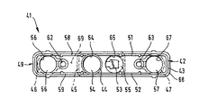
【図6】図4による装置の上面図。
【符号の説明】
11 装置
12 カバーインサート
14 管状壁部
15 側壁部
16 管状壁部
18 ピペットチップ
19 室
24 収容室
25 廃液室
26 第1処理室
32 第1みぞ
34 開口
38 側壁部
39 底壁部
42 カバーインサート
47 管状壁部
48 ピペットチップ
49 室
55 廃液室
56 第1処理室
57 第2処理室
62 第1みぞ
63 第2みぞ
64 開口
65 開口
67 開口
69 底壁部[0001]
BACKGROUND OF THE INVENTION
The present invention relates to a disposable device for carrying out a method in which a biological sample is treated with one or more reagents.
The invention relates in particular to a disposable device of this kind which is suitable for carrying out a method for obtaining a purified nucleic acid sample from a biological sample.
The invention further relates to the use of such a device for treating a biological fluid sample with one or more reagents to obtain a purified nucleic acid sample.
[0002]
[Background Art and Problems to be Solved by the Invention]
For example, known methods for obtaining purified nucleic acid samples that are suitable to be amplified by polymerase chain reaction (PCR) are usually performed manually and liquid by several steps, especially multiple pipetting Including transport. This manual method has to be carried out with great care since the contamination of the sample to be obtained has to be reduced as much as possible and is therefore a time consuming operation.
[0003]
A known device for automatically carrying out the work of transferring liquids by pipetting in an analytical device is for example to obtain a purified nucleic acid sample which is preferably amplified by the polymerase chain reaction (PCR) It was found to be insufficient as a method. This is because contamination of the sample tends to occur during liquid transfer by pipetting.
[0004]
[Means for Solving the Problems]
Therefore, the main object of the present invention is to meet the requirements of a nucleic acid purification method that provides a nucleic acid sample that has a high degree of purity and is therefore suitable to be amplified, for example, by polymerase chain reaction (PCR). It is an object of the present invention to provide an apparatus of the type briefly described in the introduction which has been devised for carrying out automatic processing which does not cause sample and reagent contamination to a sufficient extent.
[0005]
According to the first aspect of the present invention, this problem is caused by the disposable processing device.
a) comprising an integrally configured array of chambers, an integrally configured cover insert and a disposable pipette tip;
b) The arrangement of the integrally configured chambers is
b. 1) an upper portion formed as an elongated tray and having an inner portion delimited by a bottom wall portion and a side wall portion extending perpendicularly to and along the periphery of the bottom wall portion;
b. 2) an open upper end and a closed bottom end connected by a tubular wall extending substantially perpendicular to the bottom wall of the upper portion and extending downwardly from the first opening of the bottom wall. And the first opening forms an open upper end of the first processing chamber, and
b. 3) A waste liquid chamber for receiving the waste liquid is provided, and the waste liquid chamber is connected to the bottom wall portion of the upper portion by a side wall portion extending substantially perpendicularly and downward from the second opening of the bottom wall portion. An open upper end and a closed bottom end, the second opening forms an open upper end of the waste chamber,
c) the integrally constructed cover insert is shaped and dimensioned to be inserted into the array of chambers and the cover insert is
c. 1) an elongate cover having openings for accessing the treatment chamber and waste chamber, respectively, when the cover insert is inserted into the array of chambers;
c. 2) A storage chamber for storing the disposable pipette tip inside is provided, and the storage chamber is connected by a tubular wall portion extending substantially perpendicular to the cover and downward from the opening of the cover. Having an open top end and a closed bottom end,
d) The disposable pipette tip is solved by a disposable processing device characterized in that it is dimensioned to be inserted at least partially into the interior of the receiving chamber.
[0006]
According to a second aspect of the invention, the above object is achieved by using a device according to the invention for carrying out a method in which a biological fluid sample is treated with one or more reagents. . This method includes automatic transfer of liquid from a processing chamber to a waste chamber, or automatic transfer of liquid from a primary sample tube outside the apparatus to a first processing chamber, or from a processing chamber to a specimen container outside the apparatus. The liquid is transferred by a pipetting operation that is performed exclusively for a disposable pipette tip that is a part of the apparatus.
[0007]
The main advantage of the device and method according to the present invention is that the device and method provide a nucleic acid purification which provides a nucleic acid sample which has a high degree of purity and is therefore preferably amplified by eg polymerase chain reaction (PCR). It is possible to ensure automatic processing that does not cause contamination of the sample and the reagent to the extent that it sufficiently meets the requirements of the method.
[0008]
A further advantage of the device according to the invention is that a plurality of these devices can be used simultaneously in an automated device to obtain a corresponding plurality of purified nucleic acid samples from each biological sample.
[0009]
A particular advantage of an embodiment of the device according to the invention with only one processing chamber is that it is cheaper than a device with more than one processing chamber and the size of the device is small The amount of waste material that needs to be discarded after use is reduced, and the cost of packaging material for waste material is reduced.
[0010]
In a preferred embodiment of the device according to the invention, the cover comprises a first channel for accessing the interior of the process chamber for dispensing liquid into the process chamber, this dispensing being separate from the disposable pipette tip. It is characterized by being performed by a pipetting cannula. The advantage of this embodiment ensures that the groove is placed inside a substantially closed environment during pipetting, thereby handling the liquid from the pipetting cannula. It is to prevent the occurrence of unforeseen contamination while moving to the room.
[0011]
A further preferred embodiment of the device according to the invention is characterized in that a substantial part of the storage chamber is arranged inside the waste chamber when the cover insert is inserted into the array of chambers. Yes. This arrangement advantageously reduces the space occupied by the device, since no additional space is required for the containment chamber.
[0012]
Another preferred embodiment of the device according to the invention is characterized in that the processing chamber is freely suspended downward from the bottom wall of the upper part of the array of chambers. With this configuration, the lower part of the processing chamber is easily affected by an external device, for example, a magnet used to enable separation of magnetic particles in a suspended matter in a liquid contained in the processing chamber. Benefits are gained.
[0013]
A further preferred embodiment of the device according to the invention is such that the arrangement of the unitary chambers is further substantially perpendicular to the bottom wall of the upper part and below the third opening of the bottom wall. A second processing chamber having an open upper end connected by a tubular wall extending to the bottom and a closed bottom end, wherein the third opening forms an open upper end of the second processing chamber. It is characterized by that. The advantage of this embodiment is that it provides greater flexibility with respect to the sequence of processing steps for performing a particular method. This flexibility can be achieved, for example, by maintaining the processing chambers at different temperatures, for example, maintaining one of the processing chambers at 60 ° C. and maintaining the other at 37 ° C. Increased by use for temporary storage of reagents before being transported to.
[0014]
In a preferred embodiment of the device according to the invention comprising two processing chambers, the bottom wall of the upper part accesses the interior of the second processing chamber for dispensing liquid into the second processing chamber. And the dispensing is performed by a pipetting cannula separate from the disposable pipette tip. The advantage of this embodiment is that the second groove ensures that the pipetting cannula tip is placed inside a substantially closed environment during pipetting, thereby allowing liquid to be removed from the pipetting cannula. It is to prevent the occurrence of unforeseen contamination during transfer to the processing chamber.
[0015]
Another preferred embodiment of the device according to the invention comprising two processing chambers is characterized in that the first processing chamber, the waste liquid chamber and the second processing chamber are arranged in a row. This arrangement advantageously provides an array of devices according to the invention in an automatic processing device and a transport device used to move disposable pipette tips and pipetting cannulas to their pipetting positions with respect to the various chambers of the device. It is simplified.
[0016]
Another preferred embodiment according to the invention comprising two processing chambers is characterized in that the waste liquid chamber is arranged between the first processing chamber and the second processing chamber. This arrangement advantageously reduces the travel paths of these members required to move disposable pipette tips and pipetting cannulas to their pipetting positions relative to various positions of the device.
[0017]
A further preferred embodiment of the device according to the invention comprising two processing chambers. The second processing chamber is freely suspended downward from the bottom wall portion of the upper portion of the array of chambers. With this configuration, the lower portion of the second processing chamber is influenced by the magnet used to allow separation of magnetic particles in the suspended matter in the liquid contained in the external device, eg, the second processing chamber. The advantage is that it is easy to receive.
[0018]
A preferred embodiment of the device according to the invention is characterized in that the arrangement of the chambers of the device according to the invention is integrally formed of a plastic material.
[0019]
A preferred embodiment of the device according to the invention is characterized in that the cover insert of the device according to the invention is integrally formed of a plastic material.
In these preferred embodiments, it is possible to reduce the manufacturing cost of this device.
[0020]
A preferred use of the device according to the invention comprises the step of dispensing a liquid reagent from a reagent container outside the device into a processing chamber, in addition to a disposable pipette tip, the dispensing being part of the device. In order to carry out the method characterized in that it is carried out by means of a pipetting cannula.
[0021]
A preferred use of the device according to the invention comprising two processing chambers is that the method automatically transfers liquid from the first processing chamber to the second processing chamber, or vice versa, or the first processing. Automatic transfer of liquid from the chamber or the second processing chamber to the waste liquid chamber, or automatic transfer of liquid from the primary sample tube outside the apparatus to the first processing chamber or the second processing chamber, or the first processing chamber or the second processing chamber. Including a step of automatic transfer of liquid from a processing chamber to a specimen container outside the apparatus, and the transfer of the liquid is performed by a pipette operation performed exclusively for a disposable pipette tip that is part of the apparatus. In order to implement the method characterized by the above.
[0022]
A further preferred use of the device according to the invention comprising two processing chambers is that the method distributes the liquid reagent from the reagent container outside the device into the first processing chamber and / or the second processing chamber. And the dispensing is performed by another pipetting cannula of a disposable pipette tip that is part of the device.
[0023]
A preferred use of the device according to the invention is for carrying out a method for separating nucleic acids contained in a biological sample.
[0024]
DETAILED DESCRIPTION OF THE INVENTION
Preferred embodiments of the present invention will now be described with reference to the accompanying drawings.
1 to 3 show a first embodiment of a
[0025]
The arrangement of
An upper part formed as an elongated tray and having an inner part bounded by a
A
A
[0026]
The
[0027]
The
[0028]
An
A
[0029]
In a preferred embodiment, the
[0030]
The
[0031]
The
[0032]
The upper portion of the
[0033]
In the preferred embodiment shown in FIG. 2, the
[0034]
In the preferred embodiment shown in FIGS. 1-3, the
[0035]
The shape of the
[0036]
In the preferred embodiment shown in FIGS. 1-3, the
[0037]
In a preferred embodiment, the shape and dimensions of this array of protrusions and the shape and dimensions of the upper portion of the
[0038]
The
As shown in FIGS. 1 and 2, when the
[0039]
4 to 6 show a second embodiment of the
[0040]
The arrangement of
An upper portion formed as an elongated tray and having an inner portion delimited by a
-A
-A
A
[0041]
The
[0042]
The
The
[0043]
The
[0044]
An
A
[0045]
In a preferred embodiment, the
[0046]
The
[0047]
The
[0048]
The upper portion of the
[0049]
In the preferred embodiment shown in FIGS. 4-6, the
[0050]
The shape of the
In the preferred embodiment shown in FIGS. 4-6, the
[0051]
In a preferred embodiment, the shape and dimensions of this array of protrusions and the shape and dimensions of the upper portion of the
[0052]
The
[0053]
As shown in FIGS. 4 and 5, when the
In a preferred embodiment, the
In a further preferred embodiment, the
[0054]
In a preferred embodiment of the device according to the invention, the respective array of
[0055]
When the
[0056]
When the
[0057]
Device according to the invention41A preferred use of is to carry out a process for separating nucleic acids contained in a biological sample. Such a process includes, for example, the following steps:
A) Equipment41Is transported from the storage position to the culture position in the incubator by the gripper of the transport mechanism of the automatic device.
B) The lysis solution from the outer container is treated by the pipette cannula of the automatic pipette transfer device.56Transfer by pipetting.
C) A predetermined amount of biological fluid sample from an external container is treated by the
D) Processing room for internal quality reference solution from external container by pipette cannula of automatic pipetting device56Pipet inside.
E) Processing chamber for so-called probe solution from external container by pipette cannula of automatic pipetting device57Pipet inside.
F) Processing room56The mixture contained therein is cultured at 60 ° C.
G) Pipette tip48By processing chamber56The entire liquid mixture contained in the processing chamber57Pipet to move.
H) Processing room57The mixture contained therein is incubated at 37 ° C.
I) A bead (solid phase) solution from an external container is treated by a pipette cannula of an automatic pipetting device.57Pipet inside.
J) Processing room57The mixture contained therein is incubated at 37 ° C.
K) Equipment41Is transferred from the culture position in the incubator to the separation position of the automatic apparatus and the processing position in the washing station by the gripper of the automatic mechanism.
L) At the separation and cleaning station, the processing chamber57Several washing steps of beads contained in the chamber are carried out and waste liquid is discharged from this chamber55Disposable pipette tips48It is transferred by.
M) Processing room57Disposable pipette tip containing target solution containing nucleic acid remaining in and separated into an external specimen container48Use pipette to move.
[0058]
LikeMethod for separating nucleic acid contained in a biological sampleMay be carried out using the
[Brief description of the drawings]
FIG. 1 is a perspective view of a first embodiment according to the present invention.
FIG. 2 is a cross-sectional view of FIG. 1 taken along line II-II.
3 shows a top view of the device according to FIG.
FIG. 4 is a perspective view of a second embodiment of the device according to the invention.
FIG. 5 is a cross-sectional view of FIG. 4 taken along line VV.
6 shows a top view of the device according to FIG.
[Explanation of symbols]
11 Equipment
12 Cover insert
14 Tubular wall
15 Side wall
16 Tubular wall
18 Pipette tips
19 rooms
24 containment room
25 Waste liquid chamber
26 First processing chamber
32 First Groove
34 Opening
38 Side wall
39 Bottom wall
42 Cover insert
47 Tubular wall
48 pipette tips
49 rooms
55 Waste liquid chamber
56 First processing chamber
57 Second processing chamber
62 First Groove
63 Second Groove
64 openings
65 opening
67 opening
69 Bottom wall
Claims (6)
前記室の配列は、
細長いトレーとして形成されていて、底壁部及び該底壁部の周囲に対して垂直にかつ該周囲に沿って延びている側壁部によって境界が定められた内側部を有する上側部分と、
前記上側部分の底壁部に対して実質的に垂直にかつ前記底壁部の第1開口から下方に延びている管状壁部によって連結された、開口した上端部及び閉ざされた底端部を有する第1処理室にして、前記第1開口が該第1処理室の開口した上端部を形成している、前記第1処理室と、
廃液を受け入れるための廃液室にして、該廃液室は前記上側部分の底壁部に対して実質的に垂直に、かつ前記底壁部の第2開口から下方に延びている側壁部によって連結された、開口した上端部及び閉ざされた底端部を有し、前記第2開口は前記廃液室の開口した上端部を形成している、前記廃液室とを含み、
前記カバーインサートは前記室の配列の前記上側部分内に挿入される形状と寸法とを有しており、このカバーインサートは、
前記カバーインサートが前記室の配列の前記上側部分内に挿入されたときに前記処理室及び前記廃液室のそれぞれにアクセスするための開口を有する細長いカバーと、
内部に前記使い捨てピペットチップを収容するための収容室にして、該収容室は前記カバーに対して実質的に垂直にかつ該カバーの開口から下方に延びている管状壁部によって連結された、開口した上端部及び閉ざされた底端部を有する、前記収容室とを含み、
前記使い捨てピペットチップは前記収容室の内部に少なくとも部分的に挿入されるような形状と寸法とを有していることを特徴とする、前記装置。An apparatus for carrying out a method in which a biological sample is treated with one or more reagents, the apparatus being connected to an array of chambers connected together and removably connected to the array of chambers. Cover inserts and disposable pipette tips,
The arrangement of the chambers is
An upper portion formed as an elongated tray and having an inner portion delimited by a bottom wall and a side wall extending perpendicularly to and along the periphery of the bottom wall;
An open top end and a closed bottom end connected by a tubular wall extending substantially perpendicular to the bottom wall of the upper portion and downwardly from a first opening in the bottom wall; The first processing chamber, wherein the first opening forms an open upper end of the first processing chamber; and
A waste liquid chamber for receiving waste liquid, the waste liquid chamber being connected by a side wall portion extending substantially perpendicular to the bottom wall portion of the upper portion and downward from the second opening of the bottom wall portion. The waste liquid chamber has an open upper end and a closed bottom end, and the second opening forms an open upper end of the waste liquid chamber;
The cover insert has a shape and dimensions that are inserted into the upper portion of the array of chambers, the cover insert being
An elongate cover having openings for accessing each of the process chamber and the waste chamber when the cover insert is inserted into the upper portion of the array of chambers;
An opening which is a receiving chamber for receiving the disposable pipette tip therein, the receiving chamber being connected by a tubular wall extending substantially perpendicular to the cover and downward from the opening of the cover. The storage chamber having a closed top end and a closed bottom end,
The apparatus of claim 1, wherein the disposable pipette tip is shaped and dimensioned to be at least partially inserted into the receiving chamber.
(i)前記第1の処理室から前記廃液室へ、
(ii)前記装置の外部の一次試料管から前記第1の処理室へ、
(iii)前記第1の処理室から前記装置の外部の試験体容器へ、自動的に移送する諸段階を含み、
これら諸段階の各段階における液体の移送が、前記ピペットチップを用いて実施されるピペット操作によって行なわれ、前記ピペットチップは、前記ピペット操作のそれぞれの間は前記収容室内に収容されていることを特徴とする方法。The apparatus is used to process a liquid biological sample with one or more reagents so that the apparatus includes a first processing chamber, a waste chamber, and a processing chamber and a waste chamber. A removable cover insert, each having an accessible opening , and a chamber for receiving a pipette tip cooperating with the device, the method comprising the following steps of automatically transferring liquid: That is,
(I) From the first treatment chamber to the waste liquid chamber,
(Ii) from a primary sample tube outside the apparatus to the first processing chamber;
(Iii) automatically transferring from the first processing chamber to a specimen container external to the apparatus;
The transfer of the liquid in each of these stages is performed by a pipette operation performed using the pipette tip, and the pipette tip is accommodated in the accommodation chamber during each of the pipette operations. Feature method.
Applications Claiming Priority (2)
| Application Number | Priority Date | Filing Date | Title |
|---|---|---|---|
| EP97109302 | 1997-06-09 | ||
| EP97109302.6 | 1997-06-09 |
Publications (2)
| Publication Number | Publication Date |
|---|---|
| JPH119258A JPH119258A (en) | 1999-01-19 |
| JP4056624B2 true JP4056624B2 (en) | 2008-03-05 |
Family
ID=8226894
Family Applications (1)
| Application Number | Title | Priority Date | Filing Date |
|---|---|---|---|
| JP13325798A Expired - Lifetime JP4056624B2 (en) | 1997-06-09 | 1998-05-15 | Disposable processing equipment |
Country Status (7)
| Country | Link |
|---|---|
| US (2) | US6063341A (en) |
| EP (1) | EP0884104B1 (en) |
| JP (1) | JP4056624B2 (en) |
| AT (1) | ATE306324T1 (en) |
| CA (1) | CA2233101C (en) |
| DE (1) | DE69831830T2 (en) |
| ES (1) | ES2249818T3 (en) |
Families Citing this family (68)
| Publication number | Priority date | Publication date | Assignee | Title |
|---|---|---|---|---|
| US6048734A (en) | 1995-09-15 | 2000-04-11 | The Regents Of The University Of Michigan | Thermal microvalves in a fluid flow method |
| CA2287962C (en) * | 1997-05-02 | 2007-01-02 | Gen-Probe Incorporated | Reaction receptacle apparatus |
| DE19963032A1 (en) | 1999-12-24 | 2001-06-28 | Roche Diagnostics Gmbh | System for processing samples in a multi-chamber arrangement |
| US6794193B2 (en) * | 2000-05-08 | 2004-09-21 | Arkray, Inc. | Method of assaying a specimen using a reagent |
| US7244392B1 (en) | 2000-05-22 | 2007-07-17 | Inverness Medical Switzerland Gmbh | Slide-in cassette for a cup for testing of drugs of abuse |
| US6576193B1 (en) | 2000-10-27 | 2003-06-10 | Shujie Cui | Device and method for collecting and testing fluid specimens |
| US6692700B2 (en) | 2001-02-14 | 2004-02-17 | Handylab, Inc. | Heat-reduction methods and systems related to microfluidic devices |
| US8895311B1 (en) | 2001-03-28 | 2014-11-25 | Handylab, Inc. | Methods and systems for control of general purpose microfluidic devices |
| US6852287B2 (en) | 2001-09-12 | 2005-02-08 | Handylab, Inc. | Microfluidic devices having a reduced number of input and output connections |
| US7010391B2 (en) | 2001-03-28 | 2006-03-07 | Handylab, Inc. | Methods and systems for control of microfluidic devices |
| US7323140B2 (en) | 2001-03-28 | 2008-01-29 | Handylab, Inc. | Moving microdroplets in a microfluidic device |
| US7829025B2 (en) | 2001-03-28 | 2010-11-09 | Venture Lending & Leasing Iv, Inc. | Systems and methods for thermal actuation of microfluidic devices |
| US7731906B2 (en) | 2003-07-31 | 2010-06-08 | Handylab, Inc. | Processing particle-containing samples |
| AU2005241080B2 (en) | 2004-05-03 | 2011-08-11 | Handylab, Inc. | Processing polynucleotide-containing samples |
| US8852862B2 (en) | 2004-05-03 | 2014-10-07 | Handylab, Inc. | Method for processing polynucleotide-containing samples |
| US20060264783A1 (en) | 2005-05-09 | 2006-11-23 | Holmes Elizabeth A | Systems and methods for monitoring pharmacological parameters |
| US20070020151A1 (en) | 2005-07-20 | 2007-01-25 | Steven Woodside | Pipette tip holder |
| EP1767274B1 (en) * | 2005-09-26 | 2015-09-09 | QIAGEN GmbH | Method for processing a fluid |
| US8883490B2 (en) | 2006-03-24 | 2014-11-11 | Handylab, Inc. | Fluorescence detector for microfluidic diagnostic system |
| JP5415253B2 (en) | 2006-03-24 | 2014-02-12 | ハンディラブ・インコーポレーテッド | Integrated system for processing microfluidic samples and methods of use thereof |
| US10900066B2 (en) | 2006-03-24 | 2021-01-26 | Handylab, Inc. | Microfluidic system for amplifying and detecting polynucleotides in parallel |
| US8088616B2 (en) | 2006-03-24 | 2012-01-03 | Handylab, Inc. | Heater unit for microfluidic diagnostic system |
| US7998708B2 (en) * | 2006-03-24 | 2011-08-16 | Handylab, Inc. | Microfluidic system for amplifying and detecting polynucleotides in parallel |
| US11806718B2 (en) | 2006-03-24 | 2023-11-07 | Handylab, Inc. | Fluorescence detector for microfluidic diagnostic system |
| US8246919B2 (en) | 2006-09-21 | 2012-08-21 | Abbott Laboratories | Specimen sample rack |
| WO2008061165A2 (en) | 2006-11-14 | 2008-05-22 | Handylab, Inc. | Microfluidic cartridge and method of making same |
| US9186677B2 (en) | 2007-07-13 | 2015-11-17 | Handylab, Inc. | Integrated apparatus for performing nucleic acid extraction and diagnostic testing on multiple biological samples |
| USD621060S1 (en) | 2008-07-14 | 2010-08-03 | Handylab, Inc. | Microfluidic cartridge |
| US20090136385A1 (en) | 2007-07-13 | 2009-05-28 | Handylab, Inc. | Reagent Tube |
| US9618139B2 (en) * | 2007-07-13 | 2017-04-11 | Handylab, Inc. | Integrated heater and magnetic separator |
| US8105783B2 (en) | 2007-07-13 | 2012-01-31 | Handylab, Inc. | Microfluidic cartridge |
| US8182763B2 (en) | 2007-07-13 | 2012-05-22 | Handylab, Inc. | Rack for sample tubes and reagent holders |
| US8287820B2 (en) | 2007-07-13 | 2012-10-16 | Handylab, Inc. | Automated pipetting apparatus having a combined liquid pump and pipette head system |
| WO2009012185A1 (en) | 2007-07-13 | 2009-01-22 | Handylab, Inc. | Polynucleotide capture materials, and methods of using same |
| AU2013205253B8 (en) * | 2007-07-13 | 2015-10-22 | Handylab, Inc. | Integrated apparatus for performing nucleic acid extraction and diagnostic testing on multiple biological samples |
| US8133671B2 (en) | 2007-07-13 | 2012-03-13 | Handylab, Inc. | Integrated apparatus for performing nucleic acid extraction and diagnostic testing on multiple biological samples |
| AU2008308686B2 (en) | 2007-10-02 | 2015-01-22 | Labrador Diagnostics Llc | Modular point-of-care devices and uses thereof |
| USD618820S1 (en) | 2008-07-11 | 2010-06-29 | Handylab, Inc. | Reagent holder |
| USD787087S1 (en) | 2008-07-14 | 2017-05-16 | Handylab, Inc. | Housing |
| US20110308336A1 (en) * | 2010-06-16 | 2011-12-22 | Identigene, L.L.C. | Methods and apparatus for specimen collection and transport |
| CN103551212B (en) * | 2010-07-23 | 2016-01-20 | 贝克曼考尔特公司 | Kit |
| US9144801B2 (en) | 2010-08-31 | 2015-09-29 | Abbott Laboratories | Sample tube racks having retention bars |
| AR085087A1 (en) | 2011-01-21 | 2013-09-11 | Theranos Inc | SYSTEMS AND METHODS TO MAXIMIZE THE USE OF SAMPLES |
| CN106190806B (en) | 2011-04-15 | 2018-11-06 | 贝克顿·迪金森公司 | Scan real-time microfluid thermal cycler and the method for synchronous thermal cycle and scanning optical detection |
| US20140170735A1 (en) | 2011-09-25 | 2014-06-19 | Elizabeth A. Holmes | Systems and methods for multi-analysis |
| US8840838B2 (en) | 2011-09-25 | 2014-09-23 | Theranos, Inc. | Centrifuge configurations |
| US8475739B2 (en) | 2011-09-25 | 2013-07-02 | Theranos, Inc. | Systems and methods for fluid handling |
| US9619627B2 (en) | 2011-09-25 | 2017-04-11 | Theranos, Inc. | Systems and methods for collecting and transmitting assay results |
| US9632102B2 (en) | 2011-09-25 | 2017-04-25 | Theranos, Inc. | Systems and methods for multi-purpose analysis |
| US9268915B2 (en) | 2011-09-25 | 2016-02-23 | Theranos, Inc. | Systems and methods for diagnosis or treatment |
| US9664702B2 (en) | 2011-09-25 | 2017-05-30 | Theranos, Inc. | Fluid handling apparatus and configurations |
| US9250229B2 (en) | 2011-09-25 | 2016-02-02 | Theranos, Inc. | Systems and methods for multi-analysis |
| US10012664B2 (en) | 2011-09-25 | 2018-07-03 | Theranos Ip Company, Llc | Systems and methods for fluid and component handling |
| US9810704B2 (en) | 2013-02-18 | 2017-11-07 | Theranos, Inc. | Systems and methods for multi-analysis |
| KR102121853B1 (en) | 2011-09-30 | 2020-06-12 | 벡톤 디킨슨 앤드 컴퍼니 | Unitized reagent strip |
| USD692162S1 (en) | 2011-09-30 | 2013-10-22 | Becton, Dickinson And Company | Single piece reagent holder |
| CN104040238B (en) | 2011-11-04 | 2017-06-27 | 汉迪拉布公司 | Polynucleotides sample preparation apparatus |
| EP2607904B1 (en) * | 2011-12-21 | 2020-01-15 | Roche Diagnostics GmbH | Method for disposing of a liquid within an automated analytical system, tip rack assembly and analytical system |
| CN107881219B (en) | 2012-02-03 | 2021-09-10 | 贝克顿·迪金森公司 | External file for molecular diagnostic test assignment and compatibility determination between tests |
| EP2703820B1 (en) | 2012-08-31 | 2019-08-28 | F. Hoffmann-La Roche AG | Mobile tip waste rack |
| AU2013202778A1 (en) | 2013-03-14 | 2014-10-02 | Gen-Probe Incorporated | Systems, methods, and apparatuses for performing automated reagent-based assays |
| US9632103B2 (en) | 2013-03-15 | 2017-04-25 | Abbott Laboraties | Linear track diagnostic analyzer |
| WO2014144870A2 (en) | 2013-03-15 | 2014-09-18 | Abbott Laboratories | Light-blocking system for a diagnostic analyzer |
| CN105164511B (en) | 2013-03-15 | 2019-03-22 | 雅培实验室 | The automated reagent manager of diagnostic analysis device system |
| US11545241B1 (en) | 2013-09-07 | 2023-01-03 | Labrador Diagnostics Llc | Systems and methods for analyte testing and data management |
| USD814653S1 (en) | 2014-08-07 | 2018-04-03 | Becton, Dickinson And Company | Sample tube holder and components thereof |
| EP3213819B1 (en) | 2016-03-02 | 2021-09-29 | F. Hoffmann-La Roche AG | Device and method for separation |
| JP7129483B2 (en) * | 2018-01-23 | 2022-09-01 | エフ.ホフマン-ラ ロシュ アーゲー | A tube tray for secondary tubes, a secondary tube handling module, and a method for handling secondary tubes in an automated processing system. |
Family Cites Families (17)
| Publication number | Priority date | Publication date | Assignee | Title |
|---|---|---|---|---|
| US3785773A (en) * | 1972-03-02 | 1974-01-15 | Beckman Instruments Inc | Chemical analysis tube module |
| US4287155A (en) * | 1980-06-16 | 1981-09-01 | Eastman Kodak Company | Sample tray and carrier for chemical analyzer |
| US4391780A (en) * | 1981-07-06 | 1983-07-05 | Beckman Instruments, Inc. | Container for sample testing |
| SU1671531A1 (en) * | 1988-10-20 | 1991-08-23 | Харьковский научно-исследовательский институт терапии | Device for storing biologic liquids |
| IL94408A0 (en) * | 1989-07-11 | 1991-03-10 | Miles Inc | Method,reaction cassette and kit for performing analytical assays |
| GB2243446B (en) * | 1990-04-25 | 1994-05-25 | Pfizer Ltd | An assay tray and assembly |
| AU639575B2 (en) * | 1990-05-01 | 1993-07-29 | Enprotech Corporation | Integral biomolecule preparation device |
| JPH0675497B2 (en) * | 1990-11-15 | 1994-09-28 | 倉敷紡績株式会社 | Plasmid separation device |
| JPH074220B2 (en) * | 1991-01-16 | 1995-01-25 | 倉敷紡績株式会社 | Automatic plasmid separator |
| SE503729C2 (en) * | 1991-03-11 | 1996-08-12 | Mats Malmquist | extraction |
| FR2678950B1 (en) * | 1991-07-09 | 1993-11-05 | Bertin Et Cie | CARTRIDGE, DEVICE AND METHOD FOR EXTRACTING NUCLEIC ACIDS SUCH AS DNA FROM A SAMPLE OF BLOOD OR TISSUE CELLS. |
| US5438128A (en) * | 1992-02-07 | 1995-08-01 | Millipore Corporation | Method for rapid purifiction of nucleic acids using layered ion-exchange membranes |
| US5330439A (en) * | 1992-04-08 | 1994-07-19 | American National Red Cross | Safety device for use in collecting fluid samples |
| EP1245286B1 (en) * | 1993-10-22 | 2009-11-25 | Abbott Laboratories | Reaction tube and method of use to minimize contamination |
| US5609822A (en) * | 1995-07-07 | 1997-03-11 | Ciba Corning Diagnostics Corp. | Reagent handling system and reagent pack for use therein |
| CA2226717A1 (en) * | 1995-07-13 | 1997-01-30 | Immunological Associates Of Denver | Self-contained device integrating nucleic acid extraction, amplification and detection |
| JP3985872B2 (en) * | 1995-07-31 | 2007-10-03 | プレシジョン・システム・サイエンス株式会社 | container |
-
1998
- 1998-03-11 ES ES98810205T patent/ES2249818T3/en not_active Expired - Lifetime
- 1998-03-11 AT AT98810205T patent/ATE306324T1/en active
- 1998-03-11 DE DE69831830T patent/DE69831830T2/en not_active Expired - Lifetime
- 1998-03-11 EP EP98810205A patent/EP0884104B1/en not_active Expired - Lifetime
- 1998-04-01 CA CA002233101A patent/CA2233101C/en not_active Expired - Fee Related
- 1998-05-15 JP JP13325798A patent/JP4056624B2/en not_active Expired - Lifetime
- 1998-06-09 US US09/093,776 patent/US6063341A/en not_active Expired - Lifetime
-
2000
- 2000-02-22 US US09/510,924 patent/US6506610B1/en not_active Expired - Lifetime
Also Published As
| Publication number | Publication date |
|---|---|
| US6506610B1 (en) | 2003-01-14 |
| CA2233101A1 (en) | 1998-12-09 |
| ES2249818T3 (en) | 2006-04-01 |
| JPH119258A (en) | 1999-01-19 |
| CA2233101C (en) | 2006-12-05 |
| DE69831830D1 (en) | 2006-02-23 |
| US6063341A (en) | 2000-05-16 |
| EP0884104B1 (en) | 2005-10-12 |
| ATE306324T1 (en) | 2005-10-15 |
| EP0884104A1 (en) | 1998-12-16 |
| DE69831830T2 (en) | 2006-06-22 |
Similar Documents
| Publication | Publication Date | Title |
|---|---|---|
| JP4056624B2 (en) | Disposable processing equipment | |
| JP6514173B2 (en) | Multiwell plate and lid | |
| US7427510B2 (en) | System for processing samples in a multichamber arrangement | |
| EP2192186B1 (en) | System and method for the automated extraction of nucleic acids | |
| EP2223745B1 (en) | Method of loading reagent in a specimen handling device of an automated testing device | |
| EP1340982B1 (en) | Assay work station | |
| CA2724132C (en) | Amplification system with spatial separation | |
| EP2338596A1 (en) | Tip rack | |
| EP2333558B1 (en) | Form-locking gripping system | |
| JP6039395B2 (en) | Preventing contamination | |
| CN115948224A (en) | Automatic biological sample extraction system and device | |
| EP2423688B1 (en) | Suspension container for binding particles for the isolation of biological material | |
| US20220168733A1 (en) | Device and method for the extraction of nucleic acids | |
| US20240061004A1 (en) | System and apparatus for automated sample extracting of biological specimens | |
| GB2618578A (en) | Method and consumable for nucleic acid extraction | |
| AU769762B2 (en) | A substance transfer device | |
| CN110945363A (en) | Module for transferring magnetic beads, automated system comprising the module, and method for extracting nucleic acid using the module |
Legal Events
| Date | Code | Title | Description |
|---|---|---|---|
| A521 | Request for written amendment filed |
Free format text: JAPANESE INTERMEDIATE CODE: A523 Effective date: 20041130 |
|
| A621 | Written request for application examination |
Free format text: JAPANESE INTERMEDIATE CODE: A621 Effective date: 20041130 |
|
| A131 | Notification of reasons for refusal |
Free format text: JAPANESE INTERMEDIATE CODE: A131 Effective date: 20070810 |
|
| A521 | Request for written amendment filed |
Free format text: JAPANESE INTERMEDIATE CODE: A523 Effective date: 20071108 |
|
| TRDD | Decision of grant or rejection written | ||
| A01 | Written decision to grant a patent or to grant a registration (utility model) |
Free format text: JAPANESE INTERMEDIATE CODE: A01 Effective date: 20071204 |
|
| A61 | First payment of annual fees (during grant procedure) |
Free format text: JAPANESE INTERMEDIATE CODE: A61 Effective date: 20071212 |
|
| R150 | Certificate of patent or registration of utility model |
Free format text: JAPANESE INTERMEDIATE CODE: R150 |
|
| FPAY | Renewal fee payment (event date is renewal date of database) |
Free format text: PAYMENT UNTIL: 20101221 Year of fee payment: 3 |
|
| FPAY | Renewal fee payment (event date is renewal date of database) |
Free format text: PAYMENT UNTIL: 20111221 Year of fee payment: 4 |
|
| FPAY | Renewal fee payment (event date is renewal date of database) |
Free format text: PAYMENT UNTIL: 20121221 Year of fee payment: 5 |
|
| FPAY | Renewal fee payment (event date is renewal date of database) |
Free format text: PAYMENT UNTIL: 20121221 Year of fee payment: 5 |
|
| FPAY | Renewal fee payment (event date is renewal date of database) |
Free format text: PAYMENT UNTIL: 20131221 Year of fee payment: 6 |
|
| R250 | Receipt of annual fees |
Free format text: JAPANESE INTERMEDIATE CODE: R250 |
|
| R250 | Receipt of annual fees |
Free format text: JAPANESE INTERMEDIATE CODE: R250 |
|
| R250 | Receipt of annual fees |
Free format text: JAPANESE INTERMEDIATE CODE: R250 |
|
| R250 | Receipt of annual fees |
Free format text: JAPANESE INTERMEDIATE CODE: R250 |
|
| R250 | Receipt of annual fees |
Free format text: JAPANESE INTERMEDIATE CODE: R250 |
|
| EXPY | Cancellation because of completion of term |