JP4055819B2 - POWER OUTPUT DEVICE, ITS CONTROL METHOD, AND HYBRID VEHICLE - Google Patents
POWER OUTPUT DEVICE, ITS CONTROL METHOD, AND HYBRID VEHICLE Download PDFInfo
- Publication number
- JP4055819B2 JP4055819B2 JP2007044063A JP2007044063A JP4055819B2 JP 4055819 B2 JP4055819 B2 JP 4055819B2 JP 2007044063 A JP2007044063 A JP 2007044063A JP 2007044063 A JP2007044063 A JP 2007044063A JP 4055819 B2 JP4055819 B2 JP 4055819B2
- Authority
- JP
- Japan
- Prior art keywords
- power
- output
- motor
- electric motor
- shaft
- Prior art date
- Legal status (The legal status is an assumption and is not a legal conclusion. Google has not performed a legal analysis and makes no representation as to the accuracy of the status listed.)
- Expired - Fee Related
Links
Images


Classifications
-
- Y—GENERAL TAGGING OF NEW TECHNOLOGICAL DEVELOPMENTS; GENERAL TAGGING OF CROSS-SECTIONAL TECHNOLOGIES SPANNING OVER SEVERAL SECTIONS OF THE IPC; TECHNICAL SUBJECTS COVERED BY FORMER USPC CROSS-REFERENCE ART COLLECTIONS [XRACs] AND DIGESTS
- Y02—TECHNOLOGIES OR APPLICATIONS FOR MITIGATION OR ADAPTATION AGAINST CLIMATE CHANGE
- Y02T—CLIMATE CHANGE MITIGATION TECHNOLOGIES RELATED TO TRANSPORTATION
- Y02T10/00—Road transport of goods or passengers
- Y02T10/60—Other road transportation technologies with climate change mitigation effect
- Y02T10/62—Hybrid vehicles
-
- Y—GENERAL TAGGING OF NEW TECHNOLOGICAL DEVELOPMENTS; GENERAL TAGGING OF CROSS-SECTIONAL TECHNOLOGIES SPANNING OVER SEVERAL SECTIONS OF THE IPC; TECHNICAL SUBJECTS COVERED BY FORMER USPC CROSS-REFERENCE ART COLLECTIONS [XRACs] AND DIGESTS
- Y02—TECHNOLOGIES OR APPLICATIONS FOR MITIGATION OR ADAPTATION AGAINST CLIMATE CHANGE
- Y02T—CLIMATE CHANGE MITIGATION TECHNOLOGIES RELATED TO TRANSPORTATION
- Y02T10/00—Road transport of goods or passengers
- Y02T10/60—Other road transportation technologies with climate change mitigation effect
- Y02T10/7072—Electromobility specific charging systems or methods for batteries, ultracapacitors, supercapacitors or double-layer capacitors
Landscapes
- Electric Propulsion And Braking For Vehicles (AREA)
- Hybrid Electric Vehicles (AREA)
Abstract
Description
本発明は、動力出力装置およびその制御方法並びにハイブリッド自動車に関する。 The present invention relates to a power output apparatus, a control method therefor, and a hybrid vehicle.
従来、この種の動力出力装置としては、エンジンと、2つのプラネタリギヤと、3つのモータと、2つのクラッチとを備え、駆動軸に動力を出力するものが提案されている(例えば、特許文献1参照)。この装置の第1プラネタリギヤのキャリアには、エンジンのクランクシャフトが接続されており、サンギヤには第2プラネタリギヤのサンギヤと第1クラッチを介して第1モータとが接続されている。また、第1プラネタリギヤのリングギヤには、車軸に機械的に連結された駆動軸と第2プラネタリギヤのキャリアと第2モータとが接続されている。第2プラネタリギヤのリングギヤには、第3モータと第2クラッチを介して第1モータとが接続されている。したがって、第2プラネタリギヤのリングギヤは、2つのクラッチを介して第1プラネタリギヤのサンギヤにも接続されていることになる。この動力出力装置では、2つのクラッチによる切り替えや3つのモータの駆動パターン,エンジンの運転パターンなどにより種々の駆動状態を可能なものとなっている。
しかしながら、こうした動力出力装置では、エンジンと2つのプラネタリギヤと3つのモータと2つのクラッチとを備えることから、装置が複雑なものとなっている。また、2つのクラッチを作動させる必要から、油圧回路などのアクチュエータも必要となる。更に、装置の駆動状態として種々可能であるが、駆動状態によってはエネルギ的に不利益なものもあり、エネルギ効率の観点から駆動状態を選択する必要もある。加えて、異なる駆動状態への切り替えをスムーズに行なう必要もある。特に、こうした動力出力装置を自動車に搭載する場合には、駆動状態の頻繁な切り替えが生じないよう車両の走行状態に合わせて切り替える必要がある。 However, in such a power output apparatus, since the engine, two planetary gears, three motors, and two clutches are provided, the apparatus is complicated. Moreover, since it is necessary to operate two clutches, an actuator such as a hydraulic circuit is also required. Furthermore, although various driving states of the apparatus are possible, some driving states are disadvantageous in terms of energy, and it is necessary to select a driving state from the viewpoint of energy efficiency. In addition, it is necessary to smoothly switch to different driving states. In particular, when such a power output device is mounted on an automobile, it is necessary to switch according to the traveling state of the vehicle so that frequent switching of the driving state does not occur.
本発明の動力出力装置は、装置の簡易化を図ることを目的の一つとする。また、本発明の動力出力装置およびその制御方法並びにハイブリッド自動車は、エネルギ効率の向上を図ることを目的の一つとする。さらに、本発明の動力出力装置およびその制御方法並びにハイブリッド自動車は、動力出力装置の異なる駆動状態の切り替えをスムーズに行なうことを目的の一つとする。あるいは、本発明の動力出力装置およびその制御方法並びにハイブリッド自動車は、動力出力装置の駆動状態の頻繁な切り替えを抑制することを目的の一つとする。 The power output device of the present invention is one of the purposes for simplifying the device. Another object of the power output device, the control method thereof, and the hybrid vehicle of the present invention is to improve energy efficiency. Furthermore, it is an object of the power output apparatus, the control method thereof, and the hybrid vehicle of the present invention to smoothly switch between different driving states of the power output apparatus. Alternatively, a power output apparatus, a control method thereof, and a hybrid vehicle according to the present invention have an object to suppress frequent switching of the driving state of the power output apparatus.
本発明の動力出力装置およびその制御方法並びにハイブリッド自動車は、上述の目的の少なくとも一部を達成するために以下の手段を採った。 The power output apparatus, the control method thereof, and the hybrid vehicle of the present invention employ the following means in order to achieve at least a part of the above object.
本発明の動力出力装置は、
駆動軸に動力を出力する動力出力装置であって、
内燃機関と、
前記内燃機関の出力軸と前記駆動軸と第1の回転軸とに接続された3軸を有し、該3軸のうちいずれか2軸に入出力される動力に基づいて残余の軸に動力を入出力する第1の3軸式動力入出力手段と、
前記第1の回転軸に動力を入出力する第1の電動機と、
前記駆動軸に動力を入出力する第2の電動機と、
前記第1の3軸式動力入出力手段が有する3軸のうちのいずれか2軸に連結されて回転する第2の回転軸を有し、前記第1の回転軸に入出力される動力を該第2の回転軸に入出力される動力で置換可能な動力置換手段と、
前記第2の回転軸に動力を入出力する第3の電動機と、
前記第1の電動機と前記第2の電動機と前記第3の電動機のうちいずれの電動機とも電力のやりとりが可能な蓄電手段と、
を備えることを要旨とする。
The power output apparatus of the present invention is
A power output device that outputs power to a drive shaft,
An internal combustion engine;
There are three shafts connected to the output shaft of the internal combustion engine, the drive shaft, and the first rotating shaft, and the remaining shaft is powered based on the power input to and output from any two of the three shafts. A first three-axis power input / output means for inputting / outputting
A first electric motor that inputs and outputs power to the first rotating shaft;
A second electric motor that inputs and outputs power to the drive shaft;
The first three-axis power input / output means has a second rotating shaft that is connected to any two of the three axes and rotates, and the power input / output to / from the first rotating shaft. Power replacement means capable of replacement with power input / output to / from the second rotating shaft;
A third electric motor for inputting and outputting power to the second rotating shaft;
Power storage means capable of exchanging power with any of the first motor, the second motor, and the third motor;
It is a summary to provide.
この本発明の動力出力装置では、蓄電手段の充放電を伴って或いは蓄電手段の充放電なしに内燃機関から出力される動力を第1の3軸式動力入出力手段と第1の電動機と第2の電動機と動力置換手段と第3の電動機とによりトルク変換して駆動軸に出力することができる。その際、動力置換手段により第1の回転軸に入出力される動力を第2の回転軸に入出力される動力で置換できるから、第1の電動機の駆動と第3の電動機の駆動とを選択すること、即ち、第1の電動機の駆動を伴う駆動状態と第3の電動機の駆動を伴う駆動状態とのうちエネルギ効率の高い駆動状態を選択することができる。この結果、装置のエネルギ効率の向上を図ることができる。しかも、クラッチを備えないから、上述した従来例の動力出力装置に比して、装置を簡易なものにすることができる。 In the power output apparatus according to the present invention, the power output from the internal combustion engine with charge / discharge of the power storage means or without charge / discharge of the power storage means is transmitted to the first three-shaft power input / output means, the first electric motor, and the first motor. Torque conversion can be performed by the second electric motor, the power replacement means, and the third electric motor and output to the drive shaft. At that time, since the power input / output to / from the first rotating shaft can be replaced by the power input / output to / from the second rotating shaft by the power replacing means, the driving of the first motor and the driving of the third motor can be performed. In other words, a driving state with high energy efficiency can be selected from among a driving state involving driving of the first electric motor and a driving state involving driving of the third electric motor. As a result, the energy efficiency of the apparatus can be improved. In addition, since the clutch is not provided, the device can be simplified as compared with the above-described conventional power output device.
こうした本発明の動力出力装置において、前記動力置換手段は、前記内燃機関からの動力の少なくとも一部を正回転している前記駆動軸に出力するために前記第1の電動機の力行駆動が要求されるときに、該第1の電動機の力行駆動による前記第1の回転軸に動力を出力する状態の少なくとも一部の状態を前記第3の電動機の回生駆動による前記第2の回転軸に動力を出力する状態に置換可能な手段であるものとすることもできる。こうすれば、第1の電動機の力行駆動が要求されるときに、第1の電動機の力行駆動を第3の電動機の回生駆動に切り替えることができる。いま、蓄電手段の充放電なしに内燃機関から出力された動力をトルク変換して駆動軸に出力する場合を考える。第1の電動機の力行駆動が要求される状態では、電力収支を考えれば、第2の電動機は回生駆動が要求されることになる。この場合、駆動軸に出力された動力を第2の電動機によって電力に変換し、この変換した電力を第1の電動機により動力に変換して駆動軸より内燃機関側に位置する第1の3軸式動力入出力手段に出力する状態になる。この状態は、内燃機関から出力された動力と第1の電動機から出力された動力との和の動力の一部を第2の電動機で電力に変換して第1の電動機に供給する状態であり、いわゆる動力−電力−動力の循環(以下、動力循環という)が生じる。この動力循環は、循環する動力に電動機の効率を何度も作用させることから、装置全体としてはエネルギ効率の低下を招く。したがって、第1の電動機の力行駆動が要求されるときに第1の電動機の力行駆動を第3の電動機の回生駆動に切り替えることことにより、動力循環の状態を抑止して装置全体のエネルギ効率の向上を図ることができるのである。 In such a power output apparatus of the present invention, the power replacement means requires a power running drive of the first electric motor in order to output at least part of the power from the internal combustion engine to the drive shaft that is rotating forward. At least a part of the state in which power is output to the first rotating shaft by the power running drive of the first motor, the power to the second rotating shaft by the regenerative driving of the third motor. It can also be a means that can be replaced by the state to be output. If it carries out like this, when the power running drive of a 1st motor is requested | required, the power running drive of a 1st motor can be switched to the regenerative drive of a 3rd motor. Consider a case where the power output from the internal combustion engine is torque converted and output to the drive shaft without charging / discharging the power storage means. In a state where the power running drive of the first motor is required, the regenerative drive is required for the second motor in view of the power balance. In this case, the motive power output to the drive shaft is converted into electric power by the second electric motor, the converted electric power is converted into motive power by the first electric motor, and the first three shafts located on the internal combustion engine side from the drive shaft It will be in the state which outputs to a type power input / output means. This state is a state in which part of the sum of the power output from the internal combustion engine and the power output from the first electric motor is converted into electric power by the second electric motor and supplied to the first electric motor. In other words, so-called power-power-power circulation (hereinafter referred to as power circulation) occurs. This power circulation causes the efficiency of the electric motor to act on the circulated power many times, leading to a reduction in energy efficiency of the entire apparatus. Therefore, by switching the power running drive of the first motor to the regenerative drive of the third motor when the power running drive of the first motor is required, the state of power circulation is suppressed and the energy efficiency of the entire apparatus is reduced. Improvements can be made.
この第1の電動機の力行駆動の状態を第3の電動機の回生駆動の状態に置換可能な態様の本発明の動力出力装置において、前記内燃機関からの動力の少なくとも一部を正回転している前記駆動軸に出力するために前記第1の電動機の回生駆動が要求されるときには該第1の電動機を回生制御すると共に前記第3の電動機から前記第2の回転軸に動力が出力されないよう該第3の電動機を制御する第1の制御を実行し、前記内燃機関からの動力の少なくとも一部を正回転している前記駆動軸に出力するために前記第1の電動機の力行駆動が要求されるときには前記第1の電動機から前記第1の回転軸に動力が出力されないよう該第1の電動機を制御すると共に前記第3の電動機を回生制御する第2の制御を実行する制御手段を備えるものとすることもできる。こうすれば、動力循環を抑止することができ、装置のエネルギ効率を向上させることができる。この態様の本発明の動力出力装置において、前記制御手段は、前記第1の制御と前記第2の制御をヒステリシスをもって切り替える手段であるものとすることもできる。こうすれば、第1の制御と第2の制御とが頻繁に切り替わるのを抑止することができる。 In the power output apparatus of the present invention in which the state of powering drive of the first motor can be replaced with the state of regenerative drive of the third motor, at least a part of the power from the internal combustion engine is normally rotated. When regenerative driving of the first electric motor is required to output to the drive shaft, the first electric motor is regeneratively controlled and power is not output from the third electric motor to the second rotating shaft. In order to execute the first control for controlling the third electric motor and to output at least part of the power from the internal combustion engine to the drive shaft that is rotating in the forward direction, the power running drive of the first electric motor is required. Control means for controlling the first electric motor so that power is not output from the first electric motor to the first rotating shaft and executing second control for regenerative control of the third electric motor. Be And it can also be. In this way, power circulation can be suppressed and the energy efficiency of the device can be improved. In this aspect of the power output apparatus of the present invention, the control means may be means for switching between the first control and the second control with hysteresis. If it carries out like this, it can suppress that 1st control and 2nd control switch frequently.
第1の制御と第2の制御とを切り替える態様の本発明の動力出力装置において、前記駆動軸の回転数を検出する回転数検出手段を備え、前記制御手段は、前記回転数検出手段により検出された駆動軸の回転数が所定回転数未満のときには前記内燃機関からの動力の少なくとも一部を正回転している前記駆動軸に出力するために前記第1の電動機の力行駆動が要求されるときであっても前記第2の制御を実行せずに前記第1の電動機を力行制御すると共に前記第3の電動機から前記第2の回転軸に動力が出力されないよう該第3の電動機を制御する手段であるものとすることもできる。こうすれば、駆動軸の回転数が所定回転数未満のときには制御の切り替えなしに第1の制御により駆動軸に動力を出力し、駆動軸の回転数が所定回転数以上のときにだけ第1の制御から第2の制御に切り替えるものとすることができる。したがって、駆動軸の回転数が小さい状態における制御の切り替えを抑止することができる。この態様の本発明の動力出力装置において、前記制御手段は、前記回転数検出手段により検出された駆動軸の回転数の時間的な変化の割合が値0を含む所定範囲内のときに前記第1の制御と前記第2の制御との切り替えを行なう手段であるものとすることもできる。こうすれば、駆動軸の回転数が急変しているときには第1の制御と第2の制御との切り替えは行なわれないから、第1の制御と第2の制御とをスムーズに切り替えることができる。 In the power output apparatus of the present invention that switches between the first control and the second control, the power output device of the present invention further comprises a rotation speed detection means for detecting the rotation speed of the drive shaft, and the control means is detected by the rotation speed detection means. When the rotational speed of the driven shaft is less than a predetermined rotational speed, the first motor is required to be driven in order to output at least part of the power from the internal combustion engine to the drive shaft that is rotating forward. Even when the power is controlled, the first motor is controlled without performing the second control, and the third motor is controlled so that no power is output from the third motor to the second rotating shaft. It can also be a means to do. In this way, when the rotational speed of the drive shaft is less than the predetermined rotational speed, power is output to the drive shaft by the first control without switching the control, and only when the rotational speed of the drive shaft is equal to or higher than the predetermined rotational speed. The control can be switched to the second control. Therefore, it is possible to suppress control switching in a state where the rotational speed of the drive shaft is small. In this aspect of the power output apparatus according to the present invention, the control means is configured such that when the ratio of the temporal change in the rotational speed of the drive shaft detected by the rotational speed detection means is within a predetermined range including a value of 0, It may be a means for switching between the first control and the second control. By so doing, the first control and the second control are not switched when the rotational speed of the drive shaft is changing suddenly, so that the first control and the second control can be switched smoothly. .
また、第1の制御と第2の制御とを切り替える態様の本発明の動力出力装置において、前記制御手段は、前記第1の制御から前記第2の制御に切り替えるときには前記第2の回転軸の回転数が維持されるよう前記第3の電動機を回転数制御すると共に前記第1の電動機から出力されるトルクが値0に向けて徐変するよう該第1の電動機を駆動制御し、前記第2の制御から前記第1の制御に切り替えるときには前記第1の回転軸の回転数が維持されるよう前記第1の電動機を回転数制御すると共に前記第3の電動機から出力されるトルクが値0に向けて徐変するよう該第3の電動機を駆動制御する手段であるものとすることもできる。こうすれば、第1の制御と第2の制御とをスムーズに切り替えることができる。
In the power output apparatus of the present invention that switches between the first control and the second control, when the control means switches from the first control to the second control, the second rotating shaft The third electric motor is controlled so as to maintain the rotational speed, and the first motor is driven and controlled so that the torque output from the first motor gradually changes toward a value of 0, and the first electric motor is controlled. When switching from the
本発明の動力出力装置において、操作者の操作に基づいて前記駆動軸に出力すべき要求動力を設定する要求動力設定手段と、該設定された要求動力に基づいて前記内燃機関の運転ポイントを設定する運転ポイント設定手段と、を備え、前記制御手段は、前記設定された運転ポイントで前記内燃機関が運転されると共に前記設定された要求動力に応じた動力が前記駆動軸に出力されるよう前記内燃機関と前記第1の電動機と前記第2の電動機と前記第3の電動機とを制御する手段であるものとすることもできる。こうすれば、要求動力に応じた動力を駆動軸に出力することができる。この態様の本発明の動力出力装置において、前記制御手段は、前記設定された要求動力の時間的な変化の割合が値0を含む所定範囲内のときに前記第1の制御と前記第2の制御との切り替えを行なう手段であるものとすることもできる。こうすれば、要求動力が急変しているときには第1の制御と第2の制御との切り替えは行なわれないから、第1の制御と第2の制御とをスムーズに切り替えることができる。 In the power output apparatus of the present invention, a required power setting means for setting a required power to be output to the drive shaft based on an operation of an operator, and an operating point of the internal combustion engine is set based on the set required power Operating point setting means, wherein the control means operates the internal combustion engine at the set operating point and outputs power to the drive shaft according to the set required power. It may be a means for controlling the internal combustion engine, the first electric motor, the second electric motor, and the third electric motor. In this way, power according to the required power can be output to the drive shaft. In this aspect of the power output apparatus of the present invention, the control means includes the first control and the second control when the set time-dependent change rate of the required power is within a predetermined range including a value of zero. It can also be a means for switching to control. By so doing, switching between the first control and the second control is not performed when the required power changes suddenly, so that the first control and the second control can be switched smoothly.
本発明の動力出力装置において、前記動力置換手段は、前記第1の3軸式動力出力手段が有する3軸のうちのいずれか2軸と接続された2軸を有し、該2軸と前記第2の回転軸とからなる3軸のうちいずれか2軸に入出力される動力に基づいて残余の軸に動力を入出力する第2の3軸式動力入出力手段であるものとすることもできる。 In the power output apparatus of the present invention, the power replacement means has two axes connected to any two of the three axes of the first three-axis power output means, and the two axes and the It is assumed to be a second three-axis power input / output means for inputting / outputting power to / from the remaining shaft based on power input / output to / from any two of the three axes including the second rotating shaft. You can also.
本発明のハイブリッド自動車は、上述のいずれかの態様の本発明の動力出力装置、即ち、基本的には、駆動軸に動力を出力する動力出力装置であって、内燃機関と、前記内燃機関の出力軸と前記駆動軸と第1の回転軸とに接続された3軸を有し該3軸のうちいずれか2軸に入出力される動力に基づいて残余の軸に動力を入出力する第1の3軸式動力入出力手段と、前記第1の回転軸に動力を入出力する第1の電動機と、前記駆動軸に動力を入出力する第2の電動機と、前記第1の3軸式動力入出力手段が有する3軸のうちのいずれか2軸に連結されて回転する第2の回転軸を有し前記第1の回転軸に入出力される動力を該第2の回転軸に入出力される動力で置換可能な動力置換手段と、前記第2の回転軸に動力を入出力する第3の電動機と、前記第1の電動機と前記第2の電動機と前記第3の電動機のうちいずれの電動機とも電力のやりとりが可能な蓄電手段と、を備える動力出力装置を搭載し、車軸に前記駆動軸が連結されてなることを要旨とする。 A hybrid vehicle of the present invention is a power output apparatus of the present invention according to any one of the above-described aspects, that is, a power output apparatus that basically outputs power to a drive shaft, and includes an internal combustion engine and the internal combustion engine. A first shaft that has three shafts connected to the output shaft, the drive shaft, and the first rotating shaft, and that inputs / outputs power to / from the remaining shafts based on power input / output to / from any two of the three shafts. 1 triaxial power input / output means, a first electric motor for inputting / outputting power to / from the first rotating shaft, a second electric motor for inputting / outputting power to / from the drive shaft, and the first three shafts Power input / output means has a second rotating shaft that is connected to any two of the three shafts and rotates, and the power input / output to / from the first rotating shaft is supplied to the second rotating shaft. Power replacement means that can be replaced with input / output power; a third electric motor that inputs / outputs power to / from the second rotating shaft; A power output device comprising a power storage means capable of exchanging electric power with any of the first motor, the second motor, and the third motor is mounted, and the drive shaft is coupled to an axle. The gist of this is
この本発明のハイブリッド自動車では、上述のいずれかの態様の本発明の動力出力装置を搭載するから、本発明の動力出力装置が奏する効果、例えば、第1の電動機の駆動を伴う駆動状態と第3の電動機の駆動を伴う駆動状態とのうちエネルギ効率の高い駆動状態を選択することによる装置のエネルギ効率の向上を図ることができる効果や装置を簡易なものにすることができる効果などと同様な効果を奏することができる。 In the hybrid vehicle of the present invention, since the power output device of the present invention according to any one of the above-described aspects is mounted, the effects exhibited by the power output device of the present invention, for example, the driving state involving driving of the first electric motor and the first Similar to the effect that the energy efficiency of the device can be improved by selecting the driving state with high energy efficiency among the driving states involving the driving of the electric motor 3, and the effect that the device can be simplified. Can produce various effects.
回転数検出手段を備える本発明の動力出力装置を搭載する態様の本発明のハイブリッド自動車において、前記回転数検出手段に代えて車速を検出する車速検出手段を備え、前記制御手段は、前記車速検出手段により検出された車速が所定車速未満のときには前記内燃機関からの動力の少なくとも一部を正回転している前記駆動軸に出力するために前記第1の電動機の力行駆動が要求されるときであっても前記第2の制御を実行せずに前記第1の電動機を力行制御すると共に前記第3の電動機から前記第2の回転軸に動力が出力されないよう該第3の電動機を制御する手段であるものとすることもできる。こうすれば、車速が所定車速未満のときには制御の切り替えなしに第1の制御により走行し、車速が所定車速以上のときにだけ第1の制御から第2の制御に切り替えて走行するものとすることができる。したがって、車速が小さい状態における制御の切り替えを抑止することができる。この態様の本発明のハイブリッド自動車において、前記制御手段は、前記車速検出手段により検出された車速の時間的な変化の割合が値0を含む所定範囲外のときには前記内燃機関からの動力の少なくとも一部を正回転している前記駆動軸に出力するために前記第1の電動機の力行駆動が要求されるときであっても前記第2の制御を実行せずに前記第1の電動機を力行制御すると共に前記第3の電動機から前記第2の回転軸に動力が出力されないよう該第3の電動機を制御する手段であるものとすることもできる。こうすれば、車速が急変しているときには第1の制御と第2の制御との切り替えは行なわれないから、第1の制御と第2の制御とをスムーズに切り替えることができる。 In the hybrid vehicle of the present invention in which the power output device of the present invention including the rotation speed detection means is mounted, vehicle speed detection means for detecting a vehicle speed is provided instead of the rotation speed detection means, and the control means includes the vehicle speed detection When the vehicle speed detected by the means is less than a predetermined vehicle speed, a power running drive of the first electric motor is required to output at least part of the power from the internal combustion engine to the drive shaft that is rotating forward. Even if there is, means for controlling the power of the first electric motor without executing the second control and controlling the third electric motor so that no power is output from the third electric motor to the second rotating shaft. It can also be assumed. In this way, when the vehicle speed is less than the predetermined vehicle speed, the vehicle travels by the first control without switching the control, and only when the vehicle speed is equal to or higher than the predetermined vehicle speed, the vehicle travels by switching from the first control to the second control. be able to. Therefore, it is possible to suppress control switching when the vehicle speed is low. In this aspect of the hybrid vehicle of the present invention, the control means is configured to output at least one of the power from the internal combustion engine when the rate of temporal change in the vehicle speed detected by the vehicle speed detection means is outside a predetermined range including a value of zero. Power running control of the first motor without executing the second control even when the power running of the first motor is required to output to the drive shaft that is rotating forward In addition, the third motor may be a means for controlling the third motor so that no power is output from the third motor to the second rotating shaft. By so doing, switching between the first control and the second control is not performed when the vehicle speed is changing suddenly, so that the first control and the second control can be switched smoothly.
本発明の動力出力装置の制御方法は、
内燃機関と、前記内燃機関の出力軸と駆動軸と第1の回転軸とに接続された3軸を有し該3軸のうちいずれか2軸に入出力される動力に基づいて残余の軸に動力を入出力する第1の3軸式動力入出力手段と、前記第1の回転軸に動力を入出力する第1の電動機と、前記駆動軸に動力を入出力する第2の電動機と、前記第1の3軸式動力入出力手段が有する3軸のうちのいずれか2軸に連結されて回転する第2の回転軸を有し前記内燃機関からの動力の少なくとも一部を正回転している前記駆動軸に出力するために前記第1の電動機の力行駆動が要求されるときに該第1の電動機の力行駆動による前記第1の回転軸に動力を出力する状態の少なくとも一部の状態を前記第3の電動機の回生駆動による前記第2の回転軸に動力を出力する状態に置換可能な動力置換手段と、前記第2の回転軸に動力を入出力する第3の電動機と、前記第1の電動機と前記第2の電動機と前記第3の電動機のうちいずれの電動機とも電力のやりとりが可能な蓄電手段と、を備える動力出力装置の制御方法であって、
前記内燃機関からの動力の少なくとも一部を正回転している前記駆動軸に出力するために前記第1の電動機の回生駆動が要求されるときには該第1の電動機を回生制御すると共に前記第3の電動機から前記第2の回転軸に動力が出力されないよう該第3の電動機を制御し、
前記内燃機関からの動力の少なくとも一部を正回転している前記駆動軸に出力するために前記第1の電動機の力行駆動が要求されるときには前記第1の電動機から前記第1の回転軸に動力が出力されないよう該第1の電動機を制御すると共に前記第3の電動機を回生制御する
ことを要旨とする。
The method for controlling the power output apparatus of the present invention includes:
The remaining shaft based on the internal combustion engine, and three shafts connected to the output shaft, the drive shaft, and the first rotation shaft of the internal combustion engine, based on the power input to and output from any two of the three shafts A first three-axis power input / output means for inputting / outputting power to / from the first motor, a first motor for inputting / outputting power to / from the first rotating shaft, and a second motor for inputting / outputting power to / from the drive shaft. , Having a second rotating shaft connected to any two of the three shafts of the first three-shaft power input / output means and rotating at least a part of the power from the internal combustion engine At least part of a state in which power is output to the first rotating shaft by powering driving of the first motor when powering driving of the first motor is required to output to the driving shaft. In a state where power is output to the second rotating shaft by regenerative driving of the third electric motor. Possible power replacement means, a third electric motor for inputting / outputting power to / from the second rotating shaft, and any one of the first electric motor, the second electric motor, and the third electric motor. A power storage device capable of exchange, and a control method of a power output device comprising:
When the regenerative drive of the first electric motor is required to output at least part of the power from the internal combustion engine to the drive shaft that is rotating forward, the first electric motor is regeneratively controlled and the third electric motor is regenerated. Controlling the third electric motor so that no power is output from the electric motor to the second rotating shaft,
When powering drive of the first electric motor is required to output at least part of the power from the internal combustion engine to the drive shaft that is rotating forward, the first electric motor is transferred to the first rotary shaft. The gist is to control the first electric motor so that no power is output and to regeneratively control the third electric motor.
この本発明の動力出力装置の制御方法によれば、蓄電手段の充放電を伴って或いは蓄電手段の充放電なしに内燃機関から出力される動力を第1の3軸式動力入出力手段と第1の電動機と第2の電動機と動力置換手段と第3の電動機とによりトルク変換して駆動軸に出力することができる。その際、動力置換手段により第1の回転軸に入出力される動力を第2の回転軸に入出力される動力で置換できるから、第1の電動機の駆動と第3の電動機の駆動とを選択すること、即ち、第1の電動機の駆動を伴う駆動状態と第3の電動機の駆動を伴う駆動状態とのうちエネルギ効率の高い駆動状態を選択することができる。この結果、装置のエネルギ効率の向上を図ることができる。しかも、クラッチを備えないから、上述した従来例の動力出力装置に比して、装置を簡易なものにすることができる。また、第1の電動機の力行駆動が要求されるときに、第1の電動機の力行駆動を第3の電動機の回生駆動に切り替えることができる。動力循環の状態を抑止して装置全体のエネルギ効率の向上を図ることができるのである。 According to the control method of the power output apparatus of the present invention, the power output from the internal combustion engine with the charge / discharge of the power storage means or without the charge / discharge of the power storage means is transmitted to the first three-axis power input / output means and the first power input / output means. Torque conversion can be performed by the first electric motor, the second electric motor, the power replacement means, and the third electric motor, and output to the drive shaft. At that time, since the power input / output to / from the first rotating shaft can be replaced by the power input / output to / from the second rotating shaft by the power replacing means, the driving of the first motor and the driving of the third motor can be performed. In other words, a driving state with high energy efficiency can be selected from among a driving state involving driving of the first electric motor and a driving state involving driving of the third electric motor. As a result, the energy efficiency of the apparatus can be improved. In addition, since the clutch is not provided, the device can be simplified as compared with the above-described conventional power output device. Further, when the power running drive of the first motor is required, the power running drive of the first motor can be switched to the regenerative drive of the third motor. It is possible to suppress the state of power circulation and improve the energy efficiency of the entire apparatus.
次に、本発明の実施の形態を実施例を用いて説明する。 Next, embodiments of the present invention will be described using examples.
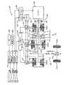
図1は、本発明の一実施例である動力出力装置を搭載したハイブリッド自動車20の構成の概略を示す構成図である。実施例のハイブリッド自動車20は、図示するように、エンジン22と、エンジン22の出力軸としてのクランクシャフト26にダンパ28を介して接続された3軸式の第1動力分配統合機構30および第2動力分配統合機構35と、第1動力分配統合機構30に接続された発電可能なモータMG1と、第1動力分配統合機構30および第2動力分配統合機構35に接続された駆動軸としての駆動軸32aに取り付けられたモータMG2と、第2動力分配統合機構35に取り付けられたモータMG3と、動力出力装置全体をコントロールするハイブリッド用電子制御ユニット70とを備える。
FIG. 1 is a configuration diagram showing an outline of a configuration of a
エンジン22は、ガソリンまたは軽油などの炭化水素系の燃料により動力を出力する内燃機関であり、エンジン22の運転状態を検出する各種センサから信号を入力するエンジン用電子制御ユニット(以下、エンジンECUという)24により燃料噴射制御や点火制御,吸入空気量調節制御などの運転制御を受けている。エンジンECU24は、ハイブリッド用電子制御ユニット70と通信しており、ハイブリッド用電子制御ユニット70からの制御信号によりエンジン22を運転制御すると共に必要に応じてエンジン22の運転状態に関するデータをハイブリッド用電子制御ユニット70に出力する。
The
第1動力分配統合機構30は、外歯歯車のサンギヤ31と、このサンギヤ31と同心円上に配置された内歯歯車のリングギヤ32と、サンギヤ31に噛合すると共にリングギヤ32に噛合する複数のピニオンギヤ33と、複数のピニオンギヤ33を自転かつ公転自在に保持するキャリア34とを備え、サンギヤ31とリングギヤ32とキャリア34とを回転要素として差動作用を行なう遊星歯車機構として構成されている。第1動力分配統合機構30は、キャリア34にはエンジン22のクランクシャフト26が、サンギヤ31にはサンギヤ軸31aを介してモータMG1が、リングギヤ32には駆動軸32aを介してモータMG2がそれぞれ連結されており、モータMG1が発電機として機能するときにはキャリア34から入力されるエンジン22からの動力をサンギヤ31側とリングギヤ32側にそのギヤ比に応じて分配し、モータMG1が電動機として機能するときにはキャリア34から入力されるエンジン22からの動力とサンギヤ31から入力されるモータMG1からの動力を統合してリングギヤ32側に出力する。リングギヤ32に出力された動力は、駆動軸32aからギヤ機構60およびデファレンシャルギヤ62を介して、最終的には車両の駆動輪64a,64bに出力される。
The first power distribution and
第2動力分配統合機構35も第1動力分配統合機構30と同様に、外歯歯車のサンギヤ36と、このサンギヤ36と同心円上に配置された内歯歯車のリングギヤ37と、サンギヤ36に噛合すると共にリングギヤ37に噛合する複数のピニオンギヤ38と、複数のピニオンギヤ33を自転かつ公転自在に保持するキャリア39とを備え、サンギヤ36とリングギヤ37とキャリア39とを回転要素として差動作用を行なう遊星歯車機構として構成されている。第2動力分配統合機構35は、キャリア39には第1動力分配統合機構30のキャリア34が、サンギヤ36には駆動軸32aを介して第1動力分配統合機構30のリングギヤ32およびモータMG2が、リングギヤ37にはモータMG3がそれぞれ連結されており、モータMG3が発電機として機能するときにはキャリア39から入力されるエンジン22からの動力をサンギヤ36側とリングギヤ37側にそのギヤ比に応じて分配し、モータMG3が電動機として機能するときにはキャリア39から入力されるエンジン22からの動力とリングギヤ37から入力されるモータMG3からの動力を統合してサンギヤ36側に出力する。サンギヤ36に出力された動力は、駆動軸32aからギヤ機構60およびデファレンシャルギヤ62を介して、最終的には車両の駆動輪63a,63bに出力される。
Similarly to the first power distribution and
上述したように、第1動力分配統合機構30を用いる場合には、モータMG3からの出力を伴わずに、エンジン22から出力される動力を第1動力分配統合機構30とモータMG1とモータMG2とによってトルク変換して駆動軸32aに出力することができ、第2動力分配統合機構35を用いる場合には、モータMG1からの出力を伴わずに、エンジン22から出力される動力を第2動力分配統合機構35とモータMG2とモータMG3とによってトルク変換して駆動軸32aに出力することができる。これらの場合、バッテリ50からの充放電を伴えば、エンジン22からの動力にバッテリ50からの充放電電力を加えたものをトルク変換して駆動軸32aに出力することができる。この他、モータMG1とモータMG3とからの出力を伴って、エンジン22から出力される動力を第1動力分配統合機構30と第2動力分配統合機構35とモータMG1とモータMG2とモータMG3とによってトルク変換して駆動軸32aに出力することもできる。動力の出力については、後述する。
As described above, when the first power distribution /
モータMG1,MG2,MG3は、いずれも発電機として駆動することができると共に電動機として駆動できる周知の同期発電電動機として構成されており、インバータ41,42,43を介してバッテリ50と電力のやりとりを行なう。インバータ41,42,43とバッテリ50とを接続する電力ライン54は、各インバータ41,42,43が共用する正極母線および負極母線として構成されており、モータMG1,MG2,MG3のいずれかで発電される電力を他のモータで消費することができるようになっている。したがって、バッテリ50は、モータMG1,MG2,MG3のいずれかから生じた電力や不足する電力により充放電されることになる。なお、モータMG1,MG2,MG3により電力収支のバランスをとるものとすれば、バッテリ50は充放電されない。モータMG1,MG2,MG3は、いずれもモータ用電子制御ユニット(以下、モータECUという)40により駆動制御されている。モータECU40には、モータMG1,MG2,MG3を駆動制御するために必要な信号、例えばモータMG1,MG2の回転子の回転位置を検出する回転位置検出センサ44,45,46からの信号や図示しない電流センサにより検出されるモータMG1,MG2,MG3に印加される相電流などが入力されており、モータECU40からは、インバータ41,42,43へのスイッチング制御信号が出力されている。モータECU40は、ハイブリッド用電子制御ユニット70と通信しており、ハイブリッド用電子制御ユニット70からの制御信号によってモータMG1,MG2,MG3を駆動制御すると共に必要に応じてモータMG1,MG2,MG3の運転状態に関するデータをハイブリッド用電子制御ユニット70に出力する。
Each of the motors MG1, MG2, and MG3 is configured as a well-known synchronous generator motor that can be driven as a generator and driven as an electric motor, and exchanges electric power with the
バッテリ50は、バッテリ用電子制御ユニット(以下、バッテリECUという)52によって管理されている。バッテリECU52には、バッテリ50を管理するのに必要な信号、例えば,バッテリ50の端子間に設置された図示しない電圧センサからの端子間電圧,バッテリ50の出力端子に接続された電力ライン54に取り付けられた図示しない電流センサからの充放電電流,バッテリ50に取り付けられた図示しない温度センサからの電池温度などが入力されており、必要に応じてバッテリ50の状態に関するデータを通信によりハイブリッド用電子制御ユニット70に出力する。なお、バッテリECU52では、バッテリ50を管理するために電流センサにより検出された充放電電流の積算値に基づいて残容量(SOC)も演算している。
The
ハイブリッド用電子制御ユニット70は、CPU72を中心とするマイクロプロセッサとして構成されており、CPU72の他に処理プログラムを記憶するROM74と、データを一時的に記憶するRAM76と、図示しない入出力ポートおよび通信ポートとを備える。ハイブリッド用電子制御ユニット70には、イグニッションスイッチ80からのイグニッション信号,シフトレバー81の操作位置を検出するシフトポジションセンサ82からのシフトポジションSP,アクセルペダル83の踏み込み量を検出するアクセルペダルポジションセンサ84からのアクセル開度Acc,ブレーキペダル85の踏み込み量を検出するブレーキペダルポジションセンサ86からのブレーキペダルポジションBP,車速センサ88からの車速Vなどが入力ポートを介して入力されている。ハイブリッド用電子制御ユニット70は、前述したように、エンジンECU24やモータECU40,バッテリECU52と通信ポートを介して接続されており、エンジンECU24やモータECU40,バッテリECU52と各種制御信号やデータのやりとりを行なっている。
The hybrid
こうして構成された実施例のハイブリッド自動車20は、運転者によるアクセルペダル83の踏み込み量に対応するアクセル開度Accと車速Vとに基づいて駆動軸32aに出力すべき要求トルクを計算し、この要求トルクに対応する要求動力が駆動軸32aに出力されるように、エンジン22と3つのモータMG1,MG2,MG3とを運転制御する。エンジン22と3つのモータMG1,MG2,MG3の運転制御としては、エンジン22の運転を停止してモータMG2からの要求動力に見合う動力を駆動軸32aに出力するよう運転制御するモータ運転モード、モータMG3から動力を出力しないようモータMG3を駆動制御し、バッテリ50の充放電なしに或いは充放電を伴って要求動力に見合う動力がエンジン22から出力されるようにエンジン22を運転制御すると共にエンジン22から出力される動力の全部またはその一部が第1動力分配統合機構30と2つのモータMG1,MG2とによってトルク変換されて駆動軸32aに出力されるようモータMG1,MG2を駆動制御するMG1モード、モータMG1から動力を出力しないようモータMG1を駆動制御し、バッテリ50の充放電なしに或いは充放電を伴って要求動力に見合う動力がエンジン22から出力されるようにエンジン22を運転制御すると共にエンジン22から出力される動力の全部またはその一部が第2動力分配統合機構35と2つのモータMG2,MG3とによってトルク変換されて駆動軸32aに出力されるようモータMG2,MG3を駆動制御するMG3モード、バッテリ50の充放電なしに或いは充放電を伴って要求動力に見合う動力がエンジン22から出力されるようにエンジン22を運転制御すると共にエンジン22から出力される動力の全部またはその一部が第1動力分配統合機構30と第2動力分配統合機構35と3つのモータMG1,MG2,MG3とによってトルク変換されて駆動軸32aに出力されるようモータMG1,MG2,MG3を駆動制御する全MGモードなどがある。実施例では、要求動力が比較的小さいときにモータ運転モードにより走行し、通常走行時にMG1モードにより走行し、高速巡航走行時にMG3モードにより走行し、MG1モードとMG3モードとの切り替えの際に全MGモードにより走行する。
The
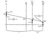
図2は、モータ運転モードにより走行している際の第1動力分配統合機構30および第2動力分配統合機構35の回転要素における回転数とトルクとの力学的な関係を示す共線図である。図中、左から、S1軸は第1動力分配統合機構30のサンギヤ31の回転数(モータMG1の回転数Nm1)を示し、R2軸は第2動力分配統合機構35のリングギヤ37の回転数(モータMG3の回転数Nm3)を示し、C1,C2軸は第1動力分配統合機構30のキャリア34および第2動力分配統合機構35のキャリア39の回転数(エンジン22の回転数Ne)を示し、R1,S2軸は第1動力分配統合機構30のリングギヤ32および第2動力分配統合機構35のサンギヤ36の回転数(モータMG2の回転数Nm2)を示す。また、図中、R1,S2軸の太線矢印は、モータMG2から出力しているトルクTm2を示す。なお、図中、ρ1は第1動力分配統合機構30のギヤ比(サンギヤ31の歯数/リングギヤ32の歯数)を示し、ρ2は第2動力分配統合機構35のギヤ比(サンギヤ36の歯数/リングギヤ37の歯数)を示す。第1動力分配統合機構30のキャリア34とリングギヤ32とが各々第2動力分配統合機構35のキャリア39とサンギヤ36とに接続されているから、図示するように、第1動力分配統合機構30の共線図と第2動力分配統合機構35の共線図は単一のものとして表わすことができる。モータ運転モードでは、エンジン22の運転を停止すると共にモータMG1およびモータMG3からのトルクを出力しない状態でモータMG2から動力を出力して走行する。このとき、第1動力分配統合機構30や第2動力分配統合機構35の特性上、エンジン22やモータMG1,モータMG2は連れ回されて回転することになる。エンジン22,モータMG1,モータMG2のうちいずれが連れ回されて回転するかについては、エネルギが最小となる状態で落ち着くことを考えれば、ポンピングロスやフリクショントルクの大きなエンジン22が回転を停止し、モータMG1とモータMG3とが連れ回されることになる。これが、図2の状態である。実施例のハイブリッド自動車20では、発進時や低速走行時(例えば30km/h以下の車速)に、このモータ運転モードにより走行する。
FIG. 2 is a collinear diagram showing the dynamic relationship between the rotational speed and torque in the rotating elements of the first power
図3はMG1モードにより通常車速(例えば、30〜70km/hの車速)で走行している際の第1動力分配統合機構30および第2動力分配統合機構35の回転要素における回転数とトルクとの力学的な関係を示す共線図であり、図4はMG3モードにより通常車速で走行している際の第1動力分配統合機構30および第2動力分配統合機構35の回転要素における回転数とトルクとの力学的な関係を示す共線図である。図3中、C1,C2軸の太線矢印はエンジン22から出力されるトルクTeを示し、S1軸の2つの太線矢印はエンジン22から出力されるトルクTeによって第1動力分配統合機構30のサンギヤ31に作用するトルクTes1とこのトルクTes1を抑えるためにモータMG1から出力されるトルクTm1を示し、R1,S2軸の2つの太線矢印はエンジン22から出力されるトルクTeによって第1動力分配統合機構30のリングギヤ32(駆動軸32a)に作用するトルクTer1とモータMG1により発電した電力を用いてモータMG2から出力するトルクTm2を示す。図4中、C1,C2軸の太線矢印はエンジン22から出力されるトルクTeを示し、R2軸の2つの太線矢印はエンジン22から出力されるトルクTeによって第2動力分配統合機構35のリングギヤ37に作用するトルクTer2とこのトルクTer2を抑えるためにモータMG3から出力されるトルクTm3を示し、R1,S2軸の2つの太線矢印はエンジン22から出力されるトルクTeによって第2動力分配統合機構35のサンギヤ36(駆動軸32a)に作用するトルクTes2とモータMG3により発電した電力を用いてモータMG2から出力するトルクTm2を示す。
FIG. 3 shows the rotation speed and torque in the rotating elements of the first power
通常車速で走行しているときには、図3および図4に示すように、エンジン22から出力される動力を第1動力分配統合機構30と2つのモータMG1,MG2とによりトルク変換して駆動軸32aに出力するMG1モードと、エンジン22から出力される動力を第2動力分配統合機構35と2つのモータMG2,MG3とによりトルク変換して駆動軸32aに出力するMG3モードと、の2つのモードのいずれでも走行することができる。このとき、エンジン22から出力されるトルクTeによって駆動軸32aに作用するトルク(以下、直達トルクという)は、MG1モードでは次式(1)によってTer1として算出され、MG3モードでは式(2)によってTes2として算出することができる。ここで、ρ1およびρ2は第1動力分配統合機構30および第2動力分配統合機構35のサンギヤの歯数/リングギヤの歯数であることから値1に比して小さいため、Ter1>Tes2の関係を導くことができる。いま、エンジン22を同一の運転ポイント(回転数NeとトルクTeとが同一)により運転し、エンジン22から出力される動力をバッテリ50の充放電なしに駆動軸32aに出力することを考える。このとき、直達トルクはMG1モードの方が大きくなるから、MG1モードでのモータMG1による発電電力はMG3モードでのモータMG3による発電電力より小さくなり、モータMG2から出力するトルクはMG1モードの方が小さくなる。モータ効率を考えれば、発電電力やモータMG2からの出力トルクが小さい方が全体としてのエネルギ効率が高くなるから、いま考えている状態では、MG1モードの方がMG3モードに比してエネルギ効率が高いものとなる。実施例では、こうした理由から、通常車速により走行するときにはMG1モードを選択して走行するのである。
When traveling at a normal vehicle speed, as shown in FIGS. 3 and 4, the power output from the

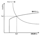
図5はMG1モードにより高速(例えば、70km/h以上の車速)で巡航走行している際の第1動力分配統合機構30および第2動力分配統合機構35の回転要素における回転数とトルクとの力学的な関係を示す共線図であり、図6はMG3モードにより高速で巡航走行している際の第1動力分配統合機構30および第2動力分配統合機構35の回転要素における回転数とトルクとの力学的な関係を示す共線図である。ハイブリッド自動車20が高速で巡航しているときには、エンジン22の運転ポイント(回転数NeとトルクTe)にもよるが、図5および図6のS1軸に示すように、モータMG1は負回転する。MG1モードでは、図5に示すように、エンジン22から出力されるトルクTeによってサンギヤ軸31aに作用するトルクTes1をモータMG1から抑えるように作用させる必要から、モータMG1は力行制御されることになる。エンジン22から出力される動力のすべてをトルク変換する場合を考えれば、モータMG1で消費される電力をモータMG2で賄う必要が生じ、結果として、エンジン22からの動力にモータMG1からの動力を加えて駆動軸32aに出力し、駆動軸32aの動力の一部を用いてモータMG2で発電し、その発電電力をモータMG1に供給することになる。即ち、駆動軸32aに出力された動力が電力に変換されて再び動力として駆動軸32aに出力される動力の循環(以下、動力循環という)が生じることになる。上述したように、モータMG1やモータMG2の効率を考えれば、動力循環はエネルギ効率を低下させる。第1動力分配統合機構30における動力の伝達効率と減速比との関係の一例を図7に示す。図中、減速比が1/(1+ρ1)未満の領域が動力循環の領域である。図示するように、この動力循環の領域では、伝達効率は著しく小さくなる。MG3モードでは、図6に示すように、図4を用いて説明した通常車速で走行しているときと同様に、モータMG3は発電機として動作するから、MG1モードのときのような動力循環はない。実施例では、こうした理由から、高速で巡航走行しているときにはMG3モードを選択して走行するのである。
FIG. 5 shows the rotational speed and torque of the rotating elements of the first power
以上、実施例のハイブリッド自動車20における走行状態と運転モードとエネルギ効率との関係について説明した。次に、実施例のハイブリッド自動車20の動作、特に、走行状態に応じて運転モードを切り替える際の動作について説明する。図8は、実施例のハイブリッド用電子制御ユニット70により実行される駆動制御ルーチンの一例を示すフローチャートである。このルーチンは、モードの切替処理を実行している最中を除いて所定時間毎(例えば、8msec毎)に繰り返し実行される。
In the above, the relationship between the driving state, the driving mode, and the energy efficiency in the
駆動制御ルーチンが実行されると、ハイブリッド用電子制御ユニット70のCPU72は、まず、アクセルペダルポジションセンサ84からのアクセル開度Accや車速センサ88からの車速V,モータMG1,MG2,MG3の回転数Nm1,Nm2,Nm3など制御に必要なデータを入力する処理を実行する(ステップS100)。ここで、モータMG1,MG2,MG3の回転数Nm1,Nm2,Nm3は、回転位置検出センサ44,45,46により検出されるモータMG1,MG2,MG3の回転子の回転位置に基づいて計算されたものをモータECU40から通信により入力するものとした。
When the drive control routine is executed, first, the
こうしてデータを入力すると、入力したアクセル開度Accと車速Vとに基づいて車両に要求されるトルクとして駆動輪63a,63bに連結された駆動軸32aに出力すべき要求トルクT*と車両に要求される要求パワーP*とを設定する(ステップS110)。要求トルクT*は、実施例では、アクセル開度Accと車速Vと要求トルクT*との関係を予め定めて要求トルク設定用マップとしてROM74に記憶しておき、アクセル開度Accと車速Vとが与えられると記憶したマップから対応する要求トルクT*を導出して設定するものとした。図9に要求トルク設定用マップの一例を示す。要求パワーP*は、設定した要求トルクT*に駆動軸32aの回転数としてモータMG2の回転数Nm2を乗じたものにバッテリ50の充放電要求量Pb*とロスとを加えたものとして計算することができる。ここで、充放電要求量Pb*は、バッテリ50の残容量(SOC)やアクセル開度Accなどによって設定することができる。
When the data is input in this way, the required torque T * to be output to the
要求トルクT*と要求パワーP*とを設定すると、設定した要求パワーP*を閾値Prefと比較する(ステップS120)。ここで、閾値Prefは、エンジン22の運転を停止してモータMG2から出力された動力だけで走行するモータ運転モードの範囲を設定するものであり、モータMG2の性能やバッテリ50の容量などにより設定することができる。要求パワーP*が閾値Prefより大きいときには、エンジン22から要求パワーP*を出力するためにエンジン22の目標パワーPe*に要求パワーP*を設定し(ステップS130)、要求パワーP*が閾値Pref以下のときには、モータ運転モードにするためにエンジン22の目標パワーPe*に値0を設定する(ステップS140)。
When the required torque T * and the required power P * are set, the set required power P * is compared with a threshold value Pref (step S120). Here, the threshold value Pref sets the range of the motor operation mode in which the operation of the
目標パワーPe*を設定すると、設定した目標パワーPe*に基づいてエンジン22の目標回転数Ne*と目標トルクTe*とを設定する(ステップS150)。この設定は、目標パワーPe*に要求トルクT*が設定されているときには、エンジン22を効率よく動作させる動作ラインと目標パワーPe*とに基づいて目標回転数Ne*と目標トルクTe*とを設定する。エンジン22の動作ラインの一例と目標回転数Ne*と目標トルクTe*とを設定する様子を図10に示す。図示するように、目標回転数Ne*と目標トルクTe*は、動作ラインと目標パワーPe*(Ne*×Te*)が一定の曲線との交点により求めることができる。一方、目標パワーPe*に値0が設定されているときには、目標回転数Ne*と目標トルクTe*のいずれにも値0が設定される。
When the target power Pe * is set, the target rotational speed Ne * and the target torque Te * of the
こうしてエンジン22の目標回転数Ne*と目標トルクTe*とを設定すると、現在のモータMG1の回転数Nm1と設定された目標トルクTe*とを調べて設定すべき運転モードを判定する(ステップS160)。運転モードは次のように判定される。目標トルクTe*が値0のときには、エンジン22の運転は停止されるから、モータ運転モードと判定する。目標トルクTe*が値0ではなく、モータMG1の回転数Nm1が値0以上(モータMG1が正回転)のときには、MG1モードとMG3モードのうち直達トルクが大きくエネルギ効率のよいMG1モードと判定する。目標トルクTe*が値0ではなく、モータMG1の回転数Nm1が値0未満(モータMG1が負回転)のときには、動力循環のないMG3モードと判定する。
When the target rotational speed Ne * and the target torque Te * of the
いま、停車していた車両が発進し、高速で巡航走行するまでを順次考える。発進時には、前述したように、モータ運転モードで行なわれるからステップS160でもモータ運転モードが判定される。この場合、モータMG1のトルク指令Tm1*とモータMG3のトルク指令Tm3*に値0を設定する(ステップS200,S210)。発進後、通常の車速(例えば、30km/h〜70km/h)で走行しているときには、ステップS160ではMG1モードが判定される。この場合、いままでの運転モードがMG3モードか否かを判定し(ステップS170)、MG3モードのときにはMG1モードへの切替処理を実行する(ステップS180)。いま、発進後の通常の車速を考えているから、いままでの運転モードはモータ運転モードかMG1モードである。MG1モードへの切替処理については後述する。いままでの運転モードがMG3モードではないと判定されると、ステップS150で設定した目標回転数Ne*とモータMG2の回転数Nm2と第1動力分配統合機構30のギヤ比ρ1とを用いて次式(3)によりモータMG1の目標回転数Nm1*を計算すると共に計算した目標回転数Nm1*と現在の回転数Nm1とに基づいて式(4)によりモータMG1のトルク指令Tm1*を計算し(ステップS200)、モータMG3のトルク指令Tm3*に値0を設定する(ステップS210)。ここで、式(3)は、第1動力分配統合機構30の回転要素に対する力学的な関係式であり、図3に例示した共線図から容易に導くことができる。また、式(4)は、モータMG1を目標回転数Nm1*で回転させるためのフィードバック制御における関係式であり、式(4)中、右辺第2項の「k1」は比例項のゲインであり、右辺第3項の「k2」は積分項のゲインである。
Now consider the time from when the stopped vehicle starts to cruise at high speed. At the time of starting, as described above, since the motor operation mode is performed, the motor operation mode is also determined in step S160. In this case, 0 is set to the torque command Tm1 * of the motor MG1 and the torque command Tm3 * of the motor MG3 (steps S200 and S210). When the vehicle is traveling at a normal vehicle speed (for example, 30 km / h to 70 km / h) after starting, the MG1 mode is determined in step S160. In this case, it is determined whether or not the current operation mode is the MG3 mode (step S170). When the operation mode is the MG3 mode, the switching process to the MG1 mode is executed (step S180). Since the normal vehicle speed after starting is considered now, the operation mode so far is the motor operation mode or the MG1 mode. The switching process to the MG1 mode will be described later. If it is determined that the current operation mode is not the MG3 mode, the following is performed using the target rotation speed Ne *, the rotation speed Nm2 of the motor MG2 set in step S150, and the gear ratio ρ1 of the first power distribution and
こうしてモータMG1のトルク指令Tm1*とモータMG3のトルク指令Tm3*とを設定すると、バッテリ50の出力制限Woutと計算したモータMG1のトルク指令Tm1*に現在のモータMG1の回転数Nm1を乗じて得られるモータMG1の消費電力(発電電力)との偏差をモータMG2の回転数Nm2で割ることによりモータMG2から出力してもよいトルクの上限としてのトルク制限Tmaxを次式(5)により計算すると共に(ステップS220)、要求トルクT*とトルク指令Tm1*と第1動力分配統合機構30のギヤ比ρ1を用いてモータMG2から出力すべきトルクとしての仮モータトルクTm2tmpを式(6)により計算し(ステップS230)、計算したトルク制限Tmaxと仮モータトルクTm2tmpとを比較して小さい方をモータMG2のトルク指令Tm2*として設定する(ステップS240)。なお、モータ運転モードでは、モータMG1のトルク指令Tm1*に値0が設定されているから、トルク制限Tmaxにはバッテリ50の出力制限Woutを回転数Nm2で除した値として計算され、仮モータトルクTm2tmpには要求トルクT*が設定されるから、そのいずれか小さい方がモータMG2のトルク指令Tm2*に設定される。このようにモータMG2のトルク指令Tm2*を設定することにより、駆動軸32aに出力する要求トルクT*をバッテリ50の出力制限の範囲内で制限したトルクとして設定することができる。なお、式(6)は、前述した図3の共線図から容易に導き出すことができる。
Thus, when the torque command Tm1 * of the motor MG1 and the torque command Tm3 * of the motor MG3 are set, the output limit Wout of the
こうしてエンジン22の目標回転数Ne*や目標トルクTe*,モータMG1,MG2,MG3のトルク指令Tm1*,Tm2*,Tm3*を設定すると、エンジン22の目標回転数Ne*と目標トルクTe*についてはエンジンECU24に、モータMG1,MG2,MG3のトルク指令Tm1*,Tm2*,Tm3*についてはモータECU40にそれぞれ送信して(ステップS350)、駆動制御ルーチンを終了する。目標回転数Ne*と目標トルクTe*とを受信したエンジンECU24は、エンジン22が目標回転数Ne*と目標トルクTe*とによって示される運転ポイントで運転されるようにエンジン22における燃料噴射制御や点火制御などの制御を行なう。また、トルク指令Tm1*,Tm2*,Tm3*を受信したモータECU40は、トルク指令Tm1*でモータMG1が駆動されると共にトルク指令Tm2*でモータMG2が駆動され、トルク指令Tm3*でモータMG3が駆動されるよう、インバータ41,42,43のスイッチング素子のスイッチング制御を行なう。
When the target rotational speed Ne * and target torque Te * of the
こうした駆動制御により、車両が高速(例えば、70km/h以上)で走行するようになると、ステップS160でMG3モードが判定されると、いままでの運転モードがMG1モードであるか否かを判定し(ステップS270)、MG1モードのときにはMG3モードへの切替処理を実行する(ステップS280)。いま、発進後に車速が高速になった場合を考えているから、いままでの運転モードはMG1モードである。したがって、MG3モードへの切替処理が実行される。MG3モードへの切替処理は、図11に例示する第1切替処理ルーチンにより行なわれる。MG3モードにおける駆動制御を説明する前に、第1切替処理ルーチンによるMG3モードへの切替処理について説明する。なお、実施例では、図8の駆動制御ルーチンは、この第1切替処理ルーチンが実行されている最中には、要求トルクT*と要求パワーP*とを設定するまでの処理(ステップS100およびS110)だけを繰り返し実行し、それ以降の処理は実行しない。したがって、エンジン22は第1切替処理ルーチンが実行される直前に設定された運転ポイント(目標回転数Ne*,目標トルクTe*)で運転されることになる。
With such drive control, when the vehicle travels at a high speed (for example, 70 km / h or more), when the MG3 mode is determined in step S160, it is determined whether or not the current operation mode is the MG1 mode. (Step S270) When in the MG1 mode, a switching process to the MG3 mode is executed (step S280). Since the case where the vehicle speed becomes high after the start is considered, the operation mode so far is the MG1 mode. Therefore, the switching process to the MG3 mode is executed. The switching process to the MG3 mode is performed by a first switching process routine illustrated in FIG. Before describing the drive control in the MG3 mode, the switching process to the MG3 mode by the first switching process routine will be described. In the embodiment, the drive control routine of FIG. 8 performs the processing until the required torque T * and the required power P * are set (step S100 and step S100) while the first switching process routine is being executed. Only S110) is repeatedly executed, and the subsequent processing is not executed. Therefore, the
第1切替処理ルーチンが実行されると、まず、モータMG1,MG2,MG3の回転数Nm1,Nm2,Nm3と要求トルクT*とを読み込む処理を実行する(ステップS400)。そして、前回設定されたトルク指令Tm1*から所定トルクΔT1を加えた値としてモータMG1のトルク指令Tm1*を設定する(ステップS410)。ここで、トルク指令Tm1*は、図3および図5のS1軸の方向とトルクTm1の方向とから解るように、負の値が設定されているから、正の値の所定トルクΔT1を加えることにより、値0に向けて変化することになる。所定トルクΔT1は、トルク指令Tm1*を序変するためのトルクであり、ステップS400〜S450を繰り返し実行する時間間隔やモータMG1の性能,モードの切り替えに許容される時間,モードの切り替えに要求されるスムーズさなどにより決定される。 When the first switching process routine is executed, first, a process of reading the rotational speeds Nm1, Nm2, and Nm3 of the motors MG1, MG2, and MG3 and the required torque T * is executed (step S400). Then, the torque command Tm1 * of the motor MG1 is set as a value obtained by adding the predetermined torque ΔT1 to the previously set torque command Tm1 * (step S410). Here, the torque command Tm1 * is set to a negative value so as to be understood from the direction of the S1 axis and the direction of the torque Tm1 in FIGS. 3 and 5, and therefore, a predetermined torque ΔT1 having a positive value is added. Thus, the value changes toward 0. The predetermined torque ΔT1 is a torque for changing the torque command Tm1 *, and is required for the time interval for repeatedly executing Steps S400 to S450, the performance of the motor MG1, the time allowed for mode switching, and the mode switching. It is determined by smoothness.
続いて、現在設定されている目標回転数Ne*とモータMG2の回転数Nm2と第2動力分配統合機構35のギヤ比ρ2とを用いて次式(7)によりモータMG3の目標回転数Nm3*を計算すると共に計算した目標回転数Nm3*と現在の回転数Nm3とに基づいて式(8)によりモータMG3のトルク指令Tm3*を計算する(ステップS420)。ここで、式(7)は、第2動力分配統合機構35の回転要素に対する力学的な関係式であり、図6に例示した共線図から容易に導くことができる。また、式(8)は、モータMG3を目標回転数Nm3*で回転させるためのフィードバック制御における関係式であり、式(8)中、右辺第2項の「k3」は比例項のゲインであり、右辺第3項の「k4」は積分項のゲインである。
Subsequently, using the currently set target rotational speed Ne *, the rotational speed Nm2 of the motor MG2, and the gear ratio ρ2 of the second power distribution and
こうしてモータMG1のトルク指令Tm1*とモータMG3のトルク指令Tm3*とを設定すると、バッテリ50の出力制限WoutからモータMG1のトルク指令Tm1*に現在のモータMG1の回転数Nm1を乗じて得られるモータMG1の消費電力(発電電力)とモータMG3のトルク指令Tm3*に現在のモータMG3の回転数Nm3を乗じて得られるモータMG3の消費電力(発電電力)とを減じた値をモータMG2の回転数Nm2で割ることによりトルク制限Tmaxを次式(9)により計算すると共に(ステップS430)、要求トルクT*とトルク指令Tm1*と第1動力分配統合機構30のギヤ比ρ1とトルク指令Tm3*と第2動力分配統合機構35のギヤ比ρ2とを用いてモータMG2から出力すべきトルクとしての仮モータトルクTm2tmpを式(10)により計算し(ステップS440)、計算したトルク制限Tmaxと仮モータトルクTm2tmpとを比較して小さい方をモータMG2のトルク指令Tm2*として設定する(ステップS450)。ここで、式(10)は、前述した図5および図6の共線図から容易に導き出すことができる。
When the torque command Tm1 * of the motor MG1 and the torque command Tm3 * of the motor MG3 are thus set, the motor obtained by multiplying the torque command Tm1 * of the motor MG1 by the current rotation speed Nm1 of the motor MG1 from the output limit Wout of the
こうしてモータMG1,MG2,MG3のトルク指令Tm1*,Tm2*,Tm3*を設定すると、設定したトルク指令Tm1*,Tm2*,Tm3*をモータECU40に送信する(ステップS460)。トルク指令Tm1*,Tm2*,Tm3*を受信したモータECU40の動作については説明した。そして、モータMG1のトルク指令Tm1*が値0以上に至ったかを判定し(ステップS470)、トルク指令Tm1*が値0以上に至るまではステップS400に戻ってステップS400〜S470の処理を繰り返し、トルク指令Tm1*が値0以上に至ったときに第1切替処理ルーチンを終了する。即ち、トルク指令Tm1*が値0に至るまで所定トルクΔT1ずつ増加されるのである。第1切替処理ルーチンによりMG1モードからMG3モードに切り替える際のモータMG1,MG2,MG3のトルクTm1,Tm2,Tm3の時間変化の一例を図12に示す。図示するように、第1切替処理ルーチンの実行が開始された時間t1からモータMG1のトルクTm1は値0に向かって変化し、それに伴ってモータMG3のトルクTm3は負の値になり、モータMG2のトルクTm2は負の値から正の値に変化する。そして、モータMG1のトルクTm1が値0に至る時間t2で切り替えが完了する。このように処理することにより、MG1モードからMG3モードにスムーズに切り替えることができる。
When the torque commands Tm1 *, Tm2 *, Tm3 * of the motors MG1, MG2, MG3 are thus set, the set torque commands Tm1 *, Tm2 *, Tm3 * are transmitted to the motor ECU 40 (step S460). The operation of the
こうしてMG1モードからMG3モードへの切り替えが行なわれると、駆動制御ルーチンでは、モータMG1のトルク指令Tm1*に値0を設定すると共に(ステップS300)、上述した式(7)および式(8)を用いてモータMG3の目標回転数Nm3*とトルク指令Tm3*を計算し(ステップS310)、バッテリ50の出力制限WoutとモータMG3のトルク指令Tm3*に現在のモータMG3の回転数Nm3を乗じて得られるモータMG3の消費電力(発電電力)との偏差をモータMG2の回転数Nm2で割ることによりトルク制限Tmaxを次式(11)により計算すると共に(ステップS320)、要求トルクT*とトルク指令Tm3*と第2動力分配統合機構35のギヤ比ρ2とを用いてモータMG2から出力すべきトルクとしての仮モータトルクTm2tmpを式(12)により計算し(ステップS330)、計算したトルク制限Tmaxと仮モータトルクTm2tmpとを比較して小さい方をモータMG2のトルク指令Tm2*として設定する(ステップS340)。ここで、式(12)は、前述した図6の共線図から容易に導き出すことができる。
When switching from the MG1 mode to the MG3 mode is performed in this way, in the drive control routine, the torque command Tm1 * of the motor MG1 is set to 0 (step S300), and the above equations (7) and (8) are set. The target rotational speed Nm3 * and the torque command Tm3 * of the motor MG3 are used to calculate (step S310), and obtained by multiplying the output limit Wout of the
そして、設定したエンジン22の目標回転数Ne*や目標トルクTe*をエンジンECU24に送信すると共にモータMG1,MG2,MG3のトルク指令Tm1*,Tm2*,Tm3*をモータECU40に送信して(ステップS350)、駆動制御ルーチンを終了する。目標回転数Ne*と目標トルクTe*とを受信したエンジンECU24による制御やトルク指令Tm1*,Tm2*,Tm3*を受信したモータECU40による制御については前述した。
Then, the set target rotational speed Ne * and target torque Te * of the
次に、車両が高速巡航走行している状態から通常の車速で走行する状態に移行する際を考える。このとき、駆動制御ルーチンのステップS160ではMG1モードが判定され、ステップS170ではいままでの運転モードとしてMG3モードが判定されるから、MG3モードからMG1モードへの切替処理が実行される(ステップS180)。この切替処理は、図13に例示する第2切替処理ルーチンにより行なわれる。実施例では、第1切替処理ルーチンを実行するときと同様に、駆動制御ルーチンではこの第2切替処理ルーチンが実行されている最中には、要求トルクT*と要求パワーP*とを設定するまでの処理(ステップS100およびS110)だけを繰り返し実行し、それ以降の処理は実行しない。したがって、エンジン22は第2切替処理ルーチンが実行される直前に設定された運転ポイント(目標回転数Ne*,目標トルクTe*)で運転されることになる。
Next, consider a case where the vehicle is moving from a state where the vehicle is traveling at high speed to a state where the vehicle is traveling at a normal vehicle speed. At this time, in step S160 of the drive control routine, the MG1 mode is determined, and in step S170, the MG3 mode is determined as the current operation mode. Therefore, the switching process from the MG3 mode to the MG1 mode is executed (step S180). . This switching process is performed by a second switching process routine illustrated in FIG. In the embodiment, the required torque T * and the required power P * are set during the execution of the second switching process routine in the drive control routine, as in the case of executing the first switching process routine. Only the processes up to (steps S100 and S110) are repeatedly executed, and the subsequent processes are not executed. Therefore, the
第2切替処理ルーチンでは、まず、モータMG1,MG2,MG3の回転数Nm1,Nm2,Nm3と要求トルクT*とを読み込み(ステップS500)。前回設定されたトルク指令Tm3*から所定トルクΔT3を加えた値としてモータMG3のトルク指令Tm3*を設定する(ステップS510)。ここで、トルク指令Tm3*は、図4および図6のR2軸の方向とトルクTm3の方向とから解るように、負の値が設定されているから、正の値の所定トルクΔT3を加えることにより、値0に向けて変化することになる。所定トルクΔT3は、トルク指令Tm3*を序変するためのトルクであり、ステップS500〜S550を繰り返し実行する時間間隔やモータMG3の性能,モードの切り替えに許容される時間,モードの切り替えに要求されるスムーズさなどにより決定される。 In the second switching process routine, first, the rotational speeds Nm1, Nm2, and Nm3 of the motors MG1, MG2, and MG3 and the required torque T * are read (step S500). The torque command Tm3 * of the motor MG3 is set as a value obtained by adding a predetermined torque ΔT3 from the previously set torque command Tm3 * (step S510). Here, the torque command Tm3 * is set to a negative value so as to be understood from the direction of the R2 axis and the direction of the torque Tm3 in FIGS. 4 and 6, and therefore a predetermined torque ΔT3 having a positive value is added. Thus, the value changes toward 0. The predetermined torque ΔT3 is a torque for changing the torque command Tm3 *, and is required for the time interval for repeatedly executing Steps S500 to S550, the performance of the motor MG3, the time allowed for mode switching, and the mode switching. It is determined by smoothness.
次に、上述した式(3)および式(4)によりモータMG1の目標回転数Nm1*とトルク指令Tm1*とを計算する(ステップS520)。続いて、式(9)を用いてトルク制限Tmaxを計算すると共に(ステップS530)、式(10)を用いて仮モータトルクTm2tmpを計算し(ステップS540)、計算したトルク制限Tmaxと仮モータトルクTm2tmpとを比較して小さい方をモータMG2のトルク指令Tm2*として設定する(ステップS550)。そして、設定したトルク指令Tm1*,Tm2*,Tm3*をモータECU40に送信し(ステップS560)、モータMG3のトルク指令Tm3*が値0以上に至ったかを判定し(ステップS570)、トルク指令Tm3*が値0以上に至るまではステップS500に戻ってステップS500〜S570の処理を繰り返し、トルク指令Tm3*が値0以上に至ったときに第2切替処理ルーチンを終了する。したがって、トルク指令Tm3*は値0に至るまで所定トルクΔT3ずつ増加されるのである。第2切替処理ルーチンによりMG3モードからMG1モードに切り替える際のモータMG1,MG2,MG3のトルクTm1,Tm2,Tm3の時間変化の一例を図14に示す。図示するように、第2切替処理ルーチンの実行が開始された時間t3からモータMG3のトルクTm3は値0に向かって変化し、それに伴ってモータMG1のトルクTm1は負の値になり、モータMG2のトルクTm2は直達トルクが小さくなるから正の大きな値から正の小さな値に変化する。そして、モータMG3のトルクTm3が値0に至る時間t4で切り替えが完了する。このように処理することにより、MG3モードからMG2モードにスムーズに切り替えることができる。
Next, the target rotational speed Nm1 * of the motor MG1 and the torque command Tm1 * are calculated by the above-described equations (3) and (4) (step S520). Subsequently, the torque limit Tmax is calculated using the equation (9) (step S530), and the temporary motor torque Tm2tmp is calculated using the equation (10) (step S540). The calculated torque limit Tmax and the temporary motor torque are calculated. Compared with Tm2tmp, the smaller one is set as the torque command Tm2 * of the motor MG2 (step S550). Then, the set torque commands Tm1 *, Tm2 *, Tm3 * are transmitted to the motor ECU 40 (step S560), and it is determined whether the torque command Tm3 * of the motor MG3 has reached a
こうしてMG1モードへの切替処理が終了すると、それ以降はステップS200〜S240の処理によりモータMG1,MG2,MG3のトルク指令Tm1*,Tm2*,Tm3*を設定することになる。これらの処理については詳述した。 When the process for switching to the MG1 mode is thus completed, the torque commands Tm1 *, Tm2 *, and Tm3 * of the motors MG1, MG2, and MG3 are set by the processes in steps S200 to S240 thereafter. These processes have been described in detail.
以上説明した実施例のハイブリッド自動車20によれば、エンジン22と2つの動力分配統合機構30,35と3つのモータMG1,MG2,MG3を用いて駆動軸32aに動力を効率よく出力することができる。即ち、発進時や比較的低車速で走行するときにはモータ運転モードにより走行することにより、エンジン22の効率の悪い運転ポイントでの運転を抑止することにより、通常の車速で走行するときにはMG1モードとしてエンジン22から駆動軸32aに作用させる直達トルクを大きくすることにより、高速で巡航走行するときにはMG3モードとして動力循環を抑止することにより、エネルギ効率の向上を図ることができるのである。しかも、MG1モードとMG3モードとの切り替えの際には、モータMG1のトルク指令Tm1*やモータMG3のトルク指令Tm3*を序変するから、モードの切り替えをスムーズに行なうことができる。また、実施例のハイブリッド自動車20では、クラッチを備えないから、クラッチを備えるものに比して、簡易な構成とすることができる。
According to the
実施例のハイブリッド自動車20では、説明の容易のために、目標トルクTe*が値0であるか否かとモータMG1の回転数Nm1が値0以上であるか否かにより運転モードを判定するものとしたが、頻繁なモードの切り替えを抑止するために、ヒステリシスを持たせるものとしてもよい。即ち、MG1モードからMG3モードへの切り替えは目標トルクTe*が値0より大きくてモータMG1の回転数Nm1が値0より若干小さい負の値となったときに行ない、MG3モードからMG1モードへの切り替えは目標トルクTe*が値0より大きくてモータMG1の回転数Nm1が値0より若干大きな正の値となったときに行なうのである。こうすれば、モードの切り替えが頻繁に生じることを抑止することができる。なお、モータ運転モードからの切り替えやモータ運転モードへの切り替えも同様にヒステリシスを持たせるものとしてもよいのは勿論である。
In the
また、MG3モードでの走行を高速での巡航走行に限定するために、MG1モードからMG3モードへの切り替えを車速Vが所定車速Vref(例えば、70km/h)以上となったことを条件としてもよいし、さらに車速Vが所定車速Vref以上であって所定時間に亘って定常走行していることを条件としてもよい。定常走行しているか否かの判定を車速Vの変化ΔVが所定時間に亘って所定値V1未満であるか否かにより行なう場合の駆動制御ルーチンの一例の一部を図15に示す。図15には、図8のルーチンのステップS160〜S180,ステップS270,S280のモードの切り替えの部分に相当する部分だけを示した。このルーチンでは、車速Vを所定車速Vrefと比較し(ステップS660)、車速Vが所定車速Vref未満のときにはMG1モードとして駆動制御する。車速Vが所定車速Vref以上になったときには所定時間に亘って車速Vの変化ΔVが所定値V1未満か否かを判定し(ステップS690)、所定時間に亘って車速Vの変化ΔVが所定値V1未満でないときにはMG3モードへの切替処理を行なわず、MG1モードのままで駆動制御し、所定時間に亘って車速Vの変化ΔVが所定値V1未満のときにだけMG3モードへの切替処理を実行して、MG3モードとして駆動制御する。また、定常走行しているか否かの判定を要求トルクT*の変化ΔT*が所定時間に亘って所定値T1未満であるか否かにより行なう場合の駆動制御ルーチンの一例の一部を図16に示す。このルーチンでは、図15のルーチンのステップS690を所定時間に亘って要求トルクT*の変化ΔT*が所定値T1未満か否かの判定に変更している。このように、MG3モードによる駆動制御を車速Vが所定車速Vref以上のときに限定することにより、MG3への切り替えやMG1への切り替えが頻繁に生じるのを抑止することができる。また、MG3モードによる駆動制御を、車速Vが所定車速Vref以上であることの他に定常走行していること(所定時間に亘って車速Vの変化ΔVが所定値V1未満や所定時間に亘って要求トルクT*の変化ΔT*が所定値T1未満であることなど)を条件に加えることにより、更に、MG3への切り替えやMG1への切り替えが頻繁に生じるのを抑止することができる。 In addition, in order to limit the traveling in the MG3 mode to the cruise traveling at a high speed, the switching from the MG1 mode to the MG3 mode is performed on the condition that the vehicle speed V is equal to or higher than a predetermined vehicle speed Vref (for example, 70 km / h). Further, it may be a condition that the vehicle speed V is equal to or higher than the predetermined vehicle speed Vref and the vehicle travels constantly for a predetermined time. FIG. 15 shows a part of an example of a drive control routine in which it is determined whether or not the vehicle is traveling in a steady manner based on whether or not the change ΔV of the vehicle speed V is less than a predetermined value V1 over a predetermined time. FIG. 15 shows only a portion corresponding to the mode switching portion of steps S160 to S180, steps S270, and S280 of the routine of FIG. In this routine, the vehicle speed V is compared with a predetermined vehicle speed Vref (step S660), and when the vehicle speed V is less than the predetermined vehicle speed Vref, drive control is performed as the MG1 mode. When the vehicle speed V becomes equal to or higher than the predetermined vehicle speed Vref, it is determined whether or not the change ΔV in the vehicle speed V is less than the predetermined value V1 over a predetermined time (step S690), and the change ΔV in the vehicle speed V over the predetermined time is a predetermined value. When it is not less than V1, the switching process to the MG3 mode is not performed, and the drive control is performed in the MG1 mode, and the switching process to the MG3 mode is executed only when the change ΔV of the vehicle speed V is less than the predetermined value V1 over a predetermined time. Then, drive control is performed as the MG3 mode. FIG. 16 shows a part of an example of a drive control routine in the case where the determination as to whether or not the vehicle is running steady is made based on whether or not the change ΔT * in the required torque T * is less than the predetermined value T1 over a predetermined time. Shown in In this routine, step S690 of the routine of FIG. 15 is changed to determine whether or not the change ΔT * of the required torque T * is less than the predetermined value T1 over a predetermined time. Thus, by limiting the drive control in the MG3 mode when the vehicle speed V is equal to or higher than the predetermined vehicle speed Vref, frequent switching to MG3 and switching to MG1 can be suppressed. In addition, the drive control in the MG3 mode is in steady running in addition to the vehicle speed V being equal to or higher than the predetermined vehicle speed Vref (the change ΔV of the vehicle speed V is less than the predetermined value V1 over a predetermined time or over a predetermined time. By adding the change ΔT * of the required torque T * to less than the predetermined value T1), it is possible to further prevent frequent switching to MG3 and switching to MG1.
実施例のハイブリッド自動車20では、発進時や比較的低車速で走行するときにはモータ運転モードにより走行し、通常の車速で走行するときにはMG1モードにより走行し、高速で巡航走行するときにはMG3モードにより走行するものとしたが、発進時や比較的低車速で走行するときにMG1モードやMG3モードで走行するものとしても構わないし、通常の車速で走行するときにモータ運転モードやMG3モードで走行するものとしても構わないし、高速で巡航走行するときにモータ運転モードやMG1モードで走行するものとしても構わない。如何なる運転モードを選択して走行してもよいのである。さらに、MG1モードとMG3モードの切替処理の際にだけモータMG1,MG2,MG3のすべてを駆動するものとしたが、モードの切替処理以外のときでもモータMG1,MG2,MG3のすべてを駆動するものとしても構わない。
The
実施例のハイブリッド自動車20では、第2動力分配統合機構35のキャリア39にはエンジン22のクランクシャフト26が接続された第1動力分配統合機構30のキャリア34を、サンギヤ36にはモータMG2が接続された駆動軸32aを介して第1動力分配統合機構30のリングギヤ32を、リングギヤ37にはモータMG3を、それぞれ連結したが、第2動力分配統合機構35の3軸のうちの2軸が第1動力分配統合機構30の3軸のうちの2軸に接続されていれば、如何なる接続としてもよい。例えば、図17の変形例のハイブリッド自動車20Bに示すように、第2動力分配統合機構35Bのサンギヤにはエンジン22のクランクシャフト26が接続された第1動力分配統合機構30Bのキャリアを、第2動力分配統合機構35BのリングギヤにはモータMG1が接続された第1動力分配統合機構30Bのサンギヤを、第2動力分配統合機構35BのキャリアにはモータMG3を、それぞれ連結するものとしてもよい。また、図18の変形例のハイブリッド自動車20Cに示すように、第2動力分配統合機構35CのサンギヤにはモータMG1が接続された第1動力分配統合機構30Cのサンギヤを、第2動力分配統合機構35Cのリングギヤにはエンジン22のクランクシャフト26が接続された第1動力分配統合機構30Cのキャリアを、第2動力分配統合機構35CのキャリアにはモータMG3を、それぞれ連結するものとしてもよい。更に、図19の変形例のハイブリッド自動車20Dに示すように、第2動力分配統合機構35DのサンギヤにはモータMG3を、第2動力分配統合機構35DのリングギヤにはモータMG2が接続された第1動力分配統合機構30Dのリングギヤを、第2動力分配統合機構35Dのキャリアにはエンジン22のクランクシャフト26が接続された第1動力分配統合機構30Dのキャリアを、それぞれ連結するものとしてもよい。或いは、図20の変形例のハイブリッド自動車20Eに示すように、ラビニヨ型プラネタリギヤを用いて連結するものとしてもよい。
In the
実施例のハイブリッド自動車20や変形例のハイブリッド自動車20B,20C,20D,20E等では、プラネタリギヤとしての第2動力分配統合機構35,35B,35C,35D,35Eを第1動力分配統合機構30,30B,30C,30D,30Eに連結してモータMG1の駆動制御をモータMG3の駆動制御に置き換えるものとしたが、第1動力分配統合機構の3軸のうちの2軸に連結されて回転する回転軸を有し、この回転軸に取り付けられたモータMG3の駆動制御によりモータMG1の駆動制御を置き換えることができるものであれば、プラネタリギヤに限られず、如何なる構成としてもよい。
In the
以上、本発明の実施の形態について実施例を用いて説明したが、本発明はこうした実施例に何等限定されるものではなく、本発明の要旨を逸脱しない範囲内において、種々なる形態で実施し得ることは勿論である。 The embodiments of the present invention have been described using the embodiments. However, the present invention is not limited to these embodiments, and can be implemented in various forms without departing from the gist of the present invention. Of course you get.
20,20B〜20E ハイブリッド自動車、22 エンジン、24 エンジン用電子制御ユニット(エンジンECU)、26 クランクシャフト、28 ダンパ、30,30B〜30E 第1動力分配統合機構、31 サンギヤ、31a
サンギヤ軸、32 リングギヤ、32a 駆動軸、33 ピニオンギヤ、34
キャリア、35,35B〜35E 第2動力分配統合機構、36 サンギヤ、37 リングギヤ、38 ピニオンギヤ、39 キャリア、40 モータ用電子制御ユニット(モータECU)、41,42,43 インバータ、44,45,46 回転位置検出センサ、50 バッテリ、52 バッテリ用電子制御ユニット(バッテリECU)、54 電力ライン、60 ギヤ機構、62 デファレンシャルギヤ、64a,64b 駆動輪、70 ハイブリッド用電子制御ユニット、72 CPU、74 ROM、76 RAM、80 イグニッションスイッチ、81 シフトレバー、82 シフトポジションセンサ、83 アクセルペダル、84 アクセルペダルポジションセンサ、85 ブレーキペダル、86 ブレーキペダルポジションセンサ、88 車速センサ、MG1,MG2,MG3 モータ。
20, 20B to 20E Hybrid vehicle, 22 engine, 24 engine electronic control unit (engine ECU), 26 crankshaft, 28 damper, 30, 30B to 30E first power distribution and integration mechanism, 31 sun gear, 31a
Sun gear shaft, 32 ring gear, 32a drive shaft, 33 pinion gear, 34
Carrier, 35, 35B to 35E Second power distribution and integration mechanism, 36 sun gear, 37 ring gear, 38 pinion gear, 39 carrier, 40 motor electronic control unit (motor ECU), 41, 42, 43 inverter, 44, 45, 46 rotation Position detection sensor, 50 battery, 52 battery electronic control unit (battery ECU), 54 power line, 60 gear mechanism, 62 differential gear, 64a, 64b driving wheel, 70 hybrid electronic control unit, 72 CPU, 74 ROM, 76 RAM, 80 ignition switch, 81 shift lever, 82 shift position sensor, 83 accelerator pedal, 84 accelerator pedal position sensor, 85 brake pedal, 86 brake pedal position sensor, 88 vehicle speed sensor, MG1, G2, MG3 motor.
Claims (15)
内燃機関と、
前記内燃機関の出力軸と前記駆動軸と第1の回転軸とに接続された3軸を有し、該3軸のうちいずれか2軸に入出力される動力に基づいて残余の軸に動力を入出力する第1の3軸式動力入出力手段と、
前記第1の回転軸に動力を入出力する第1の電動機と、
前記駆動軸に動力を入出力する第2の電動機と、
前記第1の3軸式動力入出力手段が有する3軸のうちのいずれか2軸に連結されて回転する第2の回転軸を有し、前記内燃機関からの動力の少なくとも一部を正回転している前記駆動軸に出力するために前記第1の回転軸の回転を増加させる方向の動力が該第1の回転軸に出力されることになるときに該第1の回転軸に出力される動力の少なくとも一部を前記第2の回転軸の回転を減少させる方向の該第2の回転軸に入出力される動力で置換可能な動力置換手段と、
前記第2の回転軸に動力を入出力する第3の電動機と、
前記第1の電動機と前記第2の電動機と前記第3の電動機のうちいずれの電動機とも電力のやりとりが可能な蓄電手段と、
を備える動力出力装置。 A power output device that outputs power to a drive shaft,
An internal combustion engine;
There are three shafts connected to the output shaft of the internal combustion engine, the drive shaft, and the first rotating shaft, and the remaining shaft is powered based on the power input to and output from any two of the three shafts. A first three-axis power input / output means for inputting / outputting
A first electric motor that inputs and outputs power to the first rotating shaft;
A second electric motor that inputs and outputs power to the drive shaft;
The first three-axis power input / output means has a second rotating shaft that rotates while being connected to any two of the three shafts of the first three-axis power input / output means, and at least a part of the power from the internal combustion engine rotates forward When the power in the direction of increasing the rotation of the first rotating shaft is output to the first rotating shaft to output to the driving shaft, the first rotating shaft is output. Power substitution means capable of substituting at least part of the motive power with power inputted to and outputted from the second rotary shaft in a direction that reduces rotation of the second rotary shaft;
A third electric motor for inputting and outputting power to the second rotating shaft;
Power storage means capable of exchanging power with any of the first motor, the second motor, and the third motor;
A power output device comprising:
内燃機関と、
前記内燃機関の出力軸と前記駆動軸と第1の回転軸とに接続された3軸を有し、該3軸のうちいずれか2軸に入出力される動力に基づいて残余の軸に動力を入出力する第1の3軸式動力入出力手段と、
前記第1の回転軸に動力を入出力する第1の電動機と、
前記駆動軸に動力を入出力する第2の電動機と、
前記第1の3軸式動力出力手段が有する3軸のうちのいずれか2軸と接続された2軸を有し、該2軸と第2の回転軸とからなる3軸のうちいずれか2軸に入出力される動力に基づいて残余の軸に動力を入出力する第2の3軸式動力入出力手段と、
前記第2の回転軸に動力を入出力する第3の電動機と、
前記第1の電動機と前記第2の電動機と前記第3の電動機のうちいずれの電動機とも電力のやりとりが可能な蓄電手段と、
前記内燃機関からの動力の少なくとも一部を正回転している前記駆動軸に出力するために前記第1の電動機が回生駆動されることになるときには該第1の電動機を回生制御すると共に前記第3の電動機から前記第2の回転軸に動力が出力されないよう該第3の電動機を制御する第1の制御を実行し、前記内燃機関からの動力の少なくとも一部を正回転している前記駆動軸に出力するために前記第1の電動機が力行駆動されることになるときには前記第1の電動機から前記第1の回転軸に動力が出力されないよう該第1の電動機を制御すると共に前記第3の電動機を回生制御する第2の制御を実行する制御手段と、
を備える動力出力装置。 A power output device that outputs power to a drive shaft,
An internal combustion engine;
There are three shafts connected to the output shaft of the internal combustion engine, the drive shaft, and the first rotating shaft, and the remaining shaft is powered based on the power input to and output from any two of the three shafts. A first three-axis power input / output means for inputting / outputting
A first electric motor that inputs and outputs power to the first rotating shaft;
A second electric motor that inputs and outputs power to the drive shaft;
The first three-axis power output means has two axes connected to any two of the three axes, and any two of the three axes composed of the two axes and the second rotation axis. Second triaxial power input / output means for inputting / outputting power to the remaining shaft based on power input / output to / from the shaft;
A third electric motor for inputting and outputting power to the second rotating shaft;
Power storage means capable of exchanging power with any of the first motor, the second motor, and the third motor;
When the first electric motor is to be regeneratively driven to output at least part of the power from the internal combustion engine to the drive shaft that is rotating forward, the first electric motor is regeneratively controlled and the first electric motor is regenerated. The first drive for controlling the third electric motor so that no power is output from the third electric motor to the second rotating shaft, and at least a part of the power from the internal combustion engine is rotating forward. When the first electric motor is driven to be driven to output to the shaft, the first electric motor is controlled so that no power is output from the first electric motor to the first rotating shaft, and the third electric motor is controlled. Control means for executing second control for regenerative control of the electric motor;
A power output device comprising:
前記駆動軸の回転数を検出する回転数検出手段を備え、
前記制御手段は、前記回転数検出手段により検出された駆動軸の回転数が所定回転数未満のときには前記内燃機関からの動力の少なくとも一部を正回転している前記駆動軸に出力するために前記第1の電動機が力行駆動されることになるときであっても前記第2の制御を実行せずに前記第1の電動機を力行制御すると共に前記第3の電動機から前記第2の回転軸に動力が出力されないよう該第3の電動機を制御する手段である
動力出力装置。 A power output device according to any one of claims 3 to 5 ,
A rotation speed detecting means for detecting the rotation speed of the drive shaft;
The control means outputs at least part of the power from the internal combustion engine to the drive shaft that is rotating forward when the rotation speed of the drive shaft detected by the rotation speed detection means is less than a predetermined rotation speed. Even when the first motor is driven by power running, the second motor is controlled to power running without executing the second control, and the third motor to the second rotating shaft. A power output device, which is means for controlling the third electric motor so that no power is output to the motor.
操作者の操作に基づいて前記駆動軸に出力すべき要求駆動力を設定する要求駆動力設定手段と、
該設定された要求駆動力に基づいて前記内燃機関の運転ポイントを設定する運転ポイント設定手段と、
を備え、
前記制御手段は、前記設定された運転ポイントで前記内燃機関が運転されると共に前記設定された要求駆動力に応じた動力が前記駆動軸に出力されるよう前記内燃機関と前記第1の電動機と前記第2の電動機と前記第3の電動機とを制御する手段である
動力出力装置。 A power output device according to any one of claims 3 to 8 ,
A driving force demand setting module that sets a required driving force to be output to said drive shaft, based on the operator's operation,
Operating point setting means for setting an operating point of the internal combustion engine based on the set required driving force ;
With
The control means is configured to operate the internal combustion engine at the set operating point and output the power corresponding to the set required driving force to the drive shaft. A power output device which is means for controlling the second electric motor and the third electric motor.
前記回転数検出手段に代えて車速を検出する車速検出手段を備え、
前記制御手段は、前記車速検出手段により検出された車速が所定車速未満のときには前記内燃機関からの動力の少なくとも一部を正回転している前記駆動軸に出力するために前記第1の電動機が力行駆動されることになるときであっても前記第2の制御を実行せずに前記第1の電動機を力行制御すると共に前記第3の電動機から前記第2の回転軸に動力が出力されないよう該第3の電動機を制御する手段である
ハイブリッド自動車。 A hybrid vehicle according to claim 11 according to claim 6 ,
Vehicle speed detection means for detecting the vehicle speed instead of the rotation speed detection means,
The control means, the vehicle speed when the detected vehicle speed is less than a predetermined vehicle speed by detecting means the first electric motor to output to the drive shaft that rotates forward at least a part of power from the internal combustion engine Even when power running is to be performed, the first motor is power running controlled without executing the second control, and power is not output from the third motor to the second rotating shaft. A hybrid vehicle which is means for controlling the third electric motor.
前記内燃機関からの動力の少なくとも一部を正回転している前記駆動軸に出力するために前記第1の電動機が回生駆動されることになるときには該第1の電動機を回生制御すると共に前記第3の電動機から前記第2の回転軸に動力が出力されないよう該第3の電動機を制御し、
前記内燃機関からの動力の少なくとも一部を正回転している前記駆動軸に出力するために前記第1の電動機が力行駆動されることになるときには前記第1の電動機から前記第1の回転軸に動力が出力されないよう該第1の電動機を制御すると共に前記第3の電動機を回生制御する
動力出力装置の制御方法。 The remaining shaft based on the internal combustion engine, and three shafts connected to the output shaft, the drive shaft, and the first rotation shaft of the internal combustion engine, based on the power input to and output from any two of the three shafts A first three-axis power input / output means for inputting / outputting power to / from the first motor, a first motor for inputting / outputting power to / from the first rotating shaft, and a second motor for inputting / outputting power to / from the drive shaft. , Having a second rotating shaft connected to any two of the three shafts of the first three-shaft power input / output means and rotating at least a part of the power from the internal combustion engine When the power in the direction of increasing the rotation of the first rotating shaft is output to the first rotating shaft to output to the driving shaft, the first rotating shaft is output. Motion that is input / output to / from the second rotating shaft in a direction that reduces the rotation of the second rotating shaft. In a power-substituted means substitutable, the third and the electric motor, both one of the motor of the first motor and the second motor and the third motor that inputs and outputs power to a second rotary shaft A power output device comprising a power storage means capable of exchanging electric power,
When the first electric motor is to be regeneratively driven to output at least part of the power from the internal combustion engine to the drive shaft that is rotating forward, the first electric motor is regeneratively controlled and the first electric motor is regenerated. Controlling the third electric motor so that no power is output from the third electric motor to the second rotating shaft,
When the first electric motor is to be driven in order to output at least part of the power from the internal combustion engine to the drive shaft that is rotating in the forward direction, the first rotary shaft is driven from the first electric motor. A control method for a power output apparatus, wherein the first motor is controlled so that no power is output to the power source, and the third motor is regeneratively controlled.
前記内燃機関からの動力の少なくとも一部を正回転している前記駆動軸に出力するために前記第1の電動機が回生駆動されることになるときには該第1の電動機を回生制御すると共に前記第3の電動機から前記第2の回転軸に動力が出力されないよう該第3の電動機を制御し、 When the first electric motor is to be regeneratively driven to output at least part of the power from the internal combustion engine to the drive shaft that is rotating forward, the first electric motor is regeneratively controlled and the first electric motor is regenerated. Controlling the third electric motor so that no power is output from the third electric motor to the second rotating shaft,
前記内燃機関からの動力の少なくとも一部を正回転している前記駆動軸に出力するために前記第1の電動機が力行駆動されることになるときには前記第1の電動機から前記第1の回転軸に動力が出力されないよう該第1の電動機を制御すると共に前記第3の電動機を回生制御する When the first electric motor is to be driven in order to output at least part of the power from the internal combustion engine to the drive shaft that is rotating in the forward direction, the first rotary shaft is driven from the first electric motor. The first motor is controlled so that no power is output to the motor, and the third motor is regeneratively controlled.
動力出力装置の制御方法。 Control method of power output device.
Priority Applications (1)
| Application Number | Priority Date | Filing Date | Title |
|---|---|---|---|
| JP2007044063A JP4055819B2 (en) | 2007-02-23 | 2007-02-23 | POWER OUTPUT DEVICE, ITS CONTROL METHOD, AND HYBRID VEHICLE |
Applications Claiming Priority (1)
| Application Number | Priority Date | Filing Date | Title |
|---|---|---|---|
| JP2007044063A JP4055819B2 (en) | 2007-02-23 | 2007-02-23 | POWER OUTPUT DEVICE, ITS CONTROL METHOD, AND HYBRID VEHICLE |
Related Parent Applications (1)
| Application Number | Title | Priority Date | Filing Date |
|---|---|---|---|
| JP2003167067A Division JP3948434B2 (en) | 2003-06-11 | 2003-06-11 | POWER OUTPUT DEVICE, ITS CONTROL METHOD, AND HYBRID VEHICLE |
Publications (2)
| Publication Number | Publication Date |
|---|---|
| JP2007186201A JP2007186201A (en) | 2007-07-26 |
| JP4055819B2 true JP4055819B2 (en) | 2008-03-05 |
Family
ID=38341643
Family Applications (1)
| Application Number | Title | Priority Date | Filing Date |
|---|---|---|---|
| JP2007044063A Expired - Fee Related JP4055819B2 (en) | 2007-02-23 | 2007-02-23 | POWER OUTPUT DEVICE, ITS CONTROL METHOD, AND HYBRID VEHICLE |
Country Status (1)
| Country | Link |
|---|---|
| JP (1) | JP4055819B2 (en) |
Families Citing this family (1)
| Publication number | Priority date | Publication date | Assignee | Title |
|---|---|---|---|---|
| KR101171771B1 (en) | 2006-02-06 | 2012-08-07 | 현대자동차주식회사 | Dual Mode Power Transmission Equipment for Hybrid Electric Vehicle |
-
2007
- 2007-02-23 JP JP2007044063A patent/JP4055819B2/en not_active Expired - Fee Related
Also Published As
| Publication number | Publication date |
|---|---|
| JP2007186201A (en) | 2007-07-26 |
Similar Documents
| Publication | Publication Date | Title |
|---|---|---|
| JP4038183B2 (en) | Power output device, automobile equipped with the same, and power transmission device | |
| JP4345824B2 (en) | Vehicle and control method thereof | |
| JP4321530B2 (en) | Vehicle and control method thereof | |
| JP4312240B2 (en) | VEHICLE, DRIVE DEVICE, AND CONTROL METHOD THEREOF | |
| JP4888154B2 (en) | Vehicle and control method thereof | |
| JP2005295691A (en) | Power output unit and automobile mounting it | |
| JP4229105B2 (en) | Hybrid vehicle and control method thereof | |
| JP4258508B2 (en) | Hybrid vehicle and control method thereof | |
| JP4086042B2 (en) | Automobile and control method thereof | |
| JP4088574B2 (en) | Power output device and automobile equipped with the same | |
| JP2009248732A (en) | Hybrid vehicle and method of controlling the same | |
| JP4297108B2 (en) | Vehicle and control method thereof | |
| JP2009137401A (en) | Hybrid vehicle and control method thereof | |
| JP4217234B2 (en) | POWER OUTPUT DEVICE, AUTOMOBILE MOUNTING THE SAME, DRIVE DEVICE, AND CONTROL METHOD FOR POWER OUTPUT DEVICE | |
| JP2006321458A (en) | Power output device, vehicle mounted with the same, and control method therefor | |
| JP2010195255A (en) | Hybrid vehicle and control method thereof | |
| JP2007112291A (en) | Power output device, vehicle loading it and control method for power output device | |
| JP3948434B2 (en) | POWER OUTPUT DEVICE, ITS CONTROL METHOD, AND HYBRID VEHICLE | |
| JP4345765B2 (en) | Vehicle and control method thereof | |
| JP4031744B2 (en) | Power output device and automobile equipped with the same | |
| JP2005210841A (en) | Vehicle and method for controlling the same | |
| JP2009149154A (en) | Vehicle and control method therefor | |
| JP4055819B2 (en) | POWER OUTPUT DEVICE, ITS CONTROL METHOD, AND HYBRID VEHICLE | |
| JP4291824B2 (en) | Power output apparatus, automobile equipped with the same, and control method of power output apparatus | |
| JP2009262866A (en) | Hybrid car and control method therefor |
Legal Events
| Date | Code | Title | Description |
|---|---|---|---|
| TRDD | Decision of grant or rejection written | ||
| A01 | Written decision to grant a patent or to grant a registration (utility model) |
Free format text: JAPANESE INTERMEDIATE CODE: A01 Effective date: 20071120 |
|
| A61 | First payment of annual fees (during grant procedure) |
Free format text: JAPANESE INTERMEDIATE CODE: A61 Effective date: 20071203 |
|
| FPAY | Renewal fee payment (event date is renewal date of database) |
Free format text: PAYMENT UNTIL: 20101221 Year of fee payment: 3 |
|
| LAPS | Cancellation because of no payment of annual fees |