JP4053426B2 - Marker pen - Google Patents
Marker pen Download PDFInfo
- Publication number
- JP4053426B2 JP4053426B2 JP2002564138A JP2002564138A JP4053426B2 JP 4053426 B2 JP4053426 B2 JP 4053426B2 JP 2002564138 A JP2002564138 A JP 2002564138A JP 2002564138 A JP2002564138 A JP 2002564138A JP 4053426 B2 JP4053426 B2 JP 4053426B2
- Authority
- JP
- Japan
- Prior art keywords
- nib
- pen
- fluid
- marker pen
- marker
- Prior art date
- Legal status (The legal status is an assumption and is not a legal conclusion. Google has not performed a legal analysis and makes no representation as to the accuracy of the status listed.)
- Expired - Fee Related
Links
- 239000003550 marker Substances 0.000 title claims description 66
- 239000012530 fluid Substances 0.000 claims description 60
- 239000000975 dye Substances 0.000 claims description 28
- 239000000463 material Substances 0.000 claims description 27
- 239000011148 porous material Substances 0.000 claims description 10
- 239000002904 solvent Substances 0.000 claims description 6
- 239000000986 disperse dye Substances 0.000 claims description 5
- 239000002250 absorbent Substances 0.000 claims description 3
- 230000002745 absorbent Effects 0.000 claims description 3
- 239000007787 solid Substances 0.000 claims description 2
- 239000004033 plastic Substances 0.000 description 14
- 230000000694 effects Effects 0.000 description 9
- 239000002657 fibrous material Substances 0.000 description 8
- XLYOFNOQVPJJNP-UHFFFAOYSA-N water Substances O XLYOFNOQVPJJNP-UHFFFAOYSA-N 0.000 description 8
- NJPPVKZQTLUDBO-UHFFFAOYSA-N novaluron Chemical compound C1=C(Cl)C(OC(F)(F)C(OC(F)(F)F)F)=CC=C1NC(=O)NC(=O)C1=C(F)C=CC=C1F NJPPVKZQTLUDBO-UHFFFAOYSA-N 0.000 description 6
- 239000003086 colorant Substances 0.000 description 5
- 239000007788 liquid Substances 0.000 description 4
- 239000000049 pigment Substances 0.000 description 4
- 239000002253 acid Substances 0.000 description 3
- 239000002696 acid base indicator Substances 0.000 description 2
- 230000002378 acidificating effect Effects 0.000 description 2
- -1 aromatic organic compounds Chemical class 0.000 description 2
- 238000006243 chemical reaction Methods 0.000 description 2
- 230000006378 damage Effects 0.000 description 2
- 239000002184 metal Substances 0.000 description 2
- 238000000034 method Methods 0.000 description 2
- 239000008188 pellet Substances 0.000 description 2
- 230000005855 radiation Effects 0.000 description 2
- QTBSBXVTEAMEQO-UHFFFAOYSA-M Acetate Chemical compound CC([O-])=O QTBSBXVTEAMEQO-UHFFFAOYSA-M 0.000 description 1
- 208000004547 Hallucinations Diseases 0.000 description 1
- 239000007844 bleaching agent Substances 0.000 description 1
- 239000000919 ceramic Substances 0.000 description 1
- 229910010293 ceramic material Inorganic materials 0.000 description 1
- 239000011248 coating agent Substances 0.000 description 1
- 238000000576 coating method Methods 0.000 description 1
- 230000000295 complement effect Effects 0.000 description 1
- 150000001875 compounds Chemical class 0.000 description 1
- 238000011109 contamination Methods 0.000 description 1
- 238000007796 conventional method Methods 0.000 description 1
- 238000012864 cross contamination Methods 0.000 description 1
- 238000010586 diagram Methods 0.000 description 1
- 230000005670 electromagnetic radiation Effects 0.000 description 1
- 238000005516 engineering process Methods 0.000 description 1
- 239000004794 expanded polystyrene Substances 0.000 description 1
- 239000006260 foam Substances 0.000 description 1
- 239000006261 foam material Substances 0.000 description 1
- 238000012986 modification Methods 0.000 description 1
- 230000004048 modification Effects 0.000 description 1
- 238000000465 moulding Methods 0.000 description 1
- 210000002445 nipple Anatomy 0.000 description 1
- 239000007800 oxidant agent Substances 0.000 description 1
- 229920000642 polymer Polymers 0.000 description 1
- 238000003825 pressing Methods 0.000 description 1
- 238000010791 quenching Methods 0.000 description 1
- 230000000171 quenching effect Effects 0.000 description 1
- 238000001228 spectrum Methods 0.000 description 1
- 239000007921 spray Substances 0.000 description 1
- 229910001220 stainless steel Inorganic materials 0.000 description 1
- 239000010935 stainless steel Substances 0.000 description 1
- 239000000126 substance Substances 0.000 description 1
- 229920001169 thermoplastic Polymers 0.000 description 1
- 239000010409 thin film Substances 0.000 description 1
Images


Classifications
-
- B—PERFORMING OPERATIONS; TRANSPORTING
- B43—WRITING OR DRAWING IMPLEMENTS; BUREAU ACCESSORIES
- B43K—IMPLEMENTS FOR WRITING OR DRAWING
- B43K27/00—Multiple-point writing implements, e.g. multicolour; Combinations of writing implements
- B43K27/08—Combinations of pens
-
- B—PERFORMING OPERATIONS; TRANSPORTING
- B43—WRITING OR DRAWING IMPLEMENTS; BUREAU ACCESSORIES
- B43K—IMPLEMENTS FOR WRITING OR DRAWING
- B43K17/00—Continuously-adjustable nibs, e.g. for drawing-pens; Holders therefor
- B43K17/005—Continuously-adjustable nibs, e.g. for drawing-pens; Holders therefor continuously-adjustable nibs
Description
本発明は、マーカーペンに関するものである。 The present invention relates to a marker pen.
一般的なマーカーペンは、繊維状のフェルトのようなペン先を有する管状のハウジングを備えており、そのペン先が、液体吸収性の芯を介して有色染料を有する水性インクのような指示薬を含んだ内部液貯めに接続されている。このマーカーペンが使用されると、繊維状のペン先には、毛管作用によって液貯めから芯を介してペン先へと伝わるインクが補充される。このようなペンはよく知られているとともに、とりわけ紙あるいは類似の素材上の文章にマークを付けたり色彩効果を生じさせるために使用されている。知られているように、マーカーペンは、1つの色の1つの線を描くために使用される。異なる色の複数の隣接する線を描くためには、2つあるいはそれ以上のペンが必要となる。 A typical marker pen is provided with a tubular housing having a nib such as a fibrous felt, and the nib has an indicator such as an aqueous ink having a colored dye through a liquid-absorbing core. Connected to contained internal fluid reservoir. When this marker pen is used, the fibrous pen nib is replenished with ink transmitted from the liquid reservoir to the nib through the lead by capillary action. Such pens are well known and are used, among other things, to mark text on paper or similar material and to produce color effects. As is known, a marker pen is used to draw one line of one color. To draw multiple adjacent lines of different colors, two or more pens are required.
染料を有する水性インクが表面に塗布されたときに色を変化させたり、水性インク内に存在する染料の色を消去するための流体もまたよく知られている。 Fluids are also well known for changing color when a water-based ink having a dye is applied to a surface, or for erasing the color of a dye present in the water-based ink.
定義上、染料は、非局在化電子系(delocalised electron systems)を有する芳香族有機化合物とされており、さまざまな波長の電磁放射線を吸収する。染料の色は、それぞれの染料内の発色基(chromophore)の存在によってもたらされている。発色基は、染料の非局在化電子雲のエネルギーを変えるような原子配置をとっており、その結果、化合物がスペクトルの可視域から放射線を吸収することによって発色する。 By definition, dyes are aromatic organic compounds with delocalized electron systems and absorb electromagnetic radiation of various wavelengths. The color of the dye is brought about by the presence of a chromophore within each dye. The chromophore has an atomic arrangement that changes the energy of the delocalized electron cloud of the dye, and as a result, the compound develops color by absorbing radiation from the visible region of the spectrum.
酸塩基指示薬は、それ自身が弱酸及び弱塩基とされる染料であり、その共役酸及び共役塩基の形態が異なる色を有している。酸と塩基との間の形態の転化は、指示薬のpHを変化させることによって得られる。 The acid-base indicator itself is a dye that is made into a weak acid and a weak base, and has a color in which the forms of the conjugate acid and the conjugate base are different. Conversion of the form between acid and base is obtained by changing the pH of the indicator.
酸塩基指示薬が染料として例えば紙シートの上に塗布されたとき、及び、酸性あるいは塩基性薬品が実質的に染料のpHを変えるように塗布されたとき、染料の酸性と塩基性との間の形態の転移が、各発色基の変化あるいは破壊をもたらす。この破壊により、本来染料に吸収されていた放射線/光の波長を、可視域の外(色の消去)の値や、他の色の可視域の内(色の変化)の値へと変化させることができる。 When an acid-base indicator is applied as a dye, for example on a paper sheet, and when an acidic or basic chemical is applied so as to substantially change the pH of the dye, between the acidic and basic of the dye The change in form results in a change or destruction of each chromophore. This destruction changes the radiation / light wavelength originally absorbed by the dye to a value outside the visible range (color erasure) or to a value within the visible range of other colors (color change). be able to.
透明あるいは半透明の強調インクを消去あるいは除去するための塗布具が特許文献1に開示されている。この塗布具は、容器と、強調インクのために容器内に含まれる液体漂白剤あるいは液体酸化剤と、容器の一方の端部に設けられ、フェルト性の先端、ローラー、加圧スプレーノズルあるいはハンドポンプのような、除去剤の薄膜を強調インクに塗布する手段であって、下にあるインクあるいは既に強調された印刷素材に対して実質的に影響を及ぼすことなく強調インクの消去あるいは除去効果をもたらす手段とを備えている。そのような塗布具は、別体のマーカーペンによって塗られたインクや染料を消去するために用いられる。 Patent Document 1 discloses an applicator for erasing or removing transparent or translucent emphasis ink. This applicator is provided at one end of the container, a liquid bleach or liquid oxidizer contained in the container for the emphasis ink, a felt tip, roller, pressurized spray nozzle or hand. A means, such as a pump, for applying a thin film of a remover to an emphasized ink that has an effect of erasing or removing the emphasized ink without substantially affecting the underlying ink or the already highlighted print material. Means to bring. Such an applicator is used to erase ink or dye applied by a separate marker pen.
一方の端部に、芯を通してインク液貯めに接続される筆記ペン先が設けられ、他方の端部に、先端に接続されるフェルト、繊維状部材あるいは多孔性部材からなる消去部材が設けられた塗布具が特許文献2に開示されている。この明細書に開示された塗布具の構成では、消去が要求されるときには通常の筆記作用の状態と逆のものとされる。 A writing pen tip connected to the ink reservoir through the core is provided at one end, and an erasing member made of felt, a fibrous member, or a porous member connected to the tip is provided at the other end. An applicator is disclosed in Patent Document 2. In the configuration of the applicator disclosed in this specification, when erasing is required, it is the reverse of the normal writing action state.
特許文献3は、消去部材を含んだボールペンを開示している。この消去部材はペンの一方の端部に配置され、ボールポイントがペンの他方の端部に配置されている。もし、書き損じた場合には、ペンが逆にされ、インクを中和するために消去部材が用いられる。 Patent Document 3 discloses a ballpoint pen including an erasing member. The erasing member is disposed at one end of the pen, and the ball point is disposed at the other end of the pen. If the writing is missed, the pen is reversed and the erasing member is used to neutralize the ink.
マーカーハウジングの同一端部から突出する2つあるいはそれ以上のマーカーペン先を有し、フェルトの先端を備えたマーカーペンは知られている。
本発明の目的は、1工程で、1つの色を有する縞(stripe)とともに、この縞の境界同士の間に1つあるいは複数の他の色を有する1つあるいは複数の線を描くことができ、この1つあるいは複数の線が色の変化あるいは混合技術によって描かれるようにすることができるマーカーペンを提供することである。本発明の他の目的は、1工程で、1つの色を有する縞とともに、この縞の境界同士の間に1つあるいは複数の透明な線を描くことができるマーカーペンを提供することである。縞及び線が1工程で描かれることため、筆記面に塗布されたときに縞及び線の両方が湿っていることになり、これら縞及び線の縁において混合が生じる。 The object of the present invention is to draw one or more lines having one or more other colors between the stripe boundaries with a stripe having one color in one step. It is to provide a marker pen in which the one or more lines can be drawn by a color change or mixing technique. Another object of the present invention is to provide a marker pen capable of drawing one or a plurality of transparent lines between the stripe boundaries together with the stripe having one color in one step. Because the stripes and lines are drawn in one step, both the stripes and lines are wet when applied to the writing surface, and mixing occurs at the edges of these stripes and lines.
本発明のさらなる目的は、筆記面上のマーカーペンの移動方向に関係なく、1工程で、1つの色を有する縞とともに、この縞の境界同士の間に他の色あるいは無色の線を描くことができるマーカーペンを提供することである。この目的は、一方のペン先が他方のペン先に対して略中央に配置されることによって達成される。 A further object of the present invention is to draw a stripe having one color and another color or a colorless line between the borders of the stripe in one step regardless of the moving direction of the marker pen on the writing surface. Is to provide a marker pen. This object is achieved by the fact that one nib is arranged approximately centrally with respect to the other nib.
一方の観点において、本発明は、管状のハウジングと、前記ハウジングの一方の端部から突出する第1の流体保持ペン先と、前記ハウジングの前記一方の端部から突出する第2の流体保持ペン先とを備え、前記ペン先のうちの一方の表面が他方から隔てられ、前記第1のペン先が縞を描くような配置及び寸法とされ、前記第2のペン先が前記縞の境界同士の間に1つあるいは複数の線を描くような配置及び寸法とされているマーカーペンを提供する。 In one aspect, the present invention provides a tubular housing, a first fluid holding pen tip protruding from one end of the housing, and a second fluid holding pen protruding from the one end of the housing. A tip of the nib is separated from the other, the first nib is arranged and dimensioned to draw a stripe, and the second nib is bordered between the stripes. A marker pen is provided that is sized and arranged to draw one or more lines in between.
他方の観点において、本発明は、管状のハウジングであって、該ハウジング内に配置された第1のチャンバー内に存在する流体が補充される第1の流体保持ペン先を一方の端部から突出させた管状のハウジングと、前記ハウジングの前記一方の端部から突出するとともに、前記ハウジング内に配置された第2のチャンバー内に存在する流体が補充される第2の流体保持ペン先とを備え、前記突出するペン先のうちの一方が他方から離間させられているマーカーペンを提供する。 In another aspect, the present invention is a tubular housing that projects from one end a first fluid holding nib that is replenished with a fluid present in a first chamber disposed within the housing. And a second fluid holding nib that protrudes from the one end of the housing and is replenished with fluid existing in a second chamber disposed in the housing. A marker pen is provided in which one of the protruding pen tips is spaced from the other.
前記第1のペン先は、多孔性素材から構成されていることが好ましい。前記第2のペン先もまた、多孔性素材から構成されていてもよい。他には、前記第2のペン先が、毛管通路の設けられた不透過性素材の薄肉チューブ、あるいは、多孔性の流体保持素材を収容する不透過性素材の薄肉チューブを備えていてもよい。前記流体保持素材が、繊維状素材の集合体、スポンジ、あるいは、相対的に固い多孔性素材を備えていてもよい。 The first nib is preferably made of a porous material. The second nib may also be made of a porous material. Alternatively, the second nib may include a thin tube of an impermeable material provided with a capillary passage, or a thin tube of an impermeable material containing a porous fluid holding material. . The fluid holding material may include an aggregate of fibrous materials, a sponge, or a relatively hard porous material.
前記第1のペン先に、前記第2のペン先の少なくとも一部分が突出することが可能な開口部が設けられていてもよい。このとき、前記第1のペン先が、該ペン先の長さ方向の軸線に対して垂直な平面内で環状あるいはリング形状とされていてもよい。前記第1のペン先の側面が、前記長さ方向の軸線に対して略平行とされていてもよいし、これに代えて、前記ペン先の末端部での直径が、該ペン先のハウジングに取り囲まれた端部での直径よりも小さくてもよい。ここで、前記第1のペン先が、一方の端部から他方まで通過する中央孔を有する略部分円錐とされていてもよい。前記第1のペン先の末端部が、例えば先細りではなく、略平坦とされていてもよい。しかしながら、他の形状のペン先が用いられてもよい。例えば、前記第1のペン先の外部輪郭が、横断面で、長円、正方形あるいは矩形とされていてもよいし、それどころか、他の適当ないかなる形状とされていてもよい。 The first nib may be provided with an opening through which at least a part of the second nib can protrude. At this time, the first nib may have an annular shape or a ring shape in a plane perpendicular to the longitudinal axis of the nib. The side surface of the first nib may be substantially parallel to the longitudinal axis. Alternatively, the diameter at the end of the nib is the housing of the nib. It may be smaller than the diameter at the end surrounded by. Here, the first nib may be a substantially partial cone having a central hole that passes from one end to the other. The end of the first nib may be substantially flat, for example, not tapered. However, other shapes of pen nibs may be used. For example, the outer contour of the first nib may be oval, square, or rectangular in cross section, or on the contrary, any other suitable shape.
前記第1のペン先が、吸収性素材からなる分離した複数の部分から成る略環状の配列を備え、前記第2のペン先の少なくとも一部分が、この環状の配列によって形成される孔を通して突出するよう構成してもよい。このとき、第1のペン先の個々の部分が、ハウジングの第1のチャンバーからの流体を受け取るように接続されていてもよい。 The first nib comprises a generally annular array of separated portions of absorbent material, and at least a portion of the second nib projects through a hole formed by the annular array. You may comprise. At this time, individual portions of the first nib may be connected to receive fluid from the first chamber of the housing.
前記第1のペン先の末端部の外表面は相対的に固く、このため該末端部は曲がらないことが好ましく、素材POREXを備えていてもよい。これは、紙、カードあるいは類似の素材の表面に接触させられたときでも、その形状を維持するような多孔性の流体保持物質である。このとき、前記第1のペン先の末端部の少なくとも一部分が、フェルト素材あるいは発泡体素材、例えば発泡ポリスチレンから構成されていてもよい。 It said first outer surface of the nib end piece relative to hard, Therefore preferably does not bend the said distal end may be provided with a material POREX. This is a porous fluid retention material that maintains its shape even when contacted with the surface of paper, card or similar material. At this time, at least a part of the end portion of the first nib may be made of a felt material or a foam material, for example, expanded polystyrene.
前記第1のペン先が、芯を通して前記第1のチャンバーからの流体を受け取るように接続されていてもよい。前記第1のチャンバーが、一般にトランゾーブ(transorb)を備えていてもよい。トランゾーブは、実質的に、不透過性の鞘内に配置された多量の流体保持繊維状物質を備えている。鞘は、一般に両端部に開口させられており、トランゾーブ内に存在する流体を毛管作用によってマーカーペンのペン先へと通過させるための芯を受け止めている。 The first nib may be connected to receive fluid from the first chamber through a wick. The first chamber may generally comprise a transorb. The transorb comprises a substantial amount of fluid retaining fibrous material disposed within a substantially impermeable sheath. The sheath is generally opened at both ends, and receives a core for allowing fluid existing in the transorb to pass through the tip of the marker pen by capillary action.
前記第1のチャンバーが、横断面で、前記ハウジングの内壁に近接あるいは接触するような外壁を有する管状とされていてもよい。 The first chamber may have a cross-sectional shape having a tubular shape having an outer wall that is close to or in contact with the inner wall of the housing.
前記第1のチャンバー内に存在する前記流体が、例えば、有色染料、分散色素あるいは他の有色媒体、使用されたときにインク内の染料あるいは分散色素と化学的に反応する消去素材の溶液、あるいは、前記第1のペン先によって塗布された有色媒体の色を消去したり変化させたりする他の有色媒体を有する水性インクを含んだ指示薬を備えていてもよい。 The fluid present in the first chamber is, for example, a colored dye, disperse dye or other colored medium, a solution of an erasing material that chemically reacts with the dye or disperse dye in the ink when used, or The indicator may contain an aqueous ink having another colored medium that erases or changes the color of the colored medium applied by the first nib.
前記第2のペン先の末端部が、略先細りとされててもよいし、前記ペン先の横断面が、円形とされていてもよい。しかしながら、長円、正方形あるいは矩形のような他の横断面が用いられてもよい。 The end portion of the second nib may be substantially tapered, or the cross section of the nib may be circular. However, other cross sections such as oval, square or rectangular may be used.
前記第2のペン先が、芯を通して前記第2のチャンバーからの流体を受け取るように接続されていてもよい。前記第2のチャンバーが、トランゾーブ(transorb)を備えていてもよい。前記第2のチャンバーが、横断面で、前記環状の第1のチャンバー内の内表面に近接あるいは接触するような外壁を有する管状とされていてもよい。他には、前記第2のチャンバーが、前記ハウジング内に前記第1のチャンバーと並んで配置されていてもよい。 The second nib may be connected to receive fluid from the second chamber through a wick. The second chamber may comprise a transorb. The second chamber may be formed in a tubular shape having an outer wall that is close to or in contact with the inner surface of the annular first chamber in cross section. Alternatively, the second chamber may be arranged in the housing alongside the first chamber.
前記第2のチャンバー内に存在する前記流体が、有色染料、分散色素あるいは他の有色媒体、使用されたときにインク内の有色染料あるいは分散色素と化学的に反応する消去素材の溶剤、あるいは、前記第1のペン先によって散布された有色媒体の色を消去したり変化させたりする他の有色媒体を有する水性インクのような指示薬を備えていてもよい。 The fluid present in the second chamber is, colored dyes, dispersed pigments or other colored media, the ink in the colored dye or disperse dye and-chemical reaction for erasing the material solvent in when it is used or, An indicator such as a water-based ink having another colored medium that erases or changes the color of the colored medium dispersed by the first nib may be provided.
以下、添付した概略図を参照しながら、本発明をその一例によって詳細に記述していく。 Hereinafter, the present invention will be described in detail by way of example with reference to the accompanying schematic drawings.
各実施例において、同一の参照数字は、同一あるいは類似の構成に用いられている。 In each embodiment, the same reference numerals are used for the same or similar configurations.
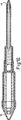
図1に示されるマーカーペンは、細長い中空で略管状をなすアウターケーシング1を備えており、このアウターケーシング1は一般にプラスチック素材から構成されている。しかしながら、他の素材を用いることもできる。ケーシング1の一方の端部は、このケーシングの一方の開口端部内に固く嵌合するような寸法の栓2によって閉塞されている。栓2は一般にプラスチック素材から構成されており、この栓2には近接するケーシングの縁に対して接触する環状の肩部3が設けられている。管状のフェルール4が、一部ケーシング内に設けられて栓2から離れる方向に延びている。フェルールはケーシング1の開口端部に摩擦嵌合しており、このフェルールには近接するケーシングの縁に対して接触するように屹立する環状の肩部5が設けられている。ケーシング1から離れたフェルール4の一部分は、略部分円錐長さ6と略均一な横断面の端部部分7とを有している。このフェルールもまたプラスチック素材から構成されていてもよい。
The marker pen shown in FIG. 1 includes an outer casing 1 that is elongated and hollow and has a substantially tubular shape. The outer casing 1 is generally made of a plastic material. However, other materials can be used. One end of the casing 1 is closed by a plug 2 that is dimensioned to fit tightly within one open end of the casing. The plug 2 is generally made of a plastic material, and the plug 2 is provided with an annular shoulder portion 3 that comes into contact with the edge of the adjacent casing. A
フェルール4の外表面には、空気キャップの口部の位置決めが可能なように屹立するリング10が設けられている。
A ring 10 is provided on the outer surface of the
ケーシング内には、不透過性プラスチックの鞘11に入れられた流体保持繊維状素材9の集合体を備えたトランゾーブ(transorb)8が配置されている。鞘の素材はアセテートコーティングを備えていてもよい。鞘11は、その栓2に近接するその端部が閉塞されている。環状ペン先14の端部部分12及び芯部分13は、栓2から離れた鞘11の端部に設けられた開口部を通して突出し、トランゾーブ8の流体保持繊維状素材9に浸されている。ペン先14及びその芯部分13は、フェルール4の内部にぴったりと嵌合している。フェルール4に対するペン先の長さ方向の移動は、ペン先14の先端へ圧力を働かせることによって達成される。
Disposed within the casing is a
ペン先14は、フェルトのような多孔性素材、発泡体、POREX(登録商標)で市販されているような素材など、トランゾーブ8からの流体を毛管作用によってペン先14を通してその先端15へと流すことのできればいかなる素材からでも構成される。POREXは、Porex Technologies Corporation 社を代表する成形可能な多孔性素材である。本質的に、それは熱可塑性重合体ペレットの焼結体、特に重合体を造粒して水で急冷することによって製造されたマイクロペレットを備えている。このペレットは、略均一なサイズ及び形状とされ、それぞれ互いに垂直な3つの軸線に沿って略等しい寸法を有し、さらに、滑らかな表面と、細長い気孔のサイズ分布と、高い強度と、他の改良された特徴とを有している。
The
トランゾーブ8の鞘11は、マーカーペン内の空気圧を大気圧にするための空気路16を形成するように、ケーシングの内壁から離間させられている。したがって、この通路は、圧力均等化を目的として大気に通じている。圧力均等化のために、他のいかなる方法あるいは手段が用いられてもよい。
The
トランゾーブ8には、端部が栓2から離れた端部に環状部分17が設けられており、環状部分17内には、一般にプラスチック素材から構成される中空で管状のハウジング18が配置されている。このハウジングは、キャップ19によって一方の端部が閉塞されている。環状トランゾーブ部分17の内壁は不透過性プラスチック素材によってライニングされ、ハウジング18の壁面がこの不透過性のライニングに接触している。
The
ハウジング18内には、不透過性プラスチックの鞘23に入れられた流体保持繊維状素材22の集合体を備えた第2のトランゾーブ(transorb)21が配置されている。内部ペン先25の端部部分24は、端部キャップ19から離れた鞘23の端部に設けられた開口部を通して突出し、トランゾーブ21の繊維状素材22に浸されている。芯部分26を含む第2のペン先25は、環状ペン先14の中央通路を通過するように延在している。
Disposed within the
ペン先25には、トランゾーブ21からの流体を毛管作用によってペン先25の先端27へと通過させるための細長い通路が長さ方向に延在するように設けられている。流体がペン先から例えば紙シートへと通過することを可能にするため、先端27には穴が設けられている。ある構成として、ペン先25は、内部毛管通路が設けられたり、繊維状素材の集合体のような多孔性素材で満たされたりした、プラスチック、金属あるいはセラミックの中空のチューブとされている。これに代えて、ペン先25が、POREX、フェルトあるいは類似の多孔性素材から構成されていてもよい。
The
図1に見られるように、トランゾーブ21の外壁は、マーカー内部を大気圧とするためにハウジング18の内壁から離間させられている。
As seen in FIG. 1, the outer wall of the
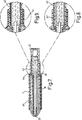
同じく図1に見られるように、ペン先14,25及びそれらの芯部分の対向しあう表面は、一方が他方から隔てられている。この特徴は、図2及び図3によく示されている。図示されているように、ペン先14,25同士の間には接触点がなく、したがって、各ペン先の流体同士のいかなる汚染をも避けることができる。図2及び図3に示されているように、ペン先25の先端は、その端部部分にまでわたって内方側へ向けて先細りとなっており、ペン先の先端同士の間の間隔が大きくなるようになっている。また、環状ペン先14の縁28は、使用されているペン先から散布される流体のいかなる交雑汚染をも避けることができる強度を有するように丸められている。一般に、ペン先25の先端の直径は約1mmとされ、環状ペン先14の内部通路の直径は2mmとされている。図3には、ペン先25の先端に設けられた穴29と、中空のチューブ30と、このチューブ内に存在する芯31とが示されている。
As can also be seen in FIG. 1, the opposing surfaces of the
図3に示されているように、使用されていないときには、環状ペン先14の先端が、内部ペン先25の先端を越えて突出している。これにより、ユーザーが、相対的に小さい圧力で使用したときには環状ペン先14のみから流体を散布することができ、そして、わずかに圧力を増大させたときには両方のペン先14、25から同時に流体を散布することができる。ペン先14とケーシング1との相対的な移動(つまり、ペン先14とペン先25との相対的な移動)は、上述の通りである。
As shown in FIG. 3, the tip of the
図4には、内部ペン先25の先端が環状ペン先14の先端を越えて突出している他の実施例が示されている。したがって、この実施例では、ユーザーが、内部ペン先のみで書くか、あるいは、わずかに圧力を増大させることによって内部ペン先及び環状ペン先の両方によって書くかを選ぶことができる。図4では、ペン先14,25同士の間の間隔が、実質的に不透過性の鞘32によって形成されている。
FIG. 4 shows another embodiment in which the tip of the
図5に示されたマーカーペンの環状ペン先14は、その先端から離れた端部に設けられた凹部33を有している。これに隣接する内部トランゾーブの端部は、この凹部内へ突出させられており、それによって環状ペン先の移動範囲が制限されている。この実施例では、内部ペン先25が、相対的に固いプラスチックの鞘35に包まれた流体保持繊維状素材34の集合体を備えている。使用されているときに、流体がペン先から例えば紙シートへと通過することを可能にするため、ペン先25の先端には穴36が設けられている。ペン先の先端から離れたプラスチックの鞘35の端部には、流体が内部トランゾーブから毛管作用によって繊維状集合体を通してペン先の先端へと通過することを可能にするために、1つあるいはそれ以上の開口部37が設けられている。
The
ペン先14の先端の端部には、このペン先14内に設けられた棚39に対してぴったりと嵌合する環状の段差38が設けられている。段差38と棚39との協働は、環状ペン先14内での内部ペン先25の移動範囲を制限する。
At the end of the tip of the
図6に示されたマーカーペンは、図1に示されたものと類似している。しかしながら、この実施例では、ケーシング1がフェルールと一体化されるように構成されており、かつ、環状トランゾーブ8の中央通路内にトランゾーブ21が略同軸状に配置されることにより、トランゾーブ8,21は一体的なものとされている。この実施例では、2つのトランゾーブが、単に不透過性プラスチックの鞘によって隔てられている。2つのトランゾーブは真空成形されていてもよい。また、環状ペン先14は略直線状をなしている。
The marker pen shown in FIG. 6 is similar to that shown in FIG. However, in this embodiment, the casing 1 is configured so as to be integrated with the ferrule, and the
図6に示されるように、先端から離れたペン先14の端部は、トランゾーブ8の一方の端部に設けられた開口部内へ突出している。他の構成として、ペン先の端部が、トランゾーブ8の繊維状集合体内へ大きいあるいは小さい範囲で突出するような、環状延長部あるいは突出小片の列を含んでいてもよい。
As shown in FIG. 6, the end of the
図7に注目すると、この実施例では、アウターケーシング1の直径が一方の端部において減少し、これによってハウジング18の一方の端部に設けられた補完ソケット42に受け止められて保持されるソケット41を形成している。ケーシングの直径の変化によって形成される環状の肩部40は、トランゾーブ8のための端部ストッパを形成している。したがって、この実施例では、トランゾーブ21が、環状ペン先14のトランゾーブ8の軸方向に変位させられている。環状ペン先14の芯の端部には、トランゾーブ8からペン先14の先端への流体の流れを補助するように、後方側へ向けて延びる複数のニップル43が設けられている。マーカーペンのペン先の端部は、空気キャップによって着脱可能に覆われていてもよい。
When paying attention to FIG. 7, in this embodiment, the diameter of the outer casing 1 is reduced at one end portion, and thereby the socket 41 is received and held by the
ハウジング18は、ソケット42から離れたハウジングの端部が環状トランゾーブ8の内部通路を通過できるようにテーパネック44を有している。ソケット42は、図8に示されるようにソケット41内への摩擦嵌合が可能な寸法とされていてもよいし、図9に示されるようにスクリューネジとの協働を介してソケット41に接続されるようにしてもよい。これに代えて、ソケット41,42が、スナップ作用を介して接続されるようにしてもよい。両方の場合、アウターケーシング15とハウジング18との間の長さ方向の相対的な移動が可能になる。このように、ペン先25の先端の位置は、ソケット41に対するソケット42の移動によって単純に変化させられる。
The
図7に見られるように、内部ペン先25は、ペン先の先端に近接した位置において、中央に位置するフェルールによってハウジング18の内壁から離間させられている。このフェルールは、圧力均等化を目的として、空気の流れを生じさせる開口部あるいはフィンを有している。
As seen in FIG. 7, the
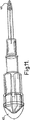
図7〜図9に示される実施例の1つの利点は、内部ペン先25を含むハウジング18を、すぐにケーシング1から引き抜き、逆にして再びケーシング1のソケット41内へ挿入することができることである。この逆の状態が、図10及び図11に示されている。このようにして、2つのペン先が分離されたり一緒にされたりして用いられる。図10及び図11に示されているように、エンドキャップ45,46が、使用されていないときのペン先の先端をシールするように設けられている。さらなる利点としては、さまざまなハウジング及びトランゾーブを、ケーシング1及びそのトランゾーブの組み合わせに応じて用いることができることである。
One advantage of the embodiment shown in FIGS. 7 to 9 is that the
図12に示される実施例では、ケーシング1が図6に示されたものと類似している。しかしながら、この実施例では、トランゾーブ8,21が、同軸状というよりはむしろ直線状に配置されている。図12に示されているように、ペン先25の芯部分が、環状トランゾーブ8の中央通路を通過するようにして長さ方向に延在しているとともに、トランゾーブ21内に存在する繊維状集合体内へ突出している。ペン先14の芯部分は、トランゾーブの内部のプラスチックの鞘によって、トランゾーブ8の流体保持繊維状集合体から保護されている。O字形状のプラスチックの鍔47が、この鍔の一方の表面とこれに対向するトランゾーブ8の端部との間に隙間を形成するように、2つのトランゾーブの対向する端部同士の間に配置されている。
In the embodiment shown in FIG. 12, the casing 1 is similar to that shown in FIG. However, in this embodiment, the
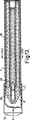
図13,図13A,図13Bに示されたマーカーペンは、2つのペン先14,25の芯の長さが実質的に減少させられている点を除いて、前述したものと類似している。内部ペン先25は、繊維状集合体で満たされた胴部48を有する挿入可能なカートリッジ47と、トランゾーブ8内に存在する繊維状集合体内へ突出する芯部分49と、ペン先の先端とを備えている。前述したように、流体は、毛管作用によってトランゾーブ8から芯部分49及び胴部48内に存在する繊維状集合体を通してペン先の先端へと通過する。図13Aには、マーカーの端部におけるペン先14,25の相対的な配置が示されている。マーカーペンのペン先の端部は、着脱可能なエンドキャップ50によってシールされている。図13Bには、トランゾーブ8,21、ケーシング1及びハウジング18の相対的な寸法及び配置が示されている。
The marker pen shown in FIGS. 13, 13A, and 13B is similar to that described above, except that the length of the nibs of the two
図14に示されるマーカーペンは、トランゾーブ8,21が同軸状あるいは直線状というよりはむしろ並行して配置されている点で、前述した実施例と異なっている。図14の実施例では、ケーシング1が、完全に隔てられた横断面円形の2つの区画51,52を備えている。もちろん、他の横断面形状が用いられてもよい。各区画は、前述したようにしてトランゾーブを受け止めている。しかしながら、この実施例では、各トランゾーブが、環状というよりはむしろ中実の円柱状の繊維状集合体を備えている。外部ペン先14は、略部分円錐形状とされているとともに、内部ペン先25を通して突出させることができるようにくりぬかれている。外部ペン先14は、ケーシング1の開口端部を横切るように延在するとともにトランゾーブ8の開口端部上に接触するように配置された台座部分53を備えている。このようにして、トランゾーブ8の繊維状集合体に保持された流体が、毛管作用によって台座部分53を介してペン先へ流れ、そこからペン先の先端へと流れることができる。一般に、環状ペン先14及び台座は、POREX素材から構成されている。その成形は一般には金型によるものである。
The marker pen shown in FIG. 14 differs from the above-described embodiment in that the
先端から離れたペン先25の端部は、トランゾーブ21内に存在する流体保持繊維状集合体内へ突出している。これにより、流体が、毛管作用によって繊維状集合体からペン先へ、そこから先端へと流れることができる。ペン先及び台座53における露出した表面は、着脱可能なエンドキャップによって覆われることが好ましい。台座53とペン先8の略部分円錐の側面とが、永久にあるいは開放可能にキャップ54によって覆われている。ケーシング1の外表面の周囲には、キャップの縁が接触させられるようにリップ55が設けられている。
The end of the
図14に示したものと類似する図示しない実施例では、ケーシング1が、チャンバー51の他方の側面側に配置されたチャンバー52に類似するもう1つのチャンバーを備えている。これにより、ケーシングは並行する3つの区画を備え、外方側の2つの区画の両方が台座53の横にそれぞれ接続されたトランゾーブ8を備えている。そのようなケーシングの断面図が図14Aに示され、端面図が図14Bに示されている。
In an embodiment (not shown) similar to that shown in FIG. 14, the casing 1 comprises another chamber similar to the
図15に示された実施例では、内部ペン先25の先端が、ペン先25のテーパ環状端部壁によって同一位置に保持されるボールベアリング56を備えている。ボールベアリングにおける露出しない表面がペン先の内部芯57に接触することにより、この表面に、芯の内部に存在する流体が常時補充される。従来の方法では、表面上にペン先で描いたときに、ボールベアリングが回転することによって、流体を筆記面に移動させることができる。ボールベアリングは、例えばステンレススチールのような金属、セラミック素材、プラスチック素材、あるいはPOREXのような多孔性素材から構成されていてもよい。
In the embodiment shown in FIG. 15, the tip of the
図16に示されるマーカーペンのペン先の先端は、ペン先25の内部表面に形成された対向した軸保持用凹部間で回転するように取り付けられたローラー58を備えている。このローラースピンドルは、符号59で示されている。ローラーの露出しない表面は、ペン先の内部芯57に接触している。このローラーには、一対の環状屹立リブが設けられており、それによって、例えば紙シートの表面上をローラーが移動することで同時に2つの線を描くことができる。
The tip of the pen tip of the marker pen shown in FIG. 16 includes a
図示されているように、ローラーの2つのリブ61における露出しない表面は、同一の芯に接触している。他の構成として、各リブが、他のリブが接触する芯から完全に隔てられた芯に接触するようにしてもよい。このようにして、異なる流体が2つのリブによって塗布されてもよい。 As shown, the unexposed surfaces of the two ribs 61 of the roller are in contact with the same core. In another configuration, each rib may contact a core that is completely separated from the core with which the other rib contacts. In this way, different fluids may be applied by the two ribs.
図17及び図18の概略図は、2つの異なるペン先の輪郭を示している。図17では、両方のペン先が断面で略矩形とされており、図18では、両方のペン先が断面で略長円形とされている。これらのペン先の1つの利点は、紙に対するペンの方向を変えるだけで、単純に描かれる線の幅を代えることができることである。 The schematic diagrams of FIGS. 17 and 18 show the contours of two different nibs. In FIG. 17, both pen nibs are substantially rectangular in cross section, and in FIG. 18, both nibs are substantially oval in cross section. One advantage of these nibs is that simply changing the orientation of the pen relative to the paper can change the width of the drawn line.
上述したように、トランゾーブ8内に存在する流体は、有色染料、散乱色素あるいは他の有色媒体を含む水性インクのような指示薬を備えていてもよいし、水を備えていてもよい。トランゾーブ21内に存在する流体は、トランゾーブ8内に存在するものとは異なる色の染料、分散色素あるいは他の有色媒体、インク内の有色染料あるいは分散色素と化学的に反応する消去素材の溶剤、あるいは、第1のペン先によって散布される有色媒体の色を消去したり変化させたりする他の有色媒体を含む水性インクのような指示薬を備えていてもよい。
As described above, the fluid present in the
本発明によるマーカーペンは、1つの色を有する相対的に幅広の縞とともに、この縞の境界に、他の色あるいは無色の1つあるいは複数の線を描くために用いられる。この効果は、紙シートのような筆記面上のペンの方向とは関係なく得ることができる。 The marker pen according to the present invention is used to draw one or more lines of another color or colorless at the border of the stripe, with a relatively wide stripe having one color. This effect can be obtained regardless of the direction of the pen on the writing surface such as a paper sheet.
縞は、環状あるいはリング形状のペン先14によって描かれ、内部の線は、ペン先25によって描かれる。図16のローラーは、2つの略平行な線を描くのに用いられる。他の色の縞の余白によって縁取られた1つの色の1つの線を描くためには、流体がペン先14へと移動させられるトランゾーブ8は、第1の色の染料を有する指示薬インクで満たされ、流体がペン先25へと移動させられるトランゾーブ21は、指示薬インクの染料と化学的に反応してそのpHを変化させる、つまり、指示薬インクの染料の色を変化させる消去媒体の溶剤で満たされる。使用されるときには、マーカーペンのペン先の端部の筆記面上の移動により、ペン先25によって散布される消去溶剤が、環状ペン先14によって既に散布された有色インクと化学的に反応して、縞の色と異なる色の線を生じさせることができる。無色の中央の線を有する縞を描くためには、指示薬インクの波長の値を可視域の外へ変化させるような消去溶剤が選択される。
The stripes are drawn by an annular or ring-shaped
この効果はまた、異なる色の2つの水性インクの色の混合をもたらす。例えば、トランゾーブ8が、第1の色(例えば黄色)の水性インクで満たされ、トランゾーブ21が、第2の色(例えば緑色)の水性インクで満たされているとする。使用されたときには、マーカーペンのペン先の端部の筆記面上の移動により、ペン先25によって散布される有色染料が、ペン先14によって散布される有色染料と混合し、例えば与えられた例では、中央のグリーンの線とともに黄色の縞を生じさせる。
This effect also results in the mixing of two aqueous ink colors of different colors. For example, it is assumed that the
水で洗浄された色の効果を出すためには、1つのトランゾーブが有色染料を含んだ指示薬インクで満たされ、他のトランゾーブが単に水で満たされるようにすればよい。 In order to produce the effect of a color washed with water, one transorb may be filled with indicator ink containing a colored dye and the other transorb simply filled with water.
ペン先14,25からの流体が同時に散布されるため、線及び縞の縁において混合が生じ、それぞれのぼやけた縁に、深み及び輪郭の幻覚効果が与えられる。この効果は、三次元的効果と言うことができる。すなわち、外観が管状となった有色の縞が得られる。従来では、これは、偉大な技術と芸術的な訓練とによってのみ達成することが可能であった。このような効果をもたらすことができるマーカーペンは知られていない。
As fluids from the
図示されない実施例において、ペン先14,25には外部源から流体が供給されるようにして、トランゾーブ8,21の必要性をなくすようにしてもよい。例えば、要求される流体に浸されたパッドによって、この流体が環状ペン先14へと移動するようにしてもよいし、同様に、ペン先25に、スポイトあるいは類似の装置によって流体が供給されるようにしてもよい。ペン先への外部補充のための他の手段が用いられてもよい。もし、流体を含む複数の区画がマーカーペンのケーシングに設けられている場合、これらは、芯によってそれぞれのペンに直接接続されている必要はない。例えば、ペン先のための流体源が、単にそれぞれの流体ごとに隔てられた容器を備えているようにしてもよい。この場合、流体が、便利に液体吸収芯を通してペン先へと接続されるようにしてもよい。例えば、ペンのケーシングの側壁が柔軟性を有するようにして、手の圧力や他の手段によって、流体が伝達されるようにしてもよい。
In an embodiment not shown, the
前述したものは、単に、本発明によるマーカーペンの一例を示したものであり、種々の変更を、本発明の思想から外れることなしに加えることができる。 What has been described above is merely an example of the marker pen according to the present invention, and various modifications can be made without departing from the spirit of the present invention.
1 ケーシング
8 トランゾーブ
14 ペン先
21 トランゾーブ
25 ペン先
1
Claims (7)
前記ハウジングの一方の端部から突出する第1の流体保持ペン先と、
前記第1のペン先の環状部内にあって前記ハウジングの前記一方の端部から前記第1のペン先と同時に突出する第2の流体保持ペン先と、
前記第1のペン先及び前記第2のペン先の表面同士、及び、前記両ペン先の前記ハウジングから離れた側の端部同士を互いに離間させる手段と、を備え、
前記第1のペン先が縞を描くような配置及び寸法とされ、
前記第2のペン先が前記縞の境界同士の間に1つの線又は複数の線を描くような配置及び寸法とされ、
前記縞及び前記1つの線又は複数の線が単一のストロークで描かれ、
前記第1のペン先が、一方の端部から他方まで通過する中央孔を有する略部分円錐とされていることを特徴とするマーカーペン。A tubular housing;
A first fluid holding nib protruding from one end of the housing;
A second fluid retaining nib that is within the annular portion of the first nib and projects simultaneously with the first nib from the one end of the housing;
Means for separating the surfaces of the first nib and the second nib, and the ends of the two nibs away from the housing, from each other;
The first nib is arranged and dimensioned to draw a stripe,
The second pen nib is arranged and dimensioned to draw one line or a plurality of lines between the stripe boundaries,
The stripe and the line or lines are drawn in a single stroke ;
The first nib, marker pen, characterized in that you have been a schematic partial cone with a central hole passing from one end to the other.
前記第1のペン先の環状部内にあって前記ハウジングの前記一方の端部からも突出させ、かつ前記ハウジング内に配置された第2のチャンバー内に存在する流体が補充される第2の流体保持ペン先と、を備え、
前記突出するペン先の先端が互いに離間され、
前記第1のペン先が縞を描くような配置及び寸法とされ、
前記第2のペン先が前記縞の境界同士の間に1つの線又は複数の線を描くような配置及び寸法とされ、
前記縞及び前記1つの線又は複数の線が単一のストロークで描かれ、
前記第2のチャンバー内に存在する前記流体が、有色染料、分散色素あるいは他の有色媒体、あるいは、使用されたときにインク内の有色染料あるいは分散色素と化学的に反応する消去素材の溶剤、あるいは、前記第1のペン先によって散布された有色媒体の色を消去したり変化させたりする他の有色媒体、を有する水性インクを含んだ指示薬を備えていることを特徴とするマーカーペン。A tubular housing with a first fluid retaining nib that is replenished with fluid present in a first chamber disposed within the housing projecting from one end;
A second fluid that is located in the annular portion of the first nib, protrudes from the one end of the housing, and is replenished with a fluid existing in a second chamber disposed in the housing. A holding nib, and
The tips of the protruding pen nibs are spaced apart from each other;
The first nib is arranged and dimensioned to draw a stripe,
The second nib is arranged and dimensioned to draw one line or a plurality of lines between the stripe borders;
The stripe and the line or lines are drawn in a single stroke ;
The fluid present in the second chamber is a colored dye, disperse dye or other colored medium, or a solvent of an erasing material that chemically reacts with the colored dye or disperse dye in the ink when used; Alternatively, a marker pen, characterized in that you are provided with indicators including an aqueous ink having the other colored media or changing or erasing the color of the sparged colored medium by the first pen tip.
少なくとも1つのペン先が、多孔性素材から構成されていることを特徴とするマーカーペン。The marker pen according to claim 1 or 2,
A marker pen, wherein at least one nib is made of a porous material.
前記第1のペン先が、吸収性素材からなる分離した複数の部分から成る略環状の配列を備えていることを特徴とするマーカーペン。In marker pen according to any one of claims 1 to 請 Motomeko 3,
The marker pen according to claim 1, wherein the first pen tip has a substantially annular arrangement composed of a plurality of separated parts made of an absorbent material.
前記第1のペン先の末端部の外表面は固く、このため該末端部は曲がらないことを特徴とするマーカーペン。In marker pen according to any one of claims 1 to 請 Motomeko 4,
The external surface surface of the first nib end piece rather solid, marker pen, characterized in that this end said distal end portion is not bent.
前記第2のペン先の末端部が、略先細りとされていることを特徴とするマーカーペン。In marker pen according to any one of claims 1 to 請 Motomeko 5,
The marker pen, wherein the end portion of the second pen tip is substantially tapered.
前記第2のペン先が、横断面で、円形とされていることを特徴とするマーカーペン。In marker pen according to any one of claims 1 to 請 Motomeko 6,
The marker pen, wherein the second pen tip is circular in cross section.
Applications Claiming Priority (2)
| Application Number | Priority Date | Filing Date | Title |
|---|---|---|---|
| GBGB0103238.2A GB0103238D0 (en) | 2001-02-09 | 2001-02-09 | Marker pens |
| PCT/GB2002/000486 WO2002064379A1 (en) | 2001-02-09 | 2002-02-06 | Marker pens |
Publications (3)
| Publication Number | Publication Date |
|---|---|
| JP2004520205A JP2004520205A (en) | 2004-07-08 |
| JP2004520205A5 JP2004520205A5 (en) | 2005-12-22 |
| JP4053426B2 true JP4053426B2 (en) | 2008-02-27 |
Family
ID=9908429
Family Applications (1)
| Application Number | Title | Priority Date | Filing Date |
|---|---|---|---|
| JP2002564138A Expired - Fee Related JP4053426B2 (en) | 2001-02-09 | 2002-02-06 | Marker pen |
Country Status (11)
| Country | Link |
|---|---|
| US (1) | US7237970B2 (en) |
| EP (1) | EP1358075B1 (en) |
| JP (1) | JP4053426B2 (en) |
| CN (1) | CN1265975C (en) |
| AR (1) | AR032902A1 (en) |
| AT (1) | ATE555917T1 (en) |
| CA (1) | CA2437806C (en) |
| GB (2) | GB0103238D0 (en) |
| MY (1) | MY127554A (en) |
| TW (1) | TW568841B (en) |
| WO (1) | WO2002064379A1 (en) |
Cited By (1)
| Publication number | Priority date | Publication date | Assignee | Title |
|---|---|---|---|---|
| KR101776292B1 (en) * | 2016-02-24 | 2017-09-07 | 한남대학교 산학협력단 | Science experiment kit of art play using capillary and acid-base reaction |
Families Citing this family (21)
| Publication number | Priority date | Publication date | Assignee | Title |
|---|---|---|---|---|
| US7188940B2 (en) * | 2003-01-31 | 2007-03-13 | Hewlett-Packard Development Company, Lp. | Vent plug methods and apparatus |
| WO2004078488A2 (en) * | 2003-03-05 | 2004-09-16 | Terence William Bolton | Colouring apparatus with marker pen |
| US7682354B2 (en) * | 2003-04-01 | 2010-03-23 | Aircom Manufacturing, Inc. | Dispenser having piezoelectric elements and method of operation |
| US20060116640A1 (en) * | 2003-04-01 | 2006-06-01 | Trompen Mick A | Dispenser having piezoelectric elements and method of operation |
| DE10315550A1 (en) * | 2003-04-05 | 2004-10-14 | Wella Ag | Applicator for applying an oxidative hair color |
| CA2536101A1 (en) * | 2003-08-18 | 2005-03-03 | Sanford, L.P. | Multiple width marking instrument |
| US7481593B2 (en) * | 2003-08-19 | 2009-01-27 | Sanford, L.P. | Combination hydrophobic/hydrophilic filters/reservoirs for controlling fluid flow |
| US7001091B1 (en) * | 2003-10-31 | 2006-02-21 | Knight Andrew F | Ink pen for dispensing ink having time-dependent characteristics |
| US8104983B2 (en) | 2003-11-11 | 2012-01-31 | Societe Bic | Combination writing instrument |
| US7954457B2 (en) * | 2005-09-14 | 2011-06-07 | Aircom Manufacturing, Inc. | Dispenser |
| JP4853850B2 (en) * | 2005-09-21 | 2012-01-11 | 公立大学法人大阪府立大学 | Writing pen device for embedding information and embedded information reading system |
| US8579529B2 (en) * | 2007-02-08 | 2013-11-12 | Avon Products, Inc | Multi-unit cosmetic applicator |
| GB0716842D0 (en) * | 2007-08-30 | 2007-10-10 | Laja Materials Ltd | Artist tool |
| US20090257811A1 (en) * | 2008-04-10 | 2009-10-15 | Chance Productions, Inc. | Multiple nib writing instrument |
| US20100054846A1 (en) * | 2008-08-29 | 2010-03-04 | Brian Hartman | Writing Instrument |
| CA2795025A1 (en) * | 2010-03-31 | 2011-10-06 | Beauty Union Global Ltd. | Refill system and method |
| CN102795023A (en) * | 2012-08-01 | 2012-11-28 | 济南蓝贝思特科技有限公司 | Environment-friendly writing pen |
| CN106470847A (en) * | 2014-07-03 | 2017-03-01 | 三菱铅笔株式会社 | Writing appliance |
| CN105891216B (en) * | 2016-04-12 | 2018-10-02 | 京东方科技集团股份有限公司 | Microscope labelling apparatus |
| KR102068874B1 (en) * | 2017-07-27 | 2020-01-21 | 남명석 | Three-color macapen |
| FR3071192B1 (en) * | 2017-09-19 | 2019-10-18 | Societe Bic | WRITING INSTRUMENT COMPRISING TWO CONCENTRIC WRITE POINTS |
Family Cites Families (16)
| Publication number | Priority date | Publication date | Assignee | Title |
|---|---|---|---|---|
| US3887287A (en) * | 1974-02-28 | 1975-06-03 | Jr Dale M Rosh | Multi-color marking implement |
| US4227930A (en) | 1978-11-13 | 1980-10-14 | Burroughs Corporation | Ball point pen, ink, and its eradicator system |
| US4557618A (en) | 1981-12-25 | 1985-12-10 | Pentel Kabushiki Kaisha | Ink and eraser of the ink |
| US5427278A (en) | 1988-09-09 | 1995-06-27 | Gardner, Iii; William G. | Highlighting-ink remover applicator |
| DE3914465A1 (en) * | 1989-05-02 | 1990-11-08 | Merz & Krell | WRITING DEVICE |
| DE3918373A1 (en) * | 1989-06-06 | 1990-12-13 | Anneliese M Krug | Two-colour writing device - incorporates absorbent rods side-by-side connected to separate ink containers |
| WO1991000810A1 (en) * | 1989-07-13 | 1991-01-24 | Dennison Manufacturing Company | Dual tip marking and writing instrument |
| US5368405A (en) * | 1989-10-30 | 1994-11-29 | Sixiong; Xie | Non-mingling multicolor marker and its process |
| US5412021A (en) * | 1992-08-24 | 1995-05-02 | Sakura Color Products Corporation | Water-base erasable ink composition for use in marking pens |
| WO1994009997A1 (en) * | 1992-10-28 | 1994-05-11 | Guillermain Jean Claude Louis | Writing instrument with simultaneous multicolour highlighting |
| US5306092A (en) * | 1993-05-05 | 1994-04-26 | Jenq Li Chen | Marking pen with gradual-layer color effect |
| US5388924A (en) * | 1994-02-07 | 1995-02-14 | Chao; Chung L. | Drawing pen having multiple side-matched absorptive drawing tips |
| US5971643A (en) * | 1998-06-22 | 1999-10-26 | Ahmed; Cindy G. | Multiple cartridge rainbow pen |
| US6554517B2 (en) * | 2001-07-19 | 2003-04-29 | Cynthia G. Ahmed | Multicolor marker |
| US6766817B2 (en) * | 2001-07-25 | 2004-07-27 | Tubarc Technologies, Llc | Fluid conduction utilizing a reversible unsaturated siphon with tubarc porosity action |
| DE20117529U1 (en) * | 2001-10-26 | 2001-12-20 | Young Jean | Multipurpose pen |
-
2001
- 2001-02-09 GB GBGB0103238.2A patent/GB0103238D0/en not_active Ceased
-
2002
- 2002-02-06 AT AT02711007T patent/ATE555917T1/en active
- 2002-02-06 US US10/467,416 patent/US7237970B2/en not_active Expired - Lifetime
- 2002-02-06 EP EP02711007A patent/EP1358075B1/en not_active Expired - Lifetime
- 2002-02-06 CA CA002437806A patent/CA2437806C/en not_active Expired - Fee Related
- 2002-02-06 CN CN02806595.6A patent/CN1265975C/en not_active Expired - Fee Related
- 2002-02-06 WO PCT/GB2002/000486 patent/WO2002064379A1/en active Application Filing
- 2002-02-06 GB GB0202736A patent/GB2374046B/en not_active Expired - Fee Related
- 2002-02-06 JP JP2002564138A patent/JP4053426B2/en not_active Expired - Fee Related
- 2002-02-07 TW TW091102244A patent/TW568841B/en not_active IP Right Cessation
- 2002-02-08 AR ARP020100426A patent/AR032902A1/en not_active Application Discontinuation
- 2002-02-08 MY MYPI20020456A patent/MY127554A/en unknown
Cited By (1)
| Publication number | Priority date | Publication date | Assignee | Title |
|---|---|---|---|---|
| KR101776292B1 (en) * | 2016-02-24 | 2017-09-07 | 한남대학교 산학협력단 | Science experiment kit of art play using capillary and acid-base reaction |
Also Published As
| Publication number | Publication date |
|---|---|
| CA2437806A1 (en) | 2002-08-22 |
| CN1265975C (en) | 2006-07-26 |
| CN1501865A (en) | 2004-06-02 |
| US7237970B2 (en) | 2007-07-03 |
| EP1358075A1 (en) | 2003-11-05 |
| CA2437806C (en) | 2009-08-25 |
| TW568841B (en) | 2004-01-01 |
| US20040161282A1 (en) | 2004-08-19 |
| AR032902A1 (en) | 2003-12-03 |
| MY127554A (en) | 2006-12-29 |
| GB2374046A (en) | 2002-10-09 |
| EP1358075B1 (en) | 2012-05-02 |
| JP2004520205A (en) | 2004-07-08 |
| GB2374046B (en) | 2004-09-01 |
| GB0103238D0 (en) | 2001-03-28 |
| GB0202736D0 (en) | 2002-03-27 |
| ATE555917T1 (en) | 2012-05-15 |
| WO2002064379A1 (en) | 2002-08-22 |
Similar Documents
| Publication | Publication Date | Title |
|---|---|---|
| JP4053426B2 (en) | Marker pen | |
| JP2004520205A5 (en) | ||
| JP2019526470A (en) | Retractable fluid coating device | |
| JP2018122566A (en) | Writing instrument | |
| CA2566448C (en) | Colouring apparatus | |
| JP7258954B2 (en) | writing instrument | |
| CN100589990C (en) | Colouring apparatus used in marking pen and butt joint component of hte colouring apparatus | |
| JP2020073349A (en) | Writing instrument | |
| JP7158203B2 (en) | Applicator | |
| KR100653488B1 (en) | Marker pens | |
| JP7224136B2 (en) | writing instrument | |
| JP4929163B2 (en) | Coloring equipment | |
| JP7145747B2 (en) | compound writing instrument | |
| JP7224137B2 (en) | writing instrument | |
| KR20060053046A (en) | Marker pens | |
| TWM247409U (en) | Marker pens | |
| WO2004078488A2 (en) | Colouring apparatus with marker pen | |
| JP2022020265A (en) | Writing instrument | |
| TWM266175U (en) | Colouring apparatus | |
| GB2442158A (en) | Changing the colour of a marker pen using a docking station | |
| TH32553B (en) | Marker pen | |
| MX2007008030A (en) | Colouring apparatus | |
| JP2000033797A (en) | Applicator tool |
Legal Events
| Date | Code | Title | Description |
|---|---|---|---|
| A521 | Request for written amendment filed |
Free format text: JAPANESE INTERMEDIATE CODE: A523 Effective date: 20041227 |
|
| A621 | Written request for application examination |
Free format text: JAPANESE INTERMEDIATE CODE: A621 Effective date: 20041227 |
|
| A131 | Notification of reasons for refusal |
Free format text: JAPANESE INTERMEDIATE CODE: A131 Effective date: 20060411 |
|
| A601 | Written request for extension of time |
Free format text: JAPANESE INTERMEDIATE CODE: A601 Effective date: 20060711 |
|
| A602 | Written permission of extension of time |
Free format text: JAPANESE INTERMEDIATE CODE: A602 Effective date: 20060719 |
|
| A521 | Request for written amendment filed |
Free format text: JAPANESE INTERMEDIATE CODE: A523 Effective date: 20061011 |
|
| A131 | Notification of reasons for refusal |
Free format text: JAPANESE INTERMEDIATE CODE: A131 Effective date: 20061212 |
|
| A601 | Written request for extension of time |
Free format text: JAPANESE INTERMEDIATE CODE: A601 Effective date: 20070312 |
|
| A602 | Written permission of extension of time |
Free format text: JAPANESE INTERMEDIATE CODE: A602 Effective date: 20070319 |
|
| A521 | Request for written amendment filed |
Free format text: JAPANESE INTERMEDIATE CODE: A523 Effective date: 20070612 |
|
| TRDD | Decision of grant or rejection written | ||
| A01 | Written decision to grant a patent or to grant a registration (utility model) |
Free format text: JAPANESE INTERMEDIATE CODE: A01 Effective date: 20071106 |
|
| A61 | First payment of annual fees (during grant procedure) |
Free format text: JAPANESE INTERMEDIATE CODE: A61 Effective date: 20071205 |
|
| FPAY | Renewal fee payment (event date is renewal date of database) |
Free format text: PAYMENT UNTIL: 20101214 Year of fee payment: 3 |
|
| R150 | Certificate of patent or registration of utility model |
Free format text: JAPANESE INTERMEDIATE CODE: R150 |
|
| FPAY | Renewal fee payment (event date is renewal date of database) |
Free format text: PAYMENT UNTIL: 20111214 Year of fee payment: 4 |
|
| FPAY | Renewal fee payment (event date is renewal date of database) |
Free format text: PAYMENT UNTIL: 20121214 Year of fee payment: 5 |
|
| FPAY | Renewal fee payment (event date is renewal date of database) |
Free format text: PAYMENT UNTIL: 20121214 Year of fee payment: 5 |
|
| FPAY | Renewal fee payment (event date is renewal date of database) |
Free format text: PAYMENT UNTIL: 20131214 Year of fee payment: 6 |
|
| R250 | Receipt of annual fees |
Free format text: JAPANESE INTERMEDIATE CODE: R250 |
|
| LAPS | Cancellation because of no payment of annual fees |