JP4051092B2 - Free-rotating pre-leveling torque nut - Google Patents
Free-rotating pre-leveling torque nut Download PDFInfo
- Publication number
- JP4051092B2 JP4051092B2 JP54386198A JP54386198A JP4051092B2 JP 4051092 B2 JP4051092 B2 JP 4051092B2 JP 54386198 A JP54386198 A JP 54386198A JP 54386198 A JP54386198 A JP 54386198A JP 4051092 B2 JP4051092 B2 JP 4051092B2
- Authority
- JP
- Japan
- Prior art keywords
- section
- ring
- lumen
- neck portion
- nut
- Prior art date
- Legal status (The legal status is an assumption and is not a legal conclusion. Google has not performed a legal analysis and makes no representation as to the accuracy of the status listed.)
- Expired - Fee Related
Links
- 230000036316 preload Effects 0.000 claims description 19
- 239000000565 sealant Substances 0.000 claims description 19
- 230000006835 compression Effects 0.000 claims description 14
- 238000007906 compression Methods 0.000 claims description 14
- 238000009434 installation Methods 0.000 claims description 14
- 230000003247 decreasing effect Effects 0.000 claims 1
- 239000000463 material Substances 0.000 description 9
- 230000013011 mating Effects 0.000 description 8
- 239000011295 pitch Substances 0.000 description 6
- XAGFODPZIPBFFR-UHFFFAOYSA-N aluminium Chemical compound [Al] XAGFODPZIPBFFR-UHFFFAOYSA-N 0.000 description 5
- 229910052782 aluminium Inorganic materials 0.000 description 5
- 230000004323 axial length Effects 0.000 description 4
- 238000010276 construction Methods 0.000 description 4
- 238000000034 method Methods 0.000 description 4
- 230000000712 assembly Effects 0.000 description 3
- 238000000429 assembly Methods 0.000 description 3
- RTAQQCXQSZGOHL-UHFFFAOYSA-N Titanium Chemical compound [Ti] RTAQQCXQSZGOHL-UHFFFAOYSA-N 0.000 description 2
- 238000005520 cutting process Methods 0.000 description 2
- 230000007423 decrease Effects 0.000 description 2
- NUJOXMJBOLGQSY-UHFFFAOYSA-N manganese dioxide Chemical compound O=[Mn]=O NUJOXMJBOLGQSY-UHFFFAOYSA-N 0.000 description 2
- 238000004519 manufacturing process Methods 0.000 description 2
- 230000004044 response Effects 0.000 description 2
- 238000000926 separation method Methods 0.000 description 2
- 229910052719 titanium Inorganic materials 0.000 description 2
- 239000010936 titanium Substances 0.000 description 2
- 229910001069 Ti alloy Inorganic materials 0.000 description 1
- 230000009471 action Effects 0.000 description 1
- 230000015572 biosynthetic process Effects 0.000 description 1
- 230000008859 change Effects 0.000 description 1
- 238000010273 cold forging Methods 0.000 description 1
- 239000002131 composite material Substances 0.000 description 1
- 125000004122 cyclic group Chemical group 0.000 description 1
- 238000013461 design Methods 0.000 description 1
- 238000011161 development Methods 0.000 description 1
- 230000018109 developmental process Effects 0.000 description 1
- 239000006185 dispersion Substances 0.000 description 1
- 239000012530 fluid Substances 0.000 description 1
- 230000001788 irregular Effects 0.000 description 1
- 230000007246 mechanism Effects 0.000 description 1
- 238000012986 modification Methods 0.000 description 1
- 230000004048 modification Effects 0.000 description 1
- 235000011837 pasties Nutrition 0.000 description 1
- RGCLLPNLLBQHPF-HJWRWDBZSA-N phosphamidon Chemical compound CCN(CC)C(=O)C(\Cl)=C(/C)OP(=O)(OC)OC RGCLLPNLLBQHPF-HJWRWDBZSA-N 0.000 description 1
- 230000008569 process Effects 0.000 description 1
- 238000012545 processing Methods 0.000 description 1
- 230000009467 reduction Effects 0.000 description 1
- 230000003252 repetitive effect Effects 0.000 description 1
- 238000005096 rolling process Methods 0.000 description 1
- 239000013585 weight reducing agent Substances 0.000 description 1
Images


Classifications
-
- F—MECHANICAL ENGINEERING; LIGHTING; HEATING; WEAPONS; BLASTING
- F16—ENGINEERING ELEMENTS AND UNITS; GENERAL MEASURES FOR PRODUCING AND MAINTAINING EFFECTIVE FUNCTIONING OF MACHINES OR INSTALLATIONS; THERMAL INSULATION IN GENERAL
- F16B—DEVICES FOR FASTENING OR SECURING CONSTRUCTIONAL ELEMENTS OR MACHINE PARTS TOGETHER, e.g. NAILS, BOLTS, CIRCLIPS, CLAMPS, CLIPS OR WEDGES; JOINTS OR JOINTING
- F16B31/00—Screwed connections specially modified in view of tensile load; Break-bolts
- F16B31/02—Screwed connections specially modified in view of tensile load; Break-bolts for indicating the attainment of a particular tensile load or limiting tensile load
- F16B31/021—Screwed connections specially modified in view of tensile load; Break-bolts for indicating the attainment of a particular tensile load or limiting tensile load by means of a frangible part
Abstract
Description
発明の概要背景
本発明はプリベリング・トルク機能を有するねじ留め具を含む留め具システムに関する。
ねじ留め具組立体は、航空宇宙および産業構造の多くの用途に使用されている。このような組立体はねじ付きボルトまたはスタッドと、これに合ったねじ山形状を有するナット部材とを含む。振動または反復的な荷重の変動を受ける用途では、このようなねじ留め具組立体は、その保持トルクを失って緩むことが知られている。このような動作を防止するため、ねじ留め具組立体は、緩んだり、接合されるワークピースまたは品物の締付けが失われたりすることに抵抗するプリベリング・トルク機能を提供するよう改造されてきた。プリベリング・トルク機能は、噛合うねじ山形状の一方に歪んだ部分を設けることによって達成することが多く、したがって歪んだねじ部分と歪んでいないねじ部分とが噛合うと、ナット部材とスタッドまたはボルトとが、ねじ山の締め代によるプリベリング・トルクでさらに互いに保持され、その結果、トルク解除に抵抗し、したがって振動による緩みに抵抗することになる。
標準的な歪んでいないねじ形状の場合、ナット部材は、ワークピース係合及びワークピースの初期締め付けか、又は予荷重付加まで、低トルク値でボルトまたはスタッド上に自由回転する。その後、加えたトルクの大きさに対して獲得された最終締付け荷重は、主に、荷重下の回転部材の係合部分間の固有の摩擦によって抵抗を受ける。このことは歪んだプリベリング・トルクねじ形状を有するねじ留め具には当てはまらない。歪んだねじ部分が相手のねじ山と噛合うと、ナット部材はもはや自由に回転せず、加えたトルクの大きさに対して、締め付けたワークピースの締付け荷重が減少する。ねじ形状の歪みは、往々にしてナットの外端または後端に配置されるが、このことはナット部材のスタッドまたはボルト上での自由回転機能を制限し、加えられたトルクに対する初期予荷重および最終締付け荷重の大きさを制限する。また、歪んだねじ山と歪んでいないねじ山との間の噛み合いは、グリップ範囲にわたって多少グリップに敏感である。すなわち、グリップ範囲とは1つのサイズの留め具によって互いに固定されるワークピースの全厚さの最大グリップまたは全厚さから最小グリップまたは全厚さへの変動である。
本発明は、自由に回転して、ワークピースを予め選択した第1トルク規模まで締め付けることができる独特のナット部材を提供する。第1トルク規模は、ワークピースに所望の初期予荷重規模を提供するよう選択される。この第1トルク規模が自由回転ステップで達成された後、半径方向の圧縮力が誘発され、それによってナット部材とボルトまたはスタッドとの間で噛み合ったねじ山に摩擦負荷がかかる。トルク、したがって圧縮力は、予め選択した第2トルク規模が達成されるまで増加し、達成されると設置が完了する。その結果、ワークピースが予め選択された規模の最終締付け荷重で互いに保持され、設置された留め具のナットとボルトまたはスタッドの噛み合ったねじ山が、高い圧縮荷重で互いに保持された状態で、締め付けた接合部が生じ、その結果、取外しを阻む高いプリベリング・トルクが提供され、振動または他の周期的加重による緩みを所望の通りに阻む。
本発明の好ましい形態では、ナット部材は、初期予荷重が脆弱な部分によって決定され、第1トルク規模が達成されて脆弱部分が破砕した後に圧縮荷重が発生する一体構造である。
本発明のナット部材の自由回転機能は、複合材料で作成されるワークピースを使用する用途を含め、航空宇宙用途での使用に望ましい。
本発明の独特なナット部材は、既存のボルトまたはスタッドで利用可能な概ね標準的なねじ形状を含め、種々のねじ形状で使用することができる。
本発明の独特のナット部材の自由回転機能は、関連した留め具のグリップ範囲にわたって、ほぼ均一に作動することができる。
独特なナット部材の自由回転機能、およびその結果としてのプリベリング・トルク特徴は、多くの航空宇宙および非航空宇宙用途に望ましい。
したがって、プリベリング・トルクの特徴を有する独特のねじ留め具を提供することが、本発明の目的である。
噛み合ったねじ山間の締め代又は高い摩擦荷重なしで、予め選択した規模の初期予荷重を提供し、初期予荷重を達成した後、プリベリング・トルク特徴を提供するようになっている自由回転ナットを含め、独特のねじ留め具を提供することが、本発明の別の目的である。
また、航空宇宙用途に使用され、プリベリング・トルク機能がある、またはない留め具は、最終設置後、軽量の構造で、最小のサイズであることが非常に重要である。
したがって、設置後にプリベリング・トルク機能も提供し、軽量の構造である自由回転ナットを含め、独特のねじ留め具を提供することが、本発明のさらに別の目的である。
本発明の他の目的、特徴および利点は、以下の説明および添付の請求の範囲を、添付図面と組み合わせて解釈することによって明白になる。
図面の説明
図1は、本発明の機能を実現する一形態のナット部材の側断面図である。
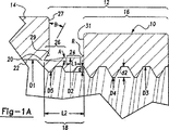
図1Aは、図1のナット部材の円で囲んだ区域1Aの部分を拡大した部分断面図である。
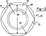
図2は、概ね矢印2−2の方向に見た図1のナット部材の端面図である。
図3は、留め具組立体でワークピースに初期荷重を与えた後、互いに固定されるよう、ボルトおよびワークピースと組立体関係にある図1および図2のナット部材を、最大グリップ状態を表すワークピースとともに、ナット部材を断面で示した側面図である。
図4は、ナット部材とボルトとの留め具組立体を、その留め具組立体の最大グリップのワークピースの最終設置状態で示す、図3と同様の側面図である。
図5は、図4と同じナット部材とボルト部材との留め具組立体を、その留め具組立体の最小グリップ状態のワークピースの最終設置状態で示す、図4と同様の側面図である。
図6は、外端部に脆弱な駆動部分を有する一体ナットの別の形態の側断面図である。
図7は、概ね矢印7−7の方向に見た図6のナット部材の端面図である。
図8は、変形した状態で、図3の矢印8−8の方向に見た、図1の一体ナット部材の変形形態の図2と同様の端面図である。
図9は、ボルトに組み付けた関係で、ナット部材の首部分に半径方向のコンプライアンスを増加させる複数の軸方向の溝を設けた図1から図4のナット部材の変形した形態を示す拡大部分断面図である。
図面の実施形態の説明
図面の図1、図1Aおよび図2を参照すると、ナット部材10が図示され、ナット部材はナット区間12およびロックリング区間14を含む。ナット区間12は、主本体部分16と、実質的に減少された断面の小さい首部分18とを含む。ナット区間12は、首部分18の外端部で脆弱なリブ20によってリング区間14の内端部と一体接続される。図1、図1Aおよび図2の実施形態では、主本体部分16は、周知の、または標準の構造のソケット工具による係合を容易にし、それによってナット部材10にトルクを与えられるよう、六角形の外表面21を有する(図2参照)。リング区間14は、概ね円形の断面を有する環状の形状で、予め選択した直径D1の滑らかな貫通内腔22がある。
図1および図1Aを見ると、首部分18は、一定外径D2の軸方向に概ね直線の区間24を有する。外径D2はロックリングの内腔22の直径D1より大きい。これは、以下で述べる目的のために予め選択された締め代を提供する。直線区間24は面取り半径Rによって主本体部分16に接続される。テーパ区域26は外部テーパ表面を有し、直線区域24を脆弱リブ20に接続する。
ナット区間12は、主本体部分16を通って延在する貫通ねじ内腔28と、首部分18とを有する。内腔28のねじ山の谷径D3は、リング区間14の内腔22の直径D1より小さい。したがって、相手の雄ねじ部材はクリアランスがある状態でリング内腔22を通過することができる。内腔28のねじ山の頂は、主本体部分16の内腔28の一部に直径D4を有し、以下で述べる目的のために首部分18のねじ形状の半径方向の深さd1を小さくするよう、先端を切って、より大きい直径D5になっている。
テーパ区間26の先端の外表面は、リング区間14の表面27の内面から脆弱リブ26まで、軸方向および半径方向内側に延在し、それと同時に、角度を付けた環状表面が内面27からテーパ区間26の端部分へと半径方向内側に延在し、環状で角度を付けて延在する切欠き29を規定する。以下で分かるように、切欠き29には、リング区間14の表面27の内面と、主本体部分16のこれに直面する内表面31とが噛み合っても、面取り半径Rの噛み合いが最小になるか、噛み合わないような角度を付ける。この方法で、面取り半径Rへの局所的な接触応力が回避される。それと同時に、リブ20が所望のトルク規模で破断するのを促進するよう、切欠き29の深さを選択することができる。面取り半径Rのサイズは、ナット部材10の材料の強度および弾性に応じて変更できることに留意されたい。したがって、ナット部材10がチタン合金などの高力材料で作成され、所望の弾性を有する場合、面取り半径Rのサイズを小さくすることができ、切欠き29を基本的に省略することができる。
次に図3および図4を見ると、ナット部材10が、ボルト30に組み付けた関係で、留め具組立体32を規定するよう図示され、留め具組立体32はワークピース46と48を互いに固定する過程にある。ボルト30は、一方端に拡大した皿頭36、反対側の端部にねじ部分38を備えた細長い胴34を有する。滑らかな胴部分40が、ねじ部分38をボルトの頭36と接続する。ボルト30の胴34は、それぞれワークピース46および48の整合された開口または内腔42および44を通って延在するようになっている。内腔44は、皿頭36を相手として受けるようになっている皿穴部分49を有する。胴のねじ部分38は、ナット区間12のねじ付き内腔28のねじ山と噛合うようになっているほぼ均一なねじ形状を有する。図3に示すように、ナット部材10は、適切な工具(図示せず)で六角形の主本体部分16を介して与えられたトルクにより、ねじ部分38にねじ山で固定され、予め選択された初期予荷重または締付け荷重規模で、ワークピース46と48を互いに締め付けている。この連結箇所で、ロックリング区間14はまだ脆弱リブ20によって首部分18に接続されている。
留め具組立体32の設置時に、ナット部材10は適切な工具または手によってボルト30に当てられ、最初にナット区間12をボルトの胴34のねじ部分38にねじ込むことができる。次に、追加のトルクを与え、留め具組立体32を最終的に設置するため、工具を使用することができる。ナット部材10がワークピース46の外表面51と係合した状態で、所望の規模の初期締付け荷重または予荷重は、所定の第1トルク規模を与えることによって達成される。この時点までナット部材10は基本的にボルトの胴34のねじ部分38上を自由に回転する。トルクの規模が所定の第2規模まで増加されると、脆弱リブ20が剪断され、首部分18が軸方向に移動してロックリング区間14の内腔22に入る。首部分18が軸方向に移動してリングの内腔22に入ると、テーパ区域26の前端が半径方向内側に押しやられ、ボルト胴のねじ部分38の相手となるねじ山と圧縮状態で噛合う。加えられるトルクの規模がさらに増加すると、テーパ区域26全体、次に直線区間24が内腔22に入り、相手となるボルトねじ山と圧縮状態でぴったり噛合う。直線区間24が内腔22に入った後に、最終的な所定のトルク規模が感知され、その規模の達成時に操作が中断される。本発明の好ましい形態では、直線区間24はリングの内腔22に完全に入れられ、それぞれロックリング区間14とナット区間24の対面する表面27と31を図4に示すように噛み合わせる。対面する表面27と31とが噛合うこのような構造は、所望の規模のトルクが与えられ、したがってワークピース46および48上で所望の規模の最終締付け荷重が達成されたか素早く目視検査し、検証する手段を提供する。これは、噛み合ったねじ山間のロックが完成し、最大になっていることも保証する。首部分18の螺旋ねじ山が少なくとも2つのねじ山ピッチに延在することが望ましいことも考えられる。
ナット区間12は、ボルト30より多少硬度の低い材料で作成することができる。したがって、首部分18のねじ山は、首部分18が軸方向に移動されてリング内腔22に入ると、圧縮噛み合いに応答してボルト30の胴のねじ部分38にある相手となるねじ山の形状へと、わずかに変形することができる。それと同時に、ボルト30の胴部分38の噛み合ったねじ山はほぼ歪まない状態のままである。
航空宇宙用途では、接合されるワークピースの間にシーラントを使用して、流体が通らない接合部を設けることが普通である。このような場合、脆弱リブ20の破断荷重は、ワークピース46、48を十分な予荷重で引き合わせることができ、リブ20が破断せずに、その間に配置された余分なシーラントを絞り出すのに十分な規模になるよう、選択することができる。この点で、最初に、ワークピース46、48を引き合わせて係合させ、その間の余分なシーラントを排出し、予め選択した期間だけ接合部を定着させるのに十分な規模の締付け荷重を加え、次に戻し、ナット区間12を通してナット部材10に追加のトルクを加え、最終締付け荷重を達成するのが普通の手順である。この場合、リブ20は第1ステップ中に無傷のままで、したがって破断しないよう構成することができる。第2ステップでは、所与の時間をかけて接合部が固まった後、ナット区間12に再度トルクを加える。リブ21は、第1ステップで加えた規模より大きい規模のトルク荷重で破断し、さらに増加した規模の追加トルクが加えられると、首部分18が移動してリング内腔22に完全に入り、設置が完了する。言うまでもなく、設置は上述したような2ステップではなく、シーラントの有無にかかわらず1ステップでも実行できることを理解されたい。また、リブ20は、この第1締付けステップ中に破断し、破断の発生でシーラントが絞り出され、作業者にその時点で追加トルクを加えるのを停止するよう指示または信号を提供するよう構築できることも理解されたい。このようなシーラントは、通常は、二酸化マンガンの分散クラスのシーラントであるCourtaulds AerospaceのPR1776b2などの、ペースト状の材料である。
ナット部材10とボルト30間のトルク印加を容易にするため、胴34の外端に、設置用工具(図示せず)の同様形状のロッドを受けることができる六角形または他の不規則な形状の内腔50を設けることができる。ロッドは回転により固定され、したがって工具の六角形のソケット部分のみが回転し、それによってナット部材10およびボルト30がワークピースの内腔42、44内でつれ回りするのを防止する。このようなつれ回りが生じると、内腔42、44などのワークピースの内腔に望ましくないかじりが生じることがある。このような工具の詳細は、当業者の範囲内であり、本発明の一部を構成しないので、単純化のために省略してある。
図4から分かるように、この時点で、ナット区間12のねじ内腔28のねじ山はほぼ全部がボルト30のねじ部分38のねじ山と完全に噛み合っている。
前述の通り、首部分18の前端から後方に向かって、ねじ山の少なくとも幾つかの頂は、先端が切ってある。一つの形態では、ネック部分18の頂は、主本体部分16を含めナット区間にある残りの全ねじ山の通常の半径方向深さd2に対して、約半分の半径深さd1まで小さくなっている。これには幾つかの目的がある。第1に、これは交差ねじ込みを防止しながら、ボルト30の胴のねじ部分38との初期ねじ係合を容易にする。第2に、首部分18のテーパ区域26のテーパ状になった厚さと組合された先端を切ったねじ山は、リング区間14の内腔22内への首部分18の初期軸方向移動の促進と、余分な摩擦や噛合うボルトねじ山の永久歪みを生ぜずに、半径方向の圧縮による高いプリベリング・トルクの発展の促進を助ける。深さd1が頂の通常の半径方向深さd2の約25%から約75%になるような先端切りや半径方向深さの減少は、このような有利な結果をもたらすと考えられる。本発明の一つの形態では、半径方向の深さを約50%減少させることが望ましい。頂の半径方向深さを減少させることにより、首部分18はさらによく適合し、これによって、所望の半径方向圧縮と、留め具の高いプリベリング・トルク特性の達成を容易にする。さらに、首部分18のねじ山の前端での頂の半径方向深さの減少、その結果としての適合する構造は、ワークピース46の表面51がナット部材10の軸Xに対して多少角度を有する用途で、ナット部材10の使用を容易にする。これに対して、主本体部分16を含め、ナット区間12の残りのねじ山は、通常のねじ深さd2であり、これはボルトのねじ部分38の相手となるねじ山の半径方向深さとほぼ等しい。それと同時に、リング区間14は、十分な肉厚を有するよう構築され、これによってリング区間14の半径方向の膨張が防止される。この点で、首部分18の直線区域24に、内表面31に近い後端で、全半径方向深さd2の先端を切っていない螺旋ねじの少なくとも1つのねじ山ピッチが設けられる場合もある。(図9参照。)
テーパ区域26の半径方向外表面は、脆弱リブ20との接続部で、リング区間内腔22の直径D1よりわずかに小さい外径D8で始まることが分かる。初期リードでの直径D8のわずかな減少は、増加する軸方向荷重に応答するテーパ区域26のリング内径22内への初期移動を促進し、脆弱リブ20の破断荷重が達成された後のテーパ区域26の座屈が防止される。テーパ角度Aは、一部は、テーパ区域26の前端とリング内腔22との適切な初期摩擦噛合いを提供し、脆弱リブ20の初期分離後に、跳ね返りまたは締付けの喪失を防止するのに十分なように選択される。一形態では、テーパ区域26の外表面は中心軸Xに対して約8°の角度Aで先細になり、前端の小径D8から直線区域24の大径D2へと拡張する。この点に関して、テーパ角度Aは約3°から約13°、好ましくは約6°から約10°まで変化できると考えられる。直線区間24は、首部分18の長さL2の概ね約10%から約75%延在することができる。これはある程度までは、ナット部材10の材料および全体的サイズによって決定される。
首部分18に直線区域24を設けることも有利と考えられる。この点に関して、直線区域24とリング内腔22の表面との圧縮噛合は、テーパ区域26のテーパ表面のようなテーパ表面のみがリング内腔22と噛み合った場合よりも、面と面との摩擦噛合いのより大きい、より均一な領域を提供する。それと同時に、直線区間24のねじ山の少なくとも一部は、半径方向に完全な深さにするか、テーパ区域26より先端を切る量を少なくすることができ、その結果、ねじ部分38の噛み合ったねじ山との締め代の規模が大きくなる。(図9参照)。この増加した表面係合と圧縮荷重はより大きいプリベリング・トルクとなる。さらに、しかし、プリベリング・トルクを保持する圧縮荷重は、一部は直線のほぼテーパのない表面間の係合によって維持され、これによって保持力がテーパ表面の係合のみから得られる場合に生じるような振動からの緩みを防止する。この点に関して、直線区域24とリング内腔22との軸方向に直線の非テーパ表面間の最終係合は、完成した設備のボルト30からナット部材10が振動で緩むのを阻止する力を向上させる。しかし、直線区域24の軸方向の長さL1は、設置時、全長にわたって内腔22内に移動されるように望ましい長さに維持され、それによって対面する表面27と31が互いに係合する。
リング内腔22のほぼ直線の表面と係合する直線区域24の設置は、首部分18のみにテーパを付けた場合よりも、より予測できる最終締付け荷重の規模を提供するとも考えられる。これは、部分的に、直線区域24が軸方向に動かされてリング内腔22に入ると、最終締付け荷重が、リング区間14を半径方向に拡張するために必要なボルト30とナット部材10間の相対的な軸力の規模によってもある程度決定される結果である。
ナット区間12とボルト30との間に追加のロックを提供するため、ボルト胴34のねじ部分38に軸方向のスロットまたは溝53を設けることができる。(図3および図4参照)。したがって、首部分18、特に直線区域24がリング内腔22の十分内側の最終位置に到達すると、材料の一部が変形して溝53に入り、その結果、ボルト30とナット部材10間に追加の機械的ロック作用が生じる。スロット53内のロックの有効性は、スロット53に約90°の角を付けるか、胴のねじ部分38のねじ山の螺旋角度に対して直角位相にすると向上すると思われる。このような軸方向ロックスロット53の使用は任意選択である。というのは、スロット53がなくても、高レベルのプリベリング・トルクが達成されるからである。
ロックリングの内腔22の直径D1が約.859cm(.338インチ)である図1から図4の実施例の一形態では、直線区域24の直径D2が約.876cm(.345インチ)になるよう選択された。その結果、直線区域24と内腔22との半径方向の締め代は、半径方向のサイドごとに約.0089cm(.0035インチ)となる。半径方向のサイドごとに約.0025cm(.001インチ)から約.013cm(.005インチ)の半径方向の締め代があると、噛み合ったねじ山間に所望の規模の圧縮力が得られ、所望の規模のプリベリング・トルクが達成されると考えられる。この点に関して、内腔22にわずかなテーパを形成し、冷間鍛造または冷間すえ込みによるリング区間14の製造を容易にすることができる。リング区間14には概ね均一な半径方向の肉厚が設けられるので、外表面も同様に角を付けられる。したがって、内腔22は開放端の大きい方の直径から、首部分18に近い端部でのわずかに小さい方の直径へと、直径方向にテーパを付される。上述した実施形態の直径の全体的な変化は約.015cm(.006インチ)となる。これは、直線区域24が内腔22と係合し、さらに最終的な設置状態で首部分18がその全長にわたって内腔22内に延在しないことを考えると、首部分18で容易に対応することができる。図4および図5参照。
前述したように、切欠き29には、表面27が面取り半径Rとほとんど、または全く係合しない状態で、表面27と31とが係合するよう角を付ける。前述し、7075−T73アルミで作成したナット部材10の形態では、首部分18の全長L2は約.191cm(.075インチ)であり、面取り半径Rが開始するまでの直線区域24の長さL1は約.033cm(.013インチ)であった。
首部分18と本体部分16との接合部の半径Rは、首部分18のフープ圧縮強度と面取り半径Rの応力集中係数との平衡を取るよう選択される。大きい面取り半径Rは、内腔22に入るにつれ、首部分18の半径方向の圧縮に抵抗する。この点に関して、切欠き29がこの抵抗を最小にするよう作用する。というのは、大きい面取り半径Rは内腔22に入るにつれ、面取り半径Rの少なくとも一部にクリアランスを提供するからである。面取り半径Rが小さすぎると、特にナット部材10がアルミなどの比較的低い強度の材料で作成される場合、応力集中が望ましくないほど高いレベルになることがある。また、このような小さい面取り半径Rは、その点におけるナット区間12の引張り強度を低下させる。部材10をアルミ7075−T73で作成し、直線区域24の直径D2が上述した通りで、六角形の平坦部の差し渡し直径寸法D6が約1.110cm(.437インチ)である本発明の一形態では、約.076cm(.030インチ)の半径Rで満足できることが判明している。表面27の内面に対する切欠き29の外表面の角度Bは、約20°になるよう選択された。ナット区間12の外表面の平坦部は、リング区間14の外表面の直径D7より小さい直径D6だけ、半径方向に間隔があいている。それと同時に、六角形表面21の対向する隅は、直径D2よりわずかに小さく、概ね直径方向に離隔している。この幾何学的形状は、ナット部材10の製造を容易にする。
7075−T73アルミで作成したナット部材を有し、−10直径サイズの、上述したような本発明の形態では、5/16−24UNJF−3bのねじ形を使用した。ボルト30には、胴のねじ部分38上に相手となるねじ形が設けられた。
前述したように、ナット部材10を比較的高い強度の材料で作成する場合は、半径Rのサイズを最小にし、切欠き29を基本的になくすことができる。したがって、ナット部材10がアルミの場合で述べたのと概ね同じサイズで、3A1-2.5Vチタンで作成されている場合、半径Rを約0.13cm(.005インチ)と最小にすることができる。それと同時に、切欠き29などの切欠きをなくすことができる。したがって、リブ20の破断荷重は、切欠き29などの切欠きとは無関係に設計要素から決定される。航空宇宙用途では、高力留め具組立体32を提供するため、相手となるボルト30は6A1−4Vチタン材料でよい。上述したように、特にロックスロット53をなくした構造では、相手となるねじ山に永久歪みが非常に少ない、または永久歪みがない状態で、高いプリベリング・トルク機能が提供される。したがって、望まれるならば、留め具組立体32は設置後にワークピース46および48からねじ分離され、外されることができる。このようなねじ分解は、初期分離トルクが多少高いロックスロット53を使用した場合でも、達成することができる。
留め具組立体32が、妥当なグリップ範囲にわたってワークピース46および48などのワークピースを固定するのに使用されることが望ましい。留め具組立体32などの留め具組立体のグリップ範囲は、前述したように、同じ留め具組立体で互いに固定できるワークピース46および48などのワークピースの最大、最小全厚さの差として規定される。図3および図4では、この留め具組立体32にとって最大全厚さまたは最大グリップのワークピース46および48を固定する留め具組立体32が図示されている。この点で、滑らかな胴部分40は、ボルト頭36からワークピース46および48の全厚さの残りの全長だけ延在するのに十分な長さであることが分かる。この用途では、ねじ部分38の長さは、図3で示すようにワークピース46および48の初期締付けでナット区間12のほぼ全部のねじ山と十分に噛み合い、図4に示すように、最終締付けで全部が噛合うよう最小になる。それと同時に、基本的にどのねじ部分38もワークピースの内腔42の中にない。
これに対して、図5では、留め具組立体32を、最小全厚さを有するワークピースの最終組立状態で示す。したがって、図5の記述では、留め具組立体32の構成要素は図4と同じ数字で指定し、厚さが異なるワークピースおよび関連の構成要素は同じ数字で指定し、プライム記号を加える。
したがって、図5ではワークピース46’および48’は、留め具組立体32のグリップ範囲の最小全厚さである全厚さを有する。この用途では、ボルト30の滑らかな胴部分40がワークピース46’の外表面51’より先まで延在し、リング区間14の内腔22に部分的に入る。留め具組立体32が図5に示すように完全に設置された状態で、首部分18の最も内側の端部はまだ、ボルト30の滑らかな胴部分40の隣接する端部からのわずかなクリアランスにある。したがって、リング区間14の軸方向の長さLは、首部分18の長さ、および最大グリップでは46、48、最小グリップでは46’、48’などのワークピースのグリップ範囲に関して選択され、これによって首部分18の最も内側の端部がボルト30の滑らかな胴部分40の対面する終端との僅かな又は最小のクリアランス中にある。リング区間14のサイズを維持し、したがってその長さLを最短に維持するため、長さLは、最小グリップまたは最小全厚さのワークピース46’、48’で留め具組立体32の最終設置時、首部分の最も内側の端部と、滑らかな胴部分40のこれに対面する端部とのクリアランスがほんのわずか、または最小になるよう選択される。言うまでもなく、幾つかの用途では、このような最も内側の端部と対面する端部との最小の係合も許容されることが理解される。
この点に関して、たとえボルト30のねじ部分38の長さが延長されても、首部分18の軸方向の長さはまだ、リング区間14の軸方向の長さLより大きくならないよう選択される。したがって、首部分18が完全にリング区間14の内腔22内に配置されるような構造では、これはワークピース46の表面51など、これに対面する表面と係合しない。これは、首部分18とワークピース46の表面51との係合が、関連するワークピースの開口42の周囲に高い応力集中を発生したり、ナット部材10の表面27と31などの対面する表面の係合を防止するような用途では、特に重要である。
ナット部材の変形した形状が図6および図7に図示され、ここでは図1から図4の実施形態の同様の構成要素と似た構成要素は、同じ数字で指定して、「a」という文字を追記する。他で明記しない限り、図1から4の実施形態と図6および図7の実施形態との間で同様の数字が与えられた構成要素は、ほぼ同じであると見なすことができ、したがって単純化のために同様の詳細は繰り返さない。
次に図6および図7を見ると、ナット部材10aが図示され、これは一体構造であり、ナット区間12a、ロックリング区間14aおよび脆弱な駆動区間60を含む。ナット区間12aは、主本体部分16aおよび首部分18aを含む。図6および図7の実施形態では、主本体16aには環状で比較的滑らかな外表面64が設けられている。これは、図1から図4の主本体部分16の六角形外表面21とは対照的である。リング区間14aは、予め選択した直径D1aの滑らかな貫通内腔22aを備え、概ね円形の断面を有する環状形状である。
首部分18aは、外径D5aが均一な直線区域24aを有する。直線区域24aは、面取り半径Raによって主本体部分16aに接続される。テーパ区域26aは、ナット部材10aの軸Xaに対して角度Aaで延在する半径方向外側の表面を有する。
ナット区間12aは、主本体16aおよび首部分18aを通って延在するねじ貫通内腔28aを有し、図3および図4のボルト30などのボルトにねじ取り付けされうる。駆動区間60は、ワークピース46および48など、互いに固定されるワークピースに適用される最終所望締付け荷重を示す、予め選択された規模のトルクで破断するようになっている環状首破壊溝62を介して、ナット区間12aの本体部分16aに接続される。したがって、ナット部材10aはボルト30などのボルトのねじ部分にねじ固定することができ、脆弱な駆動区間60の六角形表面21aを介してトルクを与えた状態で、ワークピース46および48などのワークピースを、予め選択した規模の締付け荷重で締め付ける。トルクが増加すると、脆弱なリブ20aが破断し、首部分18aが軸方向に移動してロックリング区間14aの内腔22aに入る。テーパ区域26aが軸方向にさらに移動してリング内腔22aに入ると、テーパ区域26aは半径方向内側に圧縮され、ボルト30の胴部分38などのボルトの胴のねじ部分にある相手となるねじ山と、緊密な圧縮噛み合いを行う。直線区域24aが移動してリング内腔22aに入るまで、増加するトルクの付加が続く。直線区域24aが移動してリング内腔22aに入った後、好ましくは対面する表面27aと31aが噛み合い、所望の規模のトルクが達成された状態で、首破壊溝62が破断し、駆動区間60をナット区間12aから分離して、設置を完成させる。別個の分離可能な駆動区間60を使用することにより、主本体部分16aの重量を削減することができ、その結果、区間14a、16aおよび18aを組み合わせた重量が全体として減少し、ナット部材10aの残りの区間14a、16aおよび18aの重量削減によって、最終設置後の留め具組立体の重量を減少させることができる。このような重量の減少は、航空宇宙用途では非常に重要である。
図1から図4の実施形態で既に述べたように、首部分18aのねじ山の少なくとも幾つかの頂は、以前に述べた目的のために先端が切断されている。
図8では、ナット部材の別の変形が、ワークピースを固定するボルトに組み付けた状態で図示され、ここでは図1から図4の実施形態にある同様の構成要素に似た構成要素は同じ数字で指定され、「b」という文字を追記した。ナット部材10bは、以下で述べること以外は図1から図4のナット部材10とほぼ同一であり、ボルト30bおよびワークピース46bおよび48bは、図1から図4の同等品と同一である。したがって、単純化のために、これら同一の詳細に関する説明は省略する。
このように、ナット部材10bは一体構造であり、ナット区間12bおよびロックリング区間14bを含む。ナット区間12bは図1から図4のナット区間12とほぼ同一であり、したがって主本体部分16b、同様の本体部分16、および首部分18と同様の首部分を含む。図8の実施形態では、主本体部分16bは、図2の六角表面21に似た六角形の外表面21bを有し、このためナット区間12bを介してナット部材10bにトルクを与えることができる。リング区間14bは、図1から図4の内腔22のように、滑らかな貫通内腔を有する環状の形状である。しかし、ナット部材10bとナット部材10の主な違いは、ナット10bのリング区間14bの外表面66が、六角形を有するが、ナット部材10の主本体部分16の六角表面21より大きいサイズであり、したがってナット部材10bの主本体部分16bにある同様の形状およびサイズの六角表面21bより大きいよう形成されることである。したがって、六角表面66の平坦部の直径寸法D8は、六角表面21bの平坦部の直径寸法D7bより大きい。以下で分かるように、より大きい六角外表面66は、ワークピース46bと48bとの間に使用した場合、シーラントを最初に絞り出すため、予め選択した規模の予荷重を与えるのに使用できるので有利である。
したがって、ナット部材10bは、最初に、大きい方の六角外表面66を介して専らリング区間14bに与えられたトルクにより、ボルト30bのねじ部分38bに設置される。ワークピース内でのナット部材10bおよびボルト30bのつれ回りは、図1から図4の実施形態で述べたように、ボルト30bの胴のねじ部分38bの外端で六角形内腔50bと設置用工具の同様の形状のロッドとの係合により防止される。図8から分かるように、大きい六角表面66は、拡大した六角ソケットが十分なクリアランスで小さい方の六角表面21bを通過できるようなサイズである。
次に、ナット部材10bに、初期予荷重でワークピース46bと48bとを互いに締め付ける規模までトルクを与え、前述したようなシーラントを使用している場合には、余分なシーラントが絞り出される荷重でトルクをかける。この点に関して、脆弱リブ20などの脆弱リブの破断荷重は、シーラントを絞り出すための所望の初期予荷重が達成された荷重を判別するために使用することができる。このシーラント絞り出しの初期予荷重を、専ら大きい方の六角外表面66を通して与えることにより、加えられるこのような予荷重の最大規模が、リブ20などの脆弱リブの破断荷重によって決定される。リブ20などの脆弱リブが破断したら、作業者は六角外表面66を介して追加の荷重を伝達することができない。したがって、大きい方の六角外表面66を使用して初期予荷重を与えることにより、処理予荷重の規模を所望の固定レベルで設定することができ、それと同時に過剰な初期予荷重が回避される。絞り出しによって最終的にシーラントが排出されるのに十分な所定の期間後、ナット区間12bの小さい方の六角表面21bを通して追加のトルクを加えることにより、追加の最終的な締付け荷重を獲得することができる。これで、ナット部材10bは、脆弱リブ(リブ20など)が破断した後、首部分(首部分18など)が移動してロックリング区間14bの内腔(内腔22等)に完全に入った状態で、図1から図4の実施形態について述べたのと同様の機能を果たす。
高い荷重がかかる幾つかの接合用途では、首部分18などの首部分に、概ね大きめの全体的な肉厚と、半径方向の圧縮に必要な状態を提供する構造とを設ける必要があることもある。これは図9に示すナット部材の形態で図示され、ここで図1から図4の実施形態にある同様の構成要素に似た構成要素は、同じ数字で指定され、「c」という文字を追記する。ナット部材10cは、以下で述べること以外は図1から図4のナット部材10とほぼ同一であり、したがって単純化のために、これら同一の詳細に関する説明は省略する。次に図9を見ると、首部分18cは移動してリング内腔22cに入るので、これに半径方向の圧縮に対する十分な適合性を提供するため、首部分18cに、円周方向に間隔をおいて軸方向に延在する溝68を設ける。その結果、全体の断面積が概ね減少し、首部分18cが半径方向に剛直になり、これによってまだ所望の強度レベルを提供しながら、必要な適合性を与える。また、固定するワークピース間にシーラントを使用する用途では、溝68は過剰なシーラントの流れを容易にする通路として作用し、それによって過剰な圧力の蓄積を防止することができる。
溝68の数およびその深さは、様々用途の個々の要件に応じて変更できることに留意されたい。また、溝68は、スプラインの形成に用いるのと同様に圧延手順で形成できることに留意されたい。圧延した溝の頂は、その後に機械加工してサイズを減少させ、圧縮時の首部分18cの剛性をさらに低下させることができた。溝68は、円周方向に概ね等間隔で、結果としての半径方向の剛性の減少を均等に分散させるとよいと考えられる。
図9から、首部分18cには、前端に半径方向深さd1cまで先端を切断したねじ山と、後端に完全な半径方向深さd2cの少なくとも1つの完全なねじ山ピッチを設けることも分かる。次に、前述した完全な半径方向深さd2cのねじ山を、首部分18cの直線区域24cと一直線上に配置する。これは、ねじ山を切った内腔28cのねじ山と、ボルト30cのこれと相手となるねじ山との間のねじ接続に、追加の引張り強度を与える。
種々の実施形態で示した様々な特徴は、本明細書の教示を考慮して、互いに組み込むことができることに留意されたい。例えば、図6および図7の区間60の脆弱な駆動構造は、図1から図5、図8および図9の実施形態に使用するよう適応させることができる。同様に、図8の二重六角機構は、図1から図5の構造に使用する以外に、図6、図7および図9の実施形態に使用するよう適応させることができる。また、図9のスロット付き首部分18cは、図1から図5、図6および図7、および図8の実施形態に使用することができた。また、いずれの場合にも、首部分18、18a、18cなどの首部分に、少なくとも約2つのねじ山ピッチの螺旋ねじ山と、少なくとも1つのねじ山ピッチの完全な半径方向深さを設けられることが分かる。
図示の本発明の実施形態では、ボルト30の胴部分38など、胴のねじ部分にあるねじ山の形状は、1992年2月25日に「High Strength Fastener and Method」についてRichard, D. Dixonに発行された米国特許第5,090,852号で図示され、説明されたような浅いタイプにすることができる。したがって、胴部分38など、胴のねじ部分にあるねじ山は、第'582号特許で教示されたようなシミュレートした流線形または楕円形の谷底部分を有し、この点に関して、その特許の開示は参照により本明細書に組み込まれる。ナット部材10などのナット部材は、図1から図4の実施形態の首部分18の先端を切断したねじ部分のように、先端を切断した部分を含みながら、同様の輪郭の相手となるねじ山を有し、初期の噛み合いを容易にする。しかし、この構造では、首部分に完全な半径方向深さの完全な螺旋ねじを少なくとも1つまたは2つのねじ山ピッチ設けると有利なことがあると考えられる。
開示された本発明の好ましい実施形態は、上述した目的を満たすためによく計算されていることが明白であるが、本発明は、本発明の適切な範囲および公正な意味から逸脱することなく、改造、変形および変更できることが理解される。 Summary of Invention Background
The present invention relates to a fastener system including a screw fastener having a leveling torque function.
Screw fastener assemblies are used in many applications in aerospace and industrial structures. Such an assembly includes a threaded bolt or stud and a nut member having a matching thread shape. In applications subject to vibration or repetitive load variations, such screw fastener assemblies are known to lose their holding torque and loosen. In order to prevent such movement, screw fastener assemblies have been modified to provide a pre-torque torque function that resists loosening and loss of tightening of the workpiece or item being joined. The pre-torque function is often achieved by providing a distorted portion on one of the mating thread shapes, so that when the distorted screw portion and the undistorted screw portion are engaged, the nut member and the stud or bolt Are further held together by the pre-leveling torque due to the thread tightening, which results in resisting torque release and thus resisting loosening due to vibration.
In the case of a standard undistorted screw shape, the nut member rotates freely on the bolt or stud at a low torque value until workpiece engagement and initial clamping of the workpiece or preloading. Thereafter, the final tightening load obtained for the magnitude of applied torque is resisted primarily by the inherent friction between the engaging portions of the rotating member under load. This is not the case for screw fasteners having a distorted preveloping torque screw shape. When the distorted thread portion engages the mating thread, the nut member no longer rotates freely, and the tightening load of the tightened workpiece decreases with respect to the applied torque. Thread-shaped distortions are often placed at the outer or rear end of the nut, which limits the ability of the nut member to rotate freely on the stud or bolt and provides an initial preload and applied torque. Limit the size of the final tightening load. Also, the engagement between distorted and undistorted threads is somewhat sensitive to grip over the grip range. That is, the grip range is the variation of the total thickness of the workpieces secured together by one size fastener from the maximum grip or thickness to the minimum grip or thickness.
The present invention provides a unique nut member that can freely rotate to clamp the workpiece to a preselected first torque magnitude. The first torque magnitude is selected to provide the desired initial preload magnitude for the workpiece. After this first torque magnitude is achieved in the free rotation step, a radial compressive force is induced, which places a frictional load on the threaded engagement between the nut member and the bolt or stud. The torque, and thus the compressive force, increases until a preselected second torque magnitude is achieved, at which point installation is complete. As a result, the workpieces are held together with a final tightening load of a preselected scale, and the installed fastener nut and bolt or stud meshed threads are held together with a high compressive load. Resulting in a high leveling torque that prevents disengagement and prevents loosening due to vibration or other cyclic loading as desired.
In a preferred form of the invention, the nut member is an integral structure in which the initial preload is determined by the fragile portion and a compressive load is generated after the first torque magnitude is achieved and the fragile portion is crushed.
The free rotation function of the nut member of the present invention is desirable for use in aerospace applications, including those using workpieces made of composite materials.
The unique nut member of the present invention can be used with a variety of thread shapes, including the generally standard thread shapes available with existing bolts or studs.
The free rotation function of the unique nut member of the present invention can operate almost uniformly over the grip range of the associated fastener.
The unique nut member free-rotation function and the resulting pre-leveling torque characteristics are desirable for many aerospace and non-aerospace applications.
Accordingly, it is an object of the present invention to provide a unique screw fastener having preveloping torque characteristics.
A free-rotating nut designed to provide a pre-selected magnitude of initial pre-load, and to provide a pre-leveling torque feature after achieving the initial pre-load without the interference between engaged threads or high friction loads It is another object of the present invention to provide a unique screw fastener, including.
Also, it is very important that fasteners used in aerospace applications with or without pre-torque torque function be of a light weight construction and minimal size after final installation.
Accordingly, it is yet another object of the present invention to provide a unique screw fastener that also provides a pre-torque torque function after installation and includes a free rotating nut that is a lightweight construction.
Other objects, features and advantages of the present invention will become apparent from the following description and appended claims, taken in conjunction with the accompanying drawings.
Description of drawings
FIG. 1 is a side sectional view of a nut member according to one embodiment for realizing the function of the present invention.
FIG. 1A is a partial cross-sectional view in which a portion of a region 1A surrounded by a circle of the nut member in FIG. 1 is enlarged.
FIG. 2 is an end view of the nut member of FIG. 1 viewed generally in the direction of arrow 2-2.
FIG. 3 illustrates the nut member of FIGS. 1 and 2 in an assembled relationship with the bolt and workpiece in a maximum grip condition so that the fastener assembly is applied with an initial load and then secured together. It is the side view which showed the nut member with the cross section with the workpiece.
FIG. 4 is a side view similar to FIG. 3 showing the fastener assembly of nut members and bolts in the final installed state of the largest grip workpiece of the fastener assembly.
FIG. 5 is a side view similar to FIG. 4 showing the same nut member and bolt member fastener assembly as in FIG. 4 in a final installed state of the workpiece in the minimum grip state of the fastener assembly.
FIG. 6 is a side cross-sectional view of another form of an integral nut having a fragile drive portion at the outer end.
FIG. 7 is an end view of the nut member of FIG. 6 viewed generally in the direction of arrow 7-7.
FIG. 8 is an end view similar to FIG. 2 of a modified form of the integral nut member of FIG. 1, viewed in the direction of arrow 8-8 of FIG. 3 in a deformed state.
FIG. 9 is an enlarged partial cross-sectional view showing a deformed form of the nut member of FIGS. 1 to 4 in which a plurality of axial grooves for increasing radial compliance are provided in the neck portion of the nut member in relation to the bolt. FIG.
Description of embodiments of the drawings
With reference to FIGS. 1, 1A and 2 of the drawings, a
1 and 1A, the
The
The outer surface at the tip of the
3 and 4, the
Upon installation of the
The
In aerospace applications, it is common to use a sealant between the workpieces to be joined to provide a fluid impermeable joint. In such a case, the breaking load of the
To facilitate the application of torque between the
As can be seen from FIG. 4, at this point, the thread of the threaded
As described above, from the front end of the
It can be seen that the radially outer surface of the tapered
It may also be advantageous to provide a
The placement of a
To provide additional locking between the
The diameter D1 of the
As described above, the
The radius R of the joint between the
In the embodiment of the present invention as described above having a nut member made of 7075-T73 aluminum and having a -10 diameter size, a screw shape of 5 / 16-24UNJF-3b was used. The
As described above, when the
In contrast, in FIG. 5, the
Thus, in FIG. 5, the
In this regard, even if the length of the threaded
The deformed shape of the nut member is illustrated in FIGS. 6 and 7, where similar components to the similar components of the embodiment of FIGS. 1-4 are designated with the same numerals and the letter “a” Is added. Unless otherwise specified, components given similar numbers between the embodiment of FIGS. 1-4 and the embodiment of FIGS. 6 and 7 can be considered substantially the same, and thus simplified Therefore, the same details will not be repeated.
Turning now to FIGS. 6 and 7, the nut member 10a is illustrated, which is a unitary structure and includes a nut section 12a, a
The
The nut section 12a has a threaded
As already mentioned in the embodiment of FIGS. 1 to 4, at least some of the crests of the threads of the
In FIG. 8, another variation of the nut member is shown assembled to the bolt that secures the workpiece, where components similar to similar components in the embodiment of FIGS. And added the letter “b”. The
Thus, the
Therefore, the
Next, torque is applied to the
In some joint applications where the load is high, it may be necessary to provide the neck portion, such as the
Note that the number of
From FIG. 9, it can also be seen that the
It should be noted that the various features shown in the various embodiments can be incorporated into each other in view of the teachings herein. For example, the fragile drive structure of
In the illustrated embodiment of the present invention, the shape of the threads on the threaded portion of the barrel, such as the
It will be apparent that the preferred embodiments of the disclosed invention have been well-calculated to meet the objectives described above, but the present invention does not depart from the proper scope and fair meaning of the present invention. It is understood that modifications, variations and changes can be made.
Claims (10)
前記ナット部材(10)がナット区間(12)とリング区間(14)とを有し、
前記リング区間(14)が、均一で予め選択された直径(D1)の一端に、軸方向に直線の係合部分があるリング貫通内腔(22)を有し、
前記ナット区間(12)が、ボルト部材(30)の前記胴のねじ部分(38)とねじ係合するよう、内部に螺旋ねじが形成されたナット内腔(28)を有し、
前記ナット区間(12)が、駆動部分(21)と、これに接続された直径が小さい首部分(18)とを有し、
前記ナット内腔(28)内に形成された螺旋ねじが、前記駆動部分(21)から延在して、少なくとも部分的に前記首部分に入り、
前記駆動部分(21)が、前記ナット部材(10)とボルト部材(30)との間に相対トルクを与えるため、工具で把持するようになっている締付けシステムにおいて、
前記首部分(18)が、均一な直径の半径方向外側の表面を備えた直線区域(24)を有し、該直線区域(24)が直径の変化する半径方向外側の表面を備えたテーパ区域(26)に接続されていて、
前記テーパ区域(26)が、前記直線区域(24)と前記リング区間(14)との間に延在して、前記リング内腔(22)で前記リング区間(14)に接続するようになっている外端部で終了し、
前記テーパ区域(26)の前記外表面が、前記外端部で前記リング内腔(22)以下の直径を有し、前記直線区域(24)の大きい直径までテーパ状になり、前記大きい直径は前記リング内腔(22)の直径より大きく、前記首部分(18)がねじ込みにより移動して前記リング内腔(22)に入ると、前記首部分(18)のねじ山と、ボルト部材(30)の前記胴のねじ部分(38)の噛み合ったねじとの間に予め選択した最大の締め代を与え、
前記テーパおよび直線区域(26,24)が、移動して前記リング内腔(22)に入り、前記リング内腔(22)と表面が係合し、前記首部分(18)の前記直線区域(24)が、前記内腔(22)の前記直線係合部分と表面が係合するようになっていて、それにより前記首部分(18)のねじ山とボルト部材(30)の前記胴のねじ部分(38)の噛合ったねじ山との間に、半径方向の圧縮力を与え、それにより前記ナット部材(10)が前記予め選択された規模のプリベリング・トルクで前記胴のねじ部分(38)に固定されることを特徴とする締付けシステム。A bolt member (30) having a barrel (34) with a threaded portion (38) and a nut member (10) adapted to threadably engage the threaded portion (38) of the barrel, preselected A clamping system for securing the workpieces (46, 48) to each other with a pre-load preselected by a pre-leveling torque of a scale,
The nut member (10) has a nut section (12) and a ring section (14);
Said ring section (14) is, at one end of a preselected diameter uniform one (D1), has a certain engagement portion of the straight line in the axial direction ring through bore (22),
The nut section (12) has a nut lumen (28) with a helical screw formed therein for threading engagement with a threaded portion (38) of the barrel of the bolt member (30);
The nut section (12) has a drive part (21) and a neck part (18) with a small diameter connected thereto;
A helical screw formed in the nut lumen (28) extends from the drive portion (21) and at least partially enters the neck portion;
In the tightening system, wherein the drive part (21) is adapted to be gripped by a tool in order to provide a relative torque between the nut member (10) and the bolt member (30),
Taper said neck portion (18) is, for equalizing has a linear section (24) having a radially outer surface of one diameter, the straight line section (24) is provided with a radially outer surface of varying diameter Connected to area (26),
The tapered section (26) extends between the straight section (24) and the ring section (14) to connect to the ring section (14) at the ring lumen (22). Ends at the outer edge,
The outer surface of the tapered section (26) has the outer end diameter before Symbol ring bore (22) In the following section, it becomes tapered to a larger diameter of said linear zone (24), the larger diameter Is larger than the diameter of the ring lumen (22), and when the neck portion (18) is moved by screwing into the ring lumen (22), the thread of the neck portion (18) and the bolt member ( 30) a preselected maximum clamping allowance between the threaded portion of the barrel thread portion (38) of 30),
The taper and straight sections (26, 24) move into the ring lumen (22), the ring lumen (22) and surface engage, and the neck section (18) in the straight section ( 24) is adapted for surface engagement with the linear engagement portion of the lumen (22), whereby the thread of the neck portion (18) and the thread of the barrel of the bolt member (30) A radial compressive force is applied between the meshed threads of the part (38), so that the nut member (10) is at the preselected level of pre-balancing torque with the threaded part (38) of the barrel (38). Fastening system characterized by being fixed to
前記駆動部分(21)が、前記リング区間(14)上で半径方向に延在する第2内表面(27)と対面している半径方向に延在する第1内表面(31)を有し、前記第1および第2内表面(31,27)が、前記首部分(18)が移動して完全に前記リング内腔(22)に入った後、互いに係合するようになっていて、
前記駆動部分(21)の前記第1内表面(31)が面取り半径で前記首部分(18)に接続され、さらに、
前記脆弱リブ(20)と一直線上で前記第2内表面(27)に配置され、半径方向内側に延在して、前記第1内表面(31)と第2内表面(27)とが係合すると、前記面取り半径に対してクリアランスを実質的に設ける環状切欠き(29)を備える、請求項1に記載の締付けシステム。The ring section (14) and the nut section (12) are integrally formed, and the nut member (10) further connects the neck portion (18) with the ring section (14) so as to have a preselected scale. And a fragile rib (20) adapted to break at a torque of about 10 mm so that the nut member (10) can freely rotate on the threaded portion (38) of the barrel of the bolt member (30). Before the brittle rib (20) breaks and the neck portion (18) moves into the ring lumen (22) with a preselected amount of clamping load on each other. Tighten,
The drive part (21) has a radially extending first inner surface (31) facing a second inner surface (27) extending radially on the ring section (14). The first and second inner surfaces (31, 27) are adapted to engage each other after the neck portion (18) has moved and completely entered the ring lumen (22);
The first inner surface (31) of the drive portion (21) is connected to the neck portion (18) with a chamfer radius;
Wherein disposed vulnerable rib (20) as one straight line in said second inner surface (27), extending radially inward, the first inner surface (31) a second inner surface (27), but The tightening system of claim 1, comprising an annular notch (29) that, when engaged, provides a clearance substantially relative to the chamfer radius.
前記ナット部材がナット区間(12)とリング区間(14)とを有し、
前記リング区間(14)が、予め選択された直径のリング貫通内腔を有し、
前記ナット区間(12)が、ボルト部材(30)の前記胴のねじ部分(38)とねじ係合するよう、内部に螺旋ねじが形成されたナット内腔(28)を有し、
前記ナット区間(12)が、駆動部分(21)と、これに接続された直径が小さい首部分(18)とを有し、
前記駆動部分(21)が、前記ナット部材(10)とボルト部材(30)との間に相対トルクを与えるため、工具で把持するようになっていて、
前記首部分(18)が、前記リング内腔(22)で前記リング区間(14)の一端と接続するようになっている外端部で終了し、
前記ナット内腔(28)内に形成された螺旋ねじが、前記駆動部分(21)から延在して、少なくとも部分的に前記首部分(18)に入る締付けシステムにおいて、
前記首部分(18)の半径方向外側の表面が、前記リング内腔(22)に関連する直径を有し、それによって前記首部分(18)を予め選択した締め代で前記リング内腔(22)で受けることができ、
前記首部分(18)の前記螺旋ねじが、部分的に先端を切断され、前記駆動部分(21)の前記螺旋ねじより小さい半径方向深さであり、前記外端から始まる少なくとも幾つかのねじの頂を有して、前記リング内腔(22)に入るにつれ、半径方向内側への圧縮に対する前記首部分(18)の抵抗を減少させ、
前記首部分(18)の前記外表面および前記リング内腔(22)の表面が、作動状態で係合することができ、それによって前記首部分(18)が、前記リング内腔(22)に入るにつれて半径方向内側に圧縮されて、前記首部分(18)がねじ込みによって前記リング内腔(22)に入るとき、前記首部分(18)のねじ山と、ボルト部材(30)の前記胴のねじ部分(38)の噛み合ったねじ山との間に予め選択された最大締め代を提供し、それによって前記首部分(18)のねじ山と前記胴のねじ部分(38)の噛み合ったねじ山との間に半径方向の圧縮力が与えられ、ナット部材(10)が、予め選択された規模のプリベリング・トルクで、ボルトのねじ部分に固定されることを特徴とする締付けシステム。A bolt member (30) having a barrel with a threaded portion; and a nut member (10) adapted to threadably engage the threaded portion (38) of the barrel, with a preselected torque of pre-selected magnitude A clamping system for fixing workpieces together with a preselected preload,
The nut member has a nut section (12) and a ring section (14);
The ring section (14) has a ring-through lumen of a preselected diameter;
The nut section (12) has a nut lumen (28) with a helical screw formed therein for threading engagement with a threaded portion (38) of the barrel of the bolt member (30);
The nut section (12) has a drive part (21) and a neck part (18) with a small diameter connected thereto;
The drive part (21) is adapted to be gripped with a tool in order to give a relative torque between the nut member (10) and the bolt member (30),
The neck portion (18) terminates at an outer end adapted to connect with one end of the ring section (14) at the ring lumen (22);
In a tightening system, a helical screw formed in the nut lumen (28) extends from the drive portion (21) and enters at least partially the neck portion (18);
Radially outer surface of said neck portion (18) has a diameter associated with the ring lumen (22), whereby said neck portion (18) a preselected interference with the ring lumen (22 )
The helical screw of the neck portion (18) is partly cut and has a radial depth less than the helical screw of the drive portion (21), and at least some of the screws starting from the outer end Having a crest and reducing the resistance of the neck portion (18) to radially inward compression as it enters the ring lumen (22);
The outer surface of the neck portion (18) and the surface of the ring lumen (22) can be operatively engaged so that the neck portion (18) engages the ring lumen (22). Compressed radially inward as it enters, and when the neck portion (18) enters the ring lumen (22) by screwing, the thread of the neck portion (18) and the barrel of the bolt member (30). Providing a preselected maximum allowance between the meshed threads of the threaded portion (38) and thereby the meshed threads of the necked portion (18) and the threaded portion (38) of the barrel A tightening system in which a radial compressive force is applied between the nut member and the nut member (10) to the threaded portion of the bolt with a pre-selected pre-leveling torque.
前記リング区間(14)が、前記リング区間(14)を通して前記ナット部材(10)と前記ボルト部材(30)との間に相対トルクを与えるため、工具によって把持するようになっていて、前記脆弱リブ(20)が前記駆動部分(21)を通して与えられた追加トルクで破断して、最終設置のために前記首部分(18)を前記リング内腔(22)の中へと移動させる間に、シーラントを圧縮するようなトルクを与えられる、不規則な輪郭の外表面を有する、請求項1、3および4に記載の締付けシステム。A sealant disposed between the workpieces, wherein the ring section (14) and the nut section (12) are integrally formed; the nut member (10) further connects the neck portion (18) to the ring section; A brittle rib (20) integrally connected to (14) and adapted to break at a preselected scale of torque, whereby the nut member (10) is connected to the barrel of the bolt member (30). Freely rotating on the threaded portion (38), breaking the brittle rib (20) and moving the neck portion (18) into the ring lumen (22) of a preselected scale. Tighten the workpieces together with a tightening load,
The ring section (14) is adapted to be gripped by a tool in order to give a relative torque between the nut member (10) and the bolt member (30) through the ring section (14), and the weak section While the rib (20) breaks with additional torque applied through the drive portion (21) and moves the neck portion (18) into the ring lumen (22) for final installation, 5. A tightening system according to claim 1, 3 and 4 having an irregularly contoured outer surface that is torqued to compress the sealant.
前記首部分(18)が、直径の変化する半径方向外側の表面を有したテーパ区域に接続された、均一な直径の半径方向外側の表面を有した直線区域(24)を有し、
前記テーパ区域(26)が、前記直線区域(24)と前記リング区間(14)との間に延在して、前記リング内腔(22)で脆弱リブ(20)によって前記リング区間(14)に接続された外端部で終了し、
前記リング区間および前記ナット区間が一体形成され、前記脆弱リブ(20)が、前記首部分(18)を前記リング区間(22)と一体接続して、予め選択した規模のトルクで破断するようになっていて、それにより前記ナット部材(10)がボルト部材(30)の前記胴のねじ部分(38)上で自由回転することができて、前記脆弱リブ(20)が破断して、前記首部分(18)が前記リング内腔(22)の中へと移動する前に、ワークピースを互いに締め付け、
前記駆動部分(21)が、前記リング区間(14)上で半径方向に延在する第2内表面(27)と対面して半径方向に延在する第1内表面(31)を有し、前記第1および第2内表面(31,27)が、前記首部分(18)が移動して完全に前記リング内腔(22)に入った後、互いに係合するようになっていて、
前記テーパ区域(26)の前記外表面が、前記外端部で前記リング内腔(22)と等しい直径を有し、前記直線区域(24)の直径までテーパ状になり、このような直径は前記リング内腔(22)の直径より大きく、前記首部分(18)がねじ込みにより移動して前記リング内腔(22)に入ると、前記首部分(18)のねじ山と、ボルト部材(30)の前記胴のねじ部分(38)の噛み合ったねじとの間に予め選択した最大の締め代を与え、
前記直線区域(24)が、ねじ込みにより移動して前記リング内腔(22)に入り、前記リング内腔(22)のまっすぐな円筒面と表面が係合するようになっていて、それにより前記首部分(18)のねじ山と前記胴のねじ部分(38)の噛合ったねじ山との間に、半径方向の圧縮力を与え、それにより前記ナット部材(10)が予め選択された規模のプリベリング・トルクで前記胴のねじ部分(38)に固定される、請求項4に記載の締付けシステム。Wherein a said preselected diameter of the ring through bore (22) GaHitoshi one ring segment (14) defines a cylindrical surface between straight down,
Said neck portion (18), which is connected to the tapered section having a radially outer surface of varying diameter, it has a linear section (24) having a radially outer surface of uniform one diameter,
The tapered section (26) extends between the straight section (24) and the ring section (14), and the ring section (14) by a brittle rib (20) in the ring lumen (22). Ends at the outer end connected to
The ring section and the nut section are integrally formed, and the fragile rib (20) is connected to the neck section (18) integrally with the ring section (22) so as to break with a torque of a preselected scale. Thereby allowing the nut member (10) to freely rotate on the threaded portion (38) of the barrel of the bolt member (30), the brittle rib (20) breaking and the neck Before the part (18) moves into the ring lumen (22), the workpieces are clamped together,
The drive portion (21) has a first inner surface (31) extending radially opposite to a second inner surface (27) extending radially on the ring section (14); The first and second inner surfaces (31, 27) are adapted to engage each other after the neck portion (18) has moved and completely entered the ring lumen (22);
The outer surface of the tapered section (26) has a diameter equal to the previous Symbol ring bore (22) in the outer end portion becomes tapered to a diameter of said linear zone (24), such diameter Is larger than the diameter of the ring lumen (22), and when the neck portion (18) is moved by screwing into the ring lumen (22), the thread of the neck portion (18) and the bolt member ( 30) a preselected maximum clamping allowance between the threaded portion of the barrel thread portion (38) of 30),
The straight section (24) is moved by screwing into the ring lumen (22) such that the straight cylindrical surface of the ring lumen (22) engages the surface, thereby A radial compressive force is applied between the thread of the neck portion (18) and the threaded portion of the threaded portion (38) of the barrel so that the nut member (10) has a preselected scale. Fastening system according to claim 4, wherein the fastening system is fixed to the threaded portion (38) of the barrel with a pre-leveling torque of.
前記ナット部材(10)がナット区間(12)とリング区間(14)とワークピースの間に位置したシーラントとを有し、
前記リング区間(14)がリング貫通内腔(22)を有し、
前記ナット区間(12)がボルト部材(30)の前記胴のねじ部分(38)とねじ係合するよう、内部に螺旋ねじが形成されたナット内腔(28)を有し、
前記ナット区間(14)が、駆動部分(21)と、これに接続された直径が小さい首部分(18)とを有し、
前記駆動部分(21)が、前記ナット部材(10)とボルト部材(30)の前記胴のねじ部分(38)との間に相対トルクを与えるため、工具で把持するようになっていて、
前記ナット内腔(28)の中に形成された螺旋ねじが、前記駆動部分(21)から延在して、前記首部分(18)に少なくとも部分的に入り、
前記首部分(18)の前記外表面が、前記外端部で、前記リング区間(14)の前記一端での前記リング内腔(22)より小さい直径を有し、
前記首部分(18)の前記外表面と前記リング内腔(22)の表面とが、その間で漸進的に減少する直径を規定するよう選択され、それによって前記首部分(18)は、前記リング内腔(22)に入るにつれ、半径方向内側に圧縮されて、前記首部分(18)がねじ込みによって前記リング内腔(22)に入ると、前記首部分(18)のねじ山と、前記ボルト部材(30)の前記胴のねじ部分(38)の噛み合ったねじ山との間に、予め選択された最大締め代を提供し、それによって前記首部分(18)のねじ山と前記胴のねじ部分(38)の噛み合ったねじ山との間に半径方向の圧縮力が与えられ、前記ナット部材(10)が、予め選択された規模のプリベリング・トルクで前記胴のねじ部分(38)に固定され、
前記リング区間(14)および前記ナット区間(12)が一体形成され、前記ナット部材(10)が、さらに、前記首部分(18)を前記リング区間(14)と一体接続して、予め選択した規模のトルクで破断するようになっている脆弱なリブ(20)を備え、それにより前記ナット部材(10)がボルト部材(30)上で自由回転することができて、前記脆弱リブ(20)が破断して、前記首部分(18)が前記リング内腔(22)の中へと移動する前に、ワークピースを予め選択された締め付け荷重で互いに締め付け、
前記リング区間(14)が、前記リング区間(14)を通して前記ナット部材(10)と前記ボルト部材(30)との間に相対トルクを与えるため、工具によって把持するようになっていて、前記脆弱リブ(20)が前記駆動部分(21)を通して与えられた追加トルクで破断して、最終設置のために前記首部分(18)を前記リング内腔(22)の中へと移動させる間に、シーラントを圧縮するようなトルクを与えられる、不規則な輪郭の外表面(66)を有する、締付けシステム。A bolt member (30) having a barrel with a threaded portion and a nut member (10) adapted to be threadedly engaged with the threaded portion of the barrel, preselected with a pre-selected pre-torque torque A clamping system for fixing workpieces together with a preload,
The nut member (10) has a nut section (12), a ring section (14) and a sealant positioned between the workpieces;
The ring section (14) has a ring-through lumen (22);
The nut section (12) has a nut lumen (28) formed therein with a helical screw so that the threaded engagement (38) of the barrel of the bolt member (30) is threaded;
Said nut section (14) has a drive portion (21) and a neck portion (18) connected to it having a small diameter;
The drive portion (21) is adapted to be gripped with a tool to provide a relative torque between the nut member (10) and the threaded portion (38) of the barrel of the bolt member (30),
A helical screw formed in the nut lumen (28) extends from the drive portion (21) and at least partially enters the neck portion (18);
The outer surface of the neck portion (18) has a smaller diameter at the outer end than the ring lumen (22) at the one end of the ring section (14);
And the surface of the outer surface and the ring bore of said neck portion (18) (22) is selected to define a decreasing diameter gradually proceeds to therebetween, whereby said neck portion (18), the As it enters the ring lumen (22), it is compressed radially inward so that when the neck portion (18) enters the ring lumen (22) by screwing, the thread of the neck portion (18); A preselected maximum allowance is provided between the threaded portion of the threaded portion (38) of the barrel of the bolt member (30) and thereby the thread of the neck portion (18) and the threaded portion of the barrel. A radial compression force is applied between the engaged threads of the threaded portion (38) and the nut member (10) is applied to the threaded portion (38) of the barrel with a pre-selected magnitude of pre-leveling torque. Fixed,
The ring section (14) and the nut section (12) are integrally formed, and the nut member (10) is further selected in advance by integrally connecting the neck portion (18) with the ring section (14). A fragile rib (20) adapted to break at a torque of a scale, whereby the nut member (10) can freely rotate on the bolt member (30) and the fragile rib (20) Before the neck portion (18) moves into the ring lumen (22) and the workpieces are clamped together with a preselected clamping load,
The ring section (14) is adapted to be gripped by a tool in order to give a relative torque between the nut member (10) and the bolt member (30) through the ring section (14), and the weak section While the rib (20) breaks with the additional torque applied through the drive portion (21) to move the neck portion (18) into the ring lumen (22) for final installation, A tightening system having an irregularly contoured outer surface (66) that is torqued to compress the sealant.
前記首部分(18)が、直径の変化する半径方向外側の表面を備えたテーパ区域(26)に接続された、均一な直径の半径方向外側の表面を備えた直線区域を有し、
前記テーパ区域(26)が、前記直線区域(24)と前記リング区間(14)との間に延在して、前記外端部で終了し、
前記テーパ区域(26)の前記外表面が、前記外端部で前記リング内腔(22)と等しい直径を有し、前記直線区域(24)の直径までテーパ状になり、このような直径は前記リング内腔(22)の直径より大きく、前記首部分(18)がねじ込みにより移動して前記リング内腔(22)に入るとき、前記首部分(18)のねじ山と、ボルト部材(30)の前記胴のねじ部分(38)の噛み合ったねじとの間に予め選択した最大の締め代を与え、
前記直線区域(24)が、ねじ込みにより移動して前記リング内腔(22)に入り、前記リング内腔(22)と表面が係合するようになっていて、それにより、前記首部分(18)のねじ山と前記胴のねじ部分(38)の噛合ったねじ山との間に半径方向の圧縮力を与え、それにより、前記ナット部材(10)が予め選択された規模のプリベリング・トルクで前記胴のねじ部分(38)に固定される、請求項8に記載の締付けシステム。Wherein a said preselected diameter of the ring through bore (22) GaHitoshi one ring segment (14),
Said neck portion (18) has a radially connected to the outside of the tapered zone with a surface (26), the straight line section having a radially outer surface of uniform one diameter of varying diameter,
The tapered section (26) extends between the straight section (24) and the ring section (14) and terminates at the outer end;
The outer surface of the tapered section (26) has a diameter equal to the previous Symbol ring bore (22) in the outer end portion becomes tapered to a diameter of said linear zone (24), such diameter Is larger than the diameter of the ring lumen (22), and when the neck portion (18) is moved by screwing into the ring lumen (22), the thread of the neck portion (18) and the bolt member ( 30) a preselected maximum clamping allowance between the threaded portion of the barrel thread portion (38) of 30)
The straight section (24) is moved by screwing into the ring lumen (22) such that the ring lumen (22) and the surface engage, thereby the neck portion (18). ) And a meshed thread of the threaded portion (38) of the barrel, thereby causing the nut member (10) to have a pre-selected preloading torque. Fastening system according to claim 8, wherein the fastening system is fastened to the threaded portion (38) of the barrel.
Applications Claiming Priority (3)
| Application Number | Priority Date | Filing Date | Title |
|---|---|---|---|
| US08/838,235 | 1997-04-16 | ||
| US08/838,235 US5865581A (en) | 1997-04-16 | 1997-04-16 | Free running prevailing torque nut |
| PCT/US1998/000231 WO1998046892A1 (en) | 1997-04-16 | 1998-01-05 | Free running prevailing torque nut |
Publications (3)
| Publication Number | Publication Date |
|---|---|
| JP2001520726A JP2001520726A (en) | 2001-10-30 |
| JP2001520726A5 JP2001520726A5 (en) | 2005-07-14 |
| JP4051092B2 true JP4051092B2 (en) | 2008-02-20 |
Family
ID=25276607
Family Applications (1)
| Application Number | Title | Priority Date | Filing Date |
|---|---|---|---|
| JP54386198A Expired - Fee Related JP4051092B2 (en) | 1997-04-16 | 1998-01-05 | Free-rotating pre-leveling torque nut |
Country Status (13)
| Country | Link |
|---|---|
| US (1) | US5865581A (en) |
| EP (1) | EP0983444B1 (en) |
| JP (1) | JP4051092B2 (en) |
| KR (1) | KR100501208B1 (en) |
| CN (1) | CN1119535C (en) |
| AT (1) | ATE225469T1 (en) |
| AU (1) | AU728047B2 (en) |
| BR (1) | BR9808907A (en) |
| CA (1) | CA2282712C (en) |
| DE (1) | DE69808453T2 (en) |
| IL (1) | IL132010A (en) |
| RU (1) | RU2215914C2 (en) |
| WO (1) | WO1998046892A1 (en) |
Families Citing this family (54)
| Publication number | Priority date | Publication date | Assignee | Title |
|---|---|---|---|---|
| DE19938969A1 (en) * | 1999-08-17 | 2001-02-22 | Bosch Gmbh Robert | Device for fastening a wiper arm on a drive shaft |
| ZA200101748B (en) * | 2000-03-02 | 2001-10-15 | Jennmar Corp | Improved flange nut. |
| KR100379194B1 (en) * | 2001-10-31 | 2003-04-08 | U & I Co Ltd | Apparatus for fixing bone |
| US7066053B2 (en) * | 2002-03-29 | 2006-06-27 | Junkers John K | Washer, fastener provided with a washer |
| US7207760B2 (en) * | 2001-12-06 | 2007-04-24 | Junkers John K | Washer and fastener provided with a washer |
| US7125213B2 (en) * | 2001-12-06 | 2006-10-24 | Junkers John K | Washer, fastener provided with a washer, method of and power tool for fastening objects |
| US6692207B1 (en) | 2002-09-05 | 2004-02-17 | Yardley Products Corp. | One-piece metallic threaded insert |
| KR20050074580A (en) | 2002-11-12 | 2005-07-18 | 엔테그리스, 아이엔씨. | Breakaway torque wrench |
| DE10358379A1 (en) * | 2003-12-11 | 2005-07-07 | Newfrey Llc, Newark | fastener |
| US20050155461A1 (en) * | 2004-01-15 | 2005-07-21 | Junkers John K. | Washer, fastener provided with a washer, method of and power tool for fastening objects |
| US20050158145A1 (en) * | 2004-01-16 | 2005-07-21 | Junkers John K. | Washer, fastener provided with a washer, method of and power tool for fastening objects |
| US20080014049A1 (en) * | 2006-07-05 | 2008-01-17 | Steven Dvorak | Quick Attaching and Detaching Nut |
| US8540471B2 (en) * | 2006-07-05 | 2013-09-24 | Visenut Llc | Quick attaching and detaching nut |
| US20080014042A1 (en) * | 2006-07-12 | 2008-01-17 | De France Robert V | Fastener With Tool Retainer |
| DE102006047283A1 (en) * | 2006-10-06 | 2008-04-10 | Fischerwerke Artur Fischer Gmbh & Co. Kg | Ultrasound anchor and setting method |
| US20080145185A1 (en) * | 2006-12-13 | 2008-06-19 | Alcoa Global Fasteners | Two piece, free running, prevailing torque nut |
| US8033330B2 (en) | 2007-11-30 | 2011-10-11 | Schlumberger Technology Corporation | Tool string threads |
| US20100018699A1 (en) * | 2007-03-21 | 2010-01-28 | Hall David R | Low Stress Threadform with a Non-conic Section Curve |
| AU2008207662B2 (en) * | 2007-09-04 | 2015-02-05 | Fci Holdings Delaware, Inc. | End coupling for a rock bolt |
| US8100617B2 (en) * | 2008-01-22 | 2012-01-24 | Nexteer (Beijing) Technology Co., Ltd. | Fastener system with frangible member |
| US8172280B2 (en) * | 2008-05-16 | 2012-05-08 | Fischer Herbert J | Sheet metal corner for duct flanges |
| JP5204856B2 (en) * | 2009-01-06 | 2013-06-05 | アルコア インコーポレイテッド | Improved nuts and bolts |
| US8978232B2 (en) * | 2009-03-23 | 2015-03-17 | John K. Junkers | Method for tightening and loosening threaded connectors |
| US20110036025A1 (en) * | 2009-08-13 | 2011-02-17 | Boulay Luke F | Ground Anchor |
| KR20140056267A (en) * | 2011-08-31 | 2014-05-09 | 가부시키가이샤 아오야마 세이사쿠쇼 | Anti-seizing nut |
| US8967932B2 (en) | 2012-03-14 | 2015-03-03 | Duraforce Holdings, Llc | Fastener and fastener assembly having improved vibrational and tightening characteristics |
| US8974164B2 (en) * | 2012-06-26 | 2015-03-10 | Newfrey Llc | Plastic high heat fastener |
| US9322426B2 (en) | 2013-04-30 | 2016-04-26 | Rb&W Manufacturing Llc | Nut and sleeve fastener |
| US9366282B2 (en) | 2013-09-06 | 2016-06-14 | Thomas & Betts International Llc | Torque controlling break screw |
| US10655669B2 (en) | 2013-11-26 | 2020-05-19 | Arconic Inc. | Advanced nut and bolt |
| ES2765512T3 (en) | 2013-11-26 | 2020-06-09 | Alcoa Inc | Advanced nut and bolt |
| JP5597302B2 (en) * | 2013-12-26 | 2014-10-01 | 加賀産業株式会社 | Sealant filled cap manufacturing method |
| US9644659B2 (en) * | 2014-03-17 | 2017-05-09 | The Boeing Company | Temporary clamp up system for sealant squeeze out in lock bolt installations |
| US9581185B2 (en) | 2014-08-21 | 2017-02-28 | Precision Tower Products, Llc | Blind fastener |
| US9689416B2 (en) | 2014-12-04 | 2017-06-27 | Classic Connectors, Inc. | Torque limiting set screw |
| CN105240377A (en) * | 2015-11-11 | 2016-01-13 | 贵州航天精工制造有限公司 | Three-way multifunctional high locking nut |
| CN106194959A (en) * | 2016-08-30 | 2016-12-07 | 广东粤创电力科技有限公司 | A kind of internal-fastening type moment platen bolt |
| WO2018094816A1 (en) * | 2016-11-25 | 2018-05-31 | 诠丰精密工具股份有限公司 | Device having internal threads and internal thread forming tool |
| EP3346146A1 (en) * | 2017-01-05 | 2018-07-11 | HILTI Aktiengesellschaft | Break nut with fractured surface with a large opening angle |
| EP3346147A1 (en) * | 2017-01-05 | 2018-07-11 | HILTI Aktiengesellschaft | Device for limiting torque with fixing claws |
| EP3346145A1 (en) * | 2017-01-05 | 2018-07-11 | HILTI Aktiengesellschaft | Device for limiting torque with three webs |
| US10641307B2 (en) * | 2017-02-20 | 2020-05-05 | The Boeing Company | Radiused lead-in for interference fit fasteners |
| CN107091269A (en) * | 2017-06-16 | 2017-08-25 | 航天精工股份有限公司 | A kind of self-locking nut installed available for inclined-plane |
| US10465739B2 (en) * | 2017-06-30 | 2019-11-05 | Bae Systems Information And Electronic Systems Integration Inc. | Apparatus for securing an image sensor within a night vision device |
| WO2019120474A1 (en) * | 2017-12-18 | 2019-06-27 | Fairchild Fasteners Europe - Vsd Gmbh | Fastener assembly |
| US10626908B2 (en) * | 2018-03-30 | 2020-04-21 | The Boeing Company | Electromagnetic effect protective fastener with frangible collar |
| RU183253U1 (en) * | 2018-04-17 | 2018-09-14 | Компания Домидо Лимитед | TAP HEAD CONNECTOR |
| RU186716U1 (en) * | 2018-10-02 | 2019-01-30 | Компания Домидо Лимитед | TAP HEAD NUT |
| NO20181503A1 (en) * | 2018-11-23 | 2020-05-25 | Bondura Tech As | Arrangement for securing a nut |
| US11098744B2 (en) | 2018-11-30 | 2021-08-24 | Classic Connectors, Inc. | Torque limiting fastener |
| TWM582084U (en) * | 2019-03-15 | 2019-08-11 | 王鼎瑞 | Anti-loose structure for fastener |
| US11732740B2 (en) | 2020-05-12 | 2023-08-22 | Sky Climber Fasteners LLC | Blind fastener |
| JP2022013527A (en) * | 2020-06-29 | 2022-01-18 | 保 宮崎 | Retention bolt/nut |
| US11840141B2 (en) * | 2021-05-03 | 2023-12-12 | Nissan North America, Inc. | Vehicle drive train assembly |
Family Cites Families (39)
| Publication number | Priority date | Publication date | Assignee | Title |
|---|---|---|---|---|
| US1303784A (en) * | 1919-05-13 | Butt-lock | ||
| US632422A (en) * | 1899-02-11 | 1899-09-05 | John Hunnewell | Lock-nut. |
| US661655A (en) * | 1900-02-20 | 1900-11-13 | George B Wix | Lock-nut. |
| US783572A (en) * | 1904-11-29 | 1905-02-28 | Columbia Nut And Bolt Company | Nut-lock. |
| US867351A (en) * | 1907-01-25 | 1907-10-01 | John L Doelp | Nut-lock. |
| US1183556A (en) * | 1915-05-10 | 1916-05-16 | Edward A Green | Nut-lock retainer. |
| US1464591A (en) * | 1920-03-16 | 1923-08-14 | Jr Charles Weichold | Lock nut |
| US1838605A (en) * | 1924-11-19 | 1931-12-29 | Evertite Locknuts Ltd | Lock nut |
| US1850768A (en) * | 1931-01-31 | 1932-03-22 | Daniel N Peirce | Expansion device for attachment to masonry or tile |
| GB391439A (en) * | 1931-06-23 | 1933-04-24 | Prager Eisen Ind Ges | Improvements in or relating to nut locking devices |
| US1928769A (en) * | 1931-10-01 | 1933-10-03 | Ralph J Teetor | Lock nut |
| US2380994A (en) * | 1943-12-11 | 1945-08-07 | Edwin W Pummill | Self-locking nut or bolt |
| US2520259A (en) * | 1943-12-11 | 1950-08-29 | Edwin W Pummill | Self-locking nut and washer |
| US2396661A (en) * | 1944-01-15 | 1946-03-19 | North American Aviation Inc | Securing device |
| US2529854A (en) * | 1945-11-19 | 1950-11-14 | Norman P Marshall | Combination lock nut and washer |
| US2605804A (en) * | 1949-02-17 | 1952-08-05 | George V Woodling | Contractible ring sleeve locking nut |
| US2796907A (en) * | 1953-06-26 | 1957-06-25 | Western Electric Co | Expansion nut comprised of flanged outer sleeve and tapered, threaded expander thereof |
| US2895367A (en) * | 1954-07-19 | 1959-07-21 | Pastushin Aviat Corp | Self-broaching fasteners |
| US2955505A (en) * | 1957-11-25 | 1960-10-11 | Hi Shear Rivet Tool Company | Pin with enlarged rib to provide prestressing |
| US3216304A (en) * | 1962-06-15 | 1965-11-09 | Diamond Expansion Bolt Co Inc | One-piece bolt anchor |
| US3225809A (en) * | 1964-06-15 | 1965-12-28 | Parker C Peak | Lock nut combination |
| US3390906A (en) * | 1967-07-31 | 1968-07-02 | Hi Shear Corp | Joint with inherently limited torque level |
| US3465637A (en) * | 1967-09-26 | 1969-09-09 | Rex Chainbelt Inc | Fastener |
| US3578367A (en) * | 1968-03-18 | 1971-05-11 | Hi Shear Corp | Fastener including expander means and joint including the same |
| US3683740A (en) * | 1971-01-28 | 1972-08-15 | Alan Martin | Threaded blind fastener |
| US3887990A (en) * | 1972-12-11 | 1975-06-10 | Floyd Leroy Wilson | Method of securing two members together with a fastener |
| GB1552002A (en) * | 1975-07-14 | 1979-09-05 | Yardley Prod Corp | Metal insert adapted to be embedded in a cavity in a workpiece |
| US4037515A (en) * | 1976-08-26 | 1977-07-26 | Kesselman David A | Tamper resistant fastener |
| US4221152A (en) * | 1978-09-13 | 1980-09-09 | Huck Manufacturing Company | Two piece fastener including a pin with undercut pintail |
| US4326825A (en) * | 1979-12-31 | 1982-04-27 | Hi Shear Corporation | Balanced pin for shear flow joint, and joint including the pin |
| US4957401A (en) * | 1982-01-11 | 1990-09-18 | Hi-Shear Corporation | Threaded fastener having minimized length and weight and method to make it |
| US4485510A (en) * | 1982-01-11 | 1984-12-04 | Hi-Shear Corporation | Threaded fastener having minimized length and weight and method to make it |
| US4427326A (en) * | 1982-05-11 | 1984-01-24 | Image Industries, Inc. | Tamper-resistant lug nut |
| DE3327751A1 (en) * | 1982-08-06 | 1984-02-09 | Avdel Ltd., Welwyn Garden City, Hertfordshire | ANCHOR NUT FASTENER |
| US4518295A (en) * | 1983-06-20 | 1985-05-21 | Textron Inc. | Multi-part fastening nut, including jam nut |
| US5090852A (en) * | 1984-10-24 | 1992-02-25 | Huck Manufacturing Company | High strength fastener and method |
| JPS6292315U (en) * | 1985-11-29 | 1987-06-12 | ||
| US5315755A (en) * | 1989-05-31 | 1994-05-31 | Huck Patents, Inc. | Fastener system including a swage fastener and a tool for installing same |
| US5562379A (en) * | 1994-02-16 | 1996-10-08 | Hi-Shear Corporation | Vibration resistant pin and collar fastener |
-
1997
- 1997-04-16 US US08/838,235 patent/US5865581A/en not_active Expired - Lifetime
-
1998
- 1998-01-05 EP EP98901707A patent/EP0983444B1/en not_active Expired - Lifetime
- 1998-01-05 KR KR10-1999-7009454A patent/KR100501208B1/en not_active IP Right Cessation
- 1998-01-05 JP JP54386198A patent/JP4051092B2/en not_active Expired - Fee Related
- 1998-01-05 CN CN98804167A patent/CN1119535C/en not_active Expired - Fee Related
- 1998-01-05 BR BR9808907-2A patent/BR9808907A/en not_active IP Right Cessation
- 1998-01-05 DE DE69808453T patent/DE69808453T2/en not_active Expired - Lifetime
- 1998-01-05 CA CA002282712A patent/CA2282712C/en not_active Expired - Fee Related
- 1998-01-05 AU AU58164/98A patent/AU728047B2/en not_active Ceased
- 1998-01-05 AT AT98901707T patent/ATE225469T1/en not_active IP Right Cessation
- 1998-01-05 RU RU99124195/28A patent/RU2215914C2/en not_active IP Right Cessation
- 1998-01-05 IL IL13201098A patent/IL132010A/en not_active IP Right Cessation
- 1998-01-05 WO PCT/US1998/000231 patent/WO1998046892A1/en active IP Right Grant
Also Published As
| Publication number | Publication date |
|---|---|
| IL132010A0 (en) | 2001-03-19 |
| US5865581A (en) | 1999-02-02 |
| ATE225469T1 (en) | 2002-10-15 |
| JP2001520726A (en) | 2001-10-30 |
| WO1998046892A1 (en) | 1998-10-22 |
| EP0983444A1 (en) | 2000-03-08 |
| EP0983444B1 (en) | 2002-10-02 |
| CN1119535C (en) | 2003-08-27 |
| BR9808907A (en) | 2000-10-03 |
| CN1252856A (en) | 2000-05-10 |
| CA2282712A1 (en) | 1998-10-22 |
| KR100501208B1 (en) | 2005-07-18 |
| IL132010A (en) | 2002-09-12 |
| DE69808453T2 (en) | 2003-07-03 |
| AU728047B2 (en) | 2001-01-04 |
| RU2215914C2 (en) | 2003-11-10 |
| DE69808453D1 (en) | 2002-11-07 |
| KR20010006368A (en) | 2001-01-26 |
| EP0983444A4 (en) | 2000-07-05 |
| CA2282712C (en) | 2007-08-07 |
| AU5816498A (en) | 1998-11-11 |
Similar Documents
| Publication | Publication Date | Title |
|---|---|---|
| JP4051092B2 (en) | Free-rotating pre-leveling torque nut | |
| US5634751A (en) | Blind fastener with deformable sleeve | |
| US3643544A (en) | High-strength structural blind fastener for use in airplanes, rockets and the like | |
| US3421562A (en) | Tension stressed structure | |
| US3345900A (en) | Blind fastener | |
| US10711814B2 (en) | Tapered lead-in for interference fit fasteners | |
| US5066179A (en) | Blind fastener | |
| JP2002519598A (en) | Screw fastener that can determine the tightening load | |
| JPS6240564B2 (en) | ||
| KR20140037004A (en) | Apparatus for tightening threaded fasteners | |
| US10641307B2 (en) | Radiused lead-in for interference fit fasteners | |
| JP2004509294A (en) | Blind fastener drive nut assembly | |
| US5692863A (en) | Self-locking preload controlling nut | |
| JP3441084B2 (en) | Automatic locking fastener | |
| US4977663A (en) | Method for securing workpieces of composite materials | |
| CN111271358A (en) | Fastener with pre-tightening function and mounting and breaking-in method thereof | |
| EP0775837B1 (en) | Blind fastener with deformable sleeve | |
| CN114060381A (en) | Locking riveting bolt that moves | |
| JP2584729Y2 (en) | Rim and disk fixing structure for vehicle wheels | |
| JPS638324B2 (en) |
Legal Events
| Date | Code | Title | Description |
|---|---|---|---|
| A521 | Request for written amendment filed |
Free format text: JAPANESE INTERMEDIATE CODE: A523 Effective date: 20041105 |
|
| A621 | Written request for application examination |
Free format text: JAPANESE INTERMEDIATE CODE: A621 Effective date: 20041105 |
|
| A131 | Notification of reasons for refusal |
Free format text: JAPANESE INTERMEDIATE CODE: A131 Effective date: 20070522 |
|
| A521 | Request for written amendment filed |
Free format text: JAPANESE INTERMEDIATE CODE: A523 Effective date: 20070822 |
|
| TRDD | Decision of grant or rejection written | ||
| A01 | Written decision to grant a patent or to grant a registration (utility model) |
Free format text: JAPANESE INTERMEDIATE CODE: A01 Effective date: 20071120 |
|
| A61 | First payment of annual fees (during grant procedure) |
Free format text: JAPANESE INTERMEDIATE CODE: A61 Effective date: 20071203 |
|
| R150 | Certificate of patent or registration of utility model |
Free format text: JAPANESE INTERMEDIATE CODE: R150 |
|
| FPAY | Renewal fee payment (event date is renewal date of database) |
Free format text: PAYMENT UNTIL: 20101207 Year of fee payment: 3 |
|
| FPAY | Renewal fee payment (event date is renewal date of database) |
Free format text: PAYMENT UNTIL: 20101207 Year of fee payment: 3 |
|
| FPAY | Renewal fee payment (event date is renewal date of database) |
Free format text: PAYMENT UNTIL: 20111207 Year of fee payment: 4 |
|
| FPAY | Renewal fee payment (event date is renewal date of database) |
Free format text: PAYMENT UNTIL: 20111207 Year of fee payment: 4 |
|
| FPAY | Renewal fee payment (event date is renewal date of database) |
Free format text: PAYMENT UNTIL: 20121207 Year of fee payment: 5 |
|
| LAPS | Cancellation because of no payment of annual fees |