JP4048835B2 - Information processing apparatus, information processing method, recording medium, and program - Google Patents
Information processing apparatus, information processing method, recording medium, and program Download PDFInfo
- Publication number
- JP4048835B2 JP4048835B2 JP2002146066A JP2002146066A JP4048835B2 JP 4048835 B2 JP4048835 B2 JP 4048835B2 JP 2002146066 A JP2002146066 A JP 2002146066A JP 2002146066 A JP2002146066 A JP 2002146066A JP 4048835 B2 JP4048835 B2 JP 4048835B2
- Authority
- JP
- Japan
- Prior art keywords
- information
- unit
- data
- processing
- processing apparatus
- Prior art date
- Legal status (The legal status is an assumption and is not a legal conclusion. Google has not performed a legal analysis and makes no representation as to the accuracy of the status listed.)
- Expired - Fee Related
Links
Images


Description
【0001】
【発明の属する技術分野】
本発明は、情報処理装置および情報処理方法、記録媒体、並びにプログラムに関し、特に、複数のユーザの画質に対する嗜好情報を利用して画像処理を行ったり、嗜好情報を収集する場合に用いて好適な、情報処理装置および情報処理方法、記録媒体、並びにプログラムに関する。
【0002】
【従来の技術】
近年、オーディオ・ビジュアル指向の高まりから、より高解像度の画像を得ることができるようなテレビジョン受信機の開発が望まれ、この要望に応えて、いわゆるハイビジョンが開発された。ハイビジョンの走査線は、NTSC方式の走査線数が525本であるのに対して、2倍以上の1125本である。また、ハイビジョンの縦横比は、NTSC方式の縦横比が3:4であるのに対して、9:16となっている。このため、ハイビジョンでは、NTSC方式に比べて、高解像度で臨場感のある画像を表示することができる。
【0003】
ハイビジョンは、このように優れた特性を有するが、NTSC方式のビデオ信号をそのまま供給しても、ハイビジョンによる画像表示を行うことはできない。これは、上述のように、NTSC方式とハイビジョンとでは規格が異なるからである。
【0004】
そこで、本出願人は、先に、NTSC方式のビデオ信号に応じた画像をハイビジョン方式で表示するため、NTSC方式のビデオ信号をハイビジョンのビデオ信号に変換するための変換装置を提案した(特開平8−51599号)。この変換装置では、NTSC方式のビデオ信号から、ハイビジョンのビデオ信号の注目位置の画素データに対応するブロック(領域)の画素データを抽出し、このブロックの画素データのレベル分布パターンに基づいて、上述の注目位置の画素データの属するクラスを決定し、このクラスに対応して、注目位置の画素データを生成するようになっている。
【0005】
【発明が解決しようとする課題】
しかしながら、上述した変換装置において、ハイビジョンのビデオ信号による画像の解像度は固定されており、従来のコントラストやシャープネス等の調整のように、画像内容等に応じて、ユーザの好みの解像度とすることができなかった。
【0006】
そこで、本出願人は、更に、NTSC方式のビデオ信号をハイビジョンのビデオ信号に変換する際に、入力されるパラメータの値に対応してハイビジョンのビデオ信号を生成し、ハイビジョンのビデオ信号によって得られる画像の解像度をユーザが自由に調整し得るものを提案した(特開2001−238185号)。
【0007】
この場合、ユーザは画像の解像度を自由に調整し得るが、その調整範囲は固定であり、例えばその調整範囲の一端側を中心とした調整を行うユーザにとっては、充分な調整範囲が確保されているとはいえない。すなわち、ユーザの嗜好に合わせた調整が可能となるようにすることが望まれる。
【0008】
また、新たなテレビジョン受信機を開発する場合や、テレビジョン受信機をバージョンアップする場合において、テレビジョン受信機が表示する画像の画質を作りこむために、上述したような、ユーザの嗜好に合わせた調整値のデータは、非常に有効なデータであり、多くのユーザの調整値のデータを収集することにより、大多数のユーザにとって好ましい画質を作りこむことが可能となる。
【0009】
しかしながら、不特定多数のユーザの画質調整値データを収集することは、非常に困難であった。例えば、アンケートなどで不特定多数のユーザの嗜好情報を集めることは、膨大なコストや時間が必要になるため、現実的ではなかった。
【0010】
また、不特定多数のユーザが同一の画像を鑑賞する、例えば、映画館などにおいては、ユーザ個々の画像の嗜好を反映する技術はなく、ユーザは、提供されるコンテンツを、予め定められた画質で鑑賞するしかなかった。
【0011】
本発明はこのような状況に鑑みてなされたものであり、不特定多数のユーザの画質の嗜好を収集し、それを用いて、例えば、映画館などにおいては、ユーザ個々の画像の嗜好を反映した画像を提供したり、不特定多数のユーザの嗜好情報を集めることができるようにするものである。
【0012】
【課題を解決するための手段】
本発明の第1の情報処理装置は、第1のコンテンツデータの処理を行う処理手段と、処理手段を制御するための付加情報を収集する収集手段と、収集手段により収集された付加情報に関連する情報を格納する記憶手段と、記憶手段により記憶された付加情報に関連する情報に基づいて、処理手段を制御する制御手段とを備え、収集手段は、複数のユーザが保有する他の情報処理装置に記憶されている付加情報を収集し、処理手段により処理される第1のコンテンツデータは、複数のユーザに提供されるコンテンツデータであることを特徴とする。
【0013】
記憶手段により記憶された付加情報に関連する情報を演算処理する演算処理手段を更に備えさせるようにすることができ、制御手段には、演算処理手段により演算処理された付加情報に関連する情報に基づいて、処理手段を制御させるようにすることができる。
【0014】
記憶手段には、演算処理手段による演算処理結果を更に格納させるようにすることができる。
【0015】
処理手段により処理された第1のコンテンツデータの表示を制御する表示制御手段を更に備えさせるようにすることができる。
【0016】
付加情報には、ユーザが過去に視聴した第2のコンテンツデータの画質の嗜好に関する情報を含ませるようにすることができる。
【0017】
付加情報には、嗜好に関する情報が収集されたときにユーザが参照していた第2のコンテンツデータのカテゴリ情報が対応付けられて更に含まれるようにすることができ、制御手段には、記憶手段により記憶された付加情報に関連する情報のうち、複数のユーザに提供される第1のコンテンツデータのカテゴリに合致した付加情報を基に、処理手段を制御させるようにすることができる。
【0023】
複数のユーザが保有する他の情報処理装置に記憶されている付加情報には、それぞれのユーザが過去に視聴した第2のコンテンツデータの画質に対して、ユーザが行った画質調整の調整値に関する情報を含ませるようにすることができる。
【0024】
演算処理手段による演算処理結果を複数のユーザが保有する他の情報処理装置にそれぞれ出力する出力手段を更に備えさせるようにすることができる。
【0025】
複数のユーザが保有する他の情報処理装置を装着して、他の情報処理装置と情報を授受する装着手段を更に備えさせるようにすることができ、収集手段には、装着手段に装着された他の情報処理装置に記憶されている付加情報を収集させるようにすることができる。
【0026】
記憶手段により記憶された付加情報に関連する情報を演算処理する演算処理手段と、演算処理手段による演算処理結果を複数のユーザが保有する他の情報処理装置にそれぞれ出力する出力手段とを更に備えさせるようにすることができ、出力手段には、装着手段に装着された他の情報処理装置に演算処理手段による演算処理結果を出力させるようにすることができる。
【0027】
所定のネットワークを介して情報を授受する情報授受手段を更に備えさせるようにすることができ、収集手段には、情報授受手段により、所定のネットワークを介して、他の情報処理装置に記憶されている付加情報を収集させるようにすることができる。
【0028】
記憶手段により記憶された付加情報に関連する情報を演算処理する演算処理手段と、演算処理手段による演算処理結果を複数のユーザが保有する他の情報処理装置にそれぞれ出力する出力手段とを更に備えさせるようにすることができ、出力手段には、情報授受手段により、所定のネットワークを介して、他の情報処理装置に演算処理手段による演算処理結果を出力させるようにすることができる。
【0030】
本発明の第1の情報処理方法は、コンテンツデータの処理を行う処理ステップと、処理ステップの処理を制御するための付加情報を収集する収集ステップと、収集ステップの処理により収集された付加情報に関連する情報の格納を制御する記憶制御ステップと、記憶制御ステップの処理により記憶が制御された付加情報に関連する情報に基づいて、処理ステップの処理を制御する制御ステップとを含み、収集ステップの処理では、複数のユーザが保有する他の情報処理装置に記憶されている付加情報を収集し、処理ステップの処理により処理されるコンテンツデータは、複数のユーザに提供されるコンテンツデータであることを特徴とする。
【0031】
本発明の第1の記録媒体に記録されているプログラムは、コンテンツデータの処理を行う処理ステップと、処理ステップの処理を制御するための付加情報を収集する収集ステップと、収集ステップの処理により収集された付加情報に関連する情報の格納を制御する記憶制御ステップと、記憶制御ステップの処理により記憶が制御された付加情報に関連する情報に基づいて、処理ステップの処理を制御する制御ステップとを含み、収集ステップの処理では、複数のユーザが保有する他の情報処理装置に記憶されている付加情報を収集し、処理ステップの処理により処理されるコンテンツデータは、複数のユーザに提供されるコンテンツデータであることを特徴とする。
【0032】
本発明の第1のプログラムは、コンテンツデータの処理を行う処理ステップと、処理ステップの処理を制御するための付加情報を収集する収集ステップと、収集ステップの処理により収集された付加情報に関連する情報の格納を制御する記憶制御ステップと、記憶制御ステップの処理により記憶が制御された付加情報に関連する情報に基づいて、処理ステップの処理を制御する制御ステップとを含み、収集ステップの処理では、複数のユーザが保有する他の情報処理装置に記憶されている付加情報を収集し、処理ステップの処理により処理されるコンテンツデータは、複数のユーザに提供されるコンテンツデータであることを特徴とする。
【0033】
本発明の第2の情報処理装置は、複数の画質で表示される同一の第1のコンテンツデータのそれぞれの表示場所に関する情報を記憶する第1の記憶手段と、複数のユーザが保有する他の情報処理装置に記憶されている付加情報を収集する収集手段と、第1の記憶手段により記憶された表示場所に関する情報、および、収集手段により収集された付加情報に基づいて、複数の画質で表示される第1のコンテンツデータのうち、対応するユーザの嗜好に合致した画質で第1のコンテンツデータが表示される表示場所を判定する判定手段と、判定手段による判定結果を表示する表示手段とを備え、付加情報は、ユーザが視聴するコンテンツデータの画質の嗜好に関する情報を含むことを特徴とする。
【0034】
収集手段により収集された付加情報を格納する第2の記憶手段を更に備えさせるようにすることができる。
【0035】
付加情報には、嗜好に関する情報が収集されたときにユーザが参照していた第2のコンテンツデータのカテゴリ情報を対応付けて更に含ませるようにすることができ、判定手段には、収集手段により収集された付加情報のうち、第1のコンテンツデータのカテゴリに合致した付加情報を基に、対応するユーザの嗜好に合致した画質で第1のコンテンツデータが表示される表示場所を判定させるようにすることができる。
【0041】
複数のユーザが保有する他の情報処理装置に記憶されている付加情報には、過去にそれぞれのユーザが参照した第2のコンテンツデータの表示画質に対して、ユーザが行った画質調整の調整値に関する情報を含ませるようにすることができる。
【0042】
ユーザが保有する他の情報処理装置に記憶されている付加情報を更新するための情報を取得する取得手段と、取得手段により取得された情報をユーザが保有する他の情報処理装置に出力する出力手段とを更に備えさせるようにすることができる。
【0043】
ユーザが保有する他の情報処理装置を装着して情報を授受する装着手段を更に備えさせるようにすることができ、収集手段には、装着手段に装着された他の情報処理装置に記憶されている付加情報を収集させるようにすることができる。
【0044】
ユーザが保有する他の情報処理装置に記憶されている付加情報を更新するための情報を取得する取得手段と、取得手段により取得された情報をユーザが保有する他の情報処理装置に出力する出力手段とを更に備えさせるようにすることができ、出力手段には、装着手段に装着された他の情報処理装置に、取得手段により取得された情報を出力させるようにすることができる。
【0045】
所定のネットワークを介して情報を授受する情報授受手段を更に備えさせるようにすることができ、収集手段には、情報授受手段により、所定のネットワークを介して、他の情報処理装置に記憶されている付加情報を収集させるようにすることができる。
【0046】
ユーザが保有する他の情報処理装置に記憶されている付加情報を更新するための情報を取得する取得手段と、取得手段により取得された情報をユーザが保有する他の情報処理装置に出力する出力手段とを更に備えさせるようにすることができ、出力手段には、情報授受手段により、所定のネットワークを介して、他の情報処理装置に取得手段により取得された情報を出力させるようにすることができる。
【0048】
本発明の第2の情報処理方法は、複数の画質で表示される同一のコンテンツデータのそれぞれの表示場所に関する情報の記憶を制御する記憶制御ステップと、複数のユーザが保有する他の情報処理装置に記憶されている付加情報を収集する収集ステップと、記憶制御ステップの処理により記憶が制御された表示場所に関する情報、および、収集ステップの処理により収集された付加情報に基づいて、複数の画質で表示されるコンテンツデータのうち、対応するユーザの嗜好に合致した画質でコンテンツデータが表示される表示場所を判定する判定ステップと、
判定ステップの処理による判定結果を表示する表示ステップとを含み、付加情報は、ユーザが視聴するコンテンツデータの画質の嗜好に関する情報を含むことを特徴とする。
【0049】
本発明の第2の記録媒体に記録されるプログラムは、複数の画質で表示される同一のコンテンツデータのそれぞれの表示場所に関する情報の記憶を制御する記憶制御ステップと、複数のユーザが保有する他の情報処理装置に記憶されている付加情報を収集する収集ステップと、記憶制御ステップの処理により記憶が制御された表示場所に関する情報、および、収集ステップの処理により収集された付加情報に基づいて、複数の画質で表示されるコンテンツデータのうち、対応するユーザの嗜好に合致した画質でコンテンツデータが表示される表示場所を判定する判定ステップと、判定ステップの処理による判定結果を表示する表示ステップとを含み、付加情報は、ユーザが視聴するコンテンツデータの画質の嗜好に関する情報を含むことを特徴とする。
【0050】
本発明の第2のプログラムは、複数の画質で表示される同一のコンテンツデータのそれぞれの表示場所に関する情報の記憶を制御する記憶制御ステップと、複数のユーザが保有する他の情報処理装置に記憶されている付加情報を収集する収集ステップと、記憶制御ステップの処理により記憶が制御された表示場所に関する情報、および、収集ステップの処理により収集された付加情報に基づいて、複数の画質で表示されるコンテンツデータのうち、対応するユーザの嗜好に合致した画質でコンテンツデータが表示される表示場所を判定する判定ステップと、判定ステップの処理による判定結果を表示する表示ステップとを含み、付加情報は、ユーザが視聴するコンテンツデータの画質の嗜好に関する情報を含むことを特徴とする。
【0051】
本発明の第1の情報処理装置および情報処理方法、並びにプログラムにおいては、コンテンツデータが処理され、コンテンツデータの処理を制御するための付加情報が収集され、収集された付加情報に関連する情報が格納され、付加情報に関連する情報に基づいて、コンテンツデータの処理が制御され、複数のユーザが保有する他の情報処理装置に記憶されている付加情報が収集され、処理されるコンテンツデータは、複数のユーザに提供されるコンテンツデータである。
【0052】
本発明の第2の情報処理装置および情報処理方法、並びにプログラムにおいては、複数の画質で表示される同一の第1のコンテンツデータのそれぞれの表示場所に関する情報が記憶され、複数のユーザが保有する他の情報処理装置に記憶されている付加情報が収集され、表示場所に関する情報および付加情報に基づいて、複数の画質で表示される第1のコンテンツデータのうち、対応するユーザの嗜好に合致した画質で第1のコンテンツデータが表示される表示場所が判定され、判定結果が表示され、付加情報には、ユーザが視聴するコンテンツデータの画質の嗜好に関する情報が含まれる。
【0053】
【発明の実施の形態】
以下、図を参照して、本発明の実施の形態について説明する。
【0054】
図1は、テレビジョン受信装置1の構成を示すブロック図である。このテレビジョン受信装置1は、放送信号より525i信号というSD(Standard Definition)信号を得て、この525i信号を1050i信号というHD(High Definition)信号に変換し、そのHD信号による画像を表示するものである。
【0055】
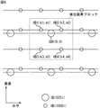
図2は、525i信号および1050i信号のあるフレーム(F)の画素位置関係を示すものであり、奇数(o)フィールドの画素位置を実線で示し、偶数(e)フィールドの画素位置を破線で示している。大きなドットが525i信号の画素であり、小さいドットが1050i信号の画素である。図2から分かるように、1050i信号の画素データとしては、525i信号のラインに近い位置のラインデータL1,L1′と、525i信号のラインから遠い位置のラインデータL2,L2′とが存在する。ここで、L1,L2は奇数フィールドのラインデータ、L1′,L2′は偶数フィールドのラインデータである。また、1050i信号の各ラインの画素数は、525i信号の各ラインの画素数の2倍である。
【0056】
図1に戻って、テレビジョン受信装置1の構成について説明する。ユーザは、リモートコマンダ2を用いて、テレビジョン受信装置1を操作する。テレビジョン受信装置1は、CPU(Central processing Unit)、RAM(Random Access Memory)、およびROM(Read Only memory)を含むマイクロコントローラを備え、システム全体の動作を制御するためのシステムコントローラ12と、リモートコントロール信号を受信する信号受信部11とを有している。信号受信部11は、システムコントローラ12に接続され、リモートコマンダ2よりユーザの操作に応じて出力されるリモートコントロール信号を受信し、その信号に対応する操作信号を、システムコントローラ12に供給するように構成されている。
【0057】
受信アンテナ3は、放送信号(RF変調信号)を受信する。チューナ13は、受信アンテナ3で捕らえられた放送信号の供給を受け、システムコントローラ12から入力される制御信号に従って、ユーザがリモートコマンダ2を用いて選局したチャンネルを選局する選局処理を行い、更に、中間周波増幅処理、検波処理等などを行って、上述したSD信号(525i信号)を得る。バッファメモリ14は、チューナ13より出力されるSD信号を一時的に保存する。
【0058】
持ち運び部15は、テレビジョン受信装置1から取り外して持ち運び可能なように構成されているか、あるいは、持ち運び部15を含む基板などが、テレビジョン受信装置1から取り外して持ち運び可能なように構成されている。持ち運び部15は、バッファメモリ14に一時的に保存されるSD信号(525i信号)を、HD信号(1050i信号)に変換する画像信号処理を行う。
【0059】
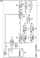
図3は、持ち運び部15の更に詳細な構成を示すブロック図である。
【0060】
持ち運び部15の第1のタップ選択部41、第2のタップ選択部42、および、第3のタップ選択部43は、バッファメモリ14に記憶されているSD信号(525i信号)より、HD信号(1050i信号)における注目位置の周辺に位置する複数のSD画素のデータを選択的に取り出して出力する。
【0061】
第1のタップ選択部41は、予測に使用するSD画素(以下、「予測タップ」と称する)のデータを選択的に取り出すものである。第2のタップ選択部42は、SD画素データのレベル分布パターンに対応するクラス分類に使用するSD画素(以下、「空間クラスタップ」と称する)のデータを選択的に取り出すものである。第3のタップ選択部43は、動きに対応するクラス分類に使用するSD画素(以下、「動きクラスタップ」と称する)のデータを選択的に取り出するものである。なお、空間クラスを複数フィールドに属するSD画素データを使用して決定する場合には、この空間クラスにも動き情報が含まれることになる。
【0062】
空間クラス検出部44は、第2のタップ選択部42で選択的に取り出された空間クラスタップのデータ(SD画素データ)のレベル分布パターンを検出し、このレベル分布パターンに基づいて空間クラスを検出し、そのクラス情報を出力する。
【0063】
空間クラス検出部44では、例えば、各SD画素データを、8ビットデータから2ビットデータに圧縮するような演算が行われる。そして、空間クラス検出部44からは、各SD画素データに対応した圧縮データが、空間クラスのクラス情報として出力される。本実施の形態においては、ADRC(Adaptive Dynamic Range Coding)によって、データ圧縮が行われる。なお、情報圧縮手段としては、ADRC以外にDPCM(予測符号化)、VQ(ベクトル量子化)等を用いてもよい。
【0064】
本来、ADRCは、VTR(Video Tape Recorder)向け高性能符号化用に開発された適応再量子化法であるが、信号レベルの局所的なパターンを短い語長で効率的に表現できるので、上述したデータ圧縮に使用して好適なものである。ADRCを使用する場合、空間クラスタップのデータ(SD画素データ)の最大値をMAX、その最小値をMIN、空間クラスタップのデータのダイナミックレンジをDR(=MAX−MIN+1)、再量子化ビット数をPとすると、空間クラスタップのデータとしての各SD画素データkiに対して、式(1)の演算により、圧縮データとしての再量子化コードqiが得られる。ただし、式(1)において、[ ]は切捨て処理を意味している。空間クラスタップのデータとして、Na個のSD画素データがあるとき、i=1乃至Naである。
【0065】
【数1】
![]()
![]()
動きクラス検出部45は、第3のタップ選択部43で選択的に取り出された動きクラスタップのデータ(SD画素データ)より、主に、動きの程度を表すための動きクラスを検出し、そのクラス情報を出力する。
【0067】
この動きクラス検出部45では、第3のタップ選択部43で選択的に取り出された動きクラスタップのデータ(SD画素データ)miおよびniからフレーム間差分が算出され、更に、その差分の絶対値の平均値に対してしきい値処理が行われて、動きの指標である動きクラスが検出される。すなわち、動きクラス検出部45は、式(2)によって、差分の絶対値の平均値AVを算出する。第3のタップ選択部43で、例えば、上述したように、12個のSD画素データm1乃至m6およびn1乃至n6が取り出されるとき、式(2)におけるNbは6である。
【0068】
【数2】

![]()
そして、動きクラス検出部45では、上述したように算出された平均値AVが、1個または複数個のしきい値と比較されて、動きクラスのクラス情報MVが得られる。例えば、3個のしきい値th1,th2,およびth3(th1<th2<th3)が用意され、4つの動きクラスが検出される場合、AV≦th1のときはMV=0、th1<AV≦th2のときはMV=1、th2<AV≦th3のときはMV=2、th3<AVのときはMV=3とされる。
【0070】
クラス合成部46は、空間クラス検出部44より出力される空間クラスのクラス情報としての再量子化コードqiと、動きクラス検出部45より出力される動きクラスのクラス情報MVに基づき、作成すべきHD信号(1050i信号)の画素データ(注目位置の画素データ)が属するクラスを示すクラスコードCLを得る。
【0071】
このクラス合成部46では、式(3)によって、クラスコードCLの演算が行われる。なお、式(3)において、Naは空間クラスタップのデータ(SD画素データ)の個数、PはADRCにおける再量子化ビット数を示している。
【0072】
【数3】
![]()
係数メモリ53は、後述する推定予測演算部47で使用される推定式で用いられる複数の係数データWiを、クラス毎に格納するものである。この係数データWiは、SD信号(525i信号)を、HD信号(1050i信号)に変換するための情報である。係数メモリ53には、クラス合成部46より出力されるクラスコードCLが、読み出しアドレス情報として供給され、係数メモリ53からは、クラスコードCLに対応した推定式の係数データWi(i=1乃至n)が読み出され、推定予測演算部47に供給される。
【0074】
また、持ち運び部15は、情報メモリバンク51を有している。後述する推定予測演算部47では、予測タップのデータ(SD画素データ)xiと、係数メモリ53より読み出される係数データWiとから、式(4)の推定式によって、作成すべきHD画素データyが演算される。式(4)のnは、第1のタップ選択部41で選択される予測タップの数を表している。
【0075】
ここで、タップ選択部41で選択的に取り出された予測タップのn個の画素データの位置は、HD信号における注目位置に対して、空間方向(水平、垂直の方向)および時間方向に亘っている。
【0076】
【数4】
![]()
そして、推定式の係数データWi(i=1乃至n)は、式(5)に示すように、パラメータs、およびzを含む生成式によって生成される。情報メモリバンク51は、この生成式における係数データである係数種データw10乃至wn9を、クラス毎に格納する。この係数種データの生成方法については後述する。
【0078】
【数5】
![]()
上述したように、525i信号を1050i信号に変換する場合、奇数、および偶数のそれぞれのフィールドにおいて、525i信号の1画素に対応して1050i信号の4画素を得る必要がある。この場合、奇数、偶数のそれぞれのフィールドにおける1050i信号を構成する2×2の単位画素ブロック内の4画素は、それぞれ中心予測タップに対して異なる位相ずれを持っている。
【0080】
図4は、奇数フィールドにおける1050i信号を構成する2×2の単位画素ブロック内の4画素HD1乃至HD4における中心予測タップSD0からの位相ずれを示している。ここで、HD1乃至HD4の位置は、それぞれ、SD0の位置から水平方向にk1乃至k4、垂直方向にm1乃至m4だけずれている。
【0081】
図5は、偶数フィールドにおける1050i信号を構成する2×2の単位画素ブロック内の4画素HD1′乃至HD4′における中心予測タップSD0′からの位相ずれを示している。ここで、HD1′乃至HD4′の位置は、それぞれ、SD0′の位置から水平方向にk1′乃至k4′、垂直方向にm1′乃至m4′だけずれている。
【0082】
従って、情報メモリバンク51には、クラスおよび出力画素(HD1乃至HD4,HD1′乃至HD4′)の組合わせ毎に、係数種データw10乃至wn9が格納されている。
【0083】
係数生成部52は、各クラスの係数種データ、並びに、パラメータs、およびzの値を用い、式(5)によって、クラス毎に、パラメータs、およびzの値に対応した推定式の係数データWi(i=1乃至n)を生成する。係数生成部52には、情報メモリバンク51より、上述した各クラスの係数種データがロードされる。また、係数生成部52には、システムコントローラ12より、パラメータs、およびzの値が供給される。
【0084】
係数生成部52で生成される各クラスの係数データWi(i=1乃至n)は、上述した係数メモリ53に格納される。この係数生成部52における各クラスの係数データWiの生成は、例えば、各垂直ブランキング期間で行われる。これにより、ユーザのリモートコマンダ2の操作によってパラメータs、およびzの値が変更されても、係数メモリ53に格納される各クラスの係数データWiを、そのパラメータs、およびzの値に対応したものに即座に変更することができ、ユーザによる解像度の調整がスムーズに行われる。
【0085】
正規化係数演算部54は、係数生成部52で求められた係数データWi(i=1乃至n)に対応した正規化係数Sを、式(6)によって演算する。正規化係数メモリ55は、この正規化係数Sを格納する。正規化係数メモリ55には、上述したクラス合成部46より出力されるクラスコードCLが、読み出しアドレス情報として供給され、正規化係数メモリ55からは、クラスコードCLに対応した正規化係数Sが読み出され、後述する正規化演算部48に供給される。
【0086】
【数6】
![]()
推定予測演算部47は、第1のタップ選択部41で選択的に取り出された予測タップのデータ(SD画素データ)xiと、係数メモリ53より読み出される係数データWiとから、式(4)の推定式によって、作成すべきHD信号の画素データ(注目位置の画素データ)を演算する。
【0088】
上述したように、SD信号(525i信号)をHD信号(1050i信号)に変換する際には、SD信号の1画素に対してHD信号の4画素(図4のHD1乃至HD4、図5のHD1′乃至HD4′参照)を得る必要があることから、この推定予測演算部47では、HD信号を構成する2×2の単位画素ブロック毎に、画素データが生成される。すなわち、この推定予測演算部47には、第1のタップ選択部41より単位画素ブロック内の4画素(注目画素)に対応した予測タップのデータxiと、係数メモリ53よりその単位画素ブロックを構成する4画素に対応した係数データWiとが供給され、単位画素ブロックを構成する4画素のデータy1乃至y4は、それぞれ個別に、上述した式(4)の推定式で演算される。
【0089】
正規化演算部48は、推定予測演算部47より順次出力される4画素のデータy1乃至y4を、正規化係数メモリ55より読み出される、それぞれの演算に使用された係数データWi(i=1乃至n)に対応した正規化係数Sで除算して正規化する。上述したように、係数生成部52は、推定式の係数データWiを求めるものであるが、求められる係数データは丸め誤差を含み、係数データWi(i=1乃至n)の総和が1.0になることは保証されない。そのため、推定予測演算部47で演算される各画素のデータy1乃至y4は、丸め誤差によってレベル変動したものとなる。従って、正規化演算部48で正規化することで、そのレベル変動を除去することができる。
【0090】
後処理部49は、正規化演算部48で正規化されて順次供給される単位画素ブロック内の4画素のデータy1′乃至y4′を線順次化して、1050i信号のフォーマットで出力する。
【0091】
履歴情報記憶部50は、システムコントローラ12から係数生成部52に入力されるパラメータs、およびzの値の履歴情報を格納する。
【0092】
図6は、履歴情報記憶部50の更に詳細な構成を示すブロック図である。履歴情報記憶部50は、システムコントローラ12から係数生成部52に入力されるパラメータs、およびzの値のそれぞれの度数分布の情報を格納する度数分布メモリ91を備えている。度数分布メモリ91には、パラメータs、およびzの各値における度数が平均化されて格納される。この度数分布メモリ91は、例えば、不揮発性のメモリで構成され、テレビジョン受信装置1の電源がオフの状態となっても、その記憶内容が保持されるようになされている。
【0093】
そのために、履歴情報記憶部50は、更に、パラメータs、およびzの値の係数生成部52への入力回数をカウントするカウンタ92と、このカウンタ92のカウント値に基づいて、パラメータs、およびzの値における度数を平均化する平均化部93とを備えている。
【0094】
カウンタ92のカウントアップは、システムコントローラ12の制御によって行われる。ユーザは、図7および図8を用いて後述するように、調整画面上でパラメータs、およびzの値を調整し得るが、カウンタ92はその調整が終了した時点でカウントアップされる。
【0095】
平均化部93は、入力されたパラメータs、およびzの値、カウンタ92のカウント値および度数分布メモリ91に格納されている前回までのパラメータs、およびzの各値における度数の平均値を用いて、パラメータs、およびzの各値における新たな度数の平均値を求める。
【0096】
この場合、入力回数がM、つまりカウンタ92のカウント値がMとなるとき、入力されるパラメータの値における度数に関しては、前回までのそのパラメータにおける度数の平均値をnM-1とするとき、新たな度数の平均値nMは、次の式(7)の演算により求められる。一方、入力回数がMであるとき、入力されるパラメータの値とは異なるパラメータの値における度数に関しては、前回までのそのパラメータにおける度数の平均値をnM-1とするとき、新たな度数の平均値nMは、次の式(8)の演算により求められる。
【0097】
【数7】
![]()
![]()
【数8】
![]()
![]()
このように、度数分布メモリ91に格納されるパラメータs、およびzの値の度数分布の情報として、パラメータs、およびzの各値における度数の平均値を用いることで、オーバーフローを防止することができる。
【0100】
なお、パラメータs、およびzの各値における度数の平均値を用いる変わりに、パラメータs、およびzの各値における度数を、最大度数によって正規化した値を用いるようにしても、同様にオーバーフローを防止できる。
【0101】
また、履歴情報記憶部50は、システムコントローラ12から係数生成部52に入力されるパラメータs、およびzの値のうち、所定数、例えば10個の最新のパラメータs、およびzの値を格納する経時変化メモリ94を有している。この経時変化メモリ94は、例えば、不揮発性のメモリで構成され、テレビジョン受信装置1の電源がオフの状態でもその記憶内容が保持されるようになされている。
【0102】
経時変化メモリ94への書き込み動作は、システムコントローラ12の制御によって行われる。図7および図8を用いて後述するように、ユーザは、調整画面上でパラメータs、およびzの値を調整することができるが、経時変化メモリ94には、その調整が終了した時点で、新たなパラメータs、およびzの値が書き込まれる。この書き込みに伴って、格納されているパラメータs、およびzの値の個数が所定数を越えるときは、最も古いパラメータs、およびzの値が削除される。
【0103】
また、テレビジョン受信装置1において、持ち運び部15、もしくは、持ち運び部15を含む、例えば、基板などのユニットは、装脱可能に構成されているので、持ち運び部15を外部に持ち出して利用したり、持ち運び部15を交換したりすることによって、テレビジョン受信装置1の機能のバージョンアップを行うこと等が可能になっている。これにより、履歴情報記憶部50は持ち運び部15とともに装脱されることとなる。
【0104】
なお、持ち運び部15全体を着脱可能に構成するのではなく、履歴情報記憶部50、あるいは度数分布メモリ91、経時変化メモリ94のみが装脱可能に構成されていてもよい。
【0105】
図1に戻り、再び、テレビジョン受信装置1の構成について説明する。
【0106】
OSD(On Screen Display)処理部16は、表示部18の画面上に文字図形などの表示を行うための表示信号SCHを発生する。合成部17は、OSD処理部16から出力される表示信号SCHを、持ち運び部15から出力されるHD信号に合成して、表示部18に供給する。表示部18は、例えば、CRT(cathode-ray tube)ディスプレイ、あるいはLCD(liquid crystal display)等のフラットパネルディスプレイで構成され、持ち運び部15より出力されるHD信号による画像と、必要に応じて合成部17により合成された表示信号SCHとを表示する。
【0107】
また、システムコントローラ12には、必要に応じてドライブ19が接続され、磁気ディスク21、光ディスク22、光磁気ディスク23、あるいは、半導体メモリ24などが適宜装着され、それらから読み出されたコンピュータプログラムが、必要に応じてシステムコントローラ12にインストールされる。
【0108】
図1のテレビジョン受信装置1の動作について説明する。
【0109】
システムコントローラ12は、リモートコマンダ2を用いて入力されるユーザの操作に基づいて、チューナ13を制御する。チューナ13は、システムコントローラ12の制御に従って、アンテナ3で受信された放送信号に対して、選局処理、中間周波増幅処理、および検波処理などを行い、バッファメモリ14に出力する。
【0110】
チューナ13より出力されるSD信号(525i信号)は、バッファメモリ14に供給されて、一時的に保存される。そして、バッファメモリ14に一時的に記憶されたSD信号は、持ち運び部15に供給され、システムコントローラ12から供給される制御信号を基に、HD信号(1050i信号)に変換される。
【0111】
すなわち、持ち運び部15では、SD信号を構成する画素データ(以下、「SD画素データ」と称する)から、HD信号を構成する画素データ(以下、「HD画素データ」と称する)を得ることができる。持ち運び部15より出力されるHD信号は、必要に応じて、合成部17において、OSD処理部16から出力される表示信号SCHによる文字図形などと合成されて、表示部18に供給され、表示部18の画面上に、画像が表示される。
【0112】
また、ユーザは、リモートコマンダ2の操作によって、表示部18の画面上に表示される画像の空間方向および時間方向の解像度を調整することができる。持ち運び部15では、推定式によって、HD画素データが算出されるが、この推定式の係数データとして、ユーザのリモートコマンダ2の操作によって調整された、空間方向、および時間方向の解像度を定めるパラメータs、およびzに対応したものが、これらパラメータs、およびzを含む生成式によって生成されて使用される。これにより、持ち運び部15から出力されるHD信号による画像の空間方向、および時間方向の解像度は、調整されたパラメータs、およびzに対応したものとなる。
【0113】
図7は、パラメータs、およびzを調整するためのユーザインターフェースの一例を示している。調整時には、表示部18に、パラメータs、およびzの調整位置を、図中星印のアイコン72で示した調整画面71が、OSD表示される。また、リモートコマンダ2は、ユーザ操作手段としてのジョイスティック81を備えている。
【0114】
ユーザは、ジョイスティック81を操作することで、調整画面71上でアイコン72の位置を動かすことができ、空間方向、時間方向の解像度を決定するパラメータs、およびzの値を調整することができる。
【0115】
図8に、図7の調整画面71の部分を拡大して示す。アイコン72が左右に動かされることで時間方向の解像度(時間解像度)を決定するパラメータzの値が調整され、一方アイコン72が上下に動かされることで空間方向の解像度(空間解像度)を決定するパラメータsの値が調整される。ユーザは、表示部18に表示される調整画面71を参照して、パラメータs、およびzの値の調整を容易に行うことができる。
【0116】
なお、リモートコマンダ2は、ジョイスティック81の代わりに、マウスやトラックボール等のその他のポインティングデバイスを備えるようにしてもよい。更に、ユーザによって調整されたパラメータs、およびzの値が、調整画面71上に数値表示されるようにしてもよい。
【0117】
次に、図3を用いて説明した持ち運び部15の動作を説明する。
【0118】
第2のタップ選択部42は、バッファメモリ14に記憶されているSD信号(525i信号)の供給を受け、作成すべきHD信号(1050i信号)を構成する単位画素ブロック内の4画素(注目位置の画素)の周辺に位置する空間クラスタップのデータ(SD画素データ)を、選択的に取り出す。第2のタップ選択部42で選択的に取り出された空間クラスタップのデータ(SD画素データ)は、空間クラス検出部44に供給される。空間クラス検出部44は、空間クラスタップのデータとしての各SD画素データに対して、ADRC処理を施して、空間クラス(主に空間内の波形表現のためのクラス分類)のクラス情報としての再量子化コードqiを得る(式(1)参照)。
【0119】
また、第3のタップ選択部43は、バッファメモリ14に記憶されているSD信号(525i信号)の供給を受け、作成すべきHD信号(1050i信号)を構成する単位画素ブロック内の4画素(注目位置の画素)の周辺に位置する動きクラスタップのデータ(SD画素データ)を選択的に取り出す。第3のタップ選択部43で選択的に取り出された動きクラスタップのデータ(SD画素データ)は、動きクラス検出部45に供給される。動きクラス検出部45は、動きクラスタップのデータとしての各SD画素データより、動きクラス(主に動きの程度を表すためのクラス分類)のクラス情報MVを得る。
【0120】
この動き情報MVと、再量子化コードqiとは、クラス合成部46に供給される。クラス合成部46は、供給された動き情報MVと再量子化コードqiとから、作成すべきHD信号(1050i信号)を構成する単位画素ブロック毎に、その単位画素ブロック内の4画素(注目画素)が属するクラスを示すクラスコードCLを得る(式(3)参照)。そして、このクラスコードCLは、係数メモリ53および正規化係数メモリ55に、読み出しアドレス情報として供給される。
【0121】
例えば、各垂直ブランキング期間に、係数生成部52で、ユーザによって調整されたパラメータs、およびzの値に対応して、クラスおよび出力画素(HD1乃至HD4,HD1′乃至HD4′)の組合わせ毎に、係数種データw10乃至wn9を用いて、推定式の係数データWi(i=1乃至n)が求められて、係数メモリ53に格納される(式(5)参照)。また、係数生成部52で求められた推定式の係数データWi(i=1乃至n)に対応した正規化係数Sが、正規化係数演算部54で生成されて、正規化係数メモリ55に格納される(式(6)参照)。
【0122】
クラスコードCLが、係数メモリ53に読み出しアドレス情報として供給されることで、この係数メモリ53からクラスコードCLに対応した4出力画素(奇数フィールドではHD1乃至HD4、偶数フィールドではHD1′乃至HD4′)分の推定式の係数データWiが読み出されて、推定予測演算部47に供給される。また、第1のタップ選択部41は、バッファメモリ14に記憶されているSD信号(525i信号)の供給を受け、作成すべきHD信号(1050i信号)を構成する単位画素ブロック内の4画素(注目位置の画素)の周辺に位置する予測タップのデータ(SD画素データ)を選択的に取り出す。
【0123】
推定予測演算部47は、予測タップのデータ(SD画素データ)xiと、係数メモリ53より読み出される4出力画素分の係数データWiとから、作成すべきHD信号を構成する単位画素ブロック内の4画素(注目位置の画素)のデータy1乃至y4を演算する(式(4)参照)。そして、この推定予測演算部47より順次出力されるHD信号を構成する単位画素ブロック内の4画素のデータy1乃至y4は、正規化演算部48に供給される。
【0124】
正規化係数メモリ55には、上述したように、クラスコードCLが読み出しアドレス情報として供給され、正規化係数メモリ55からはクラスコードCLに対応した正規化係数S、つまり、推定予測演算部47より出力されるHD画素データy1乃至y4の演算に使用された係数データWiに対応した正規化係数Sが読み出されて、正規化演算部48に供給される。正規化演算部48は、推定予測演算部47より出力されるHD画素データy1乃至y4を、それぞれ対応する正規化係数Sで除算して正規化する。これにより、係数生成部52で係数データWiを求める際の丸め誤差によるデータy1乃至y4のレベル変動が除去される。
【0125】
このように、正規化演算部48で正規化されて順次出力される単位画素ブロック内の4画素のデータy1′乃至y4′は、後処理部49に供給される。後処理部49は、正規化演算部48より順次供給される単位画素ブロック内の4画素のデータy1′乃至y4′を線順次化し、1050i信号のフォーマットで出力する。つまり、後処理部49からは、HD信号としての1050i信号が出力される。
【0126】
このように、持ち運び部15は、調整されたパラメータs、およびzの値に対応した推定式の係数データWi(i=1乃至n)を用いて、HD画素データyを演算するものである。従って、ユーザは、パラメータs、およびzの値を調整することで、HD信号による画像の空間方向および時間方向の解像度を自由に調整することができる。また、調整されたパラメータs、およびzの値に対応した各クラスの係数データは、その都度、係数生成部52で生成されて使用されるものであるので、大量の係数データを格納しておくメモリは必要なくなり、メモリの節約を図ることができる。
【0127】
また、上述したように、ユーザは、調整画面71上でパラメータs、およびzの値を調整することができる。履歴情報記憶部50の度数分布メモリ91(図6参照)には、システムコントローラ12から係数生成部52に入力されるパラメータs、およびzの値のそれぞれの度数分布の情報が格納される。また、履歴情報記憶部50の経時変化メモリ94(図6参照)には、システムコントローラ12から係数生成部52に入力されるパラメータs、およびzの値のうち、所定数、例えば、10個の最新のパラメータs、およびzの値が格納される。
【0128】
このように、履歴情報記憶部50の度数分布メモリ91、および経時変化メモリ94に格納される履歴情報は、例えば、テレビジョン受信装置1のバージョンアップ時に、持ち運び部15、もしくは持ち運び部15が含まれる基板を取り換える場合や、持ち運び部15を他の装置に装着して利用する場合において、その情報メモリバンク51に格納される係数種データw10乃至wn9を生成する際などに利用される。
【0129】
次に、係数種データw10乃至wn9の生成方法の一例について説明する。この例においては、上述した式(5)の生成式における係数データである係数種データw10乃至wn9を求める例を示すものとする。
【0130】
ここで、以下の説明のため、式(9)のように、ti(i=0乃至9)を定義する。
【0131】
【数9】
![]()
【0132】
【数10】
![]()
最終的に、学習によって未定係数wijが求められる。すなわち、クラスおよび出力画素の組合わせ毎に、複数のSD画素データとHD画素データを用いて、二乗誤差を最小にする係数値が決定される。これは、いわゆる、最小二乗法による解法である。学習数をm、k(1≦k≦m)番目の学習データにおける残差をek、二乗誤差の総和をEとすると、式(4)および式(5)を用いて、Eは式(11)で表される。ここで、xikはSD画像のi番目の予測タップ位置におけるk番目の画素データ、ykはそれに対応するk番目のHD画像の画素データを表している。
【0134】
【数11】
![]()
最小二乗法による解法では、式(11)のwijによる偏微分が0になるようなwijを求める。これは、式(12)で示される。
【0136】
【数12】
![]()
以下、式(13)、式(14)のように、Xipjq、Yipを定義すると、式(12)は、式(15)のように行列を用いて書き換えられる。
【0138】
【数13】
![]()
【数14】
![]()
【数15】
![]()
この方程式は、一般に、正規方程式と称されている。正規方程式は、掃き出し法(Gauss-Jordanの消去法)等を用いて、wijについて解かれ、係数種データが算出される。
【0142】
図9は、上述した係数種データの生成方法の一例の概念を示す図である。
【0143】
HD信号から、複数のSD信号が生成される。例えば、HD信号からSD信号を生成する際に使用されるフィルタの空間方向(垂直方向および水平方向)の帯域と時間方向(フレーム方向)の帯域を可変するパラメータs、およびzをそれぞれ9段階に可変することによって、合計81種類のSD信号が生成される。このようにして生成された複数のSD信号とHD信号との間で、学習が行われて、係数種データが生成される。
【0144】
図10は、上述したテレビジョン受信装置1の情報メモリバンク51に格納される係数種データw10乃至wn9を生成するための、係数種データ生成装置121の構成を示すブロック図である。
【0145】
入力端子141には、教師信号としてのHD信号(1050i信号)が入力される。SD信号生成部143は、このHD信号に対して、入力端子142から入力される履歴情報、並びに、パラメータs、およびzの値を用いて、水平および垂直の間引き処理を行って、生徒信号としてのSD信号を得る。
【0146】
SD信号生成部143は、入力端子142から入力されるパラメータs、およびzに基づいて、HD信号からSD信号を生成する際に用いられる帯域制限フィルタの、空間方向および時間方向の帯域を変更する。
【0147】
また、このSD信号生成部143に入力される履歴情報は、履歴情報記憶部50の度数分布メモリ91、経時変化メモリ94に格納されている、入力されたパラメータs、およびzの値の履歴情報である。
【0148】
なお、使用開始前のテレビジョン受信装置1の情報メモリバンク51に格納される係数種データw10乃至wn9を生成する際には、いまだ履歴情報記憶部50の度数分布メモリ91、経時変化メモリ94に履歴情報が格納されていないので、SD信号生成部143に履歴情報は入力されない。
【0149】
つまり、SD信号生成部143に履歴情報が入力されるのは、例えば、テレビジョン受信装置1のバージョンアップ時に持ち運び部15、もしくは持ち運び部15が含まれる基板を取り換える場合などであって、その情報メモリバンク51に格納される係数種データw10乃至wn9を生成する際などである。
【0150】
ここで、入力端子142には、図3を用いて説明した持ち運び部15において、システムコントローラ12と接続され、履歴情報記憶部50と情報が授受可能になされている接続端子が接続されるようにすればよい。すなわち、入力端子142の端子161および端子162は、履歴情報記憶部50と接続されて、履歴情報の入力を受け、情報の授受が可能である。
【0151】
SD信号生成部143では、履歴情報に基づいて、入力されたパラメータs、およびzの値が調整され、この調整されたパラメータs、およびzの値に応じて、空間方向および時間方向の帯域が可変される。履歴情報の入力がないときは、入力されたパラメータs、およびzの値そのものに応じて、空間方向および時間方向の帯域が可変される。
【0152】
ここで、テレビジョン受信装置1では、ユーザの操作によって、パラメータs、およびzの値が、例えばそれぞれ0乃至8の範囲内で、所定のステップをもって調整され、空間方向および時間方向の解像度の調整が行われていた。
【0153】
この場合、SD信号生成部143において入力されるパラメータs、およびzの値そのものに応じて空間方向および時間方向の帯域が可変されるとき、テレビジョン受信装置1では、図11に実線枠BFで示す範囲(空間解像度はy1乃至y2、時間解像度はx1乃至x2)内で解像度の調整を行い得るように、係数種データw10乃至wn9が生成される。
【0154】
履歴情報が入力される場合、SD信号生成部143では、パラメータs、およびzの値のそれぞれにおける度数分布の情報が用いられて重心位置が求められる。この場合、所定数の最新のパラメータs、およびzの値に対応する値のうち新しい値ほど大きな重み付けがされる。そして、SD信号生成部143では、この重心位置に基づいて、入力されるパラメータs、およびzの値が調整される。この場合、パラメータs、およびzの値が大きくなるほど帯域が狭くなるようにされる。これにより、調整されたパラメータを得たテレビジョン受信装置1では、パラメータs、およびzの値が大きくされるほど解像度が上がるように調整されるようになる。
【0155】
ここでは、テレビジョン受信装置1側で調整されるパラメータs、およびzの値の変化範囲の中心が、求められた重心位置に移動するように、入力されるパラメータs、およびzの値が線形変換されるようになされている。例えば、テレビジョン受信装置1側で調整されるパラメータs、およびzの値の変化範囲の中心値がs0,z0、求められる重心位置がsm,zm、入力されるパラメータs、およびzの値がs1,z1であるとき、調整後のパラメータs、およびzの値s2,z2は、次の変換式で求められる。
【0156】
【数16】
![]()
![]()
【数17】
![]()
![]()
このように調整されたパラメータs、およびzの値に応じて、空間方向および時間方向の帯域が可変される場合、テレビジョン受信装置1では、図11に実線枠BFで示す範囲内の解像度調整位置(「×」印で図示)の重心位置を中心とする、図11の一点鎖線枠AFで示す範囲(空間解像度はy1′乃至y2′、時間解像度はx1′乃至x2′)内で解像度の調整を行い得るように、係数種データw10乃至wn9が生成される。
【0159】
なお、上述した処理では、パラメータs、およびzの値のそれぞれにおける度数分布の情報を用いて重心位置を求める際に、所定数の最新のパラメータs、およびzの値に対応する値のうち、新しい値ほど大きな重み付けがされるものであったが、このような重み付けがされずに求められる重心位置を使用するようにしてもよい。また、度数分布の情報は用いずに、所定数の最新のパラメータs、およびzの値を用い、新しい値ほど大きな重み付けがされて求められた重心位置を使用するようにしてもよい。更には、パラメータs、およびzの値のそれぞれにおける度数分布の情報から最も度数の大きなパラメータs、およびzの値を求め、その値を重心位置の代わりに使用するようにしてもよい。また、所定数の最新のパラメータs、およびzの値のうち、最も新しいパラメータs、およびzの値を、重心位置の代わりに使用するようにしてもよい。
【0160】
図10に戻って、再び、係数種データ生成装置121の構成について説明する。
【0161】
第1のタップ選択部144、第2のタップ選択部145、および第3のタップ選択部146は、SD信号生成部143より出力されるSD信号(525i信号)より、HD信号(1050i信号)における注目位置の周辺に位置する複数のSD画素のデータを選択的に取り出して出力する。これら第1のタップ選択部144乃至第3のタップ選択部146は、図3を用いて説明した持ち運び部15の第1のタップ選択部41乃至第3のタップ選択部43と、基本的に同様に構成される。
【0162】
空間クラス検出部147は、第2のタップ選択部145で選択的に取り出された空間クラスタップのデータ(SD画素データ)のレベル分布パターンを検出し、このレベル分布パターンに基づいて空間クラスを検出し、そのクラス情報を出力する。この空間クラス検出部147は、図3を用いて説明した持ち運び部15の空間クラス検出部44と基本的に同様に構成される。この空間クラス検出部147からは、空間クラスタップのデータとしての各SD画素データの再量子化コードqiが、空間クラスを示すクラス情報として出力される。
【0163】
動きクラス検出部148は、第3のタップ選択部146で選択的に取り出された動きクラスタップのデータ(SD画素データ)より、主に動きの程度を表すための動きクラスを検出し、そのクラス情報MVを出力する。この動きクラス検出部148は、図3を用いて説明した持ち運び部15の動きクラス検出部45と基本的に同様に構成される。この動きクラス検出部148では、第3のタップ選択部146で選択的に取り出された動きクラスタップのデータ(SD画素データ)からフレーム間差分が算出され、更に、その差分の絶対値の平均値に対してしきい値処理が行われて、動きの指標である動きクラスが検出される。
【0164】
クラス合成部149は、空間クラス検出部147より出力される空間クラスのクラス情報としての再量子化コードqiと、動きクラス検出部148より出力される動きクラスのクラス情報MVとに基づき、HD信号(1050i信号)に係る注目画素が属するクラスを示すクラスコードCLを得る。このクラス合成部149も、図3を用いて説明した持ち運び部15のクラス合成部46と基本的に同様に構成される。
【0165】
正規方程式生成部150は、入力端子141に供給されるHD信号から得られる注目位置の画素データとしての各HD画素データy、この各HD画素データyにそれぞれ対応して第1のタップ選択部144で選択的に取り出された予測タップのデータ(SD画素データ)xi、パラメータsおよびzの値、並びに、各HD画素データyにそれぞれ対応してクラス合成部149より出力されるクラスコードCLとから、クラス毎に、係数種データw10乃至wn9を得るための正規方程式(式(15)参照)を生成する。
【0166】
この場合、1個のHD画素データyと、それに対応するn個の予測タップのデータ(SD画素データ)xiとの組合わせで、学習データが生成されるが、調整後のパラメータs、およびzの値の変化に対応して、SD信号生成部143における空間方向および時間方向の帯域が可変され、複数のSD信号が順次生成されて、HD信号と各SD信号との間でそれぞれ学習データの生成が行われる。これにより、正規方程式生成部150では、パラメータs、およびzの値が異なる多くの学習データが登録された正規方程式が生成され、係数種データw10乃至wn9を求めることが可能となる。
【0167】
また、この場合、1個のHD画素データyとそれに対応するn個の予測タップのデータ(SD画素データ)xiとの組合わせで学習データが生成されるが、正規方程式生成部150では、出力画素(図4のHD1乃至HD4、図5のHD1′乃至HD4′参照)毎に、正規方程式が生成される。例えば、HD1に対応した正規方程式は、中心予測タップに対するずれ値がHD1と同じ関係にあるHD画素データyから構成される学習データから生成される。
【0168】
係数種データ決定部151は、正規方程式生成部150で、クラスおよび出力画素の組合わせ毎に生成された正規方程式のデータの供給を受け、正規方程式を解いて、クラスおよび出力画素の組合わせ毎に、係数種データw10乃至wn9を求める。係数種データ決定部151は、正規方程式を、例えば、掃き出し法などによって解くことにより、係数種データを求める。係数種メモリ152は、係数種データ決定部151で求められた係数種データを格納する。入出力インターフェース153は、必要に応じて、他の機器(例えば、図3を用いて説明した持ち運び部15の情報メモリバンク51)と接続され、係数種メモリ152に格納されている係数種データを出力する。
【0169】
次に、図10の係数種データ生成装置121の動作について説明する。
【0170】
入力端子141には、教師信号としてのHD信号(1050i信号)が供給され、そしてこのHD信号に対して、SD信号生成部143で、水平および垂直の間引き処理が行われて、生徒信号としてのSD信号(525i信号)が生成される。
【0171】
この場合、SD信号生成部143には、HD信号からSD信号を生成する際に用いられる帯域制限フィルタの空間方向および時間方向の帯域を定めるパラメータ、換言すれば、生成されるSD信号の空間方向および時間方向の解像度を定めるパラメータs、およびzの値が入力される。
【0172】
また、SD信号生成部143には、例えば、テレビジョン受信装置1のバージョンアップ時に、持ち運び部15、もしくは持ち運び部15が含まれる基板を取り換える場合など、その情報メモリバンク51に格納される係数種データw10乃至wn9を生成する際には、取り換え前の持ち運び部15、もしくは持ち運び部15が含まれる基板における履歴情報記憶部50の度数分布メモリ91、経時変化メモリ94に格納されている、ユーザ操作によって過去に入力されたパラメータs、およびzの履歴情報が、入力端子142を介して入力される。
【0173】
SD信号生成部143では、履歴情報が入力されるときは、この履歴情報に基づいて入力されたパラメータs、およびzの値が調整される。例えば、履歴情報によってパラメータs、およびzの重心位置が求められ、テレビジョン受信装置1側で調整されるパラメータs、およびzの値の変化範囲の中心が、求められた重心位置に移動するように、入力されるパラメータs、およびzの値が線形変換される。そして、SD信号生成部143では、調整されたパラメータs、およびzの値に応じて、上述したように、HD信号からSD信号を生成する際に用いられる帯域制限フィルタの空間方向および時間方向の帯域が可変される。
【0174】
なお、使用開始前のテレビジョン受信装置1の情報メモリバンク51に格納される係数種データw10乃至wn9を生成する際には、履歴情報の入力がないので、入力されたパラメータs、およびzの値そのものに応じて、上述したようにHD信号からSD信号を生成する際に用いられる帯域制限フィルタの空間方向および時間方向の帯域が可変される。
【0175】
SD信号生成部143に入力されるパラメータs、およびzの値が順次変更されることで、HD信号からSD信号を生成する際に用いられる帯域制限フィルタの空間方向および時間方向の帯域が変更されることから、空間方向および時間方向の帯域が段階的に変化した複数のSD信号が生成される。
【0176】
また、SD信号生成部143で生成されたSD信号(525i信号)より、第2のタップ選択部145で、HD信号(1050i信号)における注目位置の周辺に位置する空間クラスタップのデータ(SD画素データ)が選択的に取り出される。この第2のタップ選択部145で選択的に取り出された空間クラスタップのデータ(SD画素データ)は、空間クラス検出部147に供給される。空間クラス検出部147では、空間クラスタップのデータとしての各SD画素データに対してADRC処理が施されて、空間クラス(主に空間内の波形表現のためのクラス分類)のクラス情報としての再量子化コードqiが得られる(式(1)参照)。
【0177】
また、SD信号生成部143で生成されたSD信号より、第3のタップ選択部146で、HD信号に係る注目画素の周辺に位置する動きクラスタップのデータ(SD画素データ)が選択的に取り出される。この第3のタップ選択部146で選択的に取り出された動きクラスタップのデータ(SD画素データ)は、動きクラス検出部148に供給される。この動きクラス検出部148では、動きクラスタップのデータとしての各SD画素データより動きクラス(主に動きの程度を表すためのクラス分類)のクラス情報MVが得られる。
【0178】
クラス情報MVと再量子化コードqiとは、クラス合成部149に供給される。クラス合成部149は、供給されたクラス情報MVと再量子化コードqiとから、HD信号(1050i信号)における注目位置の画素データが属するクラスを示すクラスコードCLを得る(式(3)参照)。
【0179】
また、SD信号生成部143で生成されるSD信号より、第1のタップ選択部144で、HD信号における注目位置の周辺に位置する予測タップのデータ(SD画素データ)が選択的に取り出される。
【0180】
そして、正規方程式生成部150では、入力端子141に供給されるHD信号より得られる注目位置の画素データとしての各HD画素データyと、この各HD画素データyにそれぞれ対応して第1のタップ選択部144で選択的に取り出された予測タップのデータ(SD画素データ)xiと、パラメータs、およびzの値と、各HD画素データyにそれぞれ対応してクラス合成部149より出力されるクラスコードCLとから、クラスおよび出力画素の組合わせ毎に、係数種データw10乃至wn9を得るための正規方程式(式(15)参照)が個別に生成される。
【0181】
そして、係数種データ決定部151で各正規方程式が解かれ、クラスおよび出力画素の組合わせ毎の係数種データw10乃至wn9が求められ、それらの係数種データw10乃至wn9は、係数種メモリ152に格納され、必要に応じて、入出力インターフェース153を介して、外部に出力される。
【0182】
このように、図10に示す係数種データ生成装置121においては、図1の持ち運び部15の情報メモリバンク51に格納される、クラスおよび出力画素(HD1乃至HD4,HD1′乃至HD4′)の組合わせ毎の、推定式で用いられる係数データWiを求めるための生成式(式(5)参照)における係数データである係数種データw10乃至wn9を生成することができる。
【0183】
また、この係数種データ生成装置121において、例えば、テレビジョン受信装置1のバージョンアップ時に、持ち運び部15、もしくは持ち運び部15が含まれる基板を取り換える場合であって、その情報メモリバンク51に格納される係数種データw10乃至wn9を生成する際には、入力端子142を介して、SD信号生成部143に、テレビジョン受信装置1の履歴情報記憶部50の度数分布メモリ91、経時変化メモリ94に格納されている、ユーザ操作によって過去に入力されたパラメータs、およびzの履歴情報が入力される。
【0184】
SD信号生成部143では、この履歴情報に基づいて、入力されるパラメータs、およびzの値が調整され、この調整されたパラメータs、およびzによって、HD信号からSD信号を得る際に用いられる帯域制限フィルタの空間方向および時間方向の帯域が可変される。
【0185】
このようにして求められた係数種データw10乃至wn9を、テレビジョン受信装置1のバージョンアップ時に新たに装着される持ち運び部15、もしくは持ち運び部15が含まれる基板の情報メモリバンク51に格納して使用することで、ユーザは、パラメータs、およびzの値の調整により、過去の解像度調整の重心位置を中心とする範囲(図11の一点鎖線枠AF参照)内で解像度の調整を行うことが可能となる。すなわち、ユーザの好みに合わせた解像度調整範囲が自動的に設定され、ユーザはその範囲内で解像度の調整を行うことができる。
【0186】
次に、係数種データの生成方法の他の例について説明する。この例においても、上述した式(5)の生成式における係数データである係数種データw10乃至wn9を求める第2の例を示すものとする。
【0187】
図12は、係数種データの生成方法の、第2の例の概念を示している。HD信号から複数のSD信号が生成される。例えば、HD信号からSD信号を生成する際に使用するフィルタの空間方向(垂直方向および水平方向)の帯域と時間方向(フレーム方向)の帯域を可変するパラメータs、およびzをそれぞれ9段階に可変することにより、合計81種類のSD信号が生成される。このようにして生成された各SD信号とHD信号との間で学習を行って、式(4)の推定式の係数データWiが生成される。そして、各SD信号に対応して生成された係数データWiを使用して、係数種データが生成される。
【0188】
まず、推定式の係数データの求め方について説明する。ここでは、式(4)の推定式の係数データWi(i=1乃至n)を最小二乗法により求める例を示すものとする。一般化した例として、Xを入力データ、Wを係数データ、Yを予測値として、式(18)および式(19)の観測方程式を考える。この式(19)において、mは学習データの数を示し、nは予測タップの数を示している。
【0189】
【数18】
![]()
![]()
【数19】
![]()
式(18)および式(19)の観測方程式により収集されたデータに最小二乗法を適用する。式(18)および式(19)の観測方程式をもとに、式(20)の残差方程式を考える。
【0192】
【数20】
![]()
式(20)の残差方程式から、各Wiの最確値は、式(21)のe2(eの2乗)を最小にする条件が成り立つ場合と考えられる。すなわち、式(22)の条件を考慮すればよいわけである。
【0194】
【数21】
![]()
【数22】
![]()
つまり、式(22)のiに基づくn個の条件を考え、これを満たす、W1,W2,・・・,Wnを算出すればよい。そこで、式(20)の残差方程式から、式(23)が得られる。更に、式(23)と式(18)とから、式(24)が得られる。
【0197】
【数23】
![]()
【数24】
![]()
そして、式(20)と式(24)とから、式(25)の正規方程式が得られる。
【0200】
【数25】
![]()
式(25)の正規方程式は、未知数の数nと同じ数の方程式を立てることが可能であるので、各Wiの最確値を求めることができる。この場合、掃き出し法等を用いて連立方程式を解くことになる。
【0202】
次に、各SD信号に対応して生成された係数データWiを使用した、係数種データの求め方について説明する。
【0203】
パラメータs、およびzに対応したSD信号を用いた学習による、あるクラスの係数データが、ksziとなったとする。ここで、iは予測タップの番号である。このksziから、このクラスの係数種データを求める。
【0204】
係数データWi(i=1乃至n)は、係数種データw10乃至wn9を使って、上述した式(5)で表現される。ここで、係数データWiに対して最小二乗法を使用することを考えると、残差は、式(26)で表される。
【0205】
【数26】
![]()
ここで、tjは、上述の式(9)に示されている。式(26)に最小二乗法を作用させると、式(27)が得られる。
【0207】
【数27】
![]()
ここで、Xjk,Yjをそれぞれ式(28)、式(29)のように定義すると、式(27)は式(30)のように書き換えられる。この式(30)も正規方程式であり、この式を掃き出し法等の一般解法で解くことにより、係数種データw10乃至wn9を算出することができる。
【0209】
【数28】
![]()
![]()
【数29】
![]()
![]()
【数30】
![]()
図13は、図12に示す概念に基づいて係数種データを生成する係数種データ生成装置171の構成を示している。図13において、図10と対応する部分には同一符号を付し、その詳細な説明は適宜省略する。
【0213】
すなわち、図13の係数種データ生成装置171は、正規方程式生成部150に代わって、正規方程式生成部181が設けられ、係数種データ決定部151に代わって、係数データ決定部182が設けられ、新たに、正規方程式生成部183および係数種データ決定部184が設けられている以外は、図10を用いて説明した係数種データ生成装置121と、基本的に同様の構成を有している。
【0214】
正規方程式生成部181は、入力端子141に供給されるHD信号より得られる注目位置の画素データとしての各HD画素データyと、この各HD画素データyにそれぞれ対応して第1のタップ選択部144で選択的に取り出された予測タップのデータ(SD画素データ)xiと、各HD画素データyにそれぞれ対応してクラス合成部149より出力されるクラスコードCLとから、クラスおよび出力画素(図4のHD1乃至HD4、図5のHD1′乃至HD4′参照)の組合わせ毎に、係数データWi(i=1乃至n)を得るための正規方程式(式(25)参照)を生成する。
【0215】
この場合、1個のHD画素データyとそれに対応するn個の予測タップのデータ(SD画素データ)xiとの組合わせで学習データが生成されるが、調整後のパラメータs、およびzの値の変化に対応してSD信号生成部143における空間方向および時間方向の帯域が可変され、複数のSD信号が順次生成されていき、HD信号と各SD信号との間でそれぞれ学習データの生成が行われる。これにより、正規方程式生成部181では、各SD信号と対応して、クラスおよび出力画素の組合わせ毎に、係数データWi(i=1乃至n)を得るための正規方程式が生成される。
【0216】
係数データ決定部182は、正規方程式生成部181で生成された正規方程式のデータの供給を受け、その正規方程式を解いて、各SD信号にそれぞれ対応した、クラスおよび出力画素の各組合わせの係数データWiを求める。正規方程式生成部183は、パラメータs、およびzの値、並びに各SD信号にそれぞれ対応した係数データWiを使用して、クラスおよび出力画素の組合わせ毎に、係数種データw10乃至wn9を得るための正規方程式(式(28)参照)を生成する。
【0217】
係数種データ決定部184は、正規方程式生成部183でクラスおよび出力画素の組合わせ毎に生成された正規方程式のデータの供給を受け、その組合わせ毎に正規方程式を解いて、クラスおよび出力画素の各組合わせの係数種データw10乃至wn9を求める。係数種メモリ152は、係数種データ決定部184で求められた係数種データw10乃至wn9を格納する。
【0218】
図13に示す係数種データ生成装置171のその他の部分は、図10に示す係数種データ生成装置121と同様に構成されるので、その詳細な説明については省略する。
【0219】
次に、図13に示す係数種データ生成装置171の動作を説明する。
【0220】
入力端子141には教師信号としてのHD信号(1050i信号)が供給され、そして、SD信号生成部143で、このHD信号に対して水平および垂直の間引き処理が行われて、生徒信号としてのSD信号(525i信号)が生成される。
【0221】
SD信号生成部143に入力されるパラメータs、およびzの値が順次変更されることで、HD信号からSD信号を生成する際に用いられる帯域制限フィルタの空間方向および時間方向の帯域が変更されることから、空間方向および時間方向の帯域が段階的に変化した複数のSD信号が生成されていく。
【0222】
この場合、SD信号生成部143では、履歴情報が入力されるときは、この履歴情報に基づいて入力されたパラメータs、およびzの値が調整され、調整されたパラメータs、およびzの値に応じて、上述したようにHD信号からSD信号を生成する際に用いられる帯域制限フィルタの空間方向および時間方向の帯域が可変される。
【0223】
また、SD信号生成部143で生成されたSD信号(525i信号)より、第2のタップ選択部145で、HD信号(1050i信号)における注目位置の周辺に位置する空間クラスタップのデータ(SD画素データ)が選択的に取り出される。この第2のタップ選択部145で選択的に取り出された空間クラスタップのデータ(SD画素データ)は、空間クラス検出部147に供給される。この空間クラス検出部147では、空間クラスタップのデータとしての各SD画素データに対してADRC処理が施されて、空間クラス(主に空間内の波形表現のためのクラス分類)のクラス情報としての再量子化コードqiが得られる(式(1)参照)。
【0224】
また、SD信号生成部143で生成されたSD信号より、第3のタップ選択部146で、HD信号に係る注目画素の周辺に位置する動きクラスタップのデータ(SD画素データ)が選択的に取り出される。この第3のタップ選択部146で選択的に取り出された動きクラスタップのデータ(SD画素データ)は、動きクラス検出部148に供給される。この動きクラス検出部148では、動きクラスタップのデータとしての各SD画素データより動きクラス(主に動きの程度を表すためのクラス分類)のクラス情報MVが得られる。
【0225】
このクラス情報MVと上述した再量子化コードqiとは、クラス合成部149に供給される。このクラス合成部149では、これらクラス情報MVと再量子化コードqiとから、HD信号(1050i信号)における注目位置の画素データが属するクラスを示すクラスコードCLが得られる(式(3)参照)。
【0226】
また、SD信号生成部143で生成されるSD信号より、第1のタップ選択部144で、HD信号における注目位置の周辺に位置する予測タップのデータ(SD画素データ)が選択的に取り出される。
【0227】
そして、正規方程式生成部181では、入力端子141に供給されるHD信号より得られる注目位置の画素データとしての各HD画素データyと、この各HD画素データyにそれぞれ対応して第1のタップ選択部144で選択的に取り出された予測タップのデータ(SD画素データ)xiと、各HD画素データyにそれぞれ対応してクラス合成部149より出力されるクラスコードCLとから、SD信号生成部143で生成される各SD信号のそれぞれに対応して、クラスおよび出力画素の組合わせ毎に、係数データWi(i=1乃至n)を得るための正規方程式(式(25)参照)が生成される。
【0228】
そして、係数データ決定部182で、その正規方程式が解かれ、各SD信号にそれぞれ対応したクラスおよび出力画素の各組合わせの係数データWiが求められる。正規方程式生成部183では、この各SD信号にそれぞれ対応した各クラスの係数データWiから、クラスおよび出力画素の組合わせ毎に、係数種データw10乃至wn9を得るための正規方程式(式(28)参照)が生成される。
【0229】
そして、係数種データ決定部184でその正規方程式が解かれ、クラスおよび出力画素の各組合わせの係数種データw10乃至wn9が求められ、その係数種データw10乃至wn9は係数種メモリ152に格納される。
【0230】
このように、図13に示す係数種データ生成装置171においても、図1の持ち運び部15の情報メモリバンク51に格納される、クラスおよび出力画素(HD1乃至HD4,HD1′乃至HD4′)の組合わせ毎の係数種データw10乃至wn9を生成することができる。
【0231】
また、この係数種データ生成装置171においても、SD信号生成部143では、この履歴情報に基づいて、入力されるパラメータs、およびzの値が調整され、この調整されたパラメータs、およびzによって、HD信号からSD信号を得る際に用いられる帯域制限フィルタの空間方向および時間方向の帯域が可変されるものである。従って、このようにして求められた係数種データw10乃至wn9を、テレビジョン受信装置1のバージョンアップ時に新たに装着される持ち運び部15、もしくは持ち運び部15が含まれる基板の情報メモリバンク51に格納して使用することで、ユーザは、パラメータs、およびzの値の調整により、過去の解像度調整の重心位置を中心とする範囲(図11の一点鎖線枠AF参照)内で解像度の調整を行うことが可能となる。
【0232】
なお、図1の持ち運び部15では、係数データWi(i=1乃至n)を生成するために式(5)の生成式を使用したが、次数の異なった多項式や、他の関数で表現される式でも、係数データWiの生成は実現可能である。
【0233】
また、図1の持ち運び部15では、空間方向(垂直方向および水平方向)の解像度を定めるパラメータsと時間方向(フレーム方向)の解像度を定めるパラメータzとを設定し、これらパラメータs、およびzの値を調整することで画像の空間方向および時間方向の解像度を調整し得るものとして説明したが、その他の画像の質を定めるパラメータを設けるものも、同様にして構成することができる。例えば、パラメータとしては、垂直方向の解像度を定めるパラメータ、水平方向の解像度を定めるパラメータ、ノイズ除去度を定めるパラメータなどの種々のパラメータが考えられる。
【0234】
また、図1の持ち運び部15では、パラメータs、およびzの2つのパラメータを調整し得るものとして説明したが、1個または3個以上のパラメータを取り扱うものも同様に構成することができる。その場合も、履歴情報記憶部50には、それぞれのパラメータの履歴情報が格納されることとなる。そして、図10に示す係数種データ生成装置121、あるいは図13に示す係数種データ生成装置171では、それぞれのパラメータの履歴情報を使用して、上述した場合と同様の生成処理を行うことができる。
【0235】
なお、図1の持ち運び部15における処理を、例えば図14に示すような画像信号処理可能なパーソナルコンピュータ201によって、ソフトウェアで実現することも可能である。
【0236】
まず、図14に示すパーソナルコンピュータ201について説明する。パーソナルコンピュータ201は、装置全体の動作を制御するCPU211と、このCPU211の動作プログラムや係数種データ等が格納されたROM212と、CPU211の作業領域を構成するRAM213とを有している。これらCPU211、ROM212およびRAM213は、それぞれバス214に接続されている。
【0237】
また、パーソナルコンピュータ201は、例えば、ハードディスクドライブなどで構成されている記憶部215を有している。記憶部215は、バス214に接続されている。
【0238】
また、パーソナルコンピュータ201は、インターネット等の通信網202に有線または無線で接続する通信部216を有している。この通信部216は、入出力インターフェース217を介してバス214に接続されている。
【0239】
また、パーソナルコンピュータ201は、ユーザインターフェース218を備えている。このユーザインターフェース218は、バス214に接続されるとともに、リモートコマンダ203からのリモートコントロール信号を受信する信号受信部219、キーボード、マウス、あるいはジョイスティックなどから構成され、ユーザの操作入力を受ける入力部220、例えば、LCD(liquid crystal display)等からなる表示部221と接続されている。
【0240】
また、パーソナルコンピュータ201は、SD信号を入力するための入力端子222と、HD信号を出力するための出力端子223とを有している。入力端子222はインターフェース224を介してバス214に接続され、同様に出力端子223はインターフェース225を介してバス214に接続される。
【0241】
またバス214には、必要に応じてドライブ226が接続され、磁気ディスク231、光ディスク232、光磁気ディスク233、あるいは、半導体メモリ234などが適宜装着され、それらから読み出されたコンピュータプログラムが、必要に応じてRAM213にインストールされる。
【0242】
ここで、ROM212に処理プログラムや係数種データ等を予め格納しておく代わりに、例えばインターネットなどの通信網202より通信部216を介して、処理プログラムや係数種データ等をダウンロードし、記憶部215やRAM213に蓄積して使用することもできる。また、これら処理プログラムや係数種データ等を磁気ディスク231、光ディスク232、光磁気ディスク233、あるいは、半導体メモリ234などで提供するようにしてもよい。
【0243】
また、入力端子222から、処理すべきSD信号の入力を受ける代わりに、予め記憶部215に記録しておくか、あるいはインターネットなどの通信網202より通信部216を介してダウンロードするようにしてもよい。また、処理後のHD信号を出力端子223から出力する代わりに、あるいは出力端子223から出力する処理と並行して、例えば、表示部221に供給して画像表示をしたり、更には、記憶部215に格納したり、通信部216を介してインターネットなどの通信網202に送出するようにしてもよい。
【0244】
次に、図15のフローチャートを参照して、図14を用いて説明したパーソナルコンピュータ201において実行される、SD信号よりHD信号を得るための画像信号処理1について説明する。
【0245】
ステップS1において、CPU211は、SD画素データをフレーム単位またはフィールド単位で取得する。このSD画素データが入力端子222より入力される場合、CPU211は、取得したSD画素データを、バス214を介して、RAM213に一時的に格納する。また、このSD画素データが記録部215に予め記録されている場合、CPU111は、バス214を介して、記録部215からSD画素データを読み出し、RAM213に一時的に格納する。
【0246】
ステップS2において、CPU211は、入力SD画素データの全フレームまたは全フィールドの処理が終わっているか否かを判断する。ステップS2において、処理が終わっていないと判断された場合、ステップS3において、CPU211は、ユーザのリモートコマンダ203の操作によって入力された画質指定値(例えばパラメータs、およびz)を取得する。例えば、画質指定値が予め入力されている場合、CPU211は、RAM213に記録されている画質指定値を読み込むことにより、画質指定値を取得する。
【0247】
ステップS4において、CPU211は、例えば、記録部215などに格納されている履歴情報(図1のテレビジョン受信装置1の履歴情報記憶部50における度数分布メモリ91、経時変化メモリ94の記憶内容に相当する)を、ステップS3において取得された新たな画質指定値を用いて更新する。
【0248】
ステップS5において、CPU211は、読み込んだ画質指定値、クラスおよび出力画素(図4のHD1乃至HD4、図5のHD1′乃至HD4′参照)の各組合わせの係数種データを使用して、例えば式(5)の生成式によって、各組合わせの推定式(式(4)参照)の係数データWiを生成する。
【0249】
ステップS6において、CPU211は、ステップS1において取得されたSD画素データより、生成すべき各HD画素データに対応して、クラスタップおよび予測タップの画素データを取得する。
【0250】
ステップS7において、CPU211は、取得されたSD画素データの全領域において、HD画素データを得る処理が終了したか否かを判断する。ステップS7において、取得されたSD画素データの全領域において処理は終了していると判断された場合、処理は、ステップS1に戻り、同様の処理が繰り返されることにより、次のフレームまたはフィールドのSD画素データに対する処理が実行される。
【0251】
ステップS7において、取得されたSD画素データの全領域において処理は終了していないと判断された場合、ステップS8において、CPU211は、ステップS6において取得されたクラスタップのSD画素データから、クラスコードCLを生成する。
【0252】
ステップS9において、CPU211は、クラスコードCLに対応した係数データWiと予測タップのSD画素データとを使用して、推定式により、HD画素データを生成する。ステップS9の処理の終了後、処理は、ステップS6に戻り、上述した処理と同様の処理が繰り返される。
【0253】
ステップS2において、全フレーム、または全フィールドの処理が終了したと判断された場合、処理が終了される。
【0254】
このように、図15に示すフローチャートに沿って処理をすることで、図14を用いて説明したパーソナルコンピュータ201において、入力されたSD信号を構成するSD画素データを処理して、HD信号を構成するHD画素データを得ることができる。上述したように、このように処理して得られたHD信号は、バス214を介して、出力端子223から外部の装置に出力されたり、バス214およびユーザインターフェース218を介して、表示部221に供給されて、HD信号に対応する画像が表示されたり、更に、記録部215に供給されて、記録部215を構成するハードディスクなどに記録される。
【0255】
上述したように、例えば、記録部215などに格納される履歴情報は、ステップS8で使用する新たな係数種データを生成する際に利用される。このように、新たに生成される係数種データを利用することで、ユーザの好みに合わせた調整範囲での画質調整が可能となる。なお、上述の履歴情報は、記録部215ではなく、ドライブ226に装着される各種記録媒体(半導体メモリ234の具体例として、例えば、メモリカードなど)に格納するようにしてもよい。
【0256】
また、図10の係数種データ生成装置121における処理も、同様にして、図14のパーソナルコンピュータ201を用いて、ソフトウェアで実現することが可能である。
【0257】
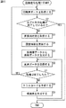
図16のフローチャートを参照して、係数種データ生成処理1について説明する。
【0258】
ステップS21において、CPU211は、学習に使われる画質パターン(例えば、パラメータs、およびzで特定される)を選択するとともに、選択した画質パターンを履歴情報に基づいて調整する。
【0259】
ステップS22において、CPU211は、全ての画質パターンに対して学習が終了したか否かを判断する。
【0260】
ステップS22において、全ての画質パターンに対して学習が終了していないと判断された場合、ステップS23において、CPU211は、既知のHD画素データをフレーム単位またはフィールド単位で取得する。
【0261】
ステップS24において、CPU211は、全てのHD画素データについて処理は終了したか否かを判断する。ステップS24において、全てのHD画素データについて処理は終了したと判断された場合、処理は、ステップS21に戻り、同様の処理が繰り返される。
【0262】
ステップS24において、全てのHD画素データについて処理は終了していないと判断された場合、ステップS25において、CPU211は、ステップS23で取得されたHD画素データより、ステップS21で調整された画質パターンに基づいて、SD画素データを生成する。
【0263】
ステップS26において、CPU211は、ステップS25で生成されたSD画素データより、ステップS23で取得された各HD画素データに対応して、クラスタップおよび予測タップの画素データを取得する。
【0264】
ステップS27において、CPU211は、生成されたSD画素データの全領域において学習処理は終了したか否かを判断する。ステップS27において、学習処理は終了したと判断された場合、処理は、ステップS23に戻り、次のHD画素データが取得され、同様の処理が繰り返される。
【0265】
ステップS27において、学習処理は終了していないと判断された場合、CPU211は、ステップS28において、ステップS26で取得されたクラスタップのSD画素データからクラスコードCLを生成し、ステップS29において、正規方程式(式(15)参照)を生成する。ステップS29の処理の終了後、処理は、ステップS26に戻り、それ以降の処理が繰り返される。
【0266】
ステップS22において、全ての画質パターンに対して学習が終了したと判断された場合、CPU211は、ステップS30において、正規方程式を掃き出し法等で解くことによって、クラスおよび出力画素(図4のHD1乃至HD4、図5のHD1′乃至HD4′参照)の各組合わせの係数種データを算出し、ステップS31において、その係数種データを、例えば、記憶部215、あるいは、ドライブ226に装着された記録媒体などに保存して、処理が終了される。
【0267】
図16を用いて説明した処理により、パーソナルコンピュータ201を用いて図10に示す係数種データ生成装置121と同様の手法によって、係数種データを得ることができる。
【0268】
また、図13の係数種データ生成装置171における処理も、同様にして、図14のパーソナルコンピュータ201を用いて、ソフトウェアで実現することが可能である。
【0269】
図17のフローチャートを参照して、係数種データ生成処理2について説明する。
【0270】
CPU211は、ステップS51において、学習に使われる画質パターン(例えば、パラメータs、およびzで特定される画質パターン)を選択するとともに、その画質パターンを履歴情報に基づいて調整し、ステップS52において、全ての画質パターンに対する係数データの算出処理が終了したか否かを判断する。
【0271】
ステップS52において、係数データの算出処理が終了していないと判断された場合、CPU211は、ステップS53において、既知のHD画素データをフレーム単位またはフィールド単位で取得し、ステップS54において、全てのHD画素データについて処理が終了したか否かを判断する。
【0272】
ステップS54において、全てのHD画素データについて処理が終了していないと判断された場合、ステップS55において、CPU211は、ステップS53において取得されたHD画素データより、ステップS51において調整された画質パターンに基づいて、SD画素データを生成する。
【0273】
CPU211は、ステップS56において、ステップS55で生成されたSD画素データより、ステップS53で取得された各HD画素データに対応して、クラスタップおよび予測タップの画素データを取得し、ステップS57において、生成されたSD画素データの全領域において学習処理は終了しているか否かを判断する。ステップS57において、学習処理は終了していると判断された場合、ステップS53に戻り、次のHD画素データを取得して、上述した処理と同様の処理が繰り返される。
【0274】
ステップS57において、学習処理は終了していないと判断された場合、CPU211は、ステップS58において、ステップS56で取得されたクラスタップのSD画素データから、クラスコードCLを生成し、ステップS59において、係数データを得るための正規方程式(式(25)参照)を生成する。ステップS59の処理の終了後、処理は、ステップS56に戻り、それ以降の処理が繰り返される。
【0275】
ステップS54において、全てのHD画素データについて処理が終了したと判断された場合、ステップS60において、CPU211は、ステップS59において生成された正規方程式を、掃き出し法などで解いて、クラスおよび出力画素(図4のHD1乃至HD4、図5のHD1′乃至HD4′参照)の各組合わせの係数データを算出し、処理は、ステップS51に戻り、次の画質パターンの選択、および調整を行って、上述した処理と同様の処理を繰り返し、次の画質パターンに対応した、各組み合わせの係数データを求める。
【0276】
ステップS52において、全ての画質パターンに対する係数データの算出処理が終了したと判断された場合、ステップS61において、CPU211は、全ての画質パターンに対する係数データから、係数種データを求めるための正規方程式(式(28)参照)を生成する。
【0277】
CPU211は、ステップS62において、ステップS61で生成された正規方程式を、掃き出し法等で解くことによって、クラスおよび出力画素の各組合わせの係数種データを算出し、ステップS63において、その係数種データを、例えば、記憶部215、あるいはドライブ226に装着されている記録媒体などに保存して、処理が終了される。
【0278】
図17を用いて説明した処理により、図14を用いて説明したパーソナルコンピュータ201において、図13に示す係数種データ生成装置171と同様の手法によって、係数種データを得ることができる。
【0279】
次に、この発明の他の実施の形態について説明する。
【0280】
図18は、図1のテレビジョン受信装置1の他の構成において、持ち運び部15に代わって用いられる持ち運び部251の構成を示すブロック図である。持ち運び部251を備えたテレビジョン受信装置1も、放送信号よりSD信号としての525i信号を得て、この525i信号をHD信号としての1050i信号に変換し、その1050i信号を出力するものである。なお、図18において、図3と対応する部分には同一の符号を付してあり、その説明は適宜省略する。
【0281】
すなわち、持ち運び部251は、情報メモリバンク51に代わって、情報メモリバンク261を有し、正規化演算部48、係数生成部52、正規化係数演算部54、および、正規化係数メモリ55が設けられていないこと以外は、図3を用いて説明した持ち運び部15と同様の構成を有している。
【0282】
情報メモリバンク261には、クラス、出力画素(図4のHD1乃至HD4、図5のHD1′乃至HD4′参照)およびパラメータs、およびzの値の組合わせ毎に、係数データWi(i=1乃至n)が予め格納されている。この係数データWiの生成方法については後述する。
【0283】
図18の持ち運び部251の動作について説明する。
【0284】
バッファメモリ14に記憶されているSD信号(525i信号)より、第2のタップ選択部42で、作成すべきHD信号(1050i信号)を構成する単位画素ブロック内の4画素(注目位置の画素)の周辺に位置する空間クラスタップのデータ(SD画素データ)が選択的に取り出される。この第2のタップ選択部42で選択的に取り出された空間クラスタップのデータ(SD画素データ)は、空間クラス検出部44に供給される。この空間クラス検出部44では、空間クラスタップのデータとしての各SD画素データに対してADRC処理が施されて、空間クラス(主に空間内の波形表現のためのクラス分類)のクラス情報としての再量子化コードqiが得られる(式(1)参照)。
【0285】
また、バッファメモリ14に記憶されているSD信号(525i信号)より、第3のタップ選択部43で、作成すべきHD信号(1050i信号)を構成する単位画素ブロック内の4画素(注目位置の画素)の周辺に位置する動きクラスタップのデータ(SD画素データ)が選択的に取り出される。この第3のタップ選択部43で選択的に取り出された動きクラスタップのデータ(SD画素データ)は、動きクラス検出部45に供給される。この動きクラス検出部45では、動きクラスタップのデータとしての各SD画素データより動きクラス(主に動きの程度を表すためのクラス分類)のクラス情報MVが得られる。
【0286】
動き情報MVと再量子化コードqiとはクラス合成部46に供給される。クラス合成部46では、供給された動き情報MVと再量子化コードqiとから、作成すべきHD信号(1050i信号)を構成する単位画素ブロック毎にその単位画素ブロック内の4画素(注目画素)が属するクラスを示すクラスコードCLが得られる(式(3)参照)。そして、このクラスコードCLは、係数メモリ53に読み出しアドレス情報として供給される。
【0287】
係数メモリ53には、例えば垂直ブランキング期間に、ユーザによって調整されたパラメータs、およびzの値に対応したクラスおよび出力画素の各組合わせの係数データWiが、システムコントローラ12の制御によって、情報メモリバンク261よりロードされて格納される。
【0288】
なお、情報メモリバンク261に、調整されたパラメータs、およびzの値に対応した係数データが蓄えられていない場合には、係数メモリ153は、その調整されたパラメータs、およびzの値の前後の値に対応した係数データWiを、情報メモリバンク261より読み出すようにし、それらを用いた補間演算処理によって、調整されたパラメータs、およびzの値に対応した係数データを得るようにしてもよい。
【0289】
上述したように、クラスコードCLが読み出しアドレス情報として係数メモリ53に供給されることで、係数メモリ53から、クラスコードCLに対応した4出力画素(奇数フィールドではHD1乃至HD4、偶数フィールドではHD1′乃至HD4′)分の推定式の係数データWiが読み出されて、推定予測演算部47に供給される。
【0290】
また、バッファメモリ14に記憶されているSD信号(525i信号)より、第1のタップ選択部41で、作成すべきHD信号(1050i信号)を構成する単位画素ブロック内の4画素(注目位置の画素)の周辺に位置する予測タップのデータ(SD画素データ)が、選択的に取り出される。
【0291】
推定予測演算部47では、予測タップのデータ(SD画素データ)xiと、係数メモリ53より読み出される4出力画素分の係数データWiとから、作成すべきHD信号を構成する単位画素ブロック内の4画素(注目位置の画素)のデータy1乃至y4が演算される(式(4)参照)。そして、推定予測演算部47より順次出力されるHD信号を構成する単位画素ブロック内の4画素のデータy1乃至y4は、後処理部49に供給される。
【0292】
後処理部49では、推定予測演算部47より順次供給される単位画素ブロック内の4画素のデータy1乃至y4が線順次化され、1050i信号のフォーマットで出力される。つまり、後処理部49からは、HD信号としての1050i信号が出力される。
【0293】
このように、持ち運び部251では、調整されたパラメータs、およびzの値に対応した推定式の係数データWi(i=1乃至n)が使用されて、HD画素データyが演算される。従って、ユーザは、パラメータs、およびzの値を調整することで、HD信号による画像の空間方向および時間方向の解像度を自由に調整することができる。
【0294】
また、履歴情報記憶部50には、システムコントローラ12から情報メモリバンク261に入力されるパラメータs、およびzの値が入力される。そして、履歴情報記憶部50の度数分布メモリ91および経時変化メモリ94(図6参照)には、システムコントローラ12の制御により、図3に示す持ち運び部15における場合と同様に、パラメータs、およびzの値の履歴情報が格納される。
【0295】
このように、履歴情報記憶部50の度数分布メモリ91、経時変化メモリ94に格納される履歴情報は、例えば、テレビジョン受信装置1のバージョンアップ時に、持ち運び部251、もしくは持ち運び部251が含まれる基板を取り換える場合において、その情報メモリバンク261に格納される係数データWiを生成する際などに利用される。
【0296】
次に、係数データWi(i=1乃至n)の生成方法について説明する。
【0297】
既に説明したように、係数種データの生成方法の他の例として、まずパラメータs、およびzの値を段階的に可変して得られるSD信号毎に、それを用いた学習によってクラスおよび出力画素の各組合わせの係数データWiを生成し、次にSD信号毎の各組合わせの係数データWiを使用して、クラスおよび出力画素の各組合わせの係数種データw10乃至wn9を求めることができる。そして、情報メモリバンク261に予め蓄えられる、クラス、出力画素およびパラメータs、およびzの値の組合わせ毎の係数データWiは、この係数種データの生成方法における、前半部分と同様の方法で生成することができる。
【0298】
図19は、係数データ生成装置271の構成を示すブロック図である。この係数データ生成装置271において、図13に示す係数種データ生成装置171と対応する部分には同一の符号を付してあり、その説明は適宜省略する。
【0299】
すなわち、図19の係数データ生成装置271は、係数種メモリ152に代わって、係数メモリ281が設けられ、正規方程式生成部183および係数種データ決定部184が設けられていないこと以外は、図13を用いて説明した係数種データ生成装置171と同様の構成を有している。
【0300】
係数メモリ281には、係数データ決定部182で決定された、パラメータs、およびzの各値に対応した、クラスおよび出力画素の各組合わせの係数データWiが記憶される。
【0301】
次に、図19に示される係数データ生成装置271の動作について説明する。
【0302】
入力端子141には、教師信号としてのHD信号(1050i信号)が供給され、このHD信号に対してSD信号生成部143で水平および垂直の間引き処理が行われて、生徒信号としてのSD信号(525i信号)が生成される。
【0303】
SD信号生成部143に入力されるパラメータs、およびzの値が順次変更されることで、HD信号からSD信号を生成する際に用いられる帯域制限フィルタの空間方向および時間方向の帯域が変更されることから、空間方向および時間方向の帯域が段階的に変化した、複数のSD信号が生成される。
【0304】
この場合、SD信号生成部143では、履歴情報が入力されるときは、この履歴情報に基づいて入力されたパラメータs、およびzの値が調整され、調整されたパラメータs、およびzの値に応じて、上述したようにHD信号からSD信号を生成する際に用いられる帯域制限フィルタの空間方向および時間方向の帯域が可変される。
【0305】
また、SD信号生成部143で生成されたSD信号(525i信号)より、第2のタップ選択部145で、HD信号(1050i信号)における注目位置の周辺に位置する空間クラスタップのデータ(SD画素データ)が選択的に取り出される。この第2のタップ選択部145で選択的に取り出された空間クラスタップのデータ(SD画素データ)は、空間クラス検出部147に供給される。空間クラス検出部147では、空間クラスタップのデータとしての各SD画素データに対してADRC処理が施されて、空間クラス(主に空間内の波形表現のためのクラス分類)のクラス情報としての再量子化コードqiが得られる(式(1)参照)。
【0306】
また、SD信号生成部143で生成されたSD信号より、第3のタップ選択部146で、HD信号に係る注目画素の周辺に位置する動きクラスタップのデータ(SD画素データ)が選択的に取り出される。この第3のタップ選択部146で選択的に取り出された動きクラスタップのデータ(SD画素データ)は、動きクラス検出部148に供給される。この動きクラス検出部148では、動きクラスタップのデータとしての各SD画素データより動きクラス(主に、動きの程度を表すためのクラス分類)のクラス情報MVが得られる。
【0307】
このクラス情報MVと上述した再量子化コードqiとは、クラス合成部149に供給される。このクラス合成部149では、これらクラス情報MVと再量子化コードqiとから、HD信号(1050i信号)における注目位置の画素データが属するクラスを示すクラスコードCLが得られる(式(3)参照)。
【0308】
また、SD信号生成部143で生成されるSD信号より、第1のタップ選択部144で、HD信号における注目位置の周辺に位置する予測タップのデータ(SD画素データ)が選択的に取り出される。
【0309】
そして、正規方程式生成部181では、入力端子141に供給されるHD信号より得られる注目位置の画素データとしての各HD画素データyと、この各HD画素データyにそれぞれ対応して第1のタップ選択部144で選択的に取り出された予測タップのデータ(SD画素データ)xiと、各HD画素データyにそれぞれ対応してクラス合成部149より出力されるクラスコードCLとから、SD信号生成部143で生成される各SD信号のそれぞれに対応して、クラスおよび出力画素の組合わせ毎に、係数データWi(i=1乃至n)を得るための正規方程式(式(25)参照)が生成される。
【0310】
そして、係数データ決定部182において、その正規方程式が解かれ、各SD信号にそれぞれ対応した、クラスおよび出力画素の各組合わせの係数データWiが求められる。すなわち、係数データ決定部182からは、クラス、出力画素およびパラメータs、およびzの値の組合わせ毎の係数データWiが得られる。この係数データWiは係数メモリ281に格納される。
【0311】
このように、図19に示される係数データ生成装置271において、図18の持ち運び部251の情報メモリバンク261に格納される、クラス、出力画素(HD1乃至HD4,HD1′乃至HD4′)およびパラメータs、およびzの値の組合わせ毎の係数データWiが生成される。
【0312】
また、この係数データ生成装置271において、SD信号生成部143では、履歴情報に基づいて、入力されるパラメータs、およびzの値が調整され、この調整されたパラメータs、およびzによって、HD信号からSD信号を得る際に用いられる帯域制限フィルタの空間方向および時間方向の帯域が可変される。従って、このようにして求められた係数データWiを、テレビジョン受信装置1のバージョンアップ時に新たに装着される、持ち運び部251、もしくは、持ち運び部251が含まれる基板の情報メモリバンク261に格納して使用することで、ユーザは、パラメータs、およびzの値の調整により、過去の解像度調整の重心位置を中心とする範囲(図11の一点鎖線枠AF参照)内で解像度の調整を行うことが可能となる。
【0313】
なお、図18の持ち運び部251では、空間方向(垂直方向および水平方向)の解像度を定めるパラメータsと時間方向(フレーム方向)の解像度を定めるパラメータzとを設定し、これらパラメータs、およびzの値を調整することで画像の空間方向および時間方向の解像度を調整し得るものとして説明したが、その他の画像の質を定めるパラメータを設けるものも、同様に構成することができる。パラメータとしては、例えば、垂直方向の解像度を定めるパラメータ、水平方向の解像度を定めるパラメータ、ノイズ除去度を定めるパラメータなど、種々のパラメータが考えられる。
【0314】
また、図18の持ち運び部251では、パラメータs、およびzの2つのパラメータを調整し得るものを示したが、1個または3個以上のパラメータを取り扱うものも、同様にして構成することができる。その場合も、履歴情報記憶部50には、それぞれのパラメータの履歴情報が格納されることとなる。そして、図19に示す係数データ生成装置271では、それぞれのパラメータの履歴情報を使用して、上述した場合と同様の生成処理を行うことができる。
【0315】
また、図18の持ち運び部251における処理を、図1の持ち運び部15における処理と同様に、例えば、図14に示されるパーソナルコンピュータ201において、ソフトウェアで実現することも可能である。この場合、ROM212等に、係数データが予め格納されて使用される。
【0316】
図20のフローチャートを参照して、図14に示されるパーソナルコンピュータ201が実行する、SD信号よりHD信号を得るための画像信号処理2について説明する。
【0317】
ステップS81において、CPU211は、SD画素データをフレーム単位またはフィールド単位で取得する。このSD画素データが入力端子222より入力される場合、SD画素データは、RAM213に一時的に格納される。また、このSD画素データが記録部215に記録されている場合、記録部215からSD画素データが読み出されて、RAM213に一時的に格納される。
【0318】
ステップS82において、CPU211は、入力SD画素データの全フレームまたは全フィールドの処理が終了しているか否かを判断する。ステップS82において、全データの処理が終了していないと判断された場合、ステップS83において、CPU211は、ユーザがリモートコマンダ203を操作して入力した画質指定値(例えばパラメータs、およびzの値など)を、例えば、RAM213より読み込むなどして取得する。
【0319】
CPU211は、ステップS84において、例えば、記録部215(図18の持ち運び部251の履歴情報記憶部50における度数分布メモリ91、経時変化メモリ94の記憶内容に相当する)に格納されている履歴情報を、取得された新たな画質指定値に基づいて更新し、ステップS85において、取得された画質指定値に基づいて、ROM212等から、その画質指定値に対応したクラスおよび出力画素(図4のHD1乃至HD4、図5のHD1′乃至HD4′参照)の各組合わせの係数データWiを読み出し、RAM213に一時的に格納する。
【0320】
CPU211は、ステップS86において、ステップS81で取得されたSD画素データより、生成すべき各HD画素データに対応して、クラスタップおよび予測タップの画素データを取得し、ステップS87において、入力されたSD画素データの全領域において、HD画素データを得る処理が終了したか否かを判断する。ステップS87において、終了していると判断された場合、処理は、ステップS81に戻り、次のフレームまたはフィールドのSD画素データに対して、同様の処理が繰り返される。
【0321】
ステップS87において、入力されたSD画素データの全領域において、HD画素データを得る処理が終了していないと判断された場合、CPU211は、ステップS88において、ステップS86において取得されたクラスタップのSD画素データからクラスコードCLを生成し、ステップS89において、そのクラスコードCLに対応した係数データと予測タップのSD画素データを使用して、推定式により、HD画素データを生成する。ステップS89の処理の終了後、処理は、ステップS86に戻り、それ以降の処理が繰り返される。
【0322】
ステップS82において、処理が終了していると判断された場合、処理が終了される。
【0323】
このように、図20を用いて説明した処理が実行されることにより、パーソナルコンピュータ201を用いて、入力されたSD信号を構成するSD画素データを処理して、HD信号を構成するHD画素データを得ることができる。上述したように、このように処理して得られたHD信号は、出力端子223から他の装置などに出力されたり、表示部221に供給されて、HD信号に対応する画像が表示されたり、更に、記録部215に供給されて、記録部215を構成するハードディスクなどに記録されたりする。
【0324】
上述したように、例えば、記録部215に格納される履歴情報は、ステップS85で使用する新たな係数データを生成する際に利用される。このように、新たに生成される係数データを利用することで、ユーザの好みに合わせた調整範囲での画質調整が可能となる。なお、上述の履歴情報は、記録部215ではなく、ドライブ226に装着された記録媒体(例えば、半導体メモリ234の一種である、メモリカードなどの装脱可能なメモリ)に格納されるようにしてもよい。
【0325】
また、図19の係数データ生成装置271における処理も、同様にして、例えば、図14に示されるパーソナルコンピュータ201によって、ソフトウェアで実現することが可能である。
【0326】
図21のフローチャートを参照して、図14のパーソナルコンピュータ201が実行する係数データ生成処理について説明する。
【0327】
CPU211は、ステップS101において、学習に使われる画質パターン(例えば、パラメータs、およびzで特定される)を選択するとともに、その画質パターンを履歴情報に基づいて調整し、ステップS102において、全ての画質パターンに対する係数データの算出処理が終了したか否かを判断する。
【0328】
ステップS102において、全ての画質パターンに対する係数データの算出処理が終了していないと判断された場合、CPU211は、ステップS103において、既知のHD画素データをフレーム単位またはフィールド単位で取得し、ステップS104において、全てのHD画素データについて処理が終了したか否かを判断する。
【0329】
ステップS104において、全てのHD画素データについて処理が終了していないと判断された場合、CPU211は、ステップS105において、ステップS103において取得されたHD画素データより、ステップS101において調整された画質パターンに基づいて、SD画素データを生成し、ステップS106において、ステップS105で生成されたSD画素データより、ステップS103で取得された各HD画素データに対応して、クラスタップおよび予測タップの画素データを取得する。
【0330】
ステップS107において、CPU211は、生成されたSD画素データの全領域において学習処理は終了しているか否かを判断する。
【0331】
ステップS107において、学習処理は終了していないと判断された場合、ステップS108において、CPU211は、ステップS106で取得されたクラスタップのSD画素データからクラスコードCLを生成し、ステップS109において、係数データを得るための正規方程式(式(25)参照)を生成する。ステップS109の処理の終了後、処理は、ステップS106に戻り、それ以降の処理が繰り返される。
【0332】
ステップS107において、学習処理は終了していると判断された場合、処理は、ステップS103に戻り、次のHD画素データを取得して、それ以降、上述した処理と同様の処理が繰り返される。
【0333】
ステップS104において、全てのHD画素データについて処理が終了したと判断された場合、ステップS110において、CPU211は、ステップS109で生成された正規方程式を、掃き出し法などで解いて、クラスおよび出力画素(図4のHD1乃至HD4、図5のHD1′乃至HD4′参照)の各組合わせの係数データを算出する。ステップS110の処理の終了後、処理は、ステップS101に戻り、次の画質パターンが選択されて調整が行われ、それ以降の処理が繰り返されて、次の画質パターンに対応した、各組合わせの係数データが求められる。
【0334】
ステップS102において、全ての画質パターンに対する係数データの算出処理が終了したと判断された場合、ステップS111において、CPU211は、全ての画質パターンに対する各クラスの係数データを、例えば、記憶部215、もしくはドライブ226に装着された記録媒体などに保存して、処理が終了される。
【0335】
このように、図21を用いて説明した処理により、図14のパーソナルコンピュータにおけるソフトウェアの処理により、図19に示す係数データ生成装置271と同様の手法によって、係数データを得ることができる。
【0336】
次に、この発明の、更に異なる他の実施の形態について説明する。
【0337】
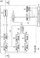
図22は、図1を用いて説明したテレビジョン受信装置1の他の実施の形態として、持ち運び部15に代わって設けられる持ち運び部301の構成を示すブロック図である。この持ち運び部301も、図3を用いて説明した持ち運び部15および図18を用いて説明した持ち運び部251と同様にして、放送信号よりSD信号としての525i信号を得て、この525i信号をHD信号としての1050i信号に変換し、その1050i信号を出力するものである。図22において、図3と対応する部分には同一の符号を付してあり、その説明は適宜省略する。
【0338】
すなわち、持ち運び部301は、情報メモリバンク51に代わって、情報メモリバンク311が備えられ、システムコントローラ12から、第1のタップ選択部41に制御信号が供給されること以外は、図3を用いて説明した持ち運び部15と同様の構成を有している。
【0339】
情報メモリバンク311には、クラスおよび出力画素(図4のHD1乃至HD4、図5のHD1′乃至HD4′参照)の組合わせ毎に、推定式(式(4)参照)で用いられる係数データWi(i=1乃至n)を生成するための生成式(式(5)参照)における係数データである係数種データw10乃至wn9が格納されている。この係数種データw10乃至wn9の生成方法については後述する。
【0340】
また、この情報メモリバンク311には、格納されている係数種データw10乃至wn9に関連して、第1のタップ選択部41で選択される予測タップのタップ位置情報が格納されている。このタップ位置情報は、係数種データw10乃至wn9を生成した際の生成装置における予測タップの位置情報である。システムコントローラ12は、このように、情報メモリバンク311に格納されているタップ位置情報に基づいて、第1のタップ選択部41で選択される予測タップの位置を、係数種データw10乃至wn9を生成した際の生成装置における予測タップの位置と等しくなるように切り換えるための制御信号を生成し、第1のタップ選択部41に供給する。
【0341】
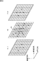
ここで、第1のタップ選択部41で選択される予測タップの位置は、水平方向、垂直方向、時間方向に亘っている。本実施の形態においては、情報メモリバンク311に格納されるタップ位置情報に基づいて、Aタイプ、Bタイプ、Cタイプのいずれかに、予測タップの位置が切り換えられる。
【0342】
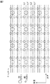
図23乃至図25は、それぞれ、Aタイプ乃至Cタイプの予測タップ位置を示す図である。ここで、「○」は選択される予測タップの位置を示している。また、F0は、作成すべきHD信号の画素データ(注目位置の画素データ)が存在するフィールドであり、このフィールドF0に中心予測タップTPが存在する。また、F−1は、フィールドF0より前のフィールドであり、F+1は、フィールドF0より後のフィールドである。
【0343】
図23に示すAタイプの予測タップ位置は、空間方向(垂直方向および水平方向)の予測タップの個数を多くしたものである。これにより、パラメータzの値で定められる時間方向の解像度に比べて、パラメータsの値で定められる空間方向の解像度が精度よく創造されるものとなる。図25に示すCタイプの予測タップ位置は、時間方向の予測タップの個数を多くしたものである。これにより、パラメータsの値で定められる空間方向の解像度に比べて、パラメータzの値で定められる時間方向の解像度が精度よく創造されるものとなる。図24に示すBタイプの予測タップ位置は、AタイプとBタイプの中間である。なお、Aタイプ乃至Cタイプのそれぞれにおいて、予測タップの個数は等しくされている。
【0344】
このように構成される持ち運び部301の動作は、図3の持ち運び部15の動作と全く同様である。すなわち、持ち運び部301は、入力されたSD信号(525i信号)をHD信号(1050i信号)に変換することができる。また、ユーザは、パラメータs、およびzの値を調整することで、HD信号による画像の空間方向および時間方向の解像度を自由に調整できる。
【0345】
また、履歴情報記憶部50の度数分布メモリ91(図6参照)には、システムコントローラ12から係数生成部52に入力されるパラメータs、およびzの値のそれぞれの度数分布の情報が格納される。また、履歴情報記憶部50の経時変化メモリ94(図6参照)には、システムコントローラ12から係数生成部52に入力されるパラメータs、およびzの値のうち、所定数、例えば10個の最新のパラメータs、およびzの値が格納される。
【0346】
このように、履歴情報記憶部50の度数分布メモリ91、経時変化メモリ94に格納される履歴情報は、例えばテレビジョン受信装置1のバージョンアップ時に持ち運び部301、もしくは持ち運び部301が含まれる基板を取り換える場合において、その情報メモリバンク311に格納される係数種データw10乃至wn9を生成する際などに利用される。
【0347】
情報メモリバンク311に格納される係数種データw10乃至wn9は、図1の持ち運び部15の情報メモリバンク51に格納される係数種データw10乃至wn9と同様の方法で生成される。
【0348】
図26は、図22の持ち運び部301の情報メモリバンク311に格納される係数種データw10乃至wn9を生成するための係数種データ生成装置321の構成を示すブロック図である。なお、図26において、図10と対応する部分には同一の符号を付してあり、その説明は適宜省略する。
【0349】
すなわち、係数種データ生成装置321は、SD信号生成部143に代わって、入力端子141に入力されるHD信号に対して水平および垂直の間引き処理を行って、生徒信号としてのSD信号を得るSD信号生成部331が設けられ、第1のタップ選択部144に代わって、履歴情報の供給を受ける第1のタップ選択部332が設けられている以外は、図10を用いて説明した、係数種データ生成装置121と同様の構成を有するものである。
【0350】
SD信号生成部331には、図22を用いて説明した持ち運び部301におけるパラメータs、およびzの値と対応した、パラメータs、およびzの値が入力される。しかし、SD信号生成部331には、図10の係数種データ生成装置121におけるSD信号生成部143とは異なり、履歴情報は入力されない。
【0351】
従って、このSD信号生成部331では、入力されたパラメータs、およびzの値が調整されることはなく、入力されたパラメータs、およびzの値そのものに応じて、HD信号からSD信号を生成する際に用いられる帯域制限フィルタの、空間方向および時間方向の帯域が可変される。
【0352】
また、第1のタップ選択部332は、SD信号生成部143より出力されるSD信号(525i信号)より、HD信号(1050i信号)における注目位置の周辺に位置する予測タップのデータ(SD画素データ)xiを選択的に取り出す。
【0353】
この第1のタップ選択部332には、図10の係数種データ生成装置121における第1のタップ選択部144とは異なり、図22を用いて説明した持ち運び部301の履歴情報記憶部50の度数分布メモリ91、経時変化メモリ94(図6参照)に格納されている、入力されたパラメータs、およびzの値の履歴情報が供給される。
【0354】
なお、使用開始前のテレビジョン受信装置1の情報メモリバンク311に格納される係数種データw10乃至wn9を生成する際には、いまだ履歴情報記憶部50の度数分布メモリ91、経時変化メモリ94に履歴情報が格納されていないので、第1のタップ選択部332に履歴情報は入力されない。つまり、第1のタップ選択部332に履歴情報が入力されるのは、例えば、テレビジョン受信装置1のバージョンアップ時に、持ち運び部301、もしくは持ち運び部301が含まれる基板を取り換える場合であって、その情報メモリバンク311に格納される係数種データw10乃至wn9を生成する際などである。
【0355】
第1のタップ選択部332では、予測タップ位置が、履歴情報に基づいて、図23乃至図25を用いて説明したAタイプ乃至Cタイプのうちのいずれかに切り換えられる。また、第1のタップ選択部332において履歴情報の入力がない場合、予測タップ位置は、図24に示されるBタイプとされる。この場合、パラメータsの値で定められる空間方向の解像度と、パラメータzの値で定められる時間方向の解像度とが、それぞれ一定の精度で創造されるように、係数種データw10乃至wn9が生成される。
【0356】
第1のタップ選択部332において、履歴情報が入力された場合、パラメータs、およびzの値のそれぞれにおける度数分布の情報が用いられて重心位置が求められる。この場合、所定数の最新のパラメータs、およびzの値に対応する値で新しいほど大きな重み付けがされる。そして、第1のタップ選択回路332では、この重心位置に応じて、予測タップ位置のタイプが選択される。
【0357】
図22を用いて説明した持ち運び部22を有するテレビジョン受信装置1では、ユーザの操作によってパラメータs、およびzの値が、例えばそれぞれ0乃至8の範囲内で、所定のステップをもって調整され、空間方向および時間方向の解像度の調整が行われる。
【0358】
上述した重心位置が、図27に示されるユーザ調整範囲において、ARaの範囲に存在し、ユーザが空間方向の解像度に重きをおいた調整を行っていると想定されるとき、予測タップ位置は、図23に示すAタイプが選択される。この場合、空間方向(垂直方向および水平方向)の予測タップの個数が多くなるため、パラメータzの値で定められる時間方向の解像度に比べて、パラメータsの値で定められる空間方向の解像度が精度よく創造されるように、係数種データw10乃至wn9が生成される。
【0359】
また、この重心位置が図27に示されるユーザ調整範囲において、ARbの範囲に存在し、ユーザが空間方向および時間方向の解像度の一方にのみ重きを置いた調整を行っているとは想定されないとき、予測タップ位置は、図24に示すBタイプが選択される。この場合、上述の履歴情報の入力がない場合と同様に、パラメータsの値で定められる空間方向の解像度と、パラメータzの値で定められる時間方向の解像度とが、それぞれ一定の精度で創造されるように、係数種データw10乃至wn9が生成される。
【0360】
更に、この重心位置が図27のARcの範囲に存在し、ユーザが空間方向の解像度に重きを置いた調整を行っていると想定されるとき、予測タップ位置は、図25に示すCタイプが選択される。例えば、テレビジョン受信装置1の持ち運び部301におけるパラメータs、およびzの調整位置が、図27に「×」印で示す位置にある場合には、重心位置はARcの範囲に存在するため、予測タップ位置は、図25に示すCタイプが選択されることとなる。
【0361】
この場合、時間方向の予測タップの個数が多くなるため、パラメータsの値で定められる空間方向の解像度に比べて、パラメータzの値で定められる時間方向の解像度が精度よく創造されるように、係数種データw10乃至wn9が生成される。
【0362】
係数種データ生成装置321のその他の構成は、図10の係数種データ生成装置121と同様である。詳細説明は省略するが、このように構成される係数種データ生成装置321の動作は、図10の係数種データ生成装置121と同様であり、図22に示す持ち運び部301の情報メモリバンク311に格納される係数種データw10乃至wn9を良好に生成することができる。なお、図22を用いて説明した持ち運び部301の情報メモリバンク311に格納されるタップ位置情報は、このように係数種データ生成装置321で係数種データw10乃至wn9を生成した際におけるタップ位置の情報である。
【0363】
このようにして求められた係数種データw10乃至wn9を、テレビジョン受信装置1のバージョンアップ時に、新たに装着される持ち運び部301、もしくは持ち運び部301が含まれる基板の情報メモリバンク311に格納して使用することで、ユーザが過去に空間方向の解像度に重きをおいている場合には空間方向の解像度が精度よく創造されるようになり、一方、ユーザが過去に時間方向の解像度に重きをおいている場合には時間方向の解像度が精度よく創造される。すなわち、新たに求められた係数種データw10乃至wn9を使用することにより、ユーザの好みに合わせた解像度創造を行うことができる。
【0364】
なお、図26に示す係数種データ生成装置321は、図10に示す係数種データ生成装置121に対応したものであったが、図13に示す係数種データ生成装置171に対応する係数種データ生成装置によっても、持ち運び部301の情報メモリバンク311に格納される係数種データw10乃至wn9を生成することができる。この場合、係数種データ生成装置171におけるSD信号生成部143および第1のタップ選択部144の部分を、図26に示す係数種データ生成装置321におけるSD信号生成部331および第1のタップ選択部332に置き換えればよい。
【0365】
また、図22の持ち運び部301では、空間方向(垂直方向および水平方向)の解像度を定めるパラメータsと時間方向(フレーム方向)の解像度を定めるパラメータzとを設定し、これらパラメータs、およびzの値を調整することで画像の空間方向および時間方向の解像度を調整し得るものを示したが、その他の2以上の方向の解像度を調整し得るものも同様に構成することができる。例えば、垂直方向および水平方向の解像度を調整するもの、あるいは垂直方向、水平方向および時間方向の解像度を調整するものにおいても、同様に構成することが可能である。
【0366】
また、図22の持ち運び部301では、第1のタップ選択部41で選択できる予測タップのタップ位置のタイプは図23乃至図25を用いて説明したタイプA乃至タイプCの3タイプであったが、選択し得るタップ位置のタイプの個数は、これに限定されるものではない。
【0367】
また、図22の持ち運び部301における処理を、例えば、図14を用いて説明したパーソナルコンピュータ201によって、ソフトウェアで実現することも可能である。この場合の画像信号処理は、基本的には、図15に示すフローチャートに沿って行われるが、ステップS6において、予測タップの画素データを取得する際に、予測タップの画素位置は、ステップS5の処理において使用された係数種データw10乃至wn9が生成された際の生成装置における予測タップの位置と等しくされる。
【0368】
また、図26の係数種データ生成装置321における処理も、同様にして、ソフトウェアで実現可能である。この場合の係数種データ生成処理は、基本的には、図16に示すフローチャートに沿って行われるが、ステップS21においては、画質パターン(パラメータs、およびzで特定される)の選択のみ行われ、履歴情報による調整は行われない。また、ステップS26において予測タップの画素データを取得する際、その予測タップの画素位置は、取得された履歴情報に基づいて選択される。
【0369】
次に、この発明の他の実施の形態について説明する。
【0370】
図28は、他の実施の形態として、図1のテレビジョン受信装置1の持ち運び部15に代わって設けられる持ち運び部341の構成を示すブロック図である。この持ち運び部341も、放送信号よりSD信号としての525i信号を得て、この525i信号をHD信号としての1050i信号に変換し、その1050i信号を出力するものである。持ち運び部15に代わって持ち運び部341が設けられたテレビジョン受信装置1は、持ち運び部15が設けられている場合と同様の動作をすることは言うまでもない。
【0371】
図28を用いて、持ち運び部341の詳細について説明する。図28において、図18と対応する部分には同一符号を付し、その詳細な説明は適宜省略する。
【0372】
すなわち、持ち運び部341は、情報メモリバンク261に代わって、情報メモリバンク351が設けられ、システムコントローラ12から、第1のタップ選択部41に制御信号が供給されている以外は、図18の持ち運び部251と基本的に同様の構成を有している。この情報メモリバンク351には、クラス、出力画素(図4のHD1乃至HD4、図5のHD1′乃至HD4′参照)およびパラメータs、およびzの値の組合わせ毎に、係数データWi(i=1乃至n)が予め格納されている。この係数データWiの生成方法については後述する。
【0373】
また、この情報メモリバンク351には、格納されている係数データWi(i=1乃至n)に関連して、第1のタップ選択部41で選択される予測タップのタップ位置情報が格納されている。このタップ位置情報は、係数データWiを生成した際の生成装置における予測タップの位置情報である。システムコントローラ12は、このように、情報メモリバンク351に格納されているタップ位置情報に基づいて、第1のタップ選択部41で選択される予測タップの位置を、係数データWiを生成した際の生成装置における予測タップの位置と等しくなるように切り換える。
【0374】
ここで、第1のタップ選択部41で選択される予測タップの位置は、水平方向、垂直方向、時間方向に亘っている。この予測タップの位置は、図22の持ち運び部301におけると同様に、情報メモリバンク351に格納されるタップ位置情報に基づいて、Aタイプ、Bタイプ、Cタイプのいずれかに切り換えられる。
【0375】
図28の持ち運び部341の動作は、図18の持ち運び部251の動作と全く同様であるので、その詳細な説明は省略する。
【0376】
すなわち、持ち運び部341は、SD信号(525i信号)をHD信号(1050i信号)に変換することができる。また、ユーザは、パラメータs、およびzの値を調整することで、HD信号による画像の空間方向および時間方向の解像度を自由に調整できる。
【0377】
また、履歴情報記憶部50の度数分布メモリ91(図6参照)には、システムコントローラ12から情報メモリバンク351に入力されるパラメータs、およびzの値のそれぞれの度数分布の情報が格納される。また、履歴情報記憶部50の経時変化メモリ94(図6参照)には、システムコントローラ12から情報メモリバンク351に入力されるパラメータs、およびzの値のうち、所定数、例えば10個の最新のパラメータs、およびzの値が格納される。
【0378】
このように、履歴情報記憶部50の度数分布メモリ91、経時変化メモリ94に格納される履歴情報は、例えば、テレビジョン受信装置1のバージョンアップ時に持ち運び部341、もしくは持ち運び部341が含まれる基板を取り換える場合において、その情報メモリバンク351に格納される係数データWiを生成する際などに利用される。
【0379】
情報メモリバンク351に格納される係数データWi(i=1乃至n)は、図18の持ち運び部251の情報メモリバンク261に格納される係数データWiと同様の方法で生成される。
【0380】
図29は、上述した持ち運び部341の情報メモリバンク351に格納される係数データWiを生成するための係数データ生成装置361の構成を示している。この図29において、図19と対応する部分には同一符号を付し、その詳細説明は省略する。
【0381】
すなわち、係数データ生成装置361は、SD信号生成部143に代わってSD信号生成部371が設けられ、第1のタップ選択部144に代わって、第1のタップ選択部372が設けられている以外は、図19の係数データ生成装置271と同様の構成を有している。
【0382】
SD信号生成部371は、入力端子141に入力されるHD信号に対して水平および垂直の間引き処理を行って、生徒信号としてのSD信号を得ることができる。SD信号生成部371には、上述した持ち運び部341におけるパラメータs、およびzの値と対応した、パラメータs、およびzの値が入力される。しかし、SD信号生成部371には、図19の係数データ生成装置271におけるSD信号生成部143とは異なり、履歴情報は入力されない。
【0383】
従って、このSD信号生成部371では、入力されたパラメータs、およびzの値が調整されることはなく、入力されたパラメータs、およびzの値そのものに応じて、HD信号からSD信号を生成する際に用いられる帯域制限フィルタの、空間方向および時間方向の帯域が可変される。
【0384】
また、係数データ生成装置361は、SD信号生成部371より出力されるSD信号(525i信号)より、HD信号(1050i信号)における注目位置の周辺に位置する予測タップのデータ(SD画素データ)xiを選択的に取り出す第1のタップ選択部372を有している。
【0385】
この第1のタップ選択部372には、図19の係数データ生成装置271における第1のタップ選択部144とは異なり、上述したテレビジョン受信装置1に搭載される持ち運び部341の履歴情報記憶部50の度数分布メモリ91、経時変化メモリ94(図6参照)に格納されている、入力されたパラメータs、およびzの値の履歴情報が供給される。
【0386】
なお、使用開始前のテレビジョン受信装置1に搭載される持ち運び部341の情報メモリバンク351に格納される係数データWiを生成する際には、いまだ履歴情報記憶部50の度数分布メモリ91、経時変化メモリ94に履歴情報が格納されていないので、第1のタップ選択部372に履歴情報は入力されない。つまり、第1のタップ選択部372に履歴情報が入力されるのは、例えばテレビジョン受信装置1のバージョンアップ時に、持ち運び部341、もしくは持ち運び部341が含まれる基板を取り換える場合であって、その情報メモリバンク351に格納される係数データWiを生成する際などである。
【0387】
第1タップ選択部372では、履歴情報に基づいて、予測タップ位置は、図23乃至図25に示すAタイプ乃至Cタイプのいずれかに切り換えられる。
【0388】
履歴情報の入力がないときは、図25に示すBタイプとされる。この場合、パラメータsの値で定められる空間方向の解像度と、パラメータzの値で定められる時間方向の解像度とが、それぞれ一定の精度で創造されるように、係数データWiが生成される。
【0389】
履歴情報が入力される場合、第1のタップ選択部372では、パラメータs、およびzの値のそれぞれにおける度数分布の情報が用いられて重心位置が求められる。この場合、所定数の最新のパラメータs、およびzの値に対応する値で新しいほど大きな重み付けがされる。そして、第1のタップ選択回路372では、この重心位置に応じて、予測タップ位置のタイプが選択される。
【0390】
持ち運び部341では、ユーザの操作によってパラメータs、およびzの値が、例えばそれぞれ0乃至8の範囲内で、所定のステップをもって調整され、空間方向および時間方向の解像度の調整が行われる。
【0391】
上述の重心位置が図27のARaの範囲に存在し、ユーザが空間方向の解像度に重きを置いた調整を行っていると想定されるときは、図23に示すAタイプが選択される。この場合、空間方向(垂直方向および水平方向)の予測タップの個数が多くなるため、パラメータzの値で定められる時間方向の解像度に比べて、パラメータsの値で定められる空間方向の解像度が精度よく創造されるように、係数データWiが生成される。
【0392】
また、この重心位置が図27のARbの範囲に存在し、ユーザが空間方向および時間方向の解像度の一方にのみ重きを置いた調整を行っているとは想定されないときは、図24に示すBタイプが選択される。この場合、上述の履歴情報の入力がない場合と同様に、パラメータsの値で定められる空間方向の解像度と、パラメータzの値で定められる時間方向の解像度とが、それぞれ一定の精度で創造されるように、係数データWiが生成される。
【0393】
更に、この重心位置が図27のARcの範囲に存在し、ユーザが空間方向の解像度に重きを置いた調整を行っていると想定されるときは、図25に示すCタイプが選択される。この場合、時間方向の予測タップの個数が多くなるため、パラメータsの値で定められる空間方向の解像度に比べて、パラメータzの値で定められる時間方向の解像度が精度よく創造されるように、係数データWiが生成される。
【0394】
係数データ生成装置361のその他の構成は、図19の係数データ生成装置271と同様である。詳細説明は省略するが、このように構成される係数データ生成装置361の動作は、図19の係数データ生成装置271と同様であり、図28に示すテレビジョン受信装置1に搭載される持ち運び部341の情報メモリバンク351に格納される係数データWiを良好に生成することができる。なお、上述した持ち運び部341の情報メモリバンク351に格納されるタップ位置情報は、このように係数データ生成装置361で係数データWiを生成した際におけるタップ位置の情報である。
【0395】
このようにして求められた係数データWiを、テレビジョン受信装置1のバージョンアップ時に新たに装着される、持ち運び部341、もしくは持ち運び部341が含まれる基板の情報メモリバンク351に格納して使用することで、ユーザが過去に空間方向の解像度に重きをおいている場合には空間方向の解像度が精度よく創造されるようになり、一方、ユーザが過去に時間方向の解像度に重きをおいている場合には時間方向の解像度が精度よく創造される。すなわち、新たに求められた係数データWiを使用することにより、ユーザの好みに合わせた解像度創造を行うことができる。
【0396】
なお、図28の持ち運び部341では、空間方向(垂直方向および水平方向)の解像度を定めるパラメータsと時間方向(フレーム方向)の解像度を定めるパラメータzとを設定し、これらパラメータs、およびzの値を調整することで画像の空間方向および時間方向の解像度を調整し得るものを示したが、その他の2以上の方向の解像度を調整し得るものも同様に構成することができる。例えば、垂直方向および水平方向の解像度を調整するもの、あるいは垂直方向、水平方向および時間方向を調整するものである。
【0397】
また、図28の持ち運び部341では、第1のタップ選択部41で選択できる予測タップのタップ位置のタイプはAタイプ乃至Cの3タイプであったが、選択し得るタップ位置のタイプの個数はこれに限定されるものではない。
【0398】
また、図28の持ち運び部341における処理を、例えば、図14に示すようなパーソナルコンピュータ201によって、ソフトウェアで実現することも可能である。この場合の画像信号処理は、基本的には、図20に示すフローチャートに沿って行われるが、ステップS86で予測タップの画素データを取得する際に、予測タップの画素位置は、ステップS85で読み出される係数データWiが生成された際の生成装置における予測タップの位置と等しくされる。
【0399】
また、同様に、図29の係数データ生成装置361における処理も、ソフトウェアで実現可能である。この場合の係数データ生成処理は、基本的には、図21に示すフローチャートに沿って行われるが、ステップS101では、画質パターン(パラメータs、およびzで特定される)の選択のみ行われ、履歴情報による調整は行われない。また、ステップS106で予測タップの画素データを取得する際、その予測タップの画素位置は履歴情報に基づいて選択される。
【0400】
なお、上述した図3、図18、図22および図28に示す持ち運び部においては、HD信号を生成する際の推定式として線形一次方程式を使用したものを例に挙げて説明したが、これに限定されるものではなく、例えば推定式として高次方程式を使用するものであってもよい。
【0401】
更に、テレビジョン受信装置1は、例えば、磁気テープ、光ディスク、磁気ディスク、光磁気ディスク、もしくは、半導体メモリなどの記録媒体にデータを記録したり、これらの記録媒体に記録されているデータを再生したりすることができる記録再生装置を備えるか、もしくは、記録再生装置と接続可能であるものとしてもよい。
【0402】
その場合、上述した図3、図18、図22および図28に示す持ち運び部を備えたテレビジョン受信装置1は、SD信号の放送データを受信して、HD信号に変換して、各種記録媒体に記録させたり、もしくは、各種記録媒体に記録されているSD信号の映像データをHD信号に変換して、再生させたり、再び各種記録媒体に記録させることができる。すなわち、本発明は、放送データに限らず、あらゆるコンテンツデータを処理する場合に適用可能である。
【0403】
また、上述した図3、図18、図22および図28に示す持ち運び部においては、SD信号(525i信号)をHD信号(1050i信号)に変換する例を示したが、この発明はそれに限定されるものでなく、推定式を使用して第1の画像信号を第2の画像信号に変換するその他の場合にも、同様に適用できることは勿論である。
【0404】
また、上述した図3、図18、図22および図28に示す持ち運び部においては、情報信号が画像信号である場合を示したが、この発明はこれに限定されない。例えば、情報信号が音声信号である場合にも、この発明を同様に適用することができる
【0405】
また、上記した図10、図13、図19、図26および図29の生成装置においては、SD信号生成回路により、教師信号としてのHD信号から生徒信号としてのSD信号を生成して、学習を行う例について説明した。しかし、HD信号とSD信号とを同時に取得できる撮像装置を利用するなどして、独立して得られたHD信号とSD信号を用いて学習を行うようにしてもよい。
【0406】
なお、上述した図3、図18、図22および図28に示す持ち運び部の履歴情報記憶部50には、それぞれのパラメータの履歴情報が格納される、すなわち、履歴情報記憶部50の度数分布メモリ91、経時変化メモリ94に履歴情報が格納され、また、情報メモリバンク51などには、係数種データw10乃至wn9が格納されるものとして説明したが、図3、図18、図22および図28を用いて説明した持ち運び部、あるいは、持ち運び部に含まれる履歴情報記憶部50、もしくは、度数分布メモリ91、経時変化メモリ94などの着脱可能に構成されている部分には、更に異なる情報が格納されるようにしてもよい。
【0407】
例えば、テレビジョン受信装置1がEPG(Electronic Program Guide)による番組表のデータを含む、デジタル放送データを受信することが可能である場合、例えば、システムコントローラ12に、受信したデジタル放送データから、EPGデータを抽出して取得させるようにすることができる。番組表のデータには、数日分の番組のそれぞれにおける情報、例えば放送日時、チャネル、タイトル、出演者の人名、ジャンル、概要などの情報が含まれている。
【0408】
システムコントローラ12は、デジタル放送データから抽出したEPGデータを基に、例えば、ユーザが視聴中、もしくは、録画中の番組のジャンルを検出し、履歴情報記憶部50、もしくは、度数分布メモリ91、経時変化メモリ94などの着脱可能に構成されている部分に格納される履歴情報や係数種データなどが、番組のジャンル毎に、区別されて格納されるように制御する。
【0409】
このことにより、持ち運び部、あるいは、履歴情報記憶部50、もしくは、度数分布メモリ91、経時変化メモリ94などの着脱可能に構成されている部分には、番組のジャンル毎に区別されて、履歴情報や係数種データなどが格納される。
【0410】
また、テレビジョン受信装置1においては、持ち運び部を含む、例えば、基板などのユニットが、装脱可能に構成されているか、もしくは、持ち運び部全体を着脱可能に構成するのではなく、履歴情報記憶部50、あるいは度数分布メモリ91、経時変化メモリ94のみが装脱可能に構成されているので、対応する部分を交換することによって、テレビジョン受信装置1の機能のバージョンアップを行うことなどが可能になっている。
【0411】
そして、この着脱可能な構成部分は、テレビジョン受信装置1のバージョンアップ以外にも利用可能である。以下、着脱可能な部分を、図3を用いて説明した持ち運び部15として、バージョンアップ以外の利用方法の具体的な例について説明する。
【0412】
例えば、映画館など、多数の視聴者が集まる場所において、持ち運び部15に格納されている履歴情報や係数種データを集計し、そのデータを基に、表示される画像の画質を、視聴者が全体的に高い満足度を得ることができる画質に調整して表示させるようにしたり、集計された多数のデータからよりよい調整値を算出し、それぞれの持ち運び部15に格納されている係数種データを更新したりすることが可能である。
【0413】
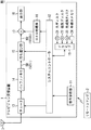
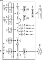
図30は、複数の持ち運び部15−1乃至持ち運び部15−nから、格納されている履歴情報や係数種データを集計し、そのデータを基に、表示される画像の画質を調整して、表示させる画像処理装置401の構成を示すブロック図である。
【0414】
画像処理装置401の構成について説明する。
【0415】
データ収集部411は、持ち運び部15−1乃至持ち運び部15−nからデータを収集し、蓄積して、演算処理部412に供給するとともに、演算処理部412から供給された、それぞれのユーザにフィードバックされる係数種データを、持ち運び部15−1乃至持ち運び部15−nに出力して、情報メモリバンク51に記録させる。
【0416】
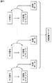
図31は、データ収集部411の、更に詳細な構成を示すブロック図である。
【0417】
データ読み出し部421−1乃至データ読み出し部421−nは、持ち運び部15−1乃至持ち運び部15−nに格納されている履歴情報や係数種データを読み出す。データ書き込み部422−1乃至データ書き込み部422−nは、データ読み出し部421−1乃至データ読み出し部421−nが読み出した履歴情報や係数種データを蓄積部423に書き込む。
【0418】
蓄積部423は、書き込まれた情報を蓄積し、所定のタイミングで、入出力インターフェース424を介して、演算処理部412に出力する。この際、蓄積部423に蓄積される情報は、例えば、持ち運び部15−1乃至15−nのそれぞれに固有に割り当てられた持ち運び部ID、もしくは、これらを所有するユーザに固有に割り当てられたユーザIDなどによって管理されるようにしてもよい。
【0419】
入出力インターフェース424は、データ収集部411と、演算処理部412とのデータの授受を行うインターフェースであり、蓄積部423で蓄積された履歴情報や係数種データを、演算処理部412に出力したり、演算処理部412から供給された、更新用の係数種データを、データ書き込み部425−1乃至データ書き込み部425−nに出力したりする。
【0420】
データ書き込み部425−1乃至データ書き込み部425−nは、入出力インターフェース424から、それぞれのユーザにフィードバックされる、例えば、更新用の係数種データなどの入力を受け、持ち運び部15−1乃至持ち運び部15−nに出力して、情報メモリバンク51に記録させる。
【0421】
データ読み出し部421−1乃至データ読み出し部421−nおよびデータ書き込み部425−1乃至データ書き込み部425−nと、持ち運び部15−1乃至持ち運び部15−nとの情報の通信は、有線によって行われるものであっても無線によって行われるものであっても、あるいは、電気的な接触によるものであっても非接触で行われるものであってもよい。
【0422】
データ読み出し部421−1乃至データ読み出し部421−nおよびデータ書き込み部425−1乃至データ書き込み部425−nは、別々に構成されていなくてもよく、例えば、図32に示されるように、映画館などにおいて、観客が使用するいす431などに、データ読み取りおよび書き込み部441として設けられ、持ち運び部15が装着可能なように構成されていてもよい。
【0423】
更に、画像処理装置401のデータ読み出し部421−1乃至データ読み出し部421−nおよびデータ書き込み部425−1乃至データ書き込み部425−nは、図33に示されるように、例えば、インターネット451などのネットワークと接続されているものとしてもよい。この場合、例えば、図14を用いて説明したパーソナルコンピュータ201と同様に、持ち運び部15が実行する処理をソフトウェアによって実行可能なパーソナルコンピュータ201−1乃至パーソナルコンピュータ201−lと、インターネット451を介して情報が授受される。また、持ち運び部15−1乃至持ち運び部15−mを、例えば、一般的なパーソナルコンピュータ452、PAD(Personal Digital(Data) Assistants)453、あるいは、携帯型電話機454などの、インターネット451と接続して通信可能な情報機器と接続させることにより、画像処理装置401と持ち運び部15−1乃至持ち運び部15−mとの通信が可能となる。
【0424】
データ収集部411は、これ以外にも、蓄積部423に蓄積されている情報を演算処理部412に出力する前に演算処理することが可能なように、もしくは、それぞれのユーザにフィードバックされる係数種データなどを、データ収集部411において算出することができるように、例えば、データを取捨選択する機能を有する選択部や、平均化などの演算を行う機能を有する演算部などを備えるようにしてもよい。また、データ収集部411が、選択部や演算部などを備える場合、蓄積部423には、選択部により選択されたデータや、演算部による演算結果を更に蓄積するようにしてもよい。
【0425】
また、データ収集部411は、持ち運び部15−1乃至15−nから、履歴情報や係数種データ以外の情報を収集して、蓄積し、演算処理部412に供給するようにしてもよい。
【0426】
再び、図30に戻り、画像処理装置401について説明する。
【0427】
演算処理部412は、データ収集部411から、履歴情報や係数種データの供給を受け、それらのデータを集計して、最も適した係数種データなどの、画像処理に利用されるパラメータを演算し、画像処理制御部413に供給するとともに、データ収集部411に供給して、持ち運び部15−1乃至持ち運び部15−nにフィードバックさせる。
【0428】
また、多くの観客、すなわち、不特定多数のユーザから収集された画像の嗜好情報である履歴情報や係数種データは、例えば、新たなテレビジョン受信機や各種画像表示装置などの画質のパラメータ設計において、好ましい画質を設計する上で非常に有効なデータである。従って、演算処理部412で演算された、新たな係数種データ、あるいは、データ収集部411で収集された履歴情報や係数種データを、外部に出力して、二次利用することができるようにしてもよい。
【0429】
図34は、演算処理部412の更に詳細な構成を示すブロック図である。
【0430】
入出力インターフェース471は、データ収集部411など、外部との情報の授受を行うインターフェースであり、データ収集部411から、履歴情報や係数種データの供給を受けたり、係数種データ生成装置121で生成された新たな係数種データを、データ収集部411、もしくは、画像処理装置401の外部の装置に出力したりする。集計演算部472は、複数の履歴情報や係数種データに対して、例えば、平均演算や、代表値算出などの統計処理を行う。係数種データ生成装置121については、図10を用いて上述しているとおりであるので、その詳細な説明は省略する。
【0431】
ここでは、画像処理に利用されるパラメータを、係数種データ生成装置121を用いて生成するものとして説明しているが、画像処理に利用されるパラメータは、他の方法を用いて生成されるようにしてもよい。
【0432】
次に、演算処理部412の処理について説明する。
【0433】
集計演算部472は、入出力インターフェース471を介して供給された、複数の履歴情報や係数種データに対して行った統計処理の結果を、係数種データ生成装置121に出力する。係数種データ生成装置121は、集計演算部472から供給された値を用いて、新たな係数種データを算出し、画像処理制御部413に出力するとともに、入出力インターフェース471を介して、データ収集部411に出力するとともに、必要に応じて、新たな画像処理装置のパラメータの作りこみのための二次利用などのために、画像処理装置401の外部の装置に出力する。
【0434】
ここでは、演算処理部412は、図10を用いて説明した係数種データ生成装置121を有し、複数の履歴情報や係数種データを用いて、新たな係数種データを生成するものとして説明したが、演算処理部412に供給される情報は、画質を決定するためのパラメータとして利用することができる情報であれば、例えば、空間解像度、時間解像度、画像のシャープネス、画面の明るさ、もしくはコントラストなど、履歴情報や係数種データ以外のものであってもかまわない。
【0435】
また、演算処理部412は、供給される情報が、例えば、履歴情報や係数種データであっても、新たな係数種データ以外の、例えば、空間解像度、時間解像度、画像のシャープネス、画面の明るさ、もしくはコントラストなどのパラメータを算出するようにしてもよい。
【0436】
すなわち、演算処理部412は、データ収集部411が、複数の持ち運び部15から収集した、例えば、履歴情報や係数種データなどの、複数のユーザの画像の嗜好をあらわす情報の入力を受け、これらの情報を基に、複数のユーザにとって、最も良好であると思われる画像を表示させるためのパラメータを算出するものである。
【0437】
再び、図30に戻り、画像処理装置401について説明する。
【0438】
画像処理制御部413は、演算処理部412から、例えば、係数種データなどの、画質を決定するためのパラメータの入力を受け、画像処理部414が実行する画像処理(例えば、空間解像度および時間解像度の設定、シャープネスの設定、画面の明るさの設定、もしくは、コントラストの設定など)を制御するための制御信号を生成し、画像処理部414に出力する。
【0439】
画像処理部414は、コンテンツデータ格納部415から、画像処理前のコンテンツデータを取得し、画像処理制御部413から供給された制御信号を基に、コンテンツデータに対して、持ち運び部15を有する複数のユーザが最も良好であると思われる画像を表示させるための画像処理(例えば、空間解像度および時間解像度の設定、シャープネスの設定、画面の明るさの設定、もしくは、コントラストの設定など)を実行する。
【0440】
コンテンツデータ格納部415は、例えば、従来の映画館で上映される画質の映画の画像データなどの、画像処理前のコンテンツデータを格納している。ここでは、コンテンツデータ格納部415は、画像処理装置401の内部に設けられているものとして説明しているが、コンテンツデータ格納部415は、画像処理装置401の外部に設けられていてもよいし、コンテンツデータ格納部415を設けることなく、画像処理部414が、ネットワークなどの通信手段を介して、コンテンツデータを取得することができるようにしてもよい。
【0441】
表示制御部416は、画像処理部414から供給された、画像処理済の画像データの、図示しないスクリーンなどへの表示を制御する。
【0442】
また、ユーザの画像の嗜好は、例えば、そのコンテンツのカテゴリによって偏りがあると考えられる。例えば、ラブストーリであれば、コントラストやシャープネスの低い、淡い印象の画像が好適であると考えるユーザが、アクション映画に対しては、コントラストやシャープネスが高く、はっきりとした印象を持つ画像が好適であると考える場合などが考えられる。
【0443】
そこで、上述したように、持ち運び部15−1乃至持ち運び部15−nに記録されている、例えば、履歴情報や係数種データなどの、複数のユーザの画像の嗜好をあらわす情報が、EPGなどを基に、そのコンテンツのカテゴリによって区別されているような場合、画像処理部401は、画像処理部414によって処理されるコンテンツのカテゴリに対応した嗜好情報を、持ち運び部15−1乃至持ち運び部15−nから取得し、それらの情報を用いて、画像処理を行うようにする。このことにより、ユーザの嗜好により合致した画像を生成することができる。
【0444】
また、例えば、多くの映画上映施設を有する、いわゆるシネマコンプレックスなどにおいて、同一の映画が複数の会場で上映される場合、それぞれの会場において上映される映画の画質を、予め異なるものとし、持ち運び部15に記録されているそれぞれのユーザの嗜好情報に基づいて、対応するユーザの嗜好に最も合致した画質で上映される会場を案内することができるようにしてもよい。
【0445】
図35は、上映会場案内装置501の外観を示す図である。上映会場案内装置501は、例えば、シネマコンプレックスの入り口などに設置されている。
【0446】
ユーザは、上映会場案内装置501の持ち運び部挿入部512に持ち運び部15を挿入する。図35においては、持ち運び部15を、上映会場案内装置501に挿入するものとして図示したが、上映会場案内装置501は、持ち運び部15と非接触で通信可能であるようにしてもよい。
【0447】
上映会場案内装置501は、持ち運び部15に格納されている、例えば、履歴情報や係数種データなどの、持ち運び部15を保有するユーザの画像の嗜好をあらわす情報を読み出して、複数の上映会場のうち、対応するユーザの画像の嗜好に最も合致した上映会場を判定し、判定結果を表示部511に表示する。
【0448】
図36は、上映会場案内装置501の構成を示すブロック図である。
【0449】
データ読み出し部521は、持ち運び部挿入部512に挿入された持ち運び部15に格納されている、例えば、履歴情報や係数種データなどの、ユーザの画像の嗜好をあらわす情報を読み出す。データ書き込み部522は、データ読み出し部521によって読み出されたユーザの画像の嗜好を表す情報を蓄積部523に書き込む。蓄積部523は、書き込まれた情報を蓄積し、必要に応じて、入出力インターフェース524を介して、蓄積された嗜好情報を、外部の装置に出力する。ここでも、多くの観客から収集された履歴情報や係数種データは、例えば、新たなテレビジョン受信機や各種画像表示装置などの画質のパラメータ設計において非常に有効なデータであるので、これらの目的のために、二次利用することができる。
【0450】
また、入出力インターフェース524は、必要に応じて、持ち運び部挿入部512に挿入されている持ち運び部15に記録されている係数種データなどを更新するための情報の入力を受け、データ書き込み部525に出力する。データ書き込み部525は、入力された情報を、持ち運び部挿入部512に挿入されている持ち運び部15に出力し、情報メモリバンク51に格納されている係数種データなどを更新させる。
【0451】
データ読み出し部521は、更に、読み出したユーザの画像の嗜好情報を判定部526に供給する。上映会場データ格納部528は、入出力インターフェース524を介して、上映会場毎の、上映される画像の特徴量に関する情報(例えば、空間解像度および時間解像度の設定、シャープネスの設定、画面の明るさの設定、もしくは、コントラストの設定など)の入力を受け、格納する。判定部526は、上映会場データ格納部528に格納されている、上映会場毎の、上映される画像の特徴量に関する情報を参照し、データ読み出し部521から供給されたユーザの画像の嗜好情報に最も合致する上映会場を判定し、判定結果を表示制御部527に出力する。
【0452】
表示制御部527は、判定部526から供給された判定結果を基に、例えば、「スクリーン3に御入場下さい」などの、ユーザに上映会場を通知するために表示部511に表示させるテキスト、あるいは画像データを生成し、表示部511に表示させる。
【0453】
ここでは、判定部526から供給された判定結果を基に、例えば、「スクリーン3に御入場下さい」などの、ユーザに上映会場を通知するためのメッセージを表示部511に表示させるものとして説明したが、ユーザに上映会場を通知するためのメッセージを、例えば、音声として出力したり、紙媒体などに印刷して出力したりしてもよい。また、例えば、携帯型電話機などの、ユーザが保有する情報処理装置などに、判定部526から供給された判定結果を送信して表示させるようにしてもよい。
【0454】
ここでも、持ち運び部15に記録されている、例えば、履歴情報や係数種データなどの、複数のユーザの画像の嗜好をあらわす情報が、EPGなどを基に、そのコンテンツのカテゴリによって区別されているような場合、判定部526は、上映されるコンテンツのカテゴリに対応した嗜好情報を基に、ユーザの画像の嗜好情報に最も合致する上映会場を判定するようにすることができる。
【0455】
このような処理により、それぞれのユーザの画像の嗜好にできるだけ合致するような画像処理が施されたコンテンツをユーザに提供することができるのみならず、新たなテレビジョン受信機や各種画像表示装置などの画質のパラメータ設計において非常に有効なデータを効率よく収集することができる。
【0456】
なお、図35および図36においては、持ち運び部15が、上映会場案内装置501の持ち運び部挿入部512に挿入されるものとして説明したが、持ち運び部15と上映会場案内装置501とは、例えば、インターネットなどのネットワークを介して、情報の授受が可能なようにしてもよい。この場合、上映会場案内装置501には、持ち運び部挿入部512に代わって、インターネットなどのネットワークを介した通信が可能な、図示しない通信処理部などが備えられる。
【0457】
この場合、ユーザは、持ち運び部15に予め記録されている、例えば、履歴情報や係数種データなどの、ユーザの画像の嗜好をあらわす情報を、ユーザIDなどとともに、インターネットを介して、上映会場案内装置501に送信する。上映会場案内装置501は、供給されたユーザの画像の嗜好を表す情報を基に、対応するユーザの嗜好に合致した上映会場を判定する。そして、上映会場案内装置501は、上映会場の判定結果を、即時にインターネットを介してユーザに対して通知するようにしてもよいし、上映会場の判定結果をユーザIDに対応つけて一時保存しておき、ユーザがシネマコンプレックスなどの上映会場に来場した際に、ユーザIDの入力を受けて、表示部511に表示させるようにしてもよい。
【0458】
また、持ち運び部15と上映会場案内装置501とで、例えば、インターネットなどを介して、情報の授受が行われる場合においては、入出力インターフェース524から入力された、係数種データなどを更新するための情報は、データ書き込み部525によって、インターネットを介して持ち運び部15に出力され、情報メモリバンク51に格納されている係数種データなどが更新される。
【0459】
図30乃至図36を用いて説明した処理においては、ユーザが多数集まる場所として、映画館を想定し、提供されるコンテンツを映画であるものとして説明したが、本発明は、映画館における使用のみに限定されるものではなく、例えば、テーマパークなど、ユーザが多く集まるあらゆる場所や、インターネットを介したコンテンツデータの配信など、ユーザの嗜好情報が効率よく集められる手段において適用することが可能である。
【0460】
以上説明したように、ユーザが画質調整を行うことにより蓄積されたユーザの画像の嗜好情報を記録している部分を含む、例えば、図3を用いて説明した持ち運び部15などを、テレビジョン受信装置1から取り外して持ち運び可能にすることにより、ユーザの画質の嗜好情報を利用することができる。
【0461】
ユーザの画質の嗜好情報は、テレビジョン受信装置1のバージョンアップにおいて利用されるのみならず、例えば、映画館など、多数の視聴者が集まる場所において、持ち運び部15などに格納されている履歴情報や係数種データを集計し、そのデータを基に、表示される画像の画質を、視聴者が全体的に高い満足度を得ることができる画質に調整して表示させるようにしたり、集計された多数のデータからよりよい調整値を算出し、それぞれの持ち運び部15に格納されている係数種データを更新したりすることが可能である。
【0462】
また、例えば、多くの映画上映施設を有する、いわゆるシネマコンプレックスなどにおいて、同一の映画が複数の会場で上映される場合、それぞれの会場において上映される映画の画質を、予め異なるものとし、持ち運び部15などに記録されているそれぞれのユーザの嗜好情報に基づいて、対応するユーザの嗜好に最も合致した画質で上映される会場を案内することが可能である。
【0463】
また、ユーザの画質の嗜好情報は、新たなテレビジョン受信機や各種画像表示装置などの画質のパラメータ設計において非常に有効なデータであり、ユーザが多数集まる、例えば、映画館やテーマパークなどにおいて本発明を適用すること、もしくは、インターネットを介する情報通信など、不特定多数のユーザと情報の授受が可能な場合に本発明を適用することなどにより、効率よく収集することができる。
【0464】
上述した一連の処理は、ソフトウェアにより実行することもできる。そのソフトウェアは、そのソフトウェアを構成するプログラムが、専用のハードウェアに組み込まれているコンピュータ、または、各種のプログラムをインストールすることで、各種の機能を実行することが可能な、例えば汎用のパーソナルコンピュータなどに、記録媒体からインストールされる。
【0465】
この記録媒体は、図1、もしくは、図14に示すように、コンピュータとは別に、ユーザにプログラムを提供するために配布される、プログラムが記録されている磁気ディスク21、もしくは231(フレキシブルディスクを含む)、光ディスク22、もしくは232(CD-ROM(Compact Disk-Read Only Memory),DVD(Digital Versatile Disk)を含む)、光磁気ディスク23、もしくは233(MD(Mini-Disk)(商標)を含む)、あるいは、半導体メモリ24、もしくは234などよりなるパッケージメディアなどにより構成される。
【0466】
また、本明細書において、記録媒体に記録されるプログラムを記述するステップは、記載された順序に沿って時系列的に行われる処理はもちろん、必ずしも時系列的に処理されなくとも、並列的あるいは個別に実行される処理をも含むものである。
【0467】
【発明の効果】
第1の本発明によれば、コンテンツデータを処理することができる。
また、第1の本発明によれば、複数のユーザに対して提供されるコンテンツデータを、複数のユーザが有する情報処理装置に記憶されている付加情報を基に処理することができる。
【0468】
第2の本発明によれば、ユーザの嗜好に合致したコンテンツの表示場所をユーザに案内することができる。
また、第2の本発明によれば、複数のユーザが有する情報処理装置に記憶されている付加情報を基に、ユーザの嗜好に合致したコンテンツの表示場所を表示させることができる。
【図面の簡単な説明】
【図1】テレビジョン受信装置の構成を示すブロック図である。
【図2】525i信号と1050i信号の画素位置関係を示す図である。
【図3】図1の持ち運び部15の構成を示すブロック図である。
【図4】HD信号(1050i信号)の単位画素ブロック内の4画素の中心予測タップからの位相ずれ(奇数フィールド)を示す図である。
【図5】HD信号(1050i信号)の単位画素ブロック内の4画素の中心予測タップからの位相ずれ(偶数フィールド)を示す図である。
【図6】履歴情報記憶部の構成を示すブロック図である。
【図7】画質を調整するためのユーザインターフェース例を示す図である。
【図8】図7の調整画面を拡大して示した図である。
【図9】係数種データの生成方法の一例を示す図である。
【図10】係数種データ生成装置の構成例を示すブロック図である。
【図11】解像度調整範囲の変化を説明するための図である。
【図12】係数種データの生成方法の他の例を示す図である。
【図13】係数種データ生成装置の他の構成例を示すブロック図である。
【図14】パーソナルコンピュータの構成を示すブロック図である。
【図15】画像信号処理1について説明するフローチャートである。
【図16】係数種データ生成処理1について説明するフローチャートである。
【図17】係数種データ生成処理2について説明するフローチャートである。
【図18】他の実施の形態としての持ち運び部の構成を示すブロック図である。
【図19】係数データ生成装置の構成例を示すブロック図である。
【図20】画像信号処理2について説明するフローチャートである。
【図21】係数データ生成処理について説明するフローチャートである。
【図22】更に他の実施の形態としての持ち運び部の構成を示すブロック図である。
【図23】予測タップの変更を説明するための図である。
【図24】予測タップの変更を説明するための図である。
【図25】予測タップの変更を説明するための図である。
【図26】他の実施の形態としての係数種データ生成装置の構成を示すブロック図である。
【図27】ユーザ調整範囲について説明するための図である。
【図28】更に他の実施の形態としての持ち運び部の構成を示すブロック図である。
【図29】他の実施の形態としての係数データ生成装置の構成を示すブロック図である。
【図30】画像処理装置の構成を示すブロック図である。
【図31】図30のデータ収集部の構成を示すブロック図である。
【図32】データ収集方法の例について説明する図である。
【図33】データ収集方法の例について説明する図である。
【図34】図30の演算処理部の構成を示すブロック図である。
【図35】上映会場案内装置の外観構成図である。
【図36】図35の上映会場案内装置の構成を示すブロック図である。
【符号の説明】
1 テレビジョン受信装置, 12 システムコントローラ, 15 持ち運び部, 41 第1のタップ選択部, 42 第2のタップ選択部, 43 第3のタップ選択部, 44 空間クラス検出部, 45 動きクラス検出部, 46 クラス合成部, 47 推定予測演算部, 48 正規化演算部, 49後処理部, 50 履歴情報記憶部 51 情報メモリバンク, 52 係数生成部, 53 係数メモリ, 54 正規化係数演算部, 55 正規化係数メモリ, 91 度数分布メモリ, 92 カウンタ, 93 平均化部, 94 経時変化メモリ, 121 係数種データ生成装置, 141,142 入力端子, 143 SD信号生成部, 144 第1のタップ選択部, 145第2のタップ選択部, 146 第3のタップ選択部, 147 空間クラス検出部, 148 動きクラス検出部, 149 クラス合成部, 150 正規方程式生成部, 151 係数種データ決定部, 152 係数種メモリ, 401 画像処理装置, 411 データ収集部, 412 演算処理部, 413 画像処理制御部, 414 画像処理部, 145 コンテンツデータ格納部, 416 表示制御部, 423 蓄積部, 451 インターネット,472 集計演算部, 501 上映会場案内装置, 523 蓄積部, 526 判定部, 527 表示制御部[0001]
BACKGROUND OF THE INVENTION
The present invention relates to an information processing device, an information processing method, a recording medium, and a program, and is particularly suitable for performing image processing using preference information for image quality of a plurality of users or collecting preference information. The present invention relates to an information processing apparatus and information processing method, a recording medium, and a program.
[0002]
[Prior art]
In recent years, the development of television receivers capable of obtaining higher-resolution images has been desired due to the increase in audio / visual orientation, and so-called high-vision has been developed in response to this demand. The number of high-definition scanning lines is 1125, which is more than twice the number of NTSC scanning lines, which is 525. The aspect ratio of the high-definition television is 9:16, whereas the aspect ratio of the NTSC system is 3: 4. For this reason, high-definition images can be displayed with a higher resolution and presence than in the NTSC system.
[0003]
Hi-Vision has such excellent characteristics, but even if an NTSC video signal is supplied as it is, image display by Hi-Vision cannot be performed. This is because the standards differ between the NTSC system and the high-definition as described above.
[0004]
Therefore, the present applicant has previously proposed a conversion device for converting an NTSC video signal into a high-definition video signal in order to display an image corresponding to the NTSC video signal in a high-definition method. No. 8-51599). In this conversion apparatus, pixel data of a block (area) corresponding to pixel data at a target position of a high-definition video signal is extracted from an NTSC video signal, and the above-described conversion is performed based on the level distribution pattern of the pixel data of this block. The class to which the pixel data of the target position belongs is determined, and the pixel data of the target position is generated corresponding to this class.
[0005]
[Problems to be solved by the invention]
However, in the above-described conversion device, the resolution of the image by the high-definition video signal is fixed, and the resolution can be set to the user's preference according to the image content, etc., as in the conventional adjustment of contrast and sharpness. could not.
[0006]
Therefore, the present applicant further generates a high-definition video signal corresponding to the input parameter value when converting the NTSC video signal to a high-definition video signal, and obtains the high-definition video signal. The thing which the user can adjust the resolution of an image freely was proposed (Japanese Patent Laid-Open No. 2001-238185).
[0007]
In this case, the user can freely adjust the resolution of the image, but the adjustment range is fixed. For example, a sufficient adjustment range is secured for a user who performs adjustment around one end of the adjustment range. I can't say. In other words, it is desirable to be able to make adjustments according to user preferences.
[0008]
In addition, when developing a new television receiver or upgrading the television receiver, in order to create the image quality of the image displayed by the television receiver, it matches the user's preference as described above. The adjustment value data is very effective data, and by collecting the adjustment value data of many users, it is possible to create an image quality preferable for the majority of users.
[0009]
However, it has been very difficult to collect image quality adjustment value data of an unspecified number of users. For example, collecting preference information of an unspecified number of users through a questionnaire or the like is not realistic because it requires enormous costs and time.
[0010]
In addition, an unspecified number of users appreciate the same image. For example, in a movie theater or the like, there is no technology that reflects the preference of each user's image. There was no choice but to watch at.
[0011]
The present invention has been made in view of such a situation, and collects image quality preferences of an unspecified number of users, and uses them to reflect the preferences of individual users in, for example, movie theaters. It is possible to provide a selected image and collect preference information of an unspecified number of users.
[0012]
[Means for Solving the Problems]
The first information processing apparatus of the present invention relates to processing means for processing the first content data, collection means for collecting additional information for controlling the processing means, and additional information collected by the collection means. Storage means for storing the information to be processed, and control means for controlling the processing means based on information related to the additional information stored by the storage means, and the collecting means is another information processing possessed by a plurality of users. The first content data collected by the additional information stored in the apparatus and processed by the processing means is content data provided to a plurality of users.
[0013]
An arithmetic processing means for arithmetically processing information related to the additional information stored by the storage means can be further provided, and the control means includes information related to the additional information arithmetically processed by the arithmetic processing means. Based on this, the processing means can be controlled.
[0014]
The storage means can further store the result of the arithmetic processing by the arithmetic processing means.
[0015]
A display control means for controlling the display of the first content data processed by the processing means can be further provided.
[0016]
The additional information can include information related to image quality preferences of the second content data viewed by the user in the past.
[0017]
The additional information can further include the category information of the second content data referred to by the user when the information related to the preference is collected, and the control means includes storage means. The processing means can be controlled based on the additional information that matches the category of the first content data provided to a plurality of users among the information related to the additional information stored in the above.
[0023]
The additional information stored in other information processing apparatuses owned by a plurality of users relates to the adjustment value of the image quality adjustment performed by the user with respect to the image quality of the second content data viewed by each user in the past. Information can be included.
[0024]
It is possible to further include output means for outputting the result of the arithmetic processing by the arithmetic processing means to other information processing apparatuses owned by a plurality of users.
[0025]
It is possible to attach another information processing apparatus owned by a plurality of users and to further include a mounting means for exchanging information with the other information processing apparatus. The collection means is mounted on the mounting means. Additional information stored in another information processing apparatus can be collected.
[0026]
Computation processing means for computing information related to the additional information stored by the storage means, and output means for outputting computation processing results by the computation processing means to other information processing apparatuses owned by a plurality of users, respectively. The output means can cause the other information processing apparatus attached to the attachment means to output the result of the arithmetic processing by the arithmetic processing means.
[0027]
An information exchanging means for exchanging information via a predetermined network can be further provided, and the collecting means is stored in another information processing apparatus via the predetermined network by the information exchanging means. Additional information can be collected.
[0028]
Computation processing means for computing information related to the additional information stored by the storage means, and output means for outputting computation processing results by the computation processing means to other information processing apparatuses owned by a plurality of users, respectively. The output means can cause the other information processing apparatus to output the result of the arithmetic processing by the arithmetic processing means via the predetermined network by the information transfer means.
[0030]
The first information processing method of the present invention includes a processing step for processing content data, a collecting step for collecting additional information for controlling processing of the processing step, and additional information collected by processing of the collecting step. A storage control step for controlling storage of related information; and a control step for controlling processing of the processing step based on information related to additional information whose storage is controlled by processing of the storage control step. In the processing, additional information stored in other information processing apparatuses held by a plurality of users is collected, and the content data processed by the processing step processing is content data provided to the plurality of users. Features.
[0031]
The program recorded on the first recording medium of the present invention is collected by a processing step for processing content data, a collecting step for collecting additional information for controlling the processing of the processing step, and a processing of the collecting step A storage control step that controls storage of information related to the additional information, and a control step that controls processing of the processing step based on information related to additional information whose storage is controlled by processing of the storage control step. In addition, in the process of the collecting step, additional data stored in other information processing apparatuses held by a plurality of users is collected, and the content data processed by the processing of the processing step is content provided to the plurality of users. It is characterized by being data.
[0032]
The first program of the present invention relates to a processing step for processing content data, a collecting step for collecting additional information for controlling the processing of the processing step, and additional information collected by the processing of the collecting step. A storage control step for controlling storage of information, and a control step for controlling the processing of the processing step based on information related to the additional information whose storage is controlled by the processing of the storage control step. Collecting additional information stored in other information processing apparatuses owned by a plurality of users, and the content data processed by the processing step is content data provided to a plurality of users To do.
[0033]
The second information processing apparatus according to the present invention includes a first storage unit that stores information on each display location of the same first content data displayed with a plurality of image quality, and other information held by a plurality of users. Collecting means for collecting additional information stored in the information processing apparatus, information on the display location stored by the first storing means, and display with a plurality of image quality based on the additional information collected by the collecting means Determination means for determining a display location where the first content data is displayed with an image quality that matches the preference of the corresponding user among the first content data to be displayed, and display means for displaying a determination result by the determination means The additional information includes information related to image quality preference of content data viewed by the user.
[0034]
Second storage means for storing additional information collected by the collecting means can be further provided.
[0035]
The additional information can further include the category information of the second content data referred to by the user when the information related to the preference is collected. Based on the additional information that matches the category of the first content data among the collected additional information, the display location where the first content data is displayed with the image quality that matches the preference of the corresponding user is determined. can do.
[0041]
The additional information stored in other information processing apparatuses owned by a plurality of users includes an adjustment value of image quality adjustment performed by the user with respect to the display image quality of the second content data referred to by each user in the past. Information can be included.
[0042]
An acquisition unit that acquires information for updating additional information stored in another information processing device held by the user, and an output that outputs the information acquired by the acquisition unit to another information processing device held by the user Means can be further provided.
[0043]
The information processing apparatus can be further equipped with a mounting means for sending and receiving information by mounting another information processing apparatus held by the user, and the collection means is stored in the other information processing apparatus mounted on the mounting means. Additional information can be collected.
[0044]
An acquisition unit that acquires information for updating additional information stored in another information processing device held by the user, and an output that outputs the information acquired by the acquisition unit to another information processing device held by the user And the output means can cause the other information processing apparatus attached to the attachment means to output the information acquired by the acquisition means.
[0045]
An information exchanging means for exchanging information via a predetermined network can be further provided, and the collecting means is stored in another information processing apparatus via the predetermined network by the information exchanging means. Additional information can be collected.
[0046]
An acquisition unit that acquires information for updating additional information stored in another information processing device held by the user, and an output that outputs the information acquired by the acquisition unit to another information processing device held by the user And the output means causes the information exchange means to output the information acquired by the acquisition means to another information processing apparatus via a predetermined network. Can do.
[0048]
The second information processing method of the present invention includes a storage control step for controlling storage of information relating to each display location of the same content data displayed with a plurality of image quality, and another information processing apparatus possessed by a plurality of users. A plurality of image quality based on the collection step for collecting the additional information stored in the memory, the information on the display location whose storage is controlled by the processing of the storage control step, and the additional information collected by the processing of the collection step. A determination step of determining a display location where the content data is displayed with an image quality that matches the preference of the corresponding user among the displayed content data;
And a display step for displaying a determination result obtained by the determination step. The additional information includes information related to a preference of image quality of content data viewed by the user.
[0049]
The program recorded on the second recording medium of the present invention includes a storage control step for controlling storage of information related to each display location of the same content data displayed with a plurality of image quality, Based on the collection step for collecting the additional information stored in the information processing apparatus, the information on the display location whose storage is controlled by the process of the storage control step, and the additional information collected by the process of the collection step, A determination step for determining a display location where the content data is displayed with an image quality that matches the preference of the corresponding user among the content data displayed with a plurality of image quality, and a display step for displaying a determination result by the processing of the determination step; The additional information includes information related to image quality preference of content data viewed by the user. To.
[0050]
A second program according to the present invention stores a storage control step for controlling storage of information related to each display location of the same content data displayed with a plurality of image quality, and stores the information in another information processing apparatus owned by a plurality of users A collection step that collects additional information that is stored, information about a display location whose storage is controlled by the processing of the storage control step, and additional information collected by the processing of the collection step. Content information including a determination step for determining a display location where the content data is displayed with an image quality that matches a corresponding user's preference, and a display step for displaying a determination result by the processing of the determination step. In addition, the content data includes information related to image quality preferences of content data viewed by the user.
[0051]
In the first information processing apparatus, information processing method, and program of the present invention, content data is processed, additional information for controlling the processing of the content data is collected, and information related to the collected additional information is stored. Based on the information stored and related to the additional information, the processing of the content data is controlled, the additional information stored in the other information processing devices held by a plurality of users is collected, and the processed content data is Content data provided to a plurality of users.
[0052]
In the second information processing apparatus, the information processing method, and the program of the present invention, information about each display location of the same first content data displayed with a plurality of image quality is stored and held by a plurality of users. Additional information stored in another information processing apparatus is collected and based on the information about the display location and the additional information, the first content data displayed in multiple image quality matches the corresponding user's preference. The display location where the first content data is displayed with the image quality is determined, the determination result is displayed, and the additional information includes information regarding the image quality preference of the content data viewed by the user.
[0053]
DETAILED DESCRIPTION OF THE INVENTION
Hereinafter, embodiments of the present invention will be described with reference to the drawings.
[0054]
FIG. 1 is a block diagram showing the configuration of the
[0055]
FIG. 2 shows the pixel position relationship of a frame (F) in which a 525i signal and a 1050i signal are present. The pixel position of an odd (o) field is indicated by a solid line, and the pixel position of an even (e) field is indicated by a broken line. ing. Large dots are pixels of 525i signal, and small dots are pixels of 1050i signal. As can be seen from FIG. 2, the pixel data of the 1050i signal includes line data L1 and L1 ′ at positions close to the line of the 525i signal and line data L2 and L2 ′ at positions far from the line of the 525i signal. Here, L1 and L2 are line data of odd fields, and L1 'and L2' are line data of even fields. The number of pixels in each line of the 1050i signal is twice the number of pixels in each line of the 525i signal.
[0056]
Returning to FIG. 1, the configuration of the
[0057]
The receiving antenna 3 receives a broadcast signal (RF modulated signal). The
[0058]
The carrying
[0059]
FIG. 3 is a block diagram showing a more detailed configuration of the carrying
[0060]
The first
[0061]
The first
[0062]
The space
[0063]
In the space
[0064]
Originally, ADRC is an adaptive requantization method developed for high-performance coding for VTR (Video Tape Recorder), but it can efficiently express a local pattern of signal level with a short word length. It is suitable for use in data compression. When ADRC is used, the maximum value of space class tap data (SD pixel data) is MAX, the minimum value is MIN, the dynamic range of space class tap data is DR (= MAX−MIN + 1), and the number of requantization bits Is P, the requantized code qi as compressed data is obtained by the calculation of the equation (1) for each SD pixel data ki as the space class tap data. However, in the formula (1), [] means a truncation process. When there are Na SD pixel data as space class tap data, i = 1 to Na.
[0065]
[Expression 1]
![]()
![]()
The motion
[0067]
In this motion
[0068]
[Expression 2]
![]()
Then, in the motion
[0070]
The
[0071]
In the
[0072]
[Equation 3]
![]()
The
[0074]
The carrying
[0075]
Here, the n pixel data positions of the prediction tap selectively extracted by the
[0076]
[Expression 4]
![]()
Then, coefficient data Wi (i = 1 to n) of the estimation formula is generated by a generation formula including parameters s and z as shown in formula (5). The
[0078]
[Equation 5]
![]()
As described above, when the 525i signal is converted into the 1050i signal, it is necessary to obtain four pixels of the 1050i signal corresponding to one pixel of the 525i signal in each of the odd and even fields. In this case, the four pixels in the 2 × 2 unit pixel block constituting the 1050i signal in each of the odd and even fields have different phase shifts with respect to the central prediction tap.
[0080]
FIG. 4 shows center prediction taps SD in four pixels HD1 to HD4 in a 2 × 2 unit pixel block constituting a 1050i signal in an odd field. 0 The phase shift from is shown. Here, the positions of HD1 to HD4 are respectively SD. 0 Are shifted by k1 to k4 in the horizontal direction and m1 to m4 in the vertical direction.
[0081]
FIG. 5 shows the center prediction tap SD in the four pixels HD1 'to HD4' in the 2 &2; unit pixel block constituting the 1050i signal in the even field. 0 The phase shift from ′ is shown. Here, the positions of HD1 'to HD4' are respectively SD. 0 Is shifted from the position of ′ by k1 ′ to k4 ′ in the horizontal direction and by m1 ′ to m4 ′ in the vertical direction.
[0082]
Accordingly, the
[0083]
The
[0084]
The coefficient data Wi (i = 1 to n) of each class generated by the
[0085]
The normalization
[0086]
[Formula 6]
![]()
The estimated
[0088]
As described above, when an SD signal (525i signal) is converted to an HD signal (1050i signal), four pixels of the HD signal (HD1 to HD4 in FIG. 4 and HD1 in FIG. Therefore, the estimated
[0089]
The
[0090]
The
[0091]
The history
[0092]
FIG. 6 is a block diagram showing a more detailed configuration of the history
[0093]
For this purpose, the history
[0094]
The
[0095]
The averaging
[0096]
In this case, when the number of times of input is M, that is, when the count value of the
[0097]
[Expression 7]
![]()
![]()
[Equation 8]
![]()
![]()
Thus, overflow is prevented by using the average value of the frequencies of the parameters s and z as the frequency distribution information of the parameters s and z stored in the
[0100]
In addition, instead of using the average value of the frequencies at the values of the parameters s and z, even if the value obtained by normalizing the frequencies at the values of the parameters s and z with the maximum frequency is used, overflow similarly occurs. Can be prevented.
[0101]
The history
[0102]
The writing operation to the time-varying
[0103]
In the
[0104]
Note that the entire carrying
[0105]
Returning to FIG. 1, the configuration of the
[0106]
An OSD (On Screen Display) processing unit 16 generates a display signal SCH for displaying a character figure on the screen of the
[0107]
In addition, a
[0108]
The operation of the
[0109]
The
[0110]
The SD signal (525i signal) output from the
[0111]
That is, the carrying
[0112]
Further, the user can adjust the spatial and temporal resolutions of the image displayed on the screen of the
[0113]
FIG. 7 shows an example of a user interface for adjusting the parameters s and z. At the time of adjustment, an
[0114]
The user can move the position of the
[0115]
FIG. 8 shows an enlarged portion of the
[0116]
Note that the
[0117]
Next, the operation of the carrying
[0118]
The second
[0119]
In addition, the third
[0120]
The motion information MV and the requantization code qi are supplied to the
[0121]
For example, in each vertical blanking period, a combination of classes and output pixels (HD1 to HD4, HD1 ′ to HD4 ′) corresponding to the values of parameters s and z adjusted by the user in the
[0122]
By supplying the class code CL to the
[0123]
The estimated
[0124]
As described above, the
[0125]
In this way, the data y of the four pixels in the unit pixel block that is normalized and sequentially output by the
[0126]
In this way, the carrying
[0127]
Further, as described above, the user can adjust the values of the parameters s and z on the
[0128]
As described above, the history information stored in the
[0129]
Next, coefficient seed data w Ten Thru w n9 An example of the generation method will be described. In this example, coefficient seed data w which is coefficient data in the generation formula of the above-described formula (5). Ten Thru w n9 The example which calculates | requires is shown.
[0130]
Here, for the following description, ti (i = 0 to 9) is defined as in Expression (9).
[0131]
[Equation 9]
![]()
[0132]
[Expression 10]
![]()
Finally, the undetermined coefficient w ij Is required. That is, for each combination of class and output pixel, a coefficient value that minimizes the square error is determined using a plurality of SD pixel data and HD pixel data. This is a so-called least square method. The learning number is m, and the residual in the kth learning data (1 ≦ k ≦ m) is e. k When E is the sum of squared errors, E is expressed by equation (11) using equations (4) and (5). Where x ik Is the k-th pixel data at the i-th predicted tap position of the SD image, y k Represents pixel data of the k-th HD image corresponding thereto.
[0134]
## EQU11 ##
![]()
In the least square method, w in equation (11) ij W such that the partial differential due to becomes zero ij Ask for. This is shown by equation (12).
[0136]
[Expression 12]
![]()
Hereinafter, as in the equations (13) and (14), X ipjq , Y ip Is defined, Equation (12) can be rewritten using a matrix as shown in Equation (15).
[0138]
[Formula 13]
![]()
[Expression 14]
![]()
[Expression 15]
![]()
This equation is generally referred to as a normal equation. The normal equation is calculated using the sweep-out method (Gauss-Jordan elimination method), etc. ij The coefficient seed data is calculated.
[0142]
FIG. 9 is a diagram illustrating a concept of an example of the above-described coefficient seed data generation method.
[0143]
A plurality of SD signals are generated from the HD signal. For example, the parameters s and z for varying the spatial direction (vertical and horizontal) bands and the temporal (frame direction) band of the filter used when generating the SD signal from the HD signal are each in nine stages. By making it variable, a total of 81 types of SD signals are generated. Learning is performed between the plurality of SD signals generated in this way and the HD signal, and coefficient seed data is generated.
[0144]
FIG. 10 shows coefficient seed data w stored in the
[0145]
An HD signal (1050i signal) as a teacher signal is input to the
[0146]
The SD
[0147]
The history information input to the SD
[0148]
The coefficient seed data w stored in the
[0149]
That is, the history information is input to the SD
[0150]
Here, the
[0151]
The SD
[0152]
Here, in the
[0153]
In this case, when the bandwidths in the spatial direction and the time direction are varied in accordance with the parameters s and z values input in the SD
[0154]
When history information is input, the SD
[0155]
Here, the values of the input parameters s and z are linear so that the center of the change range of the values of the parameters s and z adjusted on the
[0156]
[Expression 16]
![]()
![]()
[Expression 17]
![]()
![]()
When the spatial and temporal bands are varied according to the parameters s and z thus adjusted, the
[0159]
In the above-described processing, when the barycentric position is obtained using the frequency distribution information in each of the parameters s and z, among the values corresponding to the predetermined number of the latest parameters s and z, The new value is weighted more heavily, but the center of gravity position obtained without such weighting may be used. Further, instead of using the frequency distribution information, a predetermined number of the latest parameters s and z may be used, and the centroid position obtained by weighting the new value with greater weight may be used. Furthermore, the parameter s and z having the largest frequency may be obtained from the frequency distribution information in each of the parameters s and z, and the values may be used instead of the barycentric position. Of the predetermined number of latest parameters s and z, the newest parameters s and z may be used instead of the barycentric position.
[0160]
Returning to FIG. 10, the configuration of the coefficient seed
[0161]
The first
[0162]
The space
[0163]
The motion
[0164]
Based on the re-quantization code qi as the class information of the space class output from the space
[0165]
The normal
[0166]
In this case, learning data is generated by a combination of one HD pixel data y and n prediction tap data (SD pixel data) xi corresponding thereto, but the adjusted parameters s and z In response to the change in the value, the spatial and temporal bandwidths in the
[0167]
Further, in this case, learning data is generated by a combination of one HD pixel data y and n prediction tap data (SD pixel data) xi corresponding thereto, but the normal
[0168]
The coefficient seed
[0169]
Next, the operation of the coefficient seed
[0170]
An HD signal (1050i signal) as a teacher signal is supplied to the
[0171]
In this case, the SD
[0172]
The SD
[0173]
In the SD
[0174]
The coefficient seed data w stored in the
[0175]
By sequentially changing the values of the parameters s and z input to the SD
[0176]
Further, based on the SD signal (525i signal) generated by the SD
[0177]
Further, from the SD signal generated by the SD
[0178]
The class information MV and the requantization code qi are supplied to the
[0179]
Further, from the SD signal generated by the SD
[0180]
Then, in the normal
[0181]
Then, the coefficient seed
[0182]
As described above, in the coefficient seed
[0183]
Further, in the coefficient seed
[0184]
The SD
[0185]
Coefficient seed data w thus obtained Ten Thru w n9 Are stored in the
[0186]
Next, another example of the coefficient seed data generation method will be described. Also in this example, coefficient seed data w which is coefficient data in the generation formula of the above-described formula (5). Ten Thru w n9 A second example of obtaining
[0187]
FIG. 12 shows the concept of the second example of the coefficient seed data generation method. A plurality of SD signals are generated from the HD signal. For example, the parameters s and z for varying the spatial direction (vertical direction and horizontal direction) band and the time direction (frame direction) band of the filter used when generating the SD signal from the HD signal can be varied in 9 stages. As a result, a total of 81 types of SD signals are generated. Learning is performed between each SD signal generated in this way and the HD signal, and coefficient data Wi of the estimation expression of Expression (4) is generated. Then, coefficient seed data is generated using the coefficient data Wi generated corresponding to each SD signal.
[0188]
First, how to obtain coefficient data of an estimation formula will be described. Here, an example is shown in which the coefficient data Wi (i = 1 to n) of the estimation formula of Formula (4) is obtained by the least square method. As a generalized example, consider the observation equations of equations (18) and (19), where X is input data, W is coefficient data, and Y is a predicted value. In this equation (19), m represents the number of learning data, and n represents the number of prediction taps.
[0189]
[Formula 18]
![]()
![]()
[Equation 19]
![]()
The least square method is applied to the data collected by the observation equations of Equation (18) and Equation (19). Consider the residual equation of equation (20) based on the observation equations of equation (18) and equation (19).
[0192]
[Expression 20]
![]()
From the residual equation of equation (20), the most probable value for each Wi is e in equation (21). 2 It is considered that the condition for minimizing (e squared) is satisfied. That is, the condition of Expression (22) should be considered.
[0194]
[Expression 21]
![]()
[Expression 22]
![]()
That is, consider n conditions based on i in Equation (22) and satisfy this condition. 1 , W 2 , ..., W n May be calculated. Therefore, Expression (23) is obtained from the residual equation of Expression (20). Furthermore, Expression (24) is obtained from Expression (23) and Expression (18).
[0197]
[Expression 23]
![]()
[Expression 24]
![]()
And the normal equation of Formula (25) is obtained from Formula (20) and Formula (24).
[0200]
[Expression 25]
![]()
Since the normal equation of the equation (25) can establish the same number of equations as the unknown number n, the most probable value of each Wi can be obtained. In this case, simultaneous equations are solved using a sweeping method or the like.
[0202]
Next, how to obtain coefficient seed data using coefficient data Wi generated corresponding to each SD signal will be described.
[0203]
A class of coefficient data obtained by learning using an SD signal corresponding to the parameters s and z is k szi Suppose that Here, i is the number of the prediction tap. This k szi From this, coefficient class data of this class is obtained.
[0204]
The coefficient data Wi (i = 1 to n) is the coefficient seed data w Ten Thru w n9 Is expressed by the above-described equation (5). Here, considering that the least square method is used for the coefficient data Wi, the residual is expressed by Expression (26).
[0205]
[Equation 26]
![]()
Where t j Is shown in equation (9) above. When the least square method is applied to equation (26), equation (27) is obtained.
[0207]
[Expression 27]
![]()
Where X jk , Y j Are defined as Equation (28) and Equation (29), respectively, Equation (27) can be rewritten as Equation (30). This equation (30) is also a normal equation, and the coefficient seed data w is obtained by solving this equation by a general solution method such as a sweep-out method. Ten Thru w n9 Can be calculated.
[0209]
[Expression 28]
![]()
![]()
[Expression 29]
![]()
![]()
[30]
![]()
FIG. 13 shows a configuration of a coefficient seed
[0213]
That is, the coefficient seed
[0214]
The normal
[0215]
In this case, learning data is generated by a combination of one HD pixel data y and n prediction tap data (SD pixel data) xi corresponding to the HD pixel data y, but the values of the adjusted parameters s and z The spatial and temporal bandwidths of the
[0216]
The coefficient
[0217]
The coefficient seed
[0218]
The other parts of the coefficient seed
[0219]
Next, the operation of the coefficient seed
[0220]
An HD signal (1050i signal) as a teacher signal is supplied to the
[0221]
By sequentially changing the values of the parameters s and z input to the SD
[0222]
In this case, when the history information is input, the SD
[0223]
Further, based on the SD signal (525i signal) generated by the SD
[0224]
Further, from the SD signal generated by the SD
[0225]
The class information MV and the above-described requantization code qi are supplied to the
[0226]
Further, from the SD signal generated by the SD
[0227]
In the normal
[0228]
Then, the coefficient
[0229]
Then, the coefficient equation
[0230]
As described above, also in the coefficient seed
[0231]
Also in the coefficient seed
[0232]
In the carrying
[0233]
Further, the carrying
[0234]
1 has been described as being capable of adjusting two parameters s and z, but one that handles one or three or more parameters can be similarly configured. Also in that case, the history
[0235]
Note that the processing in the carrying
[0236]
First, the
[0237]
Further, the
[0238]
Further, the
[0239]
The
[0240]
The
[0241]
A
[0242]
Here, instead of storing the processing program, coefficient seed data, and the like in the
[0243]
Further, instead of receiving the input of the SD signal to be processed from the input terminal 222, it is recorded in advance in the
[0244]
Next,
[0245]
In step S1, the
[0246]
In step S2, the
[0247]
In step S4, the
[0248]
In step S5, the
[0249]
In step S6, the
[0250]
In step S <b> 7, the
[0251]
If it is determined in step S7 that the processing has not been completed in the entire area of the acquired SD pixel data, in step S8, the
[0252]
In step S9, the
[0253]
If it is determined in step S2 that all the frames or all the fields have been processed, the processing ends.
[0254]
In this way, by performing processing according to the flowchart shown in FIG. 15, the
[0255]
As described above, for example, history information stored in the
[0256]
Similarly, the processing in the coefficient seed
[0257]
The coefficient seed
[0258]
In step S21, the
[0259]
In step S22, the
[0260]
If it is determined in step S22 that learning has not been completed for all image quality patterns, in step S23, the
[0261]
In step S24, the
[0262]
If it is determined in step S24 that the processing has not been completed for all the HD pixel data, in step S25, the
[0263]
In step S26, the
[0264]
In step S <b> 27, the
[0265]
If it is determined in step S27 that the learning process has not ended, the
[0266]
If it is determined in step S22 that learning has been completed for all image quality patterns, the
[0267]
With the processing described with reference to FIG. 16, coefficient seed data can be obtained using the
[0268]
Similarly, the processing in the coefficient seed
[0269]
The coefficient seed
[0270]
In step S51, the
[0271]
When it is determined in step S52 that the coefficient data calculation process has not been completed, the
[0272]
If it is determined in step S54 that the processing has not been completed for all the HD pixel data, in step S55, the
[0273]
In step S56, the
[0274]
If it is determined in step S57 that the learning process has not ended, the
[0275]
If it is determined in step S54 that the processing has been completed for all the HD pixel data, in step S60, the
[0276]
If it is determined in step S52 that the calculation processing of coefficient data for all image quality patterns has been completed, in step S61, the
[0277]
In step S62, the
[0278]
Through the processing described with reference to FIG. 17, the coefficient seed data can be obtained in the
[0279]
Next, another embodiment of the present invention will be described.
[0280]
FIG. 18 is a block diagram showing a configuration of a carrying
[0281]
That is, the carrying
[0282]
The
[0283]
The operation of the carrying
[0284]
From the SD signal (525i signal) stored in the
[0285]
In addition, from the SD signal (525i signal) stored in the
[0286]
The motion information MV and the requantization code qi are supplied to the
[0287]
In the
[0288]
When the coefficient data corresponding to the adjusted parameters s and z values is not stored in the
[0289]
As described above, the class code CL is supplied as read address information to the
[0290]
In addition, from the SD signal (525i signal) stored in the
[0291]
In the estimated
[0292]
In the
[0293]
As described above, the
[0294]
Further, the history
[0295]
As described above, the history information stored in the
[0296]
Next, a method for generating coefficient data Wi (i = 1 to n) will be described.
[0297]
As already described, as another example of the coefficient seed data generation method, first, for each SD signal obtained by changing the values of the parameters s and z stepwise, the class and the output pixel are learned by using the SD signal. Coefficient data Wi for each combination is generated, and then the coefficient data Wi for each combination of class and output pixel is used using the coefficient data Wi for each combination of SD signals. Ten Thru w n9 Can be requested. The coefficient data Wi for each combination of class, output pixel and parameter s, and z values stored in advance in the
[0298]
FIG. 19 is a block diagram illustrating a configuration of the coefficient
[0299]
That is, the coefficient
[0300]
The
[0301]
Next, the operation of the coefficient
[0302]
An HD signal (1050i signal) as a teacher signal is supplied to the
[0303]
By sequentially changing the values of the parameters s and z input to the SD
[0304]
In this case, when the history information is input, the SD
[0305]
Further, based on the SD signal (525i signal) generated by the SD
[0306]
Further, from the SD signal generated by the SD
[0307]
The class information MV and the above-described requantization code qi are supplied to the
[0308]
Further, from the SD signal generated by the SD
[0309]
In the normal
[0310]
Then, the coefficient
[0311]
As described above, in the coefficient
[0312]
Further, in the coefficient
[0313]
Note that the carrying
[0314]
In addition, in the carrying
[0315]
18 can be realized by software in the
[0316]
With reference to the flowchart of FIG. 20, the
[0317]
In step S81, the
[0318]
In step S82, the
[0319]
In step S84, for example, the
[0320]
In step S86, the
[0321]
If it is determined in step S87 that the process of obtaining HD pixel data has not been completed in the entire area of the input SD pixel data, the
[0322]
If it is determined in step S82 that the process has ended, the process ends.
[0323]
As described above, the processing described with reference to FIG. 20 is executed, so that the
[0324]
As described above, for example, the history information stored in the
[0325]
Further, the processing in the coefficient
[0326]
The coefficient data generation process executed by the
[0327]
In step S101, the
[0328]
If it is determined in step S102 that the coefficient data calculation process for all image quality patterns has not been completed, the
[0329]
If it is determined in step S104 that the processing has not been completed for all the HD pixel data, the
[0330]
In step S <b> 107, the
[0331]
If it is determined in step S107 that the learning process has not ended, in step S108, the
[0332]
If it is determined in step S107 that the learning process has been completed, the process returns to step S103, the next HD pixel data is acquired, and thereafter, the same process as described above is repeated.
[0333]
If it is determined in step S104 that the processing has been completed for all the HD pixel data, in step S110, the
[0334]
When it is determined in step S102 that the coefficient data calculation processing for all image quality patterns has been completed, in step S111, the
[0335]
As described above, the coefficient data can be obtained by the same method as that of the coefficient
[0336]
Next, still another embodiment of the present invention will be described.
[0337]
FIG. 22 is a block diagram showing a configuration of a carrying
[0338]
That is, the carrying
[0339]
In the
[0340]
The
[0341]
Here, the position of the prediction tap selected by the first
[0342]
23 to 25 are diagrams showing predicted tap positions of A type to C type, respectively. Here, “◯” indicates the position of the selected prediction tap. Further, F0 is a field in which pixel data (pixel data of the target position) of the HD signal to be created exists, and the center prediction tap TP exists in this field F0. F-1 is a field before the field F0, and F + 1 is a field after the field F0.
[0343]
The type A prediction tap position shown in FIG. 23 is obtained by increasing the number of prediction taps in the spatial direction (vertical direction and horizontal direction). As a result, the spatial resolution determined by the parameter s can be created with higher precision than the temporal resolution determined by the parameter z. The C type prediction tap positions shown in FIG. 25 are obtained by increasing the number of prediction taps in the time direction. Thereby, the resolution in the time direction determined by the value of the parameter z is created with higher accuracy than the resolution in the spatial direction determined by the value of the parameter s. The type B predicted tap position shown in FIG. 24 is between the A type and the B type. In each of the A type to the C type, the number of prediction taps is made equal.
[0344]
The operation of the carrying
[0345]
Further, the frequency distribution memory 91 (see FIG. 6) of the history
[0346]
As described above, the history information stored in the
[0347]
Coefficient seed data w stored in the
[0348]
26 shows coefficient seed data w stored in the
[0349]
That is, the coefficient seed
[0350]
The SD
[0351]
Therefore, the SD
[0352]
Further, the first
[0353]
Unlike the first
[0354]
The coefficient seed data w stored in the
[0355]
In the first
[0356]
In the first
[0357]
In the
[0358]
When the above-described center-of-gravity position is present in the range of ARa in the user adjustment range shown in FIG. 27, and the user is assumed to make adjustments with emphasis on spatial resolution, the predicted tap position is The A type shown in FIG. 23 is selected. In this case, since the number of prediction taps in the spatial direction (vertical direction and horizontal direction) is increased, the resolution in the spatial direction determined by the value of the parameter s is more accurate than the resolution in the time direction determined by the value of the parameter z. Coefficient seed data w to be well created Ten Thru w n9 Is generated.
[0359]
In addition, when the gravity center position exists in the ARb range in the user adjustment range shown in FIG. 27, it is not assumed that the user is making adjustments with emphasis only on one of the resolution in the spatial direction and the time direction. As the predicted tap position, the B type shown in FIG. 24 is selected. In this case, the spatial resolution determined by the value of the parameter s and the temporal resolution determined by the value of the parameter z are created with a certain accuracy, respectively, as in the case where no history information is input. The coefficient seed data w Ten Thru w n9 Is generated.
[0360]
Furthermore, when this barycentric position exists in the range of ARc in FIG. 27 and it is assumed that the user is making adjustments with emphasis on the resolution in the spatial direction, the predicted tap position is the C type shown in FIG. Selected. For example, when the adjustment positions of the parameters s and z in the carrying
[0361]
In this case, since the number of prediction taps in the time direction is increased, the resolution in the time direction determined by the value of the parameter z is accurately created compared to the resolution in the spatial direction determined by the value of the parameter s. Coefficient seed data w Ten Thru w n9 Is generated.
[0362]
Other configurations of the coefficient seed
[0363]
Coefficient seed data w thus obtained Ten Thru w n9 Is stored in the
[0364]
The coefficient seed
[0365]
Also, in the carrying
[0366]
Further, in the carrying
[0367]
Further, the processing in the carrying
[0368]
Similarly, the processing in the coefficient seed
[0369]
Next, another embodiment of the present invention will be described.
[0370]
FIG. 28 is a block diagram showing a configuration of a carrying
[0371]
The detail of the carrying
[0372]
That is, the carrying
[0373]
The
[0374]
Here, the position of the prediction tap selected by the first
[0375]
The operation of the carrying
[0376]
That is, the carrying
[0377]
Further, the frequency distribution memory 91 (see FIG. 6) of the history
[0378]
As described above, the history information stored in the
[0379]
The coefficient data Wi (i = 1 to n) stored in the
[0380]
FIG. 29 shows a configuration of a coefficient
[0381]
That is, the coefficient
[0382]
The SD
[0383]
Therefore, the SD
[0384]
In addition, the coefficient
[0385]
Unlike the first
[0386]
It should be noted that when generating coefficient data Wi stored in the
[0387]
In the first
[0388]
When there is no input of history information, the type B is shown in FIG. In this case, the coefficient data Wi is generated so that the spatial resolution determined by the value of the parameter s and the temporal resolution determined by the value of the parameter z are created with a certain accuracy.
[0389]
When history information is input, the first
[0390]
In the carrying
[0390]
When it is assumed that the above-described center-of-gravity position exists in the range of ARa in FIG. 27 and the user is making adjustments with emphasis on spatial resolution, the A type shown in FIG. 23 is selected. In this case, since the number of prediction taps in the spatial direction (vertical direction and horizontal direction) is increased, the resolution in the spatial direction determined by the value of the parameter s is more accurate than the resolution in the time direction determined by the value of the parameter z. The coefficient data Wi is generated so as to be well created.
[0392]
Further, when the position of the center of gravity exists in the range of ARb in FIG. 27 and it is not assumed that the user is making adjustments with emphasis only on one of the resolution in the spatial direction and the time direction, B shown in FIG. A type is selected. In this case, the spatial resolution determined by the value of the parameter s and the temporal resolution determined by the value of the parameter z are created with a certain accuracy, respectively, as in the case where no history information is input. Thus, the coefficient data Wi is generated.
[0393]
Furthermore, when it is assumed that the position of the center of gravity exists in the range of ARc in FIG. 27 and the user is making adjustments with emphasis on the resolution in the spatial direction, the C type shown in FIG. 25 is selected. In this case, since the number of prediction taps in the time direction is increased, the resolution in the time direction determined by the value of the parameter z is accurately created compared to the resolution in the spatial direction determined by the value of the parameter s. Coefficient data Wi is generated.
[0394]
The other configuration of the coefficient
[0395]
The coefficient data Wi thus obtained is stored and used in the carrying
[0396]
In the carrying
[0397]
In the
[0398]
Also, the processing in the carrying
[0399]
Similarly, the processing in the coefficient
[0400]
In addition, in the carrying part shown in FIG. 3, FIG. 18, FIG. 22, and FIG. 28 described above, an example using a linear linear equation as an estimation formula when generating an HD signal has been described as an example. For example, a higher order equation may be used as an estimation equation.
[0401]
Furthermore, the
[0402]
In that case, the
[0403]
Moreover, in the carrying part shown in FIG. 3, FIG. 18, FIG. 22 and FIG. 28 described above, an example in which an SD signal (525i signal) is converted into an HD signal (1050i signal) has been shown, but the present invention is not limited thereto. Of course, the present invention can be similarly applied to other cases in which the first image signal is converted into the second image signal using the estimation formula.
[0404]
Moreover, in the carrying part shown in FIG. 3, FIG. 18, FIG. 22 and FIG. 28 described above, the case where the information signal is an image signal is shown, but the present invention is not limited to this. For example, the present invention can be similarly applied when the information signal is an audio signal.
[0405]
In addition, in the above-described generation devices of FIGS. 10, 13, 19, 26, and 29, the SD signal generation circuit generates an SD signal as a student signal from an HD signal as a teacher signal, and performs learning. An example of performing was described. However, learning may be performed using the HD signal and the SD signal obtained independently, such as by using an imaging device that can simultaneously acquire the HD signal and the SD signal.
[0406]
The history
[0407]
For example, when the
[0408]
Based on the EPG data extracted from the digital broadcast data, the
[0409]
As a result, the carrying unit, the history
[0410]
Further, in the
[0411]
The detachable component can be used in addition to the upgrade of the
[0412]
For example, in a place where a large number of viewers gather such as a movie theater, the history information and coefficient type data stored in the carrying
[0413]
FIG. 30 summarizes stored history information and coefficient type data from a plurality of carrying units 15-1 to 15-n, and adjusts the image quality of the displayed image based on the data, It is a block diagram which shows the structure of the
[0414]
A configuration of the
[0415]
The
[0416]
FIG. 31 is a block diagram showing a more detailed configuration of the
[0417]
The data reading units 421-1 to 421-n read history information and coefficient type data stored in the carrying units 15-1 to 15-n. The data writing units 422-1 to 422-n write the history information and coefficient type data read by the data reading units 421-1 to 421-n to the
[0418]
The
[0419]
The input / output interface 424 is an interface that exchanges data between the
[0420]
The data writing unit 425-1 to data writing unit 425-n receive input of, for example, coefficient type data for update fed back to each user from the input / output interface 424, and carry unit 15-1 to carrying unit. The data is output to the unit 15-n and recorded in the
[0421]
Communication of information between the data reading unit 421-1 to the data reading unit 421-n and the data writing unit 425-1 to the data writing unit 425-n and the carrying unit 15-1 to the carrying unit 15-n is performed by wire. May be performed wirelessly, or may be performed by electrical contact or non-contact.
[0422]
The data reading unit 421-1 to data reading unit 421-n and the data writing unit 425-1 to data writing unit 425-n may not be configured separately, for example, as shown in FIG. In a hall or the like, a
[0423]
Furthermore, the data reading unit 421-1 to data reading unit 421-n and the data writing unit 425-1 to data writing unit 425-n of the
[0424]
In addition to this, the
[0425]
Further, the
[0426]
Returning to FIG. 30 again, the
[0427]
The
[0428]
In addition, history information and coefficient seed data, which are preference information of images collected from many spectators, that is, an unspecified number of users, are designed for image quality parameters such as new television receivers and various image display devices. In this case, the data is very effective in designing a preferable image quality. Therefore, new coefficient seed data calculated by the
[0429]
FIG. 34 is a block diagram showing a more detailed configuration of the
[0430]
The input / output interface 471 is an interface for exchanging information with the outside such as the
[0431]
Here, the parameters used for the image processing are described as being generated using the coefficient seed
[0432]
Next, processing of the
[0433]
The aggregation calculation unit 472 outputs the result of statistical processing performed on the plurality of history information and coefficient seed data supplied via the input / output interface 471 to the coefficient seed
[0434]
Here, the
[0435]
In addition, the
[0436]
That is, the
[0437]
Returning to FIG. 30 again, the
[0438]
The image
[0439]
The
[0440]
The content
[0441]
The
[0442]
In addition, it is considered that the user's preference for the image is biased depending on the content category, for example. For example, for a love story, a user who thinks that an image with low contrast and sharpness and a light impression is suitable, but for action movies, an image with high contrast and sharpness and a clear impression is suitable. The case where it thinks that there may be considered.
[0443]
Therefore, as described above, information indicating the preference of the images of a plurality of users, such as history information and coefficient seed data, recorded in the carrying unit 15-1 to the carrying unit 15-n, is EPG or the like. Based on the content category, the
[0444]
Also, for example, in a so-called cinema complex having many movie screening facilities, when the same movie is screened at a plurality of venues, the image quality of the movies screened at each venue should be different in advance, On the basis of each user's preference information recorded in 15, it may be possible to guide the venue to be screened with an image quality that best matches the corresponding user's preference.
[0445]
FIG. 35 is a diagram showing the appearance of the screening
[0446]
The user inserts the carrying
[0447]
The screening
[0448]
FIG. 36 is a block diagram showing the configuration of the screening
[0449]
The
[0450]
Further, the input / output interface 524 receives an input of information for updating coefficient type data and the like recorded in the carrying
[0451]
The data read
[0452]
Based on the determination result supplied from the
[0453]
Here, based on the determination result supplied from the
[0454]
Here too, for example, information representing the preferences of the images of a plurality of users, such as history information and coefficient seed data, recorded in the carrying
[0455]
Through such processing, it is possible not only to provide the user with content subjected to image processing that matches each user's image preferences as much as possible, but also to new television receivers, various image display devices, etc. It is possible to efficiently collect very effective data in designing image quality parameters.
[0456]
35 and 36, the carrying
[0457]
In this case, the user provides information about the user's image preference, such as history information and coefficient seed data, recorded in advance in the carrying
[0458]
Further, when information is exchanged between the carrying
[0459]
In the processing described with reference to FIGS. 30 to 36, a movie theater is assumed as a place where a large number of users gather, and the provided content is assumed to be a movie. However, the present invention is only used in a movie theater. The present invention is not limited to this, and can be applied to any place where a large number of users gather, such as theme parks, and means for efficiently collecting user preference information such as distribution of content data via the Internet. .
[0460]
As described above, for example, the carrying
[0461]
The user's image quality preference information is not only used in the upgrade of the
[0462]
Also, for example, in a so-called cinema complex having many movie screening facilities, when the same movie is screened at a plurality of venues, the image quality of the movies screened at each venue should be different in advance, Based on the preference information of each user recorded in 15 or the like, it is possible to guide the venue to be screened with an image quality that best matches the preference of the corresponding user.
[0463]
The user's image quality preference information is very effective data for image quality parameter design such as a new television receiver and various image display devices. For example, in a movie theater or a theme park where many users gather. By applying the present invention, or by applying the present invention when information can be exchanged with an unspecified number of users, such as information communication via the Internet, it is possible to collect efficiently.
[0464]
The series of processes described above can also be executed by software. The software is a computer in which the program constituting the software is incorporated in dedicated hardware, or various functions can be executed by installing various programs, for example, a general-purpose personal computer For example, it is installed from a recording medium.
[0465]
As shown in FIG. 1 or FIG. 14, this recording medium is distributed to provide a program to a user separately from a computer. The recording medium is a magnetic disk 21 or 231 (a flexible disk is recorded). Optical disk 22 or 232 (including CD-ROM (Compact Disk-Read Only Memory), DVD (Digital Versatile Disk)), magneto-optical disk 23, or 233 (MD (Mini-Disk) (trademark)) Or a package medium composed of the
[0466]
Further, in the present specification, the step of describing the program recorded on the recording medium is not limited to the processing performed in chronological order according to the described order, but may be performed in parallel or It also includes processes that are executed individually.
[0467]
【The invention's effect】
According to the first aspect of the present invention, content data can be processed.
Further, according to the first aspect of the present invention, content data provided to a plurality of users can be processed based on additional information stored in information processing apparatuses possessed by the plurality of users.
[0468]
According to the second aspect of the present invention, it is possible to guide the display location of the content that matches the user's preference to the user.
Further, according to the second aspect of the present invention, it is possible to display the display location of the content that matches the user's preference based on the additional information stored in the information processing apparatus possessed by a plurality of users.
[Brief description of the drawings]
FIG. 1 is a block diagram illustrating a configuration of a television receiver.
FIG. 2 is a diagram illustrating a pixel positional relationship between a 525i signal and a 1050i signal.
FIG. 3 is a block diagram showing a configuration of a carrying
FIG. 4 is a diagram illustrating a phase shift (odd field) from a center prediction tap of four pixels in a unit pixel block of an HD signal (1050i signal).
FIG. 5 is a diagram illustrating a phase shift (even field) from a center prediction tap of four pixels in a unit pixel block of an HD signal (1050i signal).
FIG. 6 is a block diagram illustrating a configuration of a history information storage unit.
FIG. 7 is a diagram illustrating an example of a user interface for adjusting image quality.
8 is an enlarged view of the adjustment screen of FIG.
FIG. 9 is a diagram illustrating an example of a method for generating coefficient seed data.
FIG. 10 is a block diagram illustrating a configuration example of a coefficient seed data generation apparatus.
FIG. 11 is a diagram for explaining a change in a resolution adjustment range.
FIG. 12 is a diagram illustrating another example of a coefficient seed data generation method.
FIG. 13 is a block diagram illustrating another configuration example of the coefficient seed data generation apparatus.
FIG. 14 is a block diagram illustrating a configuration of a personal computer.
FIG. 15 is a flowchart for explaining
FIG. 16 is a flowchart for explaining coefficient seed
FIG. 17 is a flowchart for explaining coefficient seed
FIG. 18 is a block diagram showing a configuration of a carrying unit as another embodiment.
FIG. 19 is a block diagram illustrating a configuration example of a coefficient data generation apparatus.
FIG. 20 is a flowchart illustrating
FIG. 21 is a flowchart illustrating coefficient data generation processing.
FIG. 22 is a block diagram showing a configuration of a carrying unit as still another embodiment.
FIG. 23 is a diagram for explaining a change of a prediction tap.
FIG. 24 is a diagram for explaining a change of a prediction tap.
FIG. 25 is a diagram for explaining a change of a prediction tap.
FIG. 26 is a block diagram illustrating a configuration of a coefficient seed data generation device as another embodiment.
FIG. 27 is a diagram for describing a user adjustment range.
FIG. 28 is a block diagram showing a configuration of a carrying unit as still another embodiment.
FIG. 29 is a block diagram showing a configuration of a coefficient data generation apparatus as another embodiment.
FIG. 30 is a block diagram illustrating a configuration of an image processing apparatus.
31 is a block diagram showing a configuration of a data collection unit in FIG. 30. FIG.
FIG. 32 is a diagram illustrating an example of a data collection method.
FIG. 33 is a diagram illustrating an example of a data collection method.
34 is a block diagram showing a configuration of an arithmetic processing unit in FIG. 30. FIG.
FIG. 35 is an external configuration diagram of a screening venue guide device.
36 is a block diagram showing a configuration of the screening venue guide device of FIG. 35. FIG.
[Explanation of symbols]
DESCRIPTION OF SYMBOLS 1 Television receiver, 12 System controller, 15 Carrying part, 41 1st tap selection part, 42 2nd tap selection part, 43 3rd tap selection part, 44 Space class detection part, 45 Motion class detection part, 46 class synthesis unit, 47 estimation prediction calculation unit, 48 normalization calculation unit, 49 post-processing unit, 50 history information storage unit, 51 information memory bank, 52 coefficient generation unit, 53 coefficient memory, 54 normalization coefficient calculation unit, 55 normalization Coefficient memory, 91 frequency distribution memory, 92 counter, 93 averaging unit, 94 time-varying memory, 121 coefficient seed data generation device, 141, 142 input terminal, 143 SD signal generation unit, 144 first tap selection unit, 145 Second tap selection unit, 146 third tap selection unit, 147 space class detection unit, 148 motion class Output unit, 149 class synthesis unit, 150 normal equation generation unit, 151 coefficient seed data determination unit, 152 coefficient seed memory, 401 image processing device, 411 data collection unit, 412 arithmetic processing unit, 413 image processing control unit, 414 image processing Unit, 145 content data storage unit, 416 display control unit, 423 storage unit, 451 internet, 472 total calculation unit, 501 screening venue guide device, 523 storage unit, 526 determination unit, 527 display control unit
Claims (27)
前記第1のコンテンツデータの処理を行う処理手段と、
前記処理手段を制御するための付加情報を収集する収集手段と、
前記収集手段により収集された前記付加情報に関連する情報を格納する記憶手段と、
前記記憶手段により記憶された前記付加情報に関連する情報に基づいて、前記処理手段を制御する制御手段と
を備え、
前記収集手段は、複数のユーザが保有する他の情報処理装置に記憶されている前記付加情報を収集し、
前記処理手段により処理される前記第1のコンテンツデータは、複数の前記ユーザに提供されるコンテンツデータである
ことを特徴とする情報処理装置。In the information processing apparatus that processes the first content data,
Processing means for processing the first content data;
Collecting means for collecting additional information for controlling the processing means;
Storage means for storing information related to the additional information collected by the collection means;
Control means for controlling the processing means based on information related to the additional information stored by the storage means, and
The collecting means collects the additional information stored in another information processing apparatus held by a plurality of users,
The information processing apparatus, wherein the first content data processed by the processing means is content data provided to a plurality of the users.
前記制御手段は、前記演算処理手段により演算処理された前記付加情報に関連する情報に基づいて、前記処理手段を制御する
ことを特徴とする請求項1に記載の情報処理装置。Computation processing means for computing information related to the additional information stored by the storage means is further provided,
The information processing apparatus according to claim 1, wherein the control unit controls the processing unit based on information related to the additional information that has been arithmetically processed by the arithmetic processing unit.
ことを特徴とする請求項2に記載の情報処理装置。The information processing apparatus according to claim 2, wherein the storage unit further stores a calculation processing result by the calculation processing unit.
を更に備えることを特徴とする請求項1に記載の情報処理装置。The information processing apparatus according to claim 1, further comprising: a display control unit that controls display of the first content data processed by the processing unit.
ことを特徴とする請求項1に記載の情報処理装置。The information processing apparatus according to claim 1, wherein the additional information includes information related to image quality preference of second content data viewed by the user in the past.
前記制御手段は、前記記憶手段により記憶された前記付加情報に関連する情報のうち、複数の前記ユーザに提供される前記第1のコンテンツデータのカテゴリに合致した前記付加情報を基に、前記処理手段を制御する
ことを特徴とする請求項5に記載の情報処理装置。The additional information further includes category information of the second content data that the user was referring to when the information about the preference was collected,
The control means performs the processing based on the additional information that matches the category of the first content data provided to a plurality of users among the information related to the additional information stored by the storage means. The information processing apparatus according to claim 5, wherein the information processing apparatus is controlled.
ことを特徴とする請求項1に記載の情報処理装置。The additional information stored in the other information processing apparatus held by the plurality of users is the image quality adjustment performed by the user with respect to the image quality of the second content data viewed by each of the users in the past. The information processing apparatus according to claim 1, further comprising: information related to the adjustment value.
を更に備えることを特徴とする請求項2に記載の情報処理装置。The information processing apparatus according to claim 2, further comprising: an output unit that outputs a result of the arithmetic processing performed by the arithmetic processing unit to each of the other information processing apparatuses held by the plurality of users.
前記収集手段は、前記装着手段に装着された前記他の情報処理装置に記憶されている前記付加情報を収集する
ことを特徴とする請求項1に記載の情報処理装置。A mounting means for mounting the other information processing apparatus held by the plurality of users and exchanging information with the other information processing apparatus,
The information processing apparatus according to claim 1, wherein the collection unit collects the additional information stored in the other information processing apparatus mounted on the mounting unit.
前記演算処理手段による演算処理結果を複数の前記ユーザが保有する前記他の情報処理装置にそれぞれ出力する出力手段と
を更に備え、
前記出力手段は、前記装着手段に装着された前記他の情報処理装置に前記演算処理手段による演算処理結果を出力する
ことを特徴とする請求項9に記載の情報処理装置。Arithmetic processing means for arithmetically processing information related to the additional information stored by the storage means;
An output means for outputting the result of the arithmetic processing by the arithmetic processing means to each of the other information processing devices held by a plurality of users, and
The information processing apparatus according to claim 9 , wherein the output unit outputs a calculation processing result by the calculation processing unit to the other information processing apparatus mounted on the mounting unit.
前記収集手段は、前記情報授受手段により、前記所定のネットワークを介して、前記他の情報処理装置に記憶されている前記付加情報を収集する
ことを特徴とする請求項1に記載の情報処理装置。It further comprises information exchange means for exchanging information via a predetermined network,
The information processing apparatus according to claim 1, wherein the collection unit collects the additional information stored in the other information processing apparatus via the predetermined network by the information exchange unit. .
前記演算処理手段による演算処理結果を複数の前記ユーザが保有する前記他の情報処理装置にそれぞれ出力する出力手段と
を更に備え、
前記出力手段は、前記情報授受手段により、前記所定のネットワークを介して、前記他の情報処理装置に前記演算処理手段による演算処理結果を出力する
ことを特徴とする請求項11に記載の情報処理装置。Arithmetic processing means for arithmetically processing information related to the additional information stored by the storage means;
An output means for outputting the result of the arithmetic processing by the arithmetic processing means to each of the other information processing devices held by a plurality of users, and
The information processing unit according to claim 11 , wherein the output unit outputs the calculation processing result by the calculation processing unit to the other information processing apparatus via the predetermined network by the information transfer unit. apparatus.
前記コンテンツデータの処理を行う処理ステップと、
前記処理ステップの処理を制御するための付加情報を収集する収集ステップと、
前記収集ステップの処理により収集された前記付加情報に関連する情報の格納を制御する記憶制御ステップと、
前記記憶制御ステップの処理により記憶が制御された前記付加情報に関連する情報に基づいて、前記処理ステップの処理を制御する制御ステップと
を含み、
前記収集ステップの処理では、複数のユーザが保有する他の情報処理装置に記憶されている前記付加情報を収集し、
前記処理ステップの処理により処理される前記コンテンツデータは、複数の前記ユーザに提供されるコンテンツデータである
ことを特徴とする情報処理方法。In an information processing method of an information processing apparatus that processes content data,
Processing steps for processing the content data;
A collecting step of collecting additional information for controlling the processing of the processing step;
A storage control step for controlling storage of information related to the additional information collected by the processing of the collection step;
A control step for controlling the processing of the processing step based on information related to the additional information whose storage is controlled by the processing of the storage control step, and
In the process of the collecting step, the additional information stored in another information processing apparatus held by a plurality of users is collected,
The content data processed by the processing in the processing step is content data provided to a plurality of the users.
前記コンテンツデータの処理を行う処理ステップと、
前記処理ステップの処理を制御するための付加情報を収集する収集ステップと、
前記収集ステップの処理により収集された前記付加情報に関連する情報の格納を制御する記憶制御ステップと、
前記記憶制御ステップの処理により記憶が制御された前記付加情報に関連する情報に基づいて、前記処理ステップの処理を制御する制御ステップと
を含み、
前記収集ステップの処理では、複数のユーザが保有する他の情報処理装置に記憶されている前記付加情報を収集し、
前記処理ステップの処理により処理される前記コンテンツデータは、複数の前記ユーザに提供されるコンテンツデータである
ことを特徴とするコンピュータが読み取り可能なプログラムが記録されている記録媒体。A program for an information processing apparatus that processes content data,
Processing steps for processing the content data;
A collecting step of collecting additional information for controlling the processing of the processing step;
A storage control step for controlling storage of information related to the additional information collected by the processing of the collection step;
A control step for controlling the processing of the processing step based on information related to the additional information whose storage is controlled by the processing of the storage control step, and
In the process of the collecting step, the additional information stored in another information processing apparatus held by a plurality of users is collected,
The content data processed by the processing of the processing step is content data provided to a plurality of the users. A recording medium on which a computer-readable program is recorded.
前記コンテンツデータの処理を行う処理ステップと、
前記処理ステップの処理を制御するための付加情報を収集する収集ステップと、
前記収集ステップの処理により収集された前記付加情報に関連する情報の格納を制御する記憶制御ステップと、
前記記憶制御ステップの処理により記憶が制御された前記付加情報に関連する情報に基づいて、前記処理ステップの処理を制御する制御ステップと
を含み、
前記収集ステップの処理では、複数のユーザが保有する他の情報処理装置に記憶されている前記付加情報を収集し、
前記処理ステップの処理により処理される前記コンテンツデータは、複数の前記ユーザに提供されるコンテンツデータである
ことを特徴とするプログラム。A program that can be executed by a computer that controls an information processing apparatus that processes content data,
Processing steps for processing the content data;
A collecting step of collecting additional information for controlling the processing of the processing step;
A storage control step for controlling storage of information related to the additional information collected by the processing of the collection step;
A control step for controlling the processing of the processing step based on information related to the additional information whose storage is controlled by the processing of the storage control step, and
In the process of the collecting step, the additional information stored in another information processing apparatus held by a plurality of users is collected,
The content data processed by the processing of the processing step is content data provided to a plurality of the users.
適当な前記表示場所をユーザに案内するための処理を実行する情報処理装置において、
複数の画質で表示される同一の前記第1のコンテンツデータのそれぞれの前記表示場所に関する情報を記憶する第1の記憶手段と、
複数の前記ユーザが保有する他の情報処理装置に記憶されている付加情報を収集する収集手段と、
前記第1の記憶手段により記憶された前記表示場所に関する情報、および、前記収集手段により収集された前記付加情報に基づいて、複数の画質で表示される前記第1のコンテンツデータのうち、対応するユーザの嗜好に合致した画質で前記第1のコンテンツデータが表示される前記表示場所を判定する判定手段と、
前記判定手段による判定結果を表示する表示手段と
を備え、
前記付加情報は、前記ユーザが視聴するコンテンツデータの画質の嗜好に関する情報を含む
ことを特徴とする情報処理装置。Among a plurality of display locations of the same first content data,
In an information processing apparatus that executes processing for guiding a user to the appropriate display location,
First storage means for storing information relating to each display location of the same first content data displayed with a plurality of image quality;
A collecting means for collecting additional information stored in another information processing apparatus held by the plurality of users;
Corresponding among the first content data displayed with a plurality of image quality based on the information on the display location stored by the first storage unit and the additional information collected by the collection unit. Determining means for determining the display location where the first content data is displayed with an image quality that matches a user's preference;
Display means for displaying a determination result by the determination means,
The information processing apparatus, wherein the additional information includes information related to a preference of image quality of content data viewed by the user.
を更に備えることを特徴とする請求項16に記載の情報処理装置。The information processing apparatus according to claim 16 , further comprising: a second storage unit that stores the additional information collected by the collection unit.
前記判定手段は、前記収集手段により収集された前記付加情報のうち、前記第1のコンテンツデータのカテゴリに合致した前記付加情報を基に、対応するユーザの嗜好に合致した画質で前記第1のコンテンツデータが表示される前記表示場所を判定する
ことを特徴とする請求項16に記載の情報処理装置。The additional information further includes associated with category information of the second content data that the user was referring to when the information about the preference was collected,
The determination means has the image quality that matches the preference of the corresponding user based on the additional information that matches the category of the first content data among the additional information collected by the collecting means. The information processing apparatus according to claim 16 , wherein the display location where content data is displayed is determined.
ことを特徴とする請求項16に記載の情報処理装置。The additional information stored in the other information processing apparatus held by the plurality of users is the image quality performed by the user with respect to the display image quality of the second content data referred to by each of the users in the past. the information processing apparatus according to請Motomeko 16, characterized in that it includes information about the adjustment value of the adjustment.
前記取得手段により取得された前記情報を前記ユーザが保有する前記他の情報処理装置に出力する出力手段と
を更に備えることを特徴とする請求項16に記載の情報処理装置。Obtaining means for obtaining information for updating the additional information stored in the other information processing apparatus held by the user;
The information processing apparatus according to claim 16 , further comprising: an output unit that outputs the information acquired by the acquisition unit to the other information processing apparatus held by the user.
前記収集手段は、前記装着手段に装着された前記他の情報処理装置に記憶されている前記付加情報を収集する
ことを特徴とする請求項16に記載の情報処理装置。The apparatus further comprises an attaching means for attaching / receiving information by attaching the other information processing apparatus held by the user,
The information processing apparatus according to claim 16 , wherein the collection unit collects the additional information stored in the other information processing apparatus mounted on the mounting unit.
前記取得手段により取得された前記情報を前記ユーザが保有する前記他の情報処理装置に出力する出力手段と
を更に備え、
前記出力手段は、前記装着手段に装着された前記他の情報処理装置に、前記取得手段により取得された前記情報を出力する
ことを特徴とする請求項21に記載の情報処理装置。Obtaining means for obtaining information for updating the additional information stored in the other information processing apparatus held by the user;
An output means for outputting the information acquired by the acquisition means to the other information processing apparatus held by the user;
The information processing apparatus according to claim 21 , wherein the output means outputs the information acquired by the acquisition means to the other information processing apparatus mounted on the mounting means.
前記収集手段は、前記情報授受手段により、前記所定のネットワークを介して、前記他の情報処理装置に記憶されている前記付加情報を収集する
ことを特徴とする請求項16に記載の情報処理装置。It further comprises information exchange means for exchanging information via a predetermined network,
The information processing apparatus according to claim 16 , wherein the collection unit collects the additional information stored in the other information processing apparatus via the predetermined network by the information exchange unit. .
前記取得手段により取得された前記情報を前記ユーザが保有する前記他の情報処理装置に出力する出力手段と
を更に備え、
前記出力手段は、前記情報授受手段により、前記所定のネットワークを介して、前記他の情報処理装置に前記取得手段により取得された前記情報を出力する
ことを特徴とする請求項23に記載の情報処理装置。Obtaining means for obtaining information for updating the additional information stored in the other information processing apparatus held by the user;
An output means for outputting the information acquired by the acquisition means to the other information processing apparatus held by the user;
24. The information according to claim 23 , wherein the output unit outputs the information acquired by the acquisition unit to the other information processing apparatus via the predetermined network by the information transfer unit. Processing equipment.
複数の画質で表示される同一の前記コンテンツデータのそれぞれの前記表示場所に関する情報の記憶を制御する記憶制御ステップと、
複数の前記ユーザが保有する他の情報処理装置に記憶されている付加情報を収集する収集ステップと、
前記記憶制御ステップの処理により記憶が制御された前記表示場所に関する情報、および、前記収集ステップの処理により収集された前記付加情報に基づいて、複数の画質で表示される前記コンテンツデータのうち、対応するユーザの嗜好に合致した画質で前記コンテンツデータが表示される前記表示場所を判定する判定ステップと、
前記判定ステップの処理による判定結果を表示する表示ステップと
を含み、
前記付加情報は、前記ユーザが視聴するコンテンツデータの画質の嗜好に関する情報を含む
ことを特徴とする情報処理方法。In an information processing method of an information processing apparatus that executes processing for guiding an appropriate display location to a user among a plurality of display locations of the same content data,
A storage control step for controlling storage of information relating to each display location of the same content data displayed in a plurality of image quality;
A collecting step of collecting additional information stored in another information processing apparatus held by the plurality of users;
Corresponding among the content data displayed with a plurality of image quality based on the information on the display location whose storage is controlled by the processing of the storage control step and the additional information collected by the processing of the collecting step A determination step of determining the display location where the content data is displayed with an image quality that matches a user's preference;
A display step for displaying a determination result obtained by the determination step;
The information processing method, wherein the additional information includes information related to image quality preference of content data viewed by the user.
複数の画質で表示される同一の前記コンテンツデータのそれぞれの前記表示場所に関する情報の記憶を制御する記憶制御ステップと、
複数の前記ユーザが保有する他の情報処理装置に記憶されている付加情報を収集する収集ステップと、
前記記憶制御ステップの処理により記憶が制御された前記表示場所に関する情報、および、前記収集ステップの処理により収集された前記付加情報に基づいて、複数の画質で表示される前記コンテンツデータのうち、対応するユーザの嗜好に合致した画質で前記コンテンツデータが表示される前記表示場所を判定する判定ステップと、
前記判定ステップの処理による判定結果を表示する表示ステップと
を含み、
前記付加情報は、前記ユーザが視聴するコンテンツデータの画質の嗜好に関する情報を含む
ことを特徴とするコンピュータが読み取り可能なプログラムが記録されている記録媒体。A program for an information processing apparatus that executes processing for guiding a user to an appropriate display location among a plurality of display locations of the same content data,
A storage control step for controlling storage of information relating to each display location of the same content data displayed in a plurality of image quality;
A collecting step of collecting additional information stored in another information processing apparatus held by the plurality of users;
Corresponding among the content data displayed in a plurality of image quality based on the information on the display location whose storage is controlled by the process of the storage control step and the additional information collected by the process of the collecting step A determination step of determining the display location where the content data is displayed with an image quality that matches a user's preference;
A display step for displaying a determination result obtained by the determination step;
The additional information includes information related to image quality preferences of content data viewed by the user. A recording medium on which a computer-readable program is recorded.
複数の画質で表示される同一の前記コンテンツデータのそれぞれの前記表示場所に関する情報の記憶を制御する記憶制御ステップと、
複数の前記ユーザが保有する他の情報処理装置に記憶されている付加情報を収集する収集ステップと、
前記記憶制御ステップの処理により記憶が制御された前記表示場所に関する情報、および、前記収集ステップの処理により収集された前記付加情報に基づいて、複数の画質で表示される前記コンテンツデータのうち、対応するユーザの嗜好に合致した画質で前記コンテンツデータが表示される前記表示場所を判定する判定ステップと、
前記判定ステップの処理による判定結果を表示する表示ステップと
を含み、
前記付加情報は、前記ユーザが視聴するコンテンツデータの画質の嗜好に関する情報を含む
ことを特徴とするプログラム。A program that can be executed by a computer that controls an information processing apparatus that executes processing for guiding a user to an appropriate display location among a plurality of display locations of the same content data,
A storage control step for controlling storage of information relating to each display location of the same content data displayed in a plurality of image quality;
A collecting step of collecting additional information stored in another information processing apparatus held by the plurality of users;
Corresponding among the content data displayed with a plurality of image quality based on the information on the display location whose storage is controlled by the processing of the storage control step and the additional information collected by the processing of the collecting step A determination step of determining the display location where the content data is displayed with an image quality that matches a user's preference;
A display step for displaying a determination result obtained by the determination step;
The additional information includes information related to image quality preferences of content data viewed by the user.
Priority Applications (1)
| Application Number | Priority Date | Filing Date | Title |
|---|---|---|---|
| JP2002146066A JP4048835B2 (en) | 2002-05-21 | 2002-05-21 | Information processing apparatus, information processing method, recording medium, and program |
Applications Claiming Priority (1)
| Application Number | Priority Date | Filing Date | Title |
|---|---|---|---|
| JP2002146066A JP4048835B2 (en) | 2002-05-21 | 2002-05-21 | Information processing apparatus, information processing method, recording medium, and program |
Publications (3)
| Publication Number | Publication Date |
|---|---|
| JP2003339063A JP2003339063A (en) | 2003-11-28 |
| JP2003339063A5 JP2003339063A5 (en) | 2005-10-06 |
| JP4048835B2 true JP4048835B2 (en) | 2008-02-20 |
Family
ID=29705158
Family Applications (1)
| Application Number | Title | Priority Date | Filing Date |
|---|---|---|---|
| JP2002146066A Expired - Fee Related JP4048835B2 (en) | 2002-05-21 | 2002-05-21 | Information processing apparatus, information processing method, recording medium, and program |
Country Status (1)
| Country | Link |
|---|---|
| JP (1) | JP4048835B2 (en) |
Families Citing this family (4)
| Publication number | Priority date | Publication date | Assignee | Title |
|---|---|---|---|---|
| JP4640579B2 (en) * | 2005-01-27 | 2011-03-02 | ソニー株式会社 | Information processing apparatus and recovery board |
| KR100772373B1 (en) | 2005-02-07 | 2007-11-01 | 삼성전자주식회사 | Apparatus for data processing using a plurality of data processing apparatus, method thereof, and recoding medium storing a program for implementing the method |
| JP4766305B2 (en) * | 2005-05-27 | 2011-09-07 | ソニー株式会社 | Image information processing system, image information processing apparatus and method, recording medium, and program |
| JP4693918B2 (en) | 2009-06-30 | 2011-06-01 | 株式会社東芝 | Image quality adjusting apparatus and image quality adjusting method |
-
2002
- 2002-05-21 JP JP2002146066A patent/JP4048835B2/en not_active Expired - Fee Related
Also Published As
| Publication number | Publication date |
|---|---|
| JP2003339063A (en) | 2003-11-28 |
Similar Documents
| Publication | Publication Date | Title |
|---|---|---|
| JP4006628B2 (en) | Information processing apparatus, information processing method, recording medium, and program | |
| US7283173B2 (en) | Coefficient seed data or coefficient data production device used in image display apparatus, method for producing coefficient seed data or coefficient data used in image display apparatus, program therefor, and computer-readable medium for storing the same | |
| US8218093B2 (en) | Remote controller, image signal processing apparatus, and image signal processing method | |
| US7385650B2 (en) | Device and method for processing image signal, program for performing the method, and computer-readable medium for recording the program | |
| JP4670169B2 (en) | Information signal processing device, information signal processing method, image signal processing device and image display device using the same, coefficient seed data generation device used therefor, and information recording medium | |
| US7616263B2 (en) | Information-processing apparatus and removable substrate used therein | |
| JP3885786B2 (en) | Information signal processing apparatus and processing method, and program for executing the processing method | |
| JP2002196737A (en) | Information signal processor, information signal processing method, image signal processor and image display device using the same as well as coefficient species data former used for the same and forming method as well as information provision medium and television receiver | |
| US6985186B2 (en) | Coefficient data generating apparatus and method, information processing apparatus and method using the same, coefficient-generating-data generating device and method therefor, and information providing medium used therewith | |
| JP4048835B2 (en) | Information processing apparatus, information processing method, recording medium, and program | |
| JP3885594B2 (en) | Content data processing apparatus and processing method, program for executing the method, computer-readable medium storing the program, coefficient data generating apparatus, and coefficient data generating method | |
| JP4092921B2 (en) | Information signal processing apparatus, information signal processing method and image display apparatus, coefficient seed data generating apparatus and generating method used therefor, coefficient data generating apparatus and generating method, program for executing each method, and program thereof Recorded computer-readable medium | |
| JP4419045B2 (en) | Information processing system, information processing apparatus and method, recording medium, and program | |
| JP4349086B2 (en) | Information signal processing apparatus and processing method, program for executing the processing method, and medium storing the program | |
| JP4457277B2 (en) | Image signal conversion apparatus, image signal conversion method, and image display apparatus using the same | |
| JP4691814B2 (en) | Information signal processing apparatus, information signal processing method, and recording medium | |
| US7440029B2 (en) | Apparatus and method for processing informational signal | |
| JP4649786B2 (en) | Coefficient data generating apparatus and generating method, information signal processing apparatus and processing method using the same, and coefficient seed data generating apparatus and generating method used therefor | |
| JP2007243633A (en) | Signal processing apparatus and method, recording medium, and program | |
| JP4560707B2 (en) | Information management system and method, center processing apparatus and method, program, and recording medium | |
| JP4462244B2 (en) | CONTENT DATA PROCESSING DEVICE AND PROCESSING METHOD, PROGRAM FOR EXECUTING THE METHOD, AND COMPUTER-READABLE MEDIUM CONTAINING THE PROGRAM | |
| JP4691849B2 (en) | Coefficient data generating apparatus and generating method, information signal processing apparatus and processing method using the same, and information acquiring apparatus and acquiring method used therefor | |
| JP4692801B2 (en) | Coefficient data generating apparatus and generating method, information signal processing apparatus and processing method using the same, and coefficient information generating apparatus and generating method used therefor | |
| JP2007243632A (en) | Signal processing apparatus and method, recording medium, and program | |
| JP4051934B2 (en) | INFORMATION SIGNAL PROCESSING DEVICE, INFORMATION SIGNAL PROCESSING METHOD, IMAGE PROCESSING DEVICE USING THE SAME, IMAGE PROCESSING METHOD, PROGRAM FOR EXECUTING INFORMATION SIGNAL PROCESSING METHOD OR IMAGE PROCESSING METHOD, AND COMPUTER-READABLE MEDIUM CONTAINING THE PROGRAM |
Legal Events
| Date | Code | Title | Description |
|---|---|---|---|
| A521 | Request for written amendment filed |
Free format text: JAPANESE INTERMEDIATE CODE: A523 Effective date: 20050516 |
|
| A621 | Written request for application examination |
Free format text: JAPANESE INTERMEDIATE CODE: A621 Effective date: 20050516 |
|
| A977 | Report on retrieval |
Free format text: JAPANESE INTERMEDIATE CODE: A971007 Effective date: 20071030 |
|
| TRDD | Decision of grant or rejection written | ||
| A01 | Written decision to grant a patent or to grant a registration (utility model) |
Free format text: JAPANESE INTERMEDIATE CODE: A01 Effective date: 20071106 |
|
| A61 | First payment of annual fees (during grant procedure) |
Free format text: JAPANESE INTERMEDIATE CODE: A61 Effective date: 20071119 |
|
| R151 | Written notification of patent or utility model registration |
Ref document number: 4048835 Country of ref document: JP Free format text: JAPANESE INTERMEDIATE CODE: R151 |
|
| FPAY | Renewal fee payment (event date is renewal date of database) |
Free format text: PAYMENT UNTIL: 20101207 Year of fee payment: 3 |
|
| FPAY | Renewal fee payment (event date is renewal date of database) |
Free format text: PAYMENT UNTIL: 20101207 Year of fee payment: 3 |
|
| FPAY | Renewal fee payment (event date is renewal date of database) |
Free format text: PAYMENT UNTIL: 20111207 Year of fee payment: 4 |
|
| R250 | Receipt of annual fees |
Free format text: JAPANESE INTERMEDIATE CODE: R250 |
|
| FPAY | Renewal fee payment (event date is renewal date of database) |
Free format text: PAYMENT UNTIL: 20111207 Year of fee payment: 4 |
|
| FPAY | Renewal fee payment (event date is renewal date of database) |
Free format text: PAYMENT UNTIL: 20121207 Year of fee payment: 5 |
|
| R250 | Receipt of annual fees |
Free format text: JAPANESE INTERMEDIATE CODE: R250 |
|
| FPAY | Renewal fee payment (event date is renewal date of database) |
Free format text: PAYMENT UNTIL: 20121207 Year of fee payment: 5 |
|
| FPAY | Renewal fee payment (event date is renewal date of database) |
Free format text: PAYMENT UNTIL: 20131207 Year of fee payment: 6 |
|
| R250 | Receipt of annual fees |
Free format text: JAPANESE INTERMEDIATE CODE: R250 |
|
| R250 | Receipt of annual fees |
Free format text: JAPANESE INTERMEDIATE CODE: R250 |
|
| R250 | Receipt of annual fees |
Free format text: JAPANESE INTERMEDIATE CODE: R250 |
|
| R250 | Receipt of annual fees |
Free format text: JAPANESE INTERMEDIATE CODE: R250 |
|
| R250 | Receipt of annual fees |
Free format text: JAPANESE INTERMEDIATE CODE: R250 |
|
| R250 | Receipt of annual fees |
Free format text: JAPANESE INTERMEDIATE CODE: R250 |
|
| R250 | Receipt of annual fees |
Free format text: JAPANESE INTERMEDIATE CODE: R250 |
|
| R250 | Receipt of annual fees |
Free format text: JAPANESE INTERMEDIATE CODE: R250 |
|
| LAPS | Cancellation because of no payment of annual fees |