JP4046844B2 - Image processing apparatus and computer-readable storage medium - Google Patents
Image processing apparatus and computer-readable storage medium Download PDFInfo
- Publication number
- JP4046844B2 JP4046844B2 JP11048598A JP11048598A JP4046844B2 JP 4046844 B2 JP4046844 B2 JP 4046844B2 JP 11048598 A JP11048598 A JP 11048598A JP 11048598 A JP11048598 A JP 11048598A JP 4046844 B2 JP4046844 B2 JP 4046844B2
- Authority
- JP
- Japan
- Prior art keywords
- frame
- output
- compressed data
- stored
- operation mode
- Prior art date
- Legal status (The legal status is an assumption and is not a legal conclusion. Google has not performed a legal analysis and makes no representation as to the accuracy of the status listed.)
- Expired - Fee Related
Links
Images
Classifications
-
- G—PHYSICS
- G06—COMPUTING OR CALCULATING; COUNTING
- G06T—IMAGE DATA PROCESSING OR GENERATION, IN GENERAL
- G06T9/00—Image coding
- G06T9/004—Predictors, e.g. intraframe, interframe coding
Landscapes
- Engineering & Computer Science (AREA)
- Multimedia (AREA)
- Physics & Mathematics (AREA)
- General Physics & Mathematics (AREA)
- Theoretical Computer Science (AREA)
- Television Signal Processing For Recording (AREA)
- Compression Or Coding Systems Of Tv Signals (AREA)
Description
【0001】
【発明の属する技術分野】
本発明は、映像信号を圧縮符号化して伝送する画像処理装置及びコンピュータ読み取り可能な記憶媒体に関するものである。
【0002】
【従来の技術】
近年、画像圧縮符号化技術の発達とディジタル通信回線の普及、さらには半導体技術の革新はめざましい。また、蓄積用ビデオ符号化(ISO/IEC11172(MPEG−1))、蓄積、放送、通信向け汎用ビデオ符号化(ISO/IEC13818(MPEG−2))、通信用ビデオ符号化(ITU−T勧告 H.261/H.263)などの圧縮あるいは通信規約が勧告され、TV電話装置やTV会議システムなどをはじめとする様々な映像音声端末装置が提案されている。さらに、動画像情報を直接ディジタル伝送するためには、数百Mbpsの伝送速度が必要となるため、伝送速度を低減し伝送コストを軽減する様々な圧縮符号化方式が提案されている。
【0003】
これらの動画像通信における動画像情報の圧縮符号化方式としては、時間方向の相関を利用して時間的な冗長度を取り除くフレーム間符号化と、空間方向の相関を利用した直交変換符号化で空間的な冗長度を取り除くフレーム内符号化とを組み合わせたハイブリット符号化方式が多く用いられる。フレーム間符号化には、フレーム間の動きを補償する動き補償フレーム間符号化と、動き補償しないフレーム間符号化とがある。
【0004】
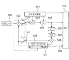
以下、これらの中で、前記H.261勧告による符号化アルゴリズムによる従来の圧縮符号化装置を図7を用いて簡単に説明する。まず、フレーム内符号化では、スイッチ511はAに接続され、入力された符号化対象画像500が、DCT503、量子化部504において、ブロックサイズ8×8でDCT変換され、さらに量子化されて圧縮データとなる。そして、圧縮データ(量子化インデックス)は画像符号化データ505として生成される。
【0005】
また、フレーム間符号化では、スイッチ511はBに接続され、入力された符号化対象画像500が、動きベクトル検出部501に入力され、16画素×16ラインのマクロブロックと称する正方形のブロックに分割される。動きベクトル検出部501では、符号化対象画像500の中の各マクロブロック毎に、参照画像との間の動き量を検出し、得られた動きベクトルのブロック動き補償処理を行う。ここで、各マクロブロックの動きベクトルは、基準方向xおよびそれに垂直な方向yの平行移動量として求められる。すなわち、参照画像においては、着目するマクロブロックとのマッチング度が最も高いブロックの座標と着目するマクロブロックの座標との変位として表される。動きベクトルの探索範囲は、着目するマクロブロックの座標とその周囲の±15画素×±15ラインに制限される。
【0006】
次に、動きベクトル検出部501では、各マクロブロック毎に動きベクトル分シフトした座標に位置する局部復号画像を当該ブロックの予測値とし、動き補償予測画像を生成する。ここで得られる動き補償予測画像は符号化対象画像500と共に減算器502に入力される。両者の差分すなわち動き補償予測誤差は、DCT503、量子化部504においてDCT変換され、圧縮差分データとなる。ここでも、DCTのブロックサイズは8×8である。圧縮差分データ(量子化インデックス)は差分画像符号化データ505として生成される。一方、動きベクトルは動きベクトル符号として符号化され、得られた動きベクトル符号化データ506は差分画像符号化データ505と共に多重化部510にて多重化され、多重化データとして伝送される。
【0007】
なお、復号器と同じ復号画像を符号器内でも得るため、圧縮差分データ(量子化インデックス)505は逆量子化部506で量子化代表値に戻され、さらに逆DCT変換部507で逆DCTされた後、復号差分画像となる。復号差分画像と動き補償画像は加算器508で加算され、局部復号画像となる。この局部復号画像はフレームメモリ509に蓄積され、次のフレームの符号化時に参照画像として用いられる。前記各制御を行う符号化制御部515の制御データも同時に、多重化部510に送られる。
【0008】
H.261勧告では、符号化された画像データの発生量を制御するため、情報源符号器入力前の処理系、量子化器、有意ブロック判定、コマ落とし制御など、いくつかのパラメータは可変となっている。また、フレーム間符号化とフレーム内符号化の選択方法などは、どのように用いられるかは規定されていない。
【0009】
従来の方法は、図8に示すように、(a)が入力画像を表しており、(b)が符号化方法を表し、Iがフレーム内符号化、Pがフレーム間符号化を表す。(a)のV1・V2・V3・V4・・・V53・・・のフレームが入力された時、まず、V1をフレーム内符号化を行い、これを参照画面としてV4をフレーム間符号化、V5をフレーム間符号化、V6をフレーム間符号化・・・と行う。ある一定回数以上のフレーム間符号化を行うか、入力画面間の相関性が著しく低下した場合、再びフレーム内符号化を行い(V50)フレーム間符号化を実行する。図8の例では、V2、V3、V51、V52はコマ落とし(伝送されない)フレームを表す。
【0010】
【発明が解決しようとする課題】
しかしながら、上記従来例の画像圧縮技術を用いても、伝送容量がかなり低い(たとえば64kbps程度)条件では、コマ落としが多くなる、あるいは伝送画像の品位がかなり悪くなる。通信により簡易的に相手先の画像を確認するテレビ会議システムなどでは十分な画質も、記録、保存を要求する画質は満足されていない。このため伝送画像枚数と画像品質とのバランスを最適条件にするための提案がいくつかなされているが、いずれも、符号化の処理が複雑になり、処理時間、回路規模が膨大になり、高価で大きいものとなってしまうなど問題が多かった。
【0011】
従って、本発明の目的は、安価、小回路規模で、保存に耐えうる高画質の画像を、低い伝送容量においても、操作性を損なうことなく伝送することである。
【0012】
【課題を解決するための手段】
本発明は、入力される映像信号を圧縮符号化する画像処理装置であって、フレーム内符号化手段と、フレーム間符号化手段と、上記映像信号を上記フレーム内符号化手段またはフレーム間符号化手段により圧縮符号化された圧縮データを蓄積する蓄積手段と、上記蓄積手段により蓄積された蓄積圧縮データを出力する出力手段と、上記フレーム内符号化手段と上記フレーム間符号化手段とを用いて上記映像信号を間引き符号化し、上記蓄積手段に蓄積し、上記出力手段より出力する第1の動作モードと、上記フレーム内符号化手段と上記フレーム間符号化手段とを用いて上記映像信号を間引きせずに符号化し、上記蓄積手段に蓄積し、上記出力手段より上記蓄積手段内の上記フレーム内符号化手段により符号化された圧縮データを出力する第2の動作モードと、上記第2の動作モード時に符号化し上記蓄積手段に蓄積した、上記蓄積手段内の残りの圧縮データを、上記第2の動作モードではなくさらに上記残りの圧縮データを有するときに出力する第3の動作モードと、を制御する制御手段と、を備えることを特徴とする。
【0013】
また、本発明は、入力される映像信号を圧縮符号化する画像処理装置のコンピュータに、フレーム内符号化手順と、フレーム間符号化手順と、上記映像信号を上記フレーム内符号化手順またはフレーム間符号化手順により圧縮符号化された圧縮データを蓄積手段に蓄積する蓄積手順と、上記蓄積手順により蓄積された蓄積圧縮データを出力する出力手順と、上記フレーム内符号化手順と上記フレーム間符号化手順とを用いて上記映像信号を間引き符号化し、上記蓄積手段に蓄積し、上記出力手順より出力する第1の動作モードと、上記フレーム内符号化手順と上記フレーム間符号化手順とを用いて上記映像信号を間引きせずに符号化し、上記蓄積手段に蓄積し、上記出力手順より上記蓄積手段内の上記フレーム内符号化手順により符号化された圧縮データを出力する第2の動作モードと、上記第2の動作モード時に符号化し上記蓄積手段に蓄積した、上記蓄積手段内の残りの圧縮データを、上記第2の動作モードではなくさらに上記残りの圧縮データを有するときに出力する第3の動作モードと、を制御する制御手順と、を実行させるためのプログラムを記憶したコンピュータ読み取り可能な記憶媒体である。
【0016】
【発明の実施の形態】
以下、本発明の実施の形態を図面と共に説明する。
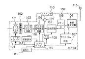
図1、図2は本発明を適用した画像伝送システムのブロック図であり、図1の150は送信側の本発明による画像処理装置としてのカメラ部、図2の250は受信側のモニタ部である。カメラ部150において、101は映像を取り込むレンズ、102は映像を結像する撮像素子、103は映像をサンプルホールドし適正レベルに増幅するCDS/AGC回路、104はレンズ101をズーミングあるいはフォーカシングのため駆動するモータドライバである。
【0017】
105は映像信号をデジタル処理するデジタル信号処理回路、106はデータを伝送する無線送受信機、107は通信を制御するプロトコル回路、108はキャラクタ信号を発生させるキャラクタジェネレータ、110は映像などを表示するファインダ、111はビデオカメラの操作キー、112は映像情報の圧縮回路、109は圧縮データを蓄積するメモリ、113はアンテナ、114は映像信号とキャラクタ信号のミックス回路、115はシステムを制御するカメラマイコンである。
【0018】
116は本発明を構成する記憶媒体であり、後述する図6、図8の処理を実行するための制御プログラムを格納している。この上記記憶媒体116としては、半導体メモリ、光ディスク、光磁気ディスク、磁気媒体等を用いてよく、これらをROM、RAM、CD−ROM、フロッピディスク、メモリカード、磁気カード等に構成して用いてよい。
【0019】
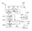
モニタ部250において、201はアンテナ、202は映像信号などを送受信する無線送受信機、203は通信を制御するプロトコル制御部、211は映像情報の伸長回路、204はデジタル信号処理回路、205は記録再生回路、206はシステムを制御するモニタマイコン、207はモニタマイコン206の操作キー、208は映像信号とキャラクタ信号のミックス回路、209は映像などを表示するファインダとしての表示器、210はキャラクタ信号を発生させるキャラクタジェネレータ、212は受信データを蓄積するメモリである。
【0020】
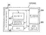
図3は上記プロトコル回路107(203も同一構成)の詳細を示したブロック図であり、301は制御入出力とシステムデータのシステムインターフェース部、302はプロトコルを制御するコントローラ部、303はプロトコル回路内のバスとメモリを制御するメモリ/バスコントローラ部、306は内部メモリ、304は伝送路のデータプロトコルのインターフェースを制御するデータリンクコントローラ部、305はエラー検出またはエラー訂正のデータを、生成または処理するECCエンコーダ/デコード部である。各ブロックは内部アドレスバス、データバスとコントロールバスで接続されている。
【0021】
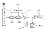
図4は図2の伸長回路211の詳細を示したブロック図であり、400は符号化データ入力部、401は各ブロックを制御する復号化制御部、402は逆量子化部、403は逆DCT回路部、404はデータ合成部、405は復号化データ出力部、406は予測メモリ、407は切り替えスイッチである。
【0022】
次に動作について説明する。
図1において、カメラ部150の各操作は、操作キー111により行われ、カメラ部150の撮影時には、被写体がレンズ101から撮像素子102で結像する。映像信号はCDS/AGC回路103でサンプル/増幅され、デジタル信号処理回路105に入力される。レンズ101はズーミングやフォーカシングのために、カメラマイコン115の制御命令を受けて、モータドライバ104で駆動される。
【0023】
一方、撮影データ(テープカウンタ、各種警告、撮影モードなど)が、カメラマイコン115からキャラクタジェネレータ108を介してキャラクタ信号として生成される。デジタル信号処理回路105からの映像信号とキャラクタジェネレータ108からのキャラクタ信号とがミックス回路114で合成されて、ファインダ110で表示される。
【0024】
また、デジタル信号処理回路105からの映像信号は、圧縮回路112で圧縮され、プロトコル回路107あるいはメモリ109に送られる。ここで用いる圧縮方法は、従来例で説明した手法と同様であり、フレーム内符号化とフレーム間符号化とを、伝送容量、画質、動きに応じて最適に切り替える方法である。
【0025】
また、カメラマイコン115から送られる各種付加情報もプロトコル回路107へ送られる。カメラマイコン115によって制御されたプロトコル回路107が、後述する伝送プロトコルに従って無線送受信機106に送られ、ここで無線送受信機106で無線データに変換され、アンテナ113を通して伝送される。
【0026】
この時、カメラ部150が、操作キー111あるいは動作モード制御信号によって、記録モードと設定された場合は、圧縮データ中のフレーム内符号化データのみを、無線伝送する。このとき圧縮データ中のフレーム間符号化データは、メモリ109に蓄積され続ける。
【0027】
その後、カメラ部150が、操作キー111あるいは制御信号によって記録モード終了と設定された場合は、メモリ109に蓄積されたフレーム間符号化データを随時、無線伝送する。メモリ109に蓄積された記録モード中のフレーム間符号化データが送出終了したならば、通常伝送へと移行する。
【0028】
また、受信時には、アンテナ113より受信された無線データは、無線送受信機106で復調されてプロトコル回路107に送られる。その中で、必要なデータがカメラマイコン115へ送られる。この信号の中に、上記動作モード制御信号が含まれる。
【0029】
次に図2のモニタ部250の動作説明の前に、伸長回路211の動作について、図4を用いて説明する。符号化データ入力部400から入力された符号データは、制御信号と画像符号データとに分離され、制御信号は復号化制御部401に入力される。まず、フレーム内符号化データであれば、スイッチ407がAに接続され、逆量子化回路402で逆量子化され、逆DCT回路402で逆DCTされた復号化データが、復号化データ出力部405へ出力される。同時に、予測メモリ406に参照復号化データとして蓄積される。
【0030】
フレーム間符号化データの場合は、スイッチ407がBに接続され、逆量子化回路402で逆量子化され、逆DCT回路402で逆DCTされた差分復号化データが、予測メモリ406とデータ合成部404で合成され、復号化データ出力部405へ出力される。同時に予測メモリ406に参照復号化データとして蓄積される。
【0031】
図2のモニタ部250において、アンテナ201より受信された無線データは、無線送受信機202で復調されてプロトコル回路208あるいはメモリ212に送られる。通常伝送モードであれば、映像符号化情報は、伸長回路211でフレーム内符号化データとフレーム間符号化データとを適切に復号された後、デジタル信号処理回路204へ送られ、ミックス回路208を通してファインダ209に復号画像が表示される。
【0032】
記録伝送モード(カメラ部150が記録モードで、伝送データがフレーム内符号化の時)であれば、受信されたフレーム内符号化データを伸長回路211で随時復号して、復号データをメモリ212に復号データAとして蓄積する。一方、復号データは、デジタル信号処理回路204へ送られミックス回路208を通してファインダ209に表示される。
【0033】
記録伝送モード終了時(カメラ部150が記録モード終了で、受信データが記録モード中のフレーム間符号化データの時)であれば、受信されたフレーム間符号化データをメモリ212に符号データBとして蓄積する。そして、通常伝送モードに戻った時、上記記録伝送モード中の復号データAと符号データBとを再構成して、デジタル信号処理回路204へ送り、記録再生装置205で記録される。
【0034】
この再編成の処理方法は、復号データA内のフレーム画像間の符号データBを復号して中間復号データCを得る。そして、復号データA内のフレーム画像を参照画像として上記復号データCから記録時の復号データDを導き出し、復号データAと復号データDとを合成する処理で行われる。また、フレーム間符号化データの受信から、データ再構築をして記録までの処理時間が操作性に問題を及ぼす時は、ファインダ209に”処理中”などの注意表示を示すことも操作性上有効である。
【0035】
各種受信付加情報は、モニタマイコン206に送られる。表示の付加情報では、キャラクタジェネレータ210で発生した信号と映像信号が、ミックス回路208でミックスされ、ファインダ209で表示される。記録の付加情報では、記録モードであれば記録再生装置205に記録される。
【0036】
また送信時に、モニタマイコン206からプロトコル回路203に動作モード制御データなどの信号が送られ、無線送受信機202で無線データに変換されてアンテナ201から送信される。
【0037】
次に、プロトコル回路107及び203について、図3を用いて説明する。各マイコン115、206とは、システムインターフェース301を等しく内部バスに接続され、コントローラ302と制御、各種付加情報のやりとりを行う。伝送路で送受信するデータもシステムインターフェース301から入出力され、内部バスと接続される。メモリ/バスコントローラ部303はプロトコル回路内部のバスを制御したり、作業用あるいはバッファメモリなどに使用されるメモリ306の詳細なコントロールを行う。
【0038】
また、ECCエンコード/デコード305は、データのエラー検出あるいはエラー訂正のために動作し、伝送路の送信時においては、情報本体データにパリティ情報の生成付加を行う。伝送路の受信時においては、得られたデータからエラー検出、訂正を行う。ECCの方式においては、公知のハミング符号、BCH符号、リードソロモン符号、ビタビ畳み込み符号などを使用する。コントローラ302に制御されたデータリンクコントローラ304が、送信時のデータパケットフレームの組立、受信時のデータ抽出など行い、後述する伝送プロトコルで伝送路に対しての送受信を行う。
【0039】
ここで、本実施の形態による伝送プロトコルについて説明する。ここではキャリアセンス方式とRTS/CTS方式を採用している。まず、キャリアセンスとは、各局が自局の電波と他局からの電波との干渉を避けるために、通信を行う前に他局から電波が出されているか否かを一定時間にチェックすることである。キャリアセンス時間内に他局からの電波が検出されなければ通信を開始し、他局からの電波が検出されれば、さらにキャリアセンスを続ける。キャリアセンス後のプロトコルとして、送信要求信号及び応答信号を用いる。これは送信側の局がキャリアセンスを行った後、先ず送信要求信号RST(REQUEST TO SEND)を相手局に送り、これに応じて相手局は応答信号CTS(CLEAR TO SEND)を送り、送信側の局は所定時間内にCTSを受信した時、データの送信を開始する方式である。
【0040】
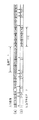
図5は第1の実施の形態による動作を説明するタイミングチャートである。(a)は図1のカメラ部150の入力画像を示し、V10、V11、V12・・・と連続して入力されている。(画像はフィールド画あるいはフレーム画のどちらでもよい)(b)は各入力画像に対する符号化方法と伝送符号化データを示し、Iはフレーム内符号化、Pはフレーム間符号化を示す。
【0041】
まず、通常モードでは、最初の入力画像V10をフレーム内符号化した後、伝送容量、画質、動きなどに応じて適切にフレーム間符号化、フレーム内符号化を行う。図5では、V13、V14はフレーム間符号化を行い、V50はフレーム内符号化を行うことを示している。
【0042】
V55において、カメラ部150が記録モードに移行した時、記録モード中はV55、V59などのフレーム内符号化データのみを伝送して、V56、V57、V58、V60、V61、V62などのフレーム間符号化データは、メモリ109に蓄積する。記録モード終了時以降、上記メモリ109に蓄積されたフレーム間符号化データP56、P57、P58、P60、P61、P62をT10期間に伝送する。上記フレーム間符号化データ伝送後、通常伝送モードに移行する。
【0043】
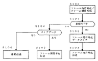
図6は第1の実施の形態の動作を説明するフローチャートである。S100でフレーム内符号化、フレーム間符号化を随時行い、S101で記録モードかを判別する。記録モードならば、S102でフレーム間符号化されたデータをメモリ109にストアする。そして、S103でフレーム内符号化データのみを伝送する。S102で記録モードでなければ、S103で、メモリ109に蓄積されているフレーム間符号化データが存在するか確認する。存在していればS105でフレーム間符号化データを伝送する。そうでてければ、S106の通常伝送を行う。
【0044】
上記第1の実施の形態により、通常伝送中は、伝送容量に適したデータ伝送量でフレーム内符号化、フレーム間符号化を行い、記録モード伝送中は、記録保存に適した高画質を記録することが可能になる。また、記録伝送中の画像も随時表示可能であり、操作性も損なうことがないなどの効果がある。
【0058】
【発明の効果】
以上説明したように、請求項1、3の発明によれば、通常伝送では互換性の高い圧縮方式を採用することで汎用回線との接続が容易になり、また記録モードのような保存に耐え得る高画質の画像の伝送要求に対しても、安価、小回路規模で実現できる。また、低い伝送容量においても、操作性を損なうことなく伝送することができるなどの効果がある。
【0060】
さらに、請求項2、4、7、9の発明によれば、高画質伝送中に蓄積した画像を伝送終了後に出力して表示することができる。
【図面の簡単な説明】
【図1】 本発明の実施の形態を示すブロック図である。
【図2】 モニタ部を示すブロック図である。
【図3】 プロトコル回路を示すブロック図である。
【図4】 伸長回路を示すブロック図である。
【図5】 本発明の第1の実施の形態の動作を説明するタイミングチャートである。
【図6】 本発明の第1の実施の形態の動作を説明するフローチャートである。
【図7】 従来の圧縮符号化装置を示すブロック図である。
【図8】 従来の動作を説明するタイミングチャートである。
【符号の説明】
105 デジタル信号処理回路
106 無線送受信機
107 プロトコル回路
109 メモリ
111 操作キー
112 圧縮回路
113 アンテナ
115 カメラアイコン
150 カメラ部[0001]
BACKGROUND OF THE INVENTION
The present invention relates to an image processing apparatus for compressing and transmitting a video signal and a computer-readable storage medium.
[0002]
[Prior art]
In recent years, the development of image compression coding technology, the spread of digital communication lines, and the innovation of semiconductor technology are remarkable. Also, video encoding for storage (ISO / IEC11172 (MPEG-1)), general-purpose video encoding for storage, broadcasting and communication (ISO / IEC13818 (MPEG-2)), video encoding for communication (ITU-T recommendation H) .261 / H.263) is recommended, and various video / audio terminal devices such as a TV phone device and a TV conference system have been proposed. Furthermore, in order to directly digitally transmit moving image information, a transmission rate of several hundred Mbps is required, so various compression encoding methods that reduce the transmission rate and reduce the transmission cost have been proposed.
[0003]
The compression coding method of moving image information in these moving image communications includes inter-frame coding that uses temporal correlation to remove temporal redundancy, and orthogonal transform coding that uses spatial correlation. A hybrid encoding method combined with intra-frame encoding that removes spatial redundancy is often used. Interframe coding includes motion compensation interframe coding that compensates for motion between frames and interframe coding that does not compensate for motion.
[0004]
Hereinafter, among these, H. A conventional compression encoding apparatus based on an encoding algorithm according to the H.261 recommendation will be briefly described with reference to FIG. First, in intra-frame coding, the
[0005]
In interframe coding, the
[0006]
Next, the motion
[0007]
In addition, in order to obtain the same decoded image as the decoder in the encoder, the compressed differential data (quantization index) 505 is returned to the quantized representative value by the
[0008]
H. In the H.261 recommendation, in order to control the generation amount of encoded image data, some parameters such as a processing system before input of an information source encoder, a quantizer, significant block determination, and frame drop control are variable. Yes. In addition, how to select interframe coding and intraframe coding is not defined.
[0009]
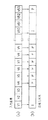
In the conventional method, as shown in FIG. 8, (a) represents an input image, (b) represents an encoding method, I represents intraframe coding, and P represents interframe coding. When the frame of V1, V2, V3, V4,..., V53,... Of (a) is input, first, V1 is subjected to intraframe coding, V4 is interframe coded using this as a reference screen, and V5. Are inter-coded, V6 is inter-coded, and so on. When the inter-frame coding is performed a certain number of times or when the correlation between the input screens is remarkably reduced, intra-frame coding is performed again (V50) and the inter-frame coding is executed. In the example of FIG. 8, V2, V3, V51, and V52 represent frames that are dropped (not transmitted).
[0010]
[Problems to be solved by the invention]
However, even if the conventional image compression technique is used, frame dropping is increased or the quality of the transmitted image is considerably deteriorated under the condition that the transmission capacity is very low (for example, about 64 kbps). In a video conference system or the like that simply confirms the image of the other party through communication, sufficient image quality is not satisfied, but image quality that requires recording and storage is not satisfied. For this reason, some proposals have been made to optimize the balance between the number of transmitted images and the image quality, but all of them are complicated in encoding processing, enormously processing time and circuit scale, and expensive. There were many problems such as becoming big.
[0011]
Therefore, an object of the present invention is to transmit a high-quality image that can be stored at low cost with a small circuit scale, even in a low transmission capacity, without impairing operability.
[0012]
[Means for Solving the Problems]
The present invention is an image processing apparatus for compressing and encoding a video signal input, and intraframe coding means, encoding means inter-frame, inter-symbol upper Symbol intraframe coding means or frame the video signal means for storing the compressed data compressed and encoded by means, and output means for outputting the stored compressed data accumulated by said accumulating means, the encoding means between the upper Symbol intraframe coding means and said frame encoding thinning said video signal using, accumulated in said accumulating means, said image by using a first operation mode in which the output from the output means, the encoding means between the upper Symbol intraframe coding means and said frame coded without thinning out the signal, accumulated in the accumulation means, outputs the compressed data encoded by the intra-frame coding means in said storage means from above SL output means first And operation mode, the accumulated in the second operating mode encoded the storage means at the time, the rest of the compressed data in the storage means, when having further the remaining compressed data rather than the second mode of operation And a control means for controlling the third operation mode to be output.
[0013]
Further, the present invention causes a computer of an image processing apparatus for compressing and encoding a video signal input, intraframe catheter order and inter-frame coding catheter order and, in the upper Symbol frame the video signal encoding catheter a storage procedure for storing the compressed data compressed and encoded by forward or inter-frame coding catheter order of storage means, and output steps of outputting the stored compressed data accumulated by the accumulation steps, the upper Symbol frame encoding thinning said video signal by using the code catheter order and the inter-frame coding catheter order, accumulated in the accumulation means, a first operation mode in which the output from the output instructions, the upper Symbol intraframe coded without thinning out the video signal by using the catheter order and the inter-frame coding catheter order, accumulated in the accumulation means, in the frame in the storage means from the above SL output procedure codes catheter encoded by the order And a second operation mode for outputting the compressed data, accumulated in the encoded said storage means to said second operation mode, the remaining compressed data in the storage means, further the remaining instead of the second mode of operation a third computer readable storage medium storing a program for executing an operation mode, and a control procedure for controlling the output to the time with the compressed data.
[0016]
DETAILED DESCRIPTION OF THE INVENTION
Embodiments of the present invention will be described below with reference to the drawings.
1 and 2 are block diagrams of an image transmission system to which the present invention is applied. 150 in FIG. 1 is a camera unit as an image processing apparatus according to the present invention on the transmission side, and 250 in FIG. 2 is a monitor unit on the reception side. is there. In the
[0017]
105 is a digital signal processing circuit for digitally processing video signals, 106 is a wireless transceiver for transmitting data, 107 is a protocol circuit for controlling communication, 108 is a character generator for generating character signals, and 110 is a viewfinder for displaying video and the like. 111 is a video camera operation key, 112 is a video information compression circuit, 109 is a memory for storing compressed data, 113 is an antenna, 114 is a video signal and character signal mixing circuit, and 115 is a camera microcomputer for controlling the system. is there.
[0018]
[0019]
In the
[0020]
FIG. 3 is a block diagram showing details of the protocol circuit 107 (203 has the same configuration), 301 is a system interface unit for control input / output and system data, 302 is a controller unit for controlling the protocol, and 303 is in the protocol circuit. A memory / bus controller unit for controlling the bus and the memory of the device, 306 is an internal memory, 304 is a data link controller unit for controlling a data protocol interface of the transmission path, and 305 generates or processes error detection or error correction data. An ECC encoder / decode unit. Each block is connected by an internal address bus, a data bus, and a control bus.
[0021]
4 is a block diagram showing details of the decompression circuit 211 in FIG. 2, in which 400 is an encoded data input unit, 401 is a decoding control unit for controlling each block, 402 is an inverse quantization unit, and 403 is an inverse DCT. A circuit unit, 404 is a data synthesis unit, 405 is a decoded data output unit, 406 is a prediction memory, and 407 is a changeover switch.
[0022]
Next, the operation will be described.
In FIG. 1, each operation of the
[0023]
On the other hand, shooting data (tape counter, various warnings, shooting mode, etc.) is generated as a character signal from the
[0024]
The video signal from the digital
[0025]
Various additional information sent from the
[0026]
At this time, when the
[0027]
Thereafter, when the
[0028]
At the time of reception, the wireless data received from the
[0029]
Next, the operation of the decompression circuit 211 will be described with reference to FIG. 4 before describing the operation of the
[0030]
In the case of inter-frame encoded data, the
[0031]
In the
[0032]
In the recording transmission mode (when the
[0033]
When the recording / transmission mode ends (when the
[0034]
In this reorganization processing method, code data B between frame images in the decoded data A is decoded to obtain intermediate decoded data C. Then, the decoding data D at the time of recording is derived from the decoding data C using the frame image in the decoding data A as a reference image, and the decoding data A and the decoding data D are synthesized. In addition, when the processing time from reception of inter-frame encoded data to data reconstruction and recording has a problem with operability, a caution display such as “processing in progress” may be displayed on the
[0035]
Various reception additional information is sent to the
[0036]
At the time of transmission, a signal such as operation mode control data is transmitted from the
[0037]
Next, the
[0038]
The ECC encode / decode 305 operates for data error detection or error correction, and generates and adds parity information to the information main body data during transmission on the transmission path. When receiving the transmission line, error detection and correction are performed from the obtained data. In the ECC system, a known Hamming code, BCH code, Reed-Solomon code, Viterbi convolutional code, or the like is used. A
[0039]
Here, the transmission protocol according to the present embodiment will be described. Here, the carrier sense method and the RTS / CTS method are adopted. First, with carrier sense, each station checks whether or not radio waves are emitted from other stations at a certain time before communication to avoid interference between its own radio waves and radio waves from other stations. It is. If radio waves from other stations are not detected within the carrier sense time, communication is started. If radio waves from other stations are detected, carrier sense is further continued. A transmission request signal and a response signal are used as a protocol after carrier sense. This is because, after the transmitting station performs carrier sense, first, a transmission request signal RST (REQUEST TO SEND) is sent to the counterpart station, and in response thereto, the counterpart station sends a response signal CTS (CLEAR TO SEND). This station starts transmission of data when CTS is received within a predetermined time.
[0040]
FIG. 5 is a timing chart for explaining the operation according to the first embodiment. (A) shows the input image of the
[0041]
First, in the normal mode, after the first input image V10 is intra-frame encoded, inter-frame encoding and intra-frame encoding are appropriately performed according to transmission capacity, image quality, motion, and the like. In FIG. 5, V13 and V14 indicate inter-frame encoding, and V50 indicates that intra-frame encoding is performed.
[0042]
In V55, when the
[0043]
FIG. 6 is a flowchart for explaining the operation of the first embodiment. In S100, intra-frame encoding and inter-frame encoding are performed as needed, and in S101, it is determined whether the recording mode is set. If it is the recording mode, the inter-frame encoded data in S102 is stored in the
[0044]
According to the first embodiment, during normal transmission, intra-frame encoding and inter-frame encoding are performed with a data transmission amount suitable for the transmission capacity, and during recording mode transmission, high image quality suitable for recording and storage is recorded. It becomes possible to do. Further, an image during recording / transmission can be displayed at any time, and there is an effect that operability is not impaired.
[0058]
【The invention's effect】
As described above, according to the first and third aspects of the invention, a compression system having high compatibility is adopted in normal transmission, so that connection with a general-purpose line is facilitated and storage such as a recording mode can be withstood. It can be realized at a low cost and with a small circuit scale in response to a transmission request for a high quality image to be obtained. In addition, even with a low transmission capacity, there is an effect that transmission can be performed without impairing operability.
[0060]
Furthermore, according to the inventions of
[Brief description of the drawings]
FIG. 1 is a block diagram showing an embodiment of the present invention.
FIG. 2 is a block diagram illustrating a monitor unit.
FIG. 3 is a block diagram showing a protocol circuit.
FIG. 4 is a block diagram showing a decompression circuit.
FIG. 5 is a timing chart for explaining the operation of the first exemplary embodiment of the present invention.
FIG. 6 is a flowchart for explaining the operation of the first exemplary embodiment of the present invention.
FIG. 7 is a block diagram showing a conventional compression encoding apparatus.
FIG. 8 is a timing chart for explaining a conventional operation.
[Explanation of symbols]
105 Digital
Claims (4)
フレーム内符号化手段と、
フレーム間符号化手段と、
上記映像信号を上記フレーム内符号化手段またはフレーム間符号化手段により圧縮符号化された圧縮データを蓄積する蓄積手段と、
上記蓄積手段により蓄積された蓄積圧縮データを出力する出力手段と、
上記フレーム内符号化手段と上記フレーム間符号化手段とを用いて上記映像信号を間引き符号化し、上記蓄積手段に蓄積し、上記出力手段より出力する第1の動作モードと、上記フレーム内符号化手段と上記フレーム間符号化手段とを用いて上記映像信号を間引きせずに符号化し、上記蓄積手段に蓄積し、上記出力手段より上記蓄積手段内の上記フレーム内符号化手段により符号化された圧縮データを出力する第2の動作モードと、上記第2の動作モード時に符号化し上記蓄積手段に蓄積した、上記蓄積手段内の残りの圧縮データを、上記第2の動作モードではなくさらに上記残りの圧縮データを有するときに出力する第3の動作モードと、を制御する制御手段と、
を備えることを特徴とする画像処理装置。An image processing apparatus that compresses and encodes an input video signal,
Intra-frame encoding means;
Interframe encoding means;
It means for storing the compressed data compressed and encoded by the upper Symbol intraframe coding means or inter-frame coding means for the video signal,
Output means for outputting the accumulated compressed data accumulated by the accumulation means;
Encoding thinning said video signal by using the encoding means between the upper Symbol intraframe coding means and the frame, stored in said storage means, a first operation mode in which the output from the output means, the upper Symbol frame by using the encoding means between the coding means and the frame is encoded without thinning the video signal, stored in said storage means, the code from the above SL output means by said intraframe coding means in said storage means A second operation mode for outputting compressed compressed data, and the remaining compressed data in the storage means encoded and stored in the storage means during the second operation mode, instead of the second operation mode. And a control means for controlling the third operation mode to be output when the remaining compressed data is included.
An image processing apparatus comprising:
フレーム内符号化手順と、
フレーム間符号化手順と、
上記映像信号を上記フレーム内符号化手順またはフレーム間符号化手順により圧縮符号化された圧縮データを蓄積手段に蓄積する蓄積手順と、
上記蓄積手順により蓄積された蓄積圧縮データを出力する出力手順と、
上記フレーム内符号化手順と上記フレーム間符号化手順とを用いて上記映像信号を間引き符号化し、上記蓄積手段に蓄積し、上記出力手順より出力する第1の動作モードと、上記フレーム内符号化手順と上記フレーム間符号化手順とを用いて上記映像信号を間引きせずに符号化し、上記蓄積手段に蓄積し、上記出力手順より上記蓄積手段内の上記フレーム内符号化手順により符号化された圧縮データを出力する第2の動作モードと、上記第2の動作モード時に符号化し上記蓄積手段に蓄積した、上記蓄積手段内の残りの圧縮データを、上記第2の動作モードではなくさらに上記残りの圧縮データを有するときに出力する第3の動作モードと、を制御する制御手順と、
を実行させるためのプログラムを記憶したコンピュータ読み取り可能な記憶媒体。 In a computer of an image processing apparatus that compresses and encodes an input video signal ,
And intra-frame coding catheter order,
And inter-frame sign catheter order,
A storage procedure for storing in the storage means compressed data compressed and encoded by the upper Symbol intraframe catheter order or inter-frame coding catheter order of the video signal,
An output procedure for outputting the stored compressed data accumulated by the accumulation procedure,
By using the upper Symbol intraframe catheter order and the inter-frame coding catheter order to encode thinning said video signal, and stored in the storage means, a first operation mode in which the output from the output instructions, above by using the serial intraframe catheter order and the inter-frame coding catheter order coded without thinning out the video signal, stored in said storage means, said frame in said storage means from above Symbol output procedure and a second operation mode for outputting the compressed data by the inner coding catheter order encoded and stored in said storage means encoded into the second operation mode, the remaining compressed data in the storing means, the a third operation mode and controls the control procedure of the output when further comprising the remaining compressed data rather than second operation mode,
The computer-readable storage medium which memorize | stored the program for performing this.
Priority Applications (1)
| Application Number | Priority Date | Filing Date | Title |
|---|---|---|---|
| JP11048598A JP4046844B2 (en) | 1998-04-21 | 1998-04-21 | Image processing apparatus and computer-readable storage medium |
Applications Claiming Priority (1)
| Application Number | Priority Date | Filing Date | Title |
|---|---|---|---|
| JP11048598A JP4046844B2 (en) | 1998-04-21 | 1998-04-21 | Image processing apparatus and computer-readable storage medium |
Publications (3)
| Publication Number | Publication Date |
|---|---|
| JPH11308619A JPH11308619A (en) | 1999-11-05 |
| JPH11308619A5 JPH11308619A5 (en) | 2005-05-26 |
| JP4046844B2 true JP4046844B2 (en) | 2008-02-13 |
Family
ID=14536938
Family Applications (1)
| Application Number | Title | Priority Date | Filing Date |
|---|---|---|---|
| JP11048598A Expired - Fee Related JP4046844B2 (en) | 1998-04-21 | 1998-04-21 | Image processing apparatus and computer-readable storage medium |
Country Status (1)
| Country | Link |
|---|---|
| JP (1) | JP4046844B2 (en) |
-
1998
- 1998-04-21 JP JP11048598A patent/JP4046844B2/en not_active Expired - Fee Related
Also Published As
| Publication number | Publication date |
|---|---|
| JPH11308619A (en) | 1999-11-05 |
Similar Documents
| Publication | Publication Date | Title |
|---|---|---|
| JP5007012B2 (en) | Video encoding method | |
| JP4603695B2 (en) | Video coding | |
| TWI406572B (en) | Error resilient video transmission using instantaneous receiver feedback and channel quality adaptive packet retransmission | |
| JP2008160877A (en) | Encoding method and decoding method of moving picture | |
| US20110170605A1 (en) | Image processing apparatus and image processing method | |
| JP5641377B2 (en) | Image processing apparatus and method, program, and recording medium | |
| JP2011087195A (en) | Image processor and image processing method | |
| JP4792001B2 (en) | Moving picture decoding apparatus, broadcast receiving apparatus, moving picture decoding method | |
| JPH1028236A (en) | Imaging device, display device, and imaging system | |
| JPH0759115A (en) | Method and apparatus for processing of stereo video signal | |
| JP2005110083A (en) | Data processing apparatus and method and encoding apparatus | |
| WO2008035657A1 (en) | Monitor video accumulation system | |
| JPH089347A (en) | Video transmission equipment | |
| US7712119B1 (en) | Multimedia communication terminal | |
| JP4046844B2 (en) | Image processing apparatus and computer-readable storage medium | |
| JP4281950B2 (en) | Video distribution device | |
| JP3483806B2 (en) | Video signal encoding apparatus and encoding method | |
| KR100363550B1 (en) | Encoder and decoder in a wireless terminal for retransmitting a moving picture | |
| JPH07274176A (en) | Video transmission equipment | |
| JPH1070727A (en) | Method and device for transmitting moving picture | |
| JPH11308619A5 (en) | ||
| JP2006109060A (en) | Image stabilization method and apparatus using image coding information | |
| US20120195513A1 (en) | Image processing device and image processing method | |
| JPH114450A (en) | Digital video data transmission system | |
| JPH07336678A (en) | Digital signal transmitter, receiver and transmitter / receiver |
Legal Events
| Date | Code | Title | Description |
|---|---|---|---|
| A521 | Written amendment |
Free format text: JAPANESE INTERMEDIATE CODE: A523 Effective date: 20040722 |
|
| A621 | Written request for application examination |
Free format text: JAPANESE INTERMEDIATE CODE: A621 Effective date: 20040722 |
|
| A131 | Notification of reasons for refusal |
Free format text: JAPANESE INTERMEDIATE CODE: A131 Effective date: 20061024 |
|
| A521 | Written amendment |
Free format text: JAPANESE INTERMEDIATE CODE: A523 Effective date: 20061221 |
|
| A131 | Notification of reasons for refusal |
Free format text: JAPANESE INTERMEDIATE CODE: A131 Effective date: 20070821 |
|
| A521 | Written amendment |
Free format text: JAPANESE INTERMEDIATE CODE: A523 Effective date: 20071018 |
|
| TRDD | Decision of grant or rejection written | ||
| A01 | Written decision to grant a patent or to grant a registration (utility model) |
Free format text: JAPANESE INTERMEDIATE CODE: A01 Effective date: 20071113 |
|
| A61 | First payment of annual fees (during grant procedure) |
Free format text: JAPANESE INTERMEDIATE CODE: A61 Effective date: 20071121 |
|
| FPAY | Renewal fee payment (event date is renewal date of database) |
Free format text: PAYMENT UNTIL: 20101130 Year of fee payment: 3 |
|
| R150 | Certificate of patent or registration of utility model |
Free format text: JAPANESE INTERMEDIATE CODE: R150 |
|
| FPAY | Renewal fee payment (event date is renewal date of database) |
Free format text: PAYMENT UNTIL: 20101130 Year of fee payment: 3 |
|
| FPAY | Renewal fee payment (event date is renewal date of database) |
Free format text: PAYMENT UNTIL: 20111130 Year of fee payment: 4 |
|
| FPAY | Renewal fee payment (event date is renewal date of database) |
Free format text: PAYMENT UNTIL: 20121130 Year of fee payment: 5 |
|
| FPAY | Renewal fee payment (event date is renewal date of database) |
Free format text: PAYMENT UNTIL: 20131130 Year of fee payment: 6 |
|
| LAPS | Cancellation because of no payment of annual fees |