JP4046836B2 - Imaging apparatus and computer-readable storage medium - Google Patents
Imaging apparatus and computer-readable storage medium Download PDFInfo
- Publication number
- JP4046836B2 JP4046836B2 JP07443998A JP7443998A JP4046836B2 JP 4046836 B2 JP4046836 B2 JP 4046836B2 JP 07443998 A JP07443998 A JP 07443998A JP 7443998 A JP7443998 A JP 7443998A JP 4046836 B2 JP4046836 B2 JP 4046836B2
- Authority
- JP
- Japan
- Prior art keywords
- shake
- correction
- imaging
- frequency
- image
- Prior art date
- Legal status (The legal status is an assumption and is not a legal conclusion. Google has not performed a legal analysis and makes no representation as to the accuracy of the status listed.)
- Expired - Fee Related
Links
Images
Landscapes
- Adjustment Of Camera Lenses (AREA)
- Studio Devices (AREA)
Description
【0001】
【発明の属する技術分野】
本発明は、ビデオカメラ等に用いて良好な手振れ等の振れ補正機能を有する撮像装置及びコンピュータ読み取り可能な記憶媒体に関するものである。
【0002】
【従来の技術】
ビデオカメラ等では、高倍率のズームレンズが採用されており、民生用の分野においてもズーム比10倍以上が一般化している。このようなズーム比の拡大に伴い、長焦点側の焦点距離が大きな数値になってくると、長焦点側では手振れ等によるカメラの振れが撮影される画像に与える影響が大きくなり、主被写体が画面内で見苦しく動いてしまう。そこでビデオカメラ等の分野では、手振れ等の影響を取り除く振れ補正機能の実用化が行われてきた。
【0003】
この振れ補正機能は、振れ成分を検出する振れ検出手段と、この検出手段の検出結果に応じて、振れを補正する振れ補正手段を少なくとも含んでいる。このうち振れ検出手段としては、連続するフィールド間、またはフレーム間の画像を比較して画像の動きを検出する電子的な検出方法や、角速度センサ、角加速度センサなどを用いてカメラの動きを直接測定する方法が挙げられる。
【0004】
一方、振れ補正手段としては、光学的に撮影光軸の角度を手振れが除去される方向に調整する光学的振れ補正手段の他に、得られた画像の中から実際に記録又は出力する範囲(切り出し範囲)を電子的に選択する、所謂電子式補正手段等が挙げられる。
【0005】
さて、このような振れ補正機能を搭載しているカメラを三脚に固定して撮影を行う場合、振れ検出手段からのノイズ成分により、本来止まっていなければならない映像がゆらゆらと揺れてしまうことがある。そのため、三脚等安定した場所に設置され固定されたかどうかの振れ判定手段を有し、その判定手段によりカメラが固定されたと判定された場合は、振れ補正の帯域を制限するなどして、ノイズによる映像の揺れを除去する方法が提案されている。
【0006】
この振れ判定手段では、振れ検出手段により検出される振れ信号の大きさと周波数成分から判定する。まず通常の振れ補正時に振れの周波数が所定のしきい値Aより低く、かつ振れ信号のレベルが所定のしきい値Bより小さい状態が所定時間続いた場合に振れ補正に帯域制限をかけ、不要な動きをカットする。この状態を静止モードと呼ぶことにする。逆に静止モード時に、振れの周波数が所定のしきい値Aより高く、かつ振れ信号のレベルが所定のしきい値Bより大きい時は通常補正に戻る。
【0007】
【発明が解決しようとする課題】
しかしながら上記従来例では、三脚等に固定された静止モード中に例えばカメラを指で軽くはじくような振れを与えると、簡単に静止モードから抜けてしまい、再び静止モードに入るまでの間、やはり映像がゆらゆらと揺れてしまい、違和感を与えてしまうことがあるという問題があった。
【0008】
従って、本発明は、静止モード中に不用意に静止モードから抜けてしまうのを防止することを目的とするものである。
【0009】
【課題を解決するための手段】
本発明による撮像装置においては、被写体像を撮像し画像信号を出力する撮像手段と、上記撮像手段の振れを検出する振れ検出手段と、上記振れ検出手段の検出した振れ信号に基づいて上記画像信号の振れを補正する補正手段と、上記振れ信号の周波数を検出する振れ周波数検出手段と、上記検出した振れ周波数が第1のしきい値より小さいとき上記振れ補正手段による補正を制限し、上記振れ周波数が第2のしきい値より大きいとき上記制限を解除する制御手段とを設けている。
【0010】
本発明による記憶媒体においては、被写体像を撮像し画像信号を出力する撮像処理と、上記撮像手段の振れを検出する振れ検出処理と、上記振れ検出処理で検出した振れ信号に基づいて上記画像信号の振れを補正する補正処理と、上記振れ信号の周波数を検出する振れ周波数検出処理と、上記検出した振れ周波数が第1のしきい値より小さいとき上記振れ補正処理による補正を制限し、上記振れ周波数が第2のしきい値より大きいとき上記制限を解除する制御処理とを実行するためのプログラムを記憶している。
【0011】
【発明の実施の形態】
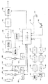
図1は本発明による撮像装置の実施の形態を示す構成図である。
図1において、101は第1のレンズ群であり、集光のための固定レンズ群である。102は第2のレンズ群であり、変倍のために光軸方向に移動可能な変倍レンズ群である。103は絞り、104は第3のレンズ群であり、固定レンズ群である。105は第4のレンズ群であり、変倍レンズ群102の動きで移動した結像位置を補正する機能と焦点調節を行う機能とを兼ね備えた補正レンズ群で、やはり光軸方向に移動可能となっている。これらのレンズ群によるレンズユニットによって、最終的に撮像センサとしてのCCD111の撮像面上に可変倍率の被写体像が結像される。
【0012】
121はモータ、126はモータドライバであり、モータドライバ126によりモータ121を駆動することにより変倍レンズ群102を移動させる。補正レンズ群105に関しても同様に、125のモータ、128のモータドライバにより移動させる。123はIGメータ、127はIGドライバである。
本実施の形態では、モータ121、125はステッピングモータを想定しており、基準位置からのパルス数をカウントすることにより絶対位置を検出する。
尚、その他のアクチュエータを用いる場合は、必要に応じて位置検出センサが必要である。
【0013】
111はCCD(charge coupled device)であり、光を電荷に変換する。ここではCCD111は放送方式(例えばNTSC方式)で必要とする標準のCCDに比べて画素数(光電変換素子数)の多いCCDを用いている。116はCCD駆動回路であり、CCD111を駆動する。CCD駆動回路116は後述のマイクロコンピュータ117からの制御命令に従い、どのラインから最終的に出力するエリアを切り出すかをV方向に関して選択することができるように工夫されている。
【0014】
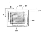
図3において、301はCCDの全イメージサイズIs 、302、303、304は放送方式に準ずる標準イメージサイズIN の例である。例えば最上ラインからΔy1ライン下のラインy1+1から有効とする場合、Δy1ラインを高速に読み出し、垂直同期信号に対し標準サイズのCCDを用いた場合と同じタイミングでy1+1から読み出すことができる。
【0015】
図1において、112はアナログ信号処理部であり、CCD111で得られた信号に所定の処理を施しアナログ画像信号を生成する。例えばCDS回路(correlated double sampling相関二重サンプリング回路)、AGC回路等を含んで構成される。113はA/Dコンバータであり、アナログ画像信号をデジタル画像信号に変換する。114はメモリであり、デジタル画像信号を少なくとも1ライン分記憶することができ、さらに所定の位置(アドレス)から読み出すことが可能である。115はデジタル信号処理部であり、最終的な出力画像信号を生成する。
【0016】
なお、メモリ114に記憶されるデジタル画像信号は、標準イメージサイズに比べて画素数が多いままである。デジタル信号処理部115は後述のマイクロコンピュータ117からの制御命令に従い、メモリ114から読み出す先頭の画素を選択することができ、標準イメージサイズ分だけ読み出すように工夫されている。
【0017】
117はマイクロコンピュータであり、カメラシステム全体の制御を行う。例えばモータトライバ126、128を制御する。また駆動したパルス数を常に監視し、基準位置からの絶対位置を表す変倍レンズ位置データ、補正レンズ位置データをそれぞれ生成する。例えば全ストロークを1280パルスで移動できるとすると、10パルス毎に等分し、128段階の位置データを生成する。140はズームキーであり、ユーザが焦点距離を変える時に操作するキーである。マイクロコンピュータ117はズームキー140の信号を読み込み、それに応じて変倍レンズ103を制御する。
【0018】
131は角速度センサであり、カメラの振れ(CCD111の振れ)の一方向の角速度成分を検出する。132はHPF(高域通過フィルタ)、133はアンプ、134はLPF(低域通過フィルタ)であり、これらにより角速度センサ131で検出された角速度センサ出力信号に対して所定の周波数制限と増幅が施され、角速度信号を生成する。
【0019】
135は角速度センサであり、やはりカメラの振れの他方向の角速度成分を検出する。136はHPF(高域通過フィルタ)、137はアンプ、138はLPF(低域通過フィルタ)であり、上記131〜134の各部と同等の機能を有する。但し、両者はCCD111の撮像面において互いに直行する成分を検出するように配置されている。具体的には一方が縦(V)方向、他方が横(H)方向を検出する。
【0020】
マイクロコンピュータ117はA/Dコンバータを内蔵しており、2方向の角速度信号はこの内蔵A/Dコンバータによりデジタル信号に変換され角速度データとなる。さらに角速度データに所定の信号処理を施し、縦方向、横方向の振れ補正信号を生成する。マイクロコンピュータ117は縦方向の振れ補正信号をCCD駆動回路116に、横方向の振れ補正信号をデジタル信号処理部115にそれぞれ伝達する。先に述べたようにCCD駆動回路116、デジタル信号処理部115はそれぞれ振れ補正信号に応じて切り出す位置を可変する。
【0021】
上記の一連の動作により、図3に示すように全イメージサイズIs 301から、例えば302、304のように標準イメージサイズIN を中央からずらして切り出すことができ、この結果手振れ等による振れを補正することが可能となる。
【0022】
143は上記マイクロコンピュータの制御プログラムを格納する本発明による記憶媒体である。制御プログラムとしては、後述する図2、4に示す処理を実行するためのプログラムを含む。この記憶媒体143としては、半導体メモリ、光ディスク、光磁気ディスク、磁気媒体等を用いてよい。また、それらをROM、RAM、CD−ROM、メモリカード、フロッピディスク、磁気テープ、磁気カード等に構成して用いてよい。
【0023】
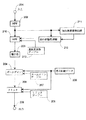
次にマイクロコンピュータ117内の角速度データを振れ補正信号に変換する信号処理について図2を用いて説明する。なお、縦方向、横方向はそれぞれ同じ処理を施すので、ここでは一方向に関して説明する。
まず、処理201により角速度データが取り込まれる。
処理202はHPF(高域通過フィルタ)であり、角速度データから主に直流成分を遮断する。従って、遮断周波数は十分に低い。処理210はHPF(高域通過フィルタ)であり、213は遮断周波数テーブルである。HPF210は遮断周波数を遮断周波数テーブル213より選択することができる。
【0024】
処理203は積分器であり、HPF出力を積分することにより角変位信号を出力する。処理204はズームゲインを乗算し補正量を出力する。カメラに角変位θだけ振れが加わると焦点距離1と撮像面上での被写体移動量Δxには、
Δx=1×tanθ ………(1)
となるので、それぞれの焦点距離に合わせた利得をここで乗算する。205は焦点距離データであり、先に述べたように実際には変倍レンズの位置を有限数(例えば0から128)で表している。
【0025】
207はズームゲインテーブルであり、焦点距離データとズームゲインが対応付けられ、ROM領域に記憶されている。ズームゲイン204は焦点距離データ205の利得をズームゲインテーブル207から読み出す。処理206はリミッタであり、ズームゲイン204の出力値に制限をかけ、補正量を出力する。208はリミッタテーブルであり、焦点距離データとリミッタ値(ずらせる画素数)が対応付けられ、ROM領域に記憶されている。リミッタ206は焦点距離データ205に対応するリミッタ値をリミッタテーブル207から読み出し、ズームゲイン204の出力とリミッタ値とを比較し、リミッタ値よりも大きい場合にリミッタ値を補正量として出力する。
【0026】
211は振れ周波数検出器であり、HPF202の出力信号から振れ周波数成分を検出する。振れ周波数検出器211は最も大きく検出された周波数データを出力する。212は振れ状態判別器であり、HPF202の出力信号と、振れ周波数検出器211からの振れ周波数データとから、振れ状態を判別し、HPF210の遮断周波数を制御する。本実施の形態では振れ判別器により、補正モードと静止モードのどちらかに切り替わる。補正モードとは通常の振れ補正をするモードであり、静止モードとは三脚等安定した場所に設置された場合に振れ検出系のノイズ等により、本来止まっていなければならない映像がゆらゆらと揺れてしまうのを防止するため、振れ補正の帯域を制限し、ノイズによる映像の揺れを除去するモードである。
【0027】
静止モードにおいて、振れ補正の帯域を制限するために、HPF210の遮断周波数を変える。具体的には通常モードでは、HPF210の遮断周波数を十分に低く設定し、静止モードでは、ノイズが除去されるのに必要な値に設定する。またそれぞれの遮断周波数は予め所定の値になるように設定されている。
【0028】
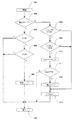
次に図4を用いて振れ状態判別器212の動作について説明する。
なお、図4の処理は所定周期で繰り返し実行される。また処理403〜406は横方向と縦方向は独立に実行される。
処理402により現在静止モードであるか否かの判定をする。
処理402により補正モードと判断されると処理408に移る。
【0029】
処理408ではP、Yの角速度Sが共に所定のしきい値Se より小であるか否かを判定する。ここでP(ピッチ)とは縦方向、Y(ヨー)とは横方向のことである。
処理409では、P、Yの振れ周波数fが共に所定のしきい値fg以下であるか否かを判定する。処理409で共にfg以下と判断されると処理410に移る。
処理409ではメモリCountの値に1加算し保存する。
処理411ではメモリCountの値が所定値chに等しいか否かの判断をする。処理411で等しいと判断されると処理412に移り、等しくないと判断されると処理407で終了する。
【0030】
処理412では、静止モードに移行する。具体的にはHPF210の遮断周波数を静止モード時に設定すべき値に変更する。
処理408、409で条件を満たさなかった時、及び処理412を実行した後に処理413に移行する。
処理413でメモリCount0を保存し、初期化する。
【0031】
処理402により静止モードと判断されると処理403に移る。
処理403では角速度Sが所定のしきい値Saより小であるか否かを判定する。
処理408で大と判断されると処理404に移る。
処理404では、振れ周波数fが所定のしきい値fbより小であるか否かを判定する。
処理404でfb以上と判断されると処理406に移る。
処理406では補正モードに移行する。具体的にはHPF210の遮断周波数を補正モード時に設定すべき値に変更する。
【0032】
本実施の形態は、しきい値fbとfgの値が異なるのが特徴である。これは静止モード中にカメラを指で軽くはじくような振れを与えると、簡単に静止モードから抜けてしまい再び静止モードに入るまでの間、やはり映像がゆらゆらと揺れてしまい、違和感を与えてしまうのを防ぐためである。つまり、しきい値fbをしきい値fgよりも大きな値にすることにより、静止モードに入りやすく、抜けにくくなっている。
【0033】
尚、本実施の形態ではHPF210の遮断周波数を可変としたが、積分器203の特性を可変としても良く、HPFと積分器の両方の特性を可変としても良い。
また、本実施の形態では、CCD111からの切り出しによる電子的振れ補正システムを例に説明したが、レンズ群の内、一部のレンズをシフトさせることにより振れ補正をするシステムや、高屈折率の液体を封入したプリズム(可変頂角プリズム(VAP))の頂角を可変することにより振れ補正をするシステム等の光学的振れ補正手段の場合にも本発明は有効であることは明らかである。
【0034】
【発明の効果】
以上説明したように、本発明によれば、三脚等に固定された静止モード等の補正を制限するモードに入りやすく、抜けにくくすることができるので、このモード中にカメラを指で軽くはじくような振れを与えると、従来のように簡単に静止モードから抜けてしまい、再び静止モードに入るまでの間、映像がゆらゆらと揺れてしまい違和感を与えてしまうのを有効に防ぐことができ、良好な振れ補正を実現することができる。
【図面の簡単な説明】
【図1】本発明による撮像装置の実施の形態を示す構成図である。
【図2】角速度データを振れ補正信号に変換する信号処理を示すブロック図である。
【図3】CCDの撮像面を示す構成図である。
【図4】振れ状態判別器の動作を示すフローチャートである。
【符号の説明】
102 第2のレンズ群(変倍レンズ群)
111 CCD
115 デジタル信号処理部
116 CCD駆動回路
117 マイクロコンピュータ
131、135 角速度センサ
143 記憶媒体
132、136 HPF
301 全イメージサイズ
302〜304 標準イメージサイズ[0001]
BACKGROUND OF THE INVENTION
The present invention relates to an imaging apparatus and a computer-readable storage medium having a shake correction function such as a good camera shake used for a video camera or the like.
[0002]
[Prior art]
In a video camera or the like, a zoom lens with a high magnification is employed, and a zoom ratio of 10 times or more is common in the field of consumer use. When the focal length on the long focus side becomes a large value as the zoom ratio is enlarged, the influence of camera shake due to camera shake or the like on the captured image becomes large on the long focus side. It moves unsightly in the screen. Therefore, in the field of video cameras and the like, a shake correction function that removes the influence of camera shake and the like has been put into practical use.
[0003]
The shake correction function includes at least a shake detection unit that detects a shake component and a shake correction unit that corrects the shake according to the detection result of the detection unit. Among these, as a shake detection means, an electronic detection method for detecting image movement by comparing images between consecutive fields or frames, an angular velocity sensor, an angular acceleration sensor, or the like is used to directly detect camera movement. The method of measuring is mentioned.
[0004]
On the other hand, as the shake correction unit, in addition to the optical shake correction unit that optically adjusts the angle of the photographing optical axis in a direction in which camera shake is removed, a range for actually recording or outputting from the obtained image ( For example, a so-called electronic correction unit that electronically selects a (cutout range) can be used.
[0005]
Now, when shooting with a camera equipped with such a shake correction function fixed to a tripod, the image that should have stopped may be shaken swaying due to noise components from the shake detection means. . For this reason, there is a shake determination means for determining whether the camera is fixed and installed in a stable place such as a tripod. If the determination means determines that the camera is fixed, the vibration correction band is limited, for example, due to noise. A method for removing the shaking of the image has been proposed.
[0006]
In this shake determination means, determination is made from the magnitude and frequency component of the shake signal detected by the shake detection means. First, when normal shake correction occurs, if the shake frequency is lower than the predetermined threshold A and the level of the shake signal is lower than the predetermined threshold B for a predetermined time, the shake correction is band-limited and unnecessary. Cut the movement. This state is called a still mode. Conversely, when the vibration frequency is higher than the predetermined threshold A and the level of the vibration signal is higher than the predetermined threshold B in the still mode, the normal correction is restored.
[0007]
[Problems to be solved by the invention]
However, in the above-mentioned conventional example, if the camera shakes lightly with a finger, for example, while the camera is stationary on a tripod or the like, the camera can easily escape from the still mode, and the video is still displayed until the camera enters the still mode again. However, there was a problem that it sometimes fluctuated and gave a sense of incongruity.
[0008]
Accordingly, an object of the present invention is to prevent inadvertent exit from the stationary mode during the stationary mode.
[0009]
[Means for Solving the Problems]
In the imaging apparatus according to the present invention, an imaging unit that captures a subject image and outputs an image signal, a shake detection unit that detects a shake of the imaging unit, and the image signal based on the shake signal detected by the shake detection unit Correction means for correcting the shake of the image, shake frequency detection means for detecting the frequency of the shake signal, and correction by the shake correction means when the detected shake frequency is smaller than a first threshold, and the shake And a control means for releasing the restriction when the frequency is greater than the second threshold value.
[0010]
In the storage medium according to the present invention, the image signal based on the imaging process for capturing the subject image and outputting the image signal, the shake detection process for detecting the shake of the imaging means, and the shake signal detected by the shake detection process. Correction processing for correcting the shake of the image, shake frequency detection processing for detecting the frequency of the shake signal, and correction by the shake correction processing when the detected shake frequency is smaller than a first threshold, A program for executing a control process for releasing the restriction when the frequency is greater than the second threshold is stored.
[0011]
DETAILED DESCRIPTION OF THE INVENTION
FIG. 1 is a block diagram showing an embodiment of an imaging apparatus according to the present invention.
In FIG. 1,
[0012]
In this embodiment, the
When other actuators are used, a position detection sensor is required as necessary.
[0013]
Reference numeral 111 denotes a CCD (charge coupled device) that converts light into electric charge. Here, the CCD 111 uses a CCD having a larger number of pixels (number of photoelectric conversion elements) than a standard CCD required in a broadcasting system (for example, NTSC system). A
[0014]
In FIG. 3, 301 is an example of the total image size I s of the CCD, and 302, 303, and 304 are examples of the standard image size I N according to the broadcasting system. For example, when valid from the line y1 + 1 below the Δy1 line from the uppermost line, the Δy1 line can be read out at high speed and read out from y1 + 1 at the same timing as when a standard size CCD is used for the vertical synchronization signal.
[0015]
In FIG. 1, reference numeral 112 denotes an analog signal processing unit, which performs a predetermined process on the signal obtained by the CCD 111 to generate an analog image signal. For example, it includes a CDS circuit (correlated double sampling correlated double sampling circuit), an AGC circuit, and the like.
[0016]
Note that the digital image signal stored in the
[0017]
[0018]
An
[0019]
An
[0020]
The
[0021]
The series of operations described above, the total image size I s 301 as shown in FIG. 3, for example 302, 304 as can be cut by shifting the standard image size I N from the center as the deflection due to this result the camera shake or the like It becomes possible to correct.
[0022]
[0023]
Next, signal processing for converting angular velocity data in the
First, angular velocity data is captured by the
A
[0024]
A
Δx = 1 × tan θ (1)
Therefore, the gains according to the respective focal lengths are multiplied here.
[0025]
A zoom gain table 207 associates focal length data and zoom gain and is stored in the ROM area. The
[0026]
A
[0027]
In the stationary mode, the cutoff frequency of the
[0028]
Next, the operation of the
Note that the process of FIG. 4 is repeatedly executed at a predetermined cycle. In addition, the
In
If the correction mode is determined by the
[0029]
In process 408 P, Y angular velocity S together determines whether is smaller than a predetermined threshold value S e. Here, P (pitch) is the vertical direction, and Y (yaw) is the horizontal direction.
In
In
In process 411, it is determined whether or not the value of the memory count is equal to the predetermined value ch. If it is determined in step 411 that they are equal, the process proceeds to step 412, and if it is determined that they are not equal, the process ends in
[0030]
In
When the conditions are not satisfied in the
In
[0031]
If it is determined in the
In
If it is determined in
In
If it is determined in
In
[0032]
The present embodiment is characterized in that the threshold values fb and fg are different. This is because if you shake the camera lightly with your finger while in static mode, the video will shake gently until you get out of static mode again and enter static mode again, giving you a sense of incongruity This is to prevent this. That is, by setting the threshold value fb to a value larger than the threshold value fg, it is easy to enter the stationary mode and it is difficult to escape.
[0033]
In this embodiment, the cutoff frequency of the
In this embodiment, an electronic shake correction system by cutting out from the CCD 111 has been described as an example. However, a system that performs shake correction by shifting some lenses in the lens group, a high refractive index system, or the like. It is apparent that the present invention is also effective in the case of optical shake correction means such as a system that corrects shake by changing the vertical angle of a prism (variable vertical angle prism (VAP)) enclosing a liquid.
[0034]
【The invention's effect】
As described above, according to the present invention, it is easy to enter a mode for restricting correction such as a stationary mode fixed to a tripod or the like, and it is possible to make it difficult to come off. If you give a steady shake, you can effectively prevent the image from shaking out and giving a sense of incongruity until you get out of the still mode as before and enter the still mode again. Smooth shake correction can be realized.
[Brief description of the drawings]
FIG. 1 is a configuration diagram illustrating an embodiment of an imaging apparatus according to the present invention.
FIG. 2 is a block diagram showing signal processing for converting angular velocity data into a shake correction signal.
FIG. 3 is a configuration diagram illustrating an imaging surface of a CCD.
FIG. 4 is a flowchart showing an operation of a shake state discriminator.
[Explanation of symbols]
102 Second lens group (variable magnification lens group)
111 CCD
115 Digital
301 Total image size 302-304 Standard image size
Claims (11)
上記撮像手段の振れを検出する振れ検出手段と、
上記振れ検出手段の検出した振れ信号に基づいて上記画像信号の振れを補正する補正手段と、
上記振れ信号の周波数を検出する振れ周波数検出手段と、
上記検出した振れ周波数が第1のしきい値より小さいとき上記振れ補正手段による補正を制限し、上記振れ周波数が第2のしきい値より大きいとき上記制限を解除する制御手段とを備えた撮像装置。Imaging means for capturing a subject image and outputting an image signal;
Shake detection means for detecting shake of the imaging means;
Correction means for correcting shake of the image signal based on the shake signal detected by the shake detection means;
A vibration frequency detecting means for detecting the frequency of the vibration signal;
An imaging device comprising: control means for limiting correction by the shake correction means when the detected shake frequency is smaller than a first threshold value, and for releasing the restriction when the shake frequency is greater than a second threshold value. apparatus.
撮像手段の振れを検出する振れ検出処理と、
上記振れ検出処理で検出した振れ信号に基づいて上記画像信号の振れを補正する補正処理と、
上記振れ信号の周波数を検出する振れ周波数検出処理と、
上記検出した振れ周波数が第1のしきい値より小さいとき上記振れ補正処理による補正を制限し、上記振れ周波数が第2のしきい値より大きいとき上記制限を解除する制御処理とを実行するためのプログラムを記憶したコンピュータ読み取り可能な記憶媒体。Imaging processing for capturing a subject image and outputting an image signal;
Shake detection processing for detecting shake of the imaging means;
A correction process for correcting the shake of the image signal based on the shake signal detected by the shake detection process;
A shake frequency detection process for detecting the frequency of the shake signal;
A control process for restricting the correction by the shake correction process when the detected shake frequency is smaller than the first threshold and for releasing the restriction when the shake frequency is greater than the second threshold. A computer-readable storage medium storing the program.
Priority Applications (1)
| Application Number | Priority Date | Filing Date | Title |
|---|---|---|---|
| JP07443998A JP4046836B2 (en) | 1998-03-23 | 1998-03-23 | Imaging apparatus and computer-readable storage medium |
Applications Claiming Priority (1)
| Application Number | Priority Date | Filing Date | Title |
|---|---|---|---|
| JP07443998A JP4046836B2 (en) | 1998-03-23 | 1998-03-23 | Imaging apparatus and computer-readable storage medium |
Publications (2)
| Publication Number | Publication Date |
|---|---|
| JPH11275448A JPH11275448A (en) | 1999-10-08 |
| JP4046836B2 true JP4046836B2 (en) | 2008-02-13 |
Family
ID=13547276
Family Applications (1)
| Application Number | Title | Priority Date | Filing Date |
|---|---|---|---|
| JP07443998A Expired - Fee Related JP4046836B2 (en) | 1998-03-23 | 1998-03-23 | Imaging apparatus and computer-readable storage medium |
Country Status (1)
| Country | Link |
|---|---|
| JP (1) | JP4046836B2 (en) |
Cited By (1)
| Publication number | Priority date | Publication date | Assignee | Title |
|---|---|---|---|---|
| US8994835B2 (en) | 2012-05-02 | 2015-03-31 | Canon Kabushiki Kaisha | Exposure control technique for image capturing apparatus and method of controlling same |
Families Citing this family (3)
| Publication number | Priority date | Publication date | Assignee | Title |
|---|---|---|---|---|
| JP4363072B2 (en) * | 2003-03-28 | 2009-11-11 | 株式会社ニコン | Blur correction device |
| JP6351247B2 (en) * | 2013-12-12 | 2018-07-04 | キヤノン株式会社 | Image shake correction apparatus, control method therefor, optical apparatus, and imaging apparatus |
| JP2016090729A (en) * | 2014-10-31 | 2016-05-23 | 旭化成株式会社 | Camera shake correction amount calculation circuit |
-
1998
- 1998-03-23 JP JP07443998A patent/JP4046836B2/en not_active Expired - Fee Related
Cited By (1)
| Publication number | Priority date | Publication date | Assignee | Title |
|---|---|---|---|---|
| US8994835B2 (en) | 2012-05-02 | 2015-03-31 | Canon Kabushiki Kaisha | Exposure control technique for image capturing apparatus and method of controlling same |
Also Published As
| Publication number | Publication date |
|---|---|
| JPH11275448A (en) | 1999-10-08 |
Similar Documents
| Publication | Publication Date | Title |
|---|---|---|
| US7962024B2 (en) | Blur correcting device, blur correcting method, and image pickup apparatus | |
| JP6101074B2 (en) | Optical apparatus, image blur correction apparatus, imaging apparatus, control method therefor, program, and storage medium | |
| JPH09322057A (en) | Imaging device | |
| CN100463500C (en) | Optical Instruments with Image Shake Compensation | |
| JP2004287038A (en) | Imaging device | |
| EP1608156A2 (en) | Auto-focusing apparatus and image pickup apparatus including the same | |
| JP4536855B2 (en) | Anti-vibration device, imaging device, and control method of anti-vibration device | |
| JP4715200B2 (en) | Electronic camera | |
| JP4046836B2 (en) | Imaging apparatus and computer-readable storage medium | |
| JPH11266389A (en) | Imaging device | |
| JP2011023988A (en) | Imaging apparatus | |
| JP2003101866A (en) | Optical device | |
| JPH11284902A (en) | Imaging device, control method thereof, and storage medium | |
| JP4227213B2 (en) | Imaging device | |
| JP5173131B2 (en) | Optical apparatus and focus adjustment method | |
| JPH11266390A (en) | Imaging device | |
| JPH11275431A (en) | Imaging device | |
| JP4011723B2 (en) | Imaging method and apparatus, and storage medium | |
| JP4598901B2 (en) | Imaging device | |
| JP3601414B2 (en) | Video camera autofocus device | |
| JP4195950B2 (en) | Image motion correction device | |
| JPH0641281U (en) | Video camera equipment | |
| JP3697050B2 (en) | Imaging method and apparatus, and storage medium | |
| JPH11298788A (en) | Imaging method and apparatus, and storage medium | |
| JP2603535Y2 (en) | Auto focus device |
Legal Events
| Date | Code | Title | Description |
|---|---|---|---|
| A621 | Written request for application examination |
Free format text: JAPANESE INTERMEDIATE CODE: A621 Effective date: 20050315 |
|
| A977 | Report on retrieval |
Free format text: JAPANESE INTERMEDIATE CODE: A971007 Effective date: 20071101 |
|
| TRDD | Decision of grant or rejection written | ||
| A01 | Written decision to grant a patent or to grant a registration (utility model) |
Free format text: JAPANESE INTERMEDIATE CODE: A01 Effective date: 20071106 |
|
| A61 | First payment of annual fees (during grant procedure) |
Free format text: JAPANESE INTERMEDIATE CODE: A61 Effective date: 20071121 |
|
| FPAY | Renewal fee payment (event date is renewal date of database) |
Free format text: PAYMENT UNTIL: 20101130 Year of fee payment: 3 |
|
| R150 | Certificate of patent or registration of utility model |
Free format text: JAPANESE INTERMEDIATE CODE: R150 |
|
| FPAY | Renewal fee payment (event date is renewal date of database) |
Free format text: PAYMENT UNTIL: 20101130 Year of fee payment: 3 |
|
| FPAY | Renewal fee payment (event date is renewal date of database) |
Free format text: PAYMENT UNTIL: 20111130 Year of fee payment: 4 |
|
| FPAY | Renewal fee payment (event date is renewal date of database) |
Free format text: PAYMENT UNTIL: 20121130 Year of fee payment: 5 |
|
| FPAY | Renewal fee payment (event date is renewal date of database) |
Free format text: PAYMENT UNTIL: 20131130 Year of fee payment: 6 |
|
| LAPS | Cancellation because of no payment of annual fees |