JP4046824B2 - In-cylinder injection type 2-cycle engine - Google Patents
In-cylinder injection type 2-cycle engine Download PDFInfo
- Publication number
- JP4046824B2 JP4046824B2 JP35452397A JP35452397A JP4046824B2 JP 4046824 B2 JP4046824 B2 JP 4046824B2 JP 35452397 A JP35452397 A JP 35452397A JP 35452397 A JP35452397 A JP 35452397A JP 4046824 B2 JP4046824 B2 JP 4046824B2
- Authority
- JP
- Japan
- Prior art keywords
- ring
- cylinder
- fuel
- cycle engine
- piston
- Prior art date
- Legal status (The legal status is an assumption and is not a legal conclusion. Google has not performed a legal analysis and makes no representation as to the accuracy of the status listed.)
- Expired - Fee Related
Links
- 238000002347 injection Methods 0.000 title claims description 24
- 239000007924 injection Substances 0.000 title claims description 24
- 239000000446 fuel Substances 0.000 claims description 42
- 238000002485 combustion reaction Methods 0.000 claims description 20
- 230000002093 peripheral effect Effects 0.000 claims description 10
- 239000003921 oil Substances 0.000 description 21
- 230000036316 preload Effects 0.000 description 7
- 230000002000 scavenging effect Effects 0.000 description 7
- 238000005461 lubrication Methods 0.000 description 6
- 239000000203 mixture Substances 0.000 description 5
- 238000001514 detection method Methods 0.000 description 4
- 230000006835 compression Effects 0.000 description 3
- 238000007906 compression Methods 0.000 description 3
- 238000010586 diagram Methods 0.000 description 3
- 235000014676 Phragmites communis Nutrition 0.000 description 2
- 239000000498 cooling water Substances 0.000 description 2
- 230000000694 effects Effects 0.000 description 2
- 238000005259 measurement Methods 0.000 description 2
- 238000000034 method Methods 0.000 description 2
- 230000007935 neutral effect Effects 0.000 description 2
- 230000001105 regulatory effect Effects 0.000 description 2
- 230000001276 controlling effect Effects 0.000 description 1
- 239000002828 fuel tank Substances 0.000 description 1
- 239000003502 gasoline Substances 0.000 description 1
- 239000007788 liquid Substances 0.000 description 1
- 239000010687 lubricating oil Substances 0.000 description 1
- 238000005192 partition Methods 0.000 description 1
- 230000035485 pulse pressure Effects 0.000 description 1
- 238000011144 upstream manufacturing Methods 0.000 description 1
Images
Classifications
-
- F—MECHANICAL ENGINEERING; LIGHTING; HEATING; WEAPONS; BLASTING
- F16—ENGINEERING ELEMENTS AND UNITS; GENERAL MEASURES FOR PRODUCING AND MAINTAINING EFFECTIVE FUNCTIONING OF MACHINES OR INSTALLATIONS; THERMAL INSULATION IN GENERAL
- F16J—PISTONS; CYLINDERS; SEALINGS
- F16J9/00—Piston-rings, e.g. non-metallic piston-rings, seats therefor; Ring sealings of similar construction
- F16J9/12—Details
- F16J9/20—Rings with special cross-section; Oil-scraping rings
- F16J9/206—One-piece oil-scraping rings
-
- F—MECHANICAL ENGINEERING; LIGHTING; HEATING; WEAPONS; BLASTING
- F02—COMBUSTION ENGINES; HOT-GAS OR COMBUSTION-PRODUCT ENGINE PLANTS
- F02B—INTERNAL-COMBUSTION PISTON ENGINES; COMBUSTION ENGINES IN GENERAL
- F02B23/00—Other engines characterised by special shape or construction of combustion chambers to improve operation
- F02B23/08—Other engines characterised by special shape or construction of combustion chambers to improve operation with positive ignition
- F02B23/10—Other engines characterised by special shape or construction of combustion chambers to improve operation with positive ignition with separate admission of air and fuel into cylinder
- F02B23/101—Other engines characterised by special shape or construction of combustion chambers to improve operation with positive ignition with separate admission of air and fuel into cylinder the injector being placed on or close to the cylinder centre axis, e.g. with mixture formation using spray guided concepts
Landscapes
- Engineering & Computer Science (AREA)
- General Engineering & Computer Science (AREA)
- Mechanical Engineering (AREA)
- Pistons, Piston Rings, And Cylinders (AREA)
- Combustion Methods Of Internal-Combustion Engines (AREA)
Description
【0001】
【発明の属する技術分野】
本発明は、外周にトップリングとセカンドリングを外嵌して成るピストンが摺動するシリンダ内に燃料を直接噴射する筒内噴射式2サイクルエンジンに関する。
【0002】
【従来の技術】
燃料を吸気管内に噴射する旧来の2サイクルエンジンにおいては、オイルが燃料と共にクランク室内に導入されるため、オイルが燃料(ガソリン)で希釈された状態で各部に十分行き渡って各摺動部の潤滑に供される。
【0003】
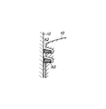
一方、燃料をシリンダ内に直接噴射する筒内噴射式2サイクルエンジンにおいては、燃焼室以外は生オイルと空気による潤滑となるため、オイルの流動性不足による潤滑不良が発生し易く、図7に示すようにクランク室側からの粘度の高いオイルがピストン113のセカンドリング163によって遮られてトップリング162側へ十分供給されず、トップリング162の摩耗やシリンダ112のスカッフィングが生じ易いという問題があった。
【0004】
【発明が解決しようとする課題】
そこで、4サイクルエンジンと同様に2サイクルエンジンにオイルパンを設けてクランク室内を積極的に潤滑する提案がなされているが、これによればシステムが複雑化及び大型化し、4サイクルエンジンと同様に高コスト化を免れないという問題が発生する。
【0005】
又、オイルポンプによってオイルを吸気管内に供給する方式も提案されているが、この方式によっても低・中速域においてオイルの流動性不足による潤滑不良が発生し、ピストンのトップリングの摩耗やスカッフィングが生じ易いという問題があった。
【0006】
本発明は上記問題に鑑みてなされたもので、その目的とする処は、簡単な構成でピストンのトップリングの摩耗やスカッフィングの発生を効果的に防ぐことができる筒内噴射式2サイクルエンジンを提供することにある。
【0007】
【課題を解決するための手段】
上記目的を達成するため、本発明は、外周に燃焼室側から順にトップリングとセカンドリングを外嵌して成るピストンが摺動するシリンダ内に燃料を直接噴射する筒内噴射式2サイクルエンジンにおいて、リング溝に嵌合された前記セカンドリングを、その前記燃焼室側と反対側の端部が前記燃焼室側の端部よりも前記セカンドリングの径方向内側に位置する逆テーパ面を形成する逆テーパリングで構成し、前記逆テーパ面を、その前記燃焼室側と反対側の端部が、前記リング溝の前記ピストンの外周側の端部よりも内側に位置するよう形成したことを特徴とする。
【0008】
従って、本発明によれば、ピストンのセカンドリングを逆テーパリングで構成したため、ピストンの下降行程時においてはシリンダの内周面に付着したオイルを逆テーパリングによる楔作用によってトップリング側に十分供給することができ、ピストンの上昇行程時においてはシリンダの内周面に付着したオイルを逆テーパリングの外周エッジ部で掻き上げてトップリング側に十分供給することができ、この結果、トップリング周辺の潤滑が飛躍的に向上し、簡単な構成でピストンのトップリングの摩耗やスカッフィングの発生を効果的に防ぐことができる。
【0009】
【発明の実施の形態】
以下に本発明の実施の形態を添付図面に基づいて説明する。
【0010】
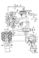
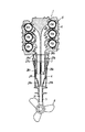
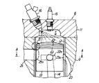
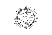
図1は本発明に係る筒内噴射式2サイクルエンジンを備える船外機の基本構成を示す模式的構成図、図2は同船外機の縦断面図、図3は本発明に係る筒内噴射式2サイクルエンジン要部の断面図、図4は図3のA−A線断面図、図5は図3のB部拡大断面図である。
【0011】
図1に示す船外機1は、トップカウル2、エキゾーストガイド3、アッパーケース4及びロアーケース5で構成されるハウジングを有しており、トップカウル2内には本発明に係る筒内噴射式2サイクルエンジン6が収納されている。尚、2サイクルエンジン6の上下方向に配されたクランク軸7にはエキゾーストガイド3とアッパーケース4及びロアーケース5内に縦設された不図示のドライブ軸が連結されており、該ドライブ軸の下端は前後進切換機構を介してプロペラ軸(共に不図示)が連結されている。そして、プロペラ軸のロアーケース5外へ延出する後端部にはプロペラ8が取り付けられている。
【0012】
ところで、本発明に係る前記筒内噴射式2サイクルエンジン6はV型6気筒エンジンであり、図2に示すように、シリンダボディ9には6つの気筒10a〜10fが平面視V形を成して横置き状態で上下方向に並設されており、シリンダボディ9の端部にはシリンダヘッド11が被着されている(図1及び図3参照)。
【0013】
而して、図3に示すように、シリンダボディ9に形成された各気筒10a〜10fのシリンダ12にはピストン13が摺動自在に嵌装されており、該ピストン13はコンロッド14を介して前記クランク軸7(図1参照)に連結されている。
【0014】
又、図3に示すように、前記シリンダヘッド11の各気筒10a〜10fには燃焼室Sがそれぞれ形成されており、シリンダヘッド11にはその電極部が燃焼室Sに臨む点火プラグ15と燃料噴射口が燃焼室Sに開口するインジェクタ16が各気筒10a〜10f毎にそれぞれ螺着されている。
【0015】
一方、図1に示すように、シリンダボディ9の側端部にはクランクケース17が取り付けられており、このクランクケース17内のクランク室には吸気マニホールドの吸気管18が接続されており、この吸気管18のクランク室への接続部には逆流防止用のリード弁19が設けられ、このリード弁19の上流側には吸気料を制御するためのスロットル弁20が配設されている。そして、吸気管18内のスロットル弁20の下流側にはオイルポンプ21によって潤滑用のオイルが噴射される。
【0016】
ところで、図3及び図4に示すように、シリンダボディ9にはクランク室と各気筒10a〜10fのシリンダ12内とを連通させる掃気通路22,23,24と排気通路25が各気筒10a〜10fについてそれぞれ形成されており、掃気通路22,23,24は掃気ポート22a,23a,24aとしてシリンダ12内に開口しており、排気通路25は排気ポート25aとしてシリンダ12内に開口している。
【0017】
上記各排気通路25は、図2に示すように、左右の各バンク毎に集合されて排気通路26a,26bを形成しており、これらの排気通路26a,26bは前記エキゾーストガイド3に形成された排気通路27a,27bを介して前記アッパーケース4内に収納された排気管28a,28bにそれぞれ接続されている。
【0018】
上記排気管28a,28bは同じくアッパーケース4内に収納されたマフラー29内の隔壁30によって左右に区画された膨張室29a,29bにそれぞれ開口している。そして、マフラー29は前記ロアーケース5に形成された排気通路31に接続されている。
【0019】
次に、燃料供給系を図1に基づいて説明する。
【0020】
図1に示す主燃料タンク32内の燃料は、第1の低圧燃料ポンプ33によってフィルタ34を経て第2の低圧燃料ポンプ35に送られる。この第2の低圧燃料ポンプ35はエンジン6のクランク室のパルス圧によって駆動されるダイヤフラム式ポンプであって、これは燃料を気液分離装置であるベーパーセパレータタンク36に送る。
【0021】
上記ベーパーセパレータタンク36内には電動モータによって駆動される燃料予圧ポンプ37が配設されており、燃料はこの燃料予圧ポンプ37によって加圧されて予圧配管38を通って高圧燃料ポンプ39に送られる。ここで、高圧燃料ポンプ39の吐出側は各気筒10a〜10fに沿って縦方向に配設された燃料供給レール40に接続されるとともに、燃料戻し配管41を介してベーパーセパレータタンク36に接続されている。尚、燃料戻し配管41の途中には高圧調整弁42及び燃料冷却器43が設けられている。又、予圧配管38とベーパーセパレータタンク36との間には予圧調整弁44が設けられている。
【0022】
而して、ベーパーセパレータタンク36内の燃料は燃料予圧ポンプ37によって例えば3〜10kg/cm2 程度に予圧され、予圧された燃料は高圧燃料ポンプ39によって50〜100kg/cm2 程度に加圧されて燃料供給レール40から各インンジェクタ16に供給され、各インジェクタ16によって適当なタイミングで各気筒10a〜10fのシリンダ12内に直接噴射される。尚、噴射されないで余った余剰燃料は高圧調整弁42及び燃料冷却器43を通過して燃料戻し配管41からベーパーセパレータタンク36に戻される。
【0023】
而して、前記点火プラグ15、インジェクタ16、オイルポンプ21及び燃料予圧ポンプ37はエンジン制御装置(ECU)45によって制御されるが、エンジン制御装置45にはエンジン6の運転状態や船外機1或は船体の状態を示す各種センサからの検出信号が入力される。
【0024】
即ち、エンジン制御装置45には、クランク軸7の回転数を検出する回転センサ46、特定気筒を判別する気筒判別センサ47、吸気管18内の温度を検出する吸気温センサ48、シリンダボディ9の温度を検出するエンジン温度センサ49、各気筒10a〜10fの背圧を検出する背圧センサ50、スロットル弁20の開度を検出するスロットル開度センサ51、冷却水の温度を検出する冷却水温度センサ52、エンジン6の振動を検出するエンジン振動センサ53、エンジン6のマウント高さを検出するエンジンマウント高さ検出センサ54、船外機1のニュートラル状態を検出するニュートラルセンサ55、船外機1の上下回動位置を検出するトリム角検出センサ56、船速を検出する船速センサ57、船体の姿勢を検出する姿勢センサ58、大気圧を検出する大気圧センサ59、混合気の空燃比を検出する空燃比センサ60及び燃料圧を検出する圧力センサ61からの検出信号がそれぞれ入力される。
【0025】
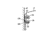
ところで、図5に詳細に示すように、ピストン13の外周には2つのリング溝13a,13bが全周に亘って2段に形成されており、燃焼室S側(図5の上側)のリング溝13aにはトップリング62が嵌合され、他方のリング溝13bにはセカンドリング63が嵌合されている。
【0026】
而して、上記トップリング62には従来の2サイクルエンジン同様のバレルフェース形状の外周面を有するリングが使用され、セカンドリング63には、その外周面が燃焼室S方向(図5の上方)に向かって幅広となる逆テーパ面63aを形成する逆テーパリングが使用されている。
【0027】
次に、本発明に係る筒内噴射2サイクルエンジン6の作用を説明する。
【0028】
筒内噴射式2サイクルエンジン6が始動され、各気筒10a〜10fにおいてピストン13がシリンダ12内を下死点(BDC)から上死点(TDC)に向かって摺動する圧縮行程においては、クランク室内に発生する負圧に引かれて空気(新気)が吸気管18内に吸引され、この空気はスロットル弁20を通過した後、オイルポンプ21によって吸気管18内に噴射されるオイルと共にリード弁19を通過してクランク室内に流入する。そして、クランク室内に流入した空気とオイルはその後の膨張行程において上死点から下死点に向かって摺動するピストン13によって一次圧縮される。尚、このとき、クランク室内のオイルは各部に供給されて各摺動部の潤滑に供されるが、図5に示すように、シリンダ12の内周面に付着したオイルは逆テーパリングで構成されるセカンドリング63による楔作用(呼び込み作用)によってトップリング62側に十分供給される。
【0029】
上述のようにピストン13が下死点に向かって摺動して先ず排気ポート25aが開き始めると、燃焼室Sでの混合気の燃焼によって発生した高温・高圧の排気ガスが排気ポート25aから排気通路25へと排出される排気ブローダウンが開始され、その後、掃気ポート22a〜24aが開くと、前のサイクルで一次圧縮されたクランク室内の空気が図4に矢印にて示すようにオイルと共に掃気通路22〜24を通って掃気ポート22a〜24aからシリンダ12内に流入し、シリンダ12内の排気ガスを排気ポート25aから排気通路25へと押し出す掃気作用を行う。
【0030】
そして、ピストン13が下死点を過ぎて上死点側に向かって摺動する圧縮行程に移行すると、シリンダ12の内周面に付着したオイルを逆テーパリングで構成されたセカンドリング63の外周エッジ部63bで掻き上げられてトップリング62側に十分供給される。
【0031】
上記圧縮行程において、ピストン13によって掃気ポート22a〜24aが閉じられ、続いて排気ポート25aが閉じられると、シリンダ12内の空気は圧縮され、この空気にインジェクタ16から適当なタイミングで適量の燃料が噴射されて所要の空燃比の混合気が形成される。そして、この混合気はピストン13によって更に圧縮され、ピストン13が上死点近傍に達した時点或は上死点を過ぎた直後の適当なタイミングで点火プラグ15によって着火されて燃焼せしめられる。
【0032】
而して、燃焼室Sでの混合気の燃焼によって発生した高温・高圧の排気ガスは前述のように排気行程において排気ポート25aを通って排気通路25へと排出される。
【0033】
以後、上記と同様の作用が繰り返されて当該2サイクルエンジン6が連続して運転される。
【0034】
以上のように、本実施の形態に係る筒内噴射式2サイクルエンジン6においては、ピストン13のセカンドリング63を逆テーパリングで構成したため、ピストン6の下降行程時においてはシリンダ12の内周面に付着したオイルを逆テーパリング63による楔作用によってトップリング62側に十分供給することができ、ピストン13の上昇行程時においてはシリンダ12の内周面に付着したオイルを逆テーパリング63の外周エッジ部63bで掻き上げてトップリング62側に十分供給することができる。この結果、トップリング62周辺の潤滑が飛躍的に向上し、簡単な構成でピストン13のトップリング62の摩耗やスカッフィングの発生を効果的に防ぐことができる。
【0035】
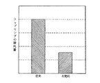
ここで、トップリング62の摩耗量の実測結果を従来との比較において図6に示すが、本発明によればトップリング62の摩耗量を従来よりも小さく抑えることができることが分かる。
【0036】
尚、以上は特に船外機に搭載された筒内噴射式2サイクルエンジンに本発明を適用した例について述べたが、本発明は他の任意の筒内噴射2サイクルエンジンに対しても同様に適用することもができる。
【0037】
【発明の効果】
以上の説明で明らかなように、本発明によれば、外周にトップリングとセカクドリングを外嵌して成るピストンが摺動するシリンダ内に燃料を直接噴射する筒内噴射式2サイクルエンジンにおいて、前記セカンドリングをその外周面が燃焼室側に向かって幅広となる逆テーパ面を形成する逆テーパリングで構成したため、簡単な構成でピストンのトップリングの摩耗やスカッフィングの発生を効果的に防ぐことができるという効果が得られる。
【図面の簡単な説明】
【図1】本発明に係る筒内噴射式2サイクルエンジンを備える船外機の基本構成を示す模式的構成図である。
【図2】本発明に係る筒内噴射式2サイクルエンジンを備える船外機の縦断面図である。
【図3】本発明に係る筒内噴射式2サイクルエンジン要部の断面図である。
【図4】図3のA−A線断面図である。
【図5】図3のB部拡大断面図である。
【図6】本発明に係る筒内噴射式2サイクルエンジンのトップリングの摩耗量の実測結果を従来と比較して示す図である。
【図7】従来の筒内噴射式2サイクルエンジンのピストンリング部分の断面図である。
【符号の説明】
6 筒内噴射式2サイクルエンジン
12 シリンダ
13 ピストン
62 トップリング
63 セカンドリング(逆テーパリング)
63a 逆テーパ面
S 燃焼室[0001]
BACKGROUND OF THE INVENTION
The present invention relates to an in-cylinder injection type two-cycle engine in which fuel is directly injected into a cylinder in which a piston formed by externally fitting a top ring and a second ring on the outer periphery slides.
[0002]
[Prior art]
In a conventional two-cycle engine that injects fuel into the intake pipe, oil is introduced into the crank chamber together with the fuel. Therefore, the oil is diluted with the fuel (gasoline) and is sufficiently distributed to each part to lubricate each sliding part. To be served.
[0003]
On the other hand, in a cylinder injection type two-cycle engine in which fuel is directly injected into the cylinder, lubrication is performed with raw oil and air except for the combustion chamber, and therefore, lubrication failure due to insufficient fluidity of the oil is likely to occur. As shown in the figure, oil with high viscosity from the crank chamber side is blocked by the
[0004]
[Problems to be solved by the invention]
Therefore, as in the case of a 4-cycle engine, a proposal has been made to provide an oil pan in a 2-cycle engine and actively lubricate the crankcase. However, this increases the complexity and size of the system, as in the case of a 4-cycle engine. There arises a problem that high costs cannot be avoided.
[0005]
In addition, a method of supplying oil into the intake pipe by an oil pump has also been proposed, but this method also causes poor lubrication due to insufficient fluidity of oil at low and medium speed ranges, and wear and scuffing of the piston top ring. There was a problem that it was easy to occur.
[0006]
The present invention has been made in view of the above problems, and the object of the present invention is to provide an in-cylinder injection type two-cycle engine that can effectively prevent the wear of the top ring of the piston and the occurrence of scuffing with a simple configuration. It is to provide.
[0007]
[Means for Solving the Problems]
In order to achieve the above object, the present invention provides an in-cylinder injection type two-cycle engine in which fuel is directly injected into a cylinder in which a piston, in which a top ring and a second ring are fitted in order from the combustion chamber side on the outer periphery, slides. The second ring fitted in the ring groove is formed with a reverse taper surface in which the end opposite to the combustion chamber side is positioned radially inward of the second ring from the end on the combustion chamber side. A reverse taper ring is used, and the reverse taper surface is formed such that the end opposite to the combustion chamber side is positioned inside the end of the ring groove on the outer peripheral side of the piston. And
[0008]
Therefore, according to the present invention, since the second ring of the piston is constituted by the reverse taper ring, the oil adhering to the inner peripheral surface of the cylinder is sufficiently supplied to the top ring side by the wedge action by the reverse taper ring during the downward stroke of the piston. During the upward stroke of the piston, the oil adhering to the inner peripheral surface of the cylinder can be scraped up at the outer peripheral edge of the reverse taper ring and supplied sufficiently to the top ring side. The lubrication of the piston is dramatically improved, and the piston top ring wear and scuffing can be effectively prevented with a simple configuration.
[0009]
DETAILED DESCRIPTION OF THE INVENTION
Embodiments of the present invention will be described below with reference to the accompanying drawings.
[0010]
FIG. 1 is a schematic configuration diagram showing a basic configuration of an outboard motor equipped with an in-cylinder injection two-cycle engine according to the present invention, FIG. 2 is a longitudinal sectional view of the outboard motor, and FIG. 3 is an in-cylinder injection according to the present invention. 4 is a cross-sectional view of the main part of the two-cycle engine, FIG. 4 is a cross-sectional view taken along line AA of FIG. 3, and FIG. 5 is an enlarged cross-sectional view of a B part of FIG.
[0011]
An
[0012]
By the way, the in-cylinder injection type two-
[0013]
Thus, as shown in FIG. 3, a
[0014]
Further, as shown in FIG. 3, a combustion chamber S is formed in each of the
[0015]
On the other hand, as shown in FIG. 1, a crankcase 17 is attached to the side end of the cylinder body 9, and an intake pipe 18 of an intake manifold is connected to a crank chamber in the crankcase 17. A
[0016]
As shown in FIGS. 3 and 4, the cylinder body 9 includes
[0017]
As shown in FIG. 2, the
[0018]
The
[0019]
Next, the fuel supply system will be described with reference to FIG.
[0020]
The fuel in the
[0021]
A
[0022]
Thus, the fuel in the
[0023]
Thus, the
[0024]
That is, the
[0025]
Incidentally, as shown in detail in FIG. 5, two ring grooves 13a and 13b are formed on the outer periphery of the
[0026]
Thus, a ring having a barrel face-shaped outer peripheral surface similar to the conventional two-cycle engine is used for the top ring 62, and the outer surface of the
[0027]
Next, the operation of the in-cylinder injection two-
[0028]
In the compression stroke in which the in-cylinder injection type two-
[0029]
As described above, when the
[0030]
Then, when the
[0031]
In the compression stroke, when the scavenging
[0032]
Thus, the high-temperature and high-pressure exhaust gas generated by the combustion of the air-fuel mixture in the combustion chamber S is discharged to the
[0033]
Thereafter, the same operation as described above is repeated, and the two-
[0034]
As described above, in the in-cylinder injection type two-
[0035]
Here, an actual measurement result of the wear amount of the top ring 62 is shown in FIG. 6 in comparison with the prior art, but it can be seen that according to the present invention, the wear amount of the top ring 62 can be suppressed smaller than the conventional one.
[0036]
Although the example in which the present invention is applied to the in-cylinder injection two-cycle engine mounted on the outboard motor has been described above, the present invention is similarly applied to other arbitrary in-cylinder injection two-cycle engines. It can also be applied.
[0037]
【The invention's effect】
As is apparent from the above description, according to the present invention, in the in-cylinder injection type two-cycle engine in which fuel is directly injected into a cylinder in which a piston formed by externally fitting a top ring and a second ring is slid, Since the second ring is composed of a reverse taper surface that forms a reverse taper surface whose outer peripheral surface becomes wider toward the combustion chamber, it is possible to effectively prevent piston top ring wear and scuffing with a simple structure. The effect that it can be obtained.
[Brief description of the drawings]
FIG. 1 is a schematic configuration diagram showing a basic configuration of an outboard motor equipped with an in-cylinder injection type two-cycle engine according to the present invention.
FIG. 2 is a longitudinal sectional view of an outboard motor equipped with an in-cylinder injection type two-cycle engine according to the present invention.
FIG. 3 is a cross-sectional view of a main part of a direct injection two-cycle engine according to the present invention.
4 is a cross-sectional view taken along line AA in FIG.
FIG. 5 is an enlarged cross-sectional view of a portion B in FIG.
FIG. 6 is a diagram showing an actual measurement result of the amount of wear of the top ring of the in-cylinder injection type two-cycle engine according to the present invention in comparison with the prior art.
FIG. 7 is a cross-sectional view of a piston ring portion of a conventional in-cylinder injection two-cycle engine.
[Explanation of symbols]
6 In-cylinder injection type 2-cycle engine 12
63a Reverse taper surface S Combustion chamber
Claims (1)
Priority Applications (2)
| Application Number | Priority Date | Filing Date | Title |
|---|---|---|---|
| JP35452397A JP4046824B2 (en) | 1997-12-24 | 1997-12-24 | In-cylinder injection type 2-cycle engine |
| US09/220,517 US20010040346A1 (en) | 1997-12-24 | 1998-12-24 | Piston ring assembly |
Applications Claiming Priority (1)
| Application Number | Priority Date | Filing Date | Title |
|---|---|---|---|
| JP35452397A JP4046824B2 (en) | 1997-12-24 | 1997-12-24 | In-cylinder injection type 2-cycle engine |
Publications (2)
| Publication Number | Publication Date |
|---|---|
| JPH11182338A JPH11182338A (en) | 1999-07-06 |
| JP4046824B2 true JP4046824B2 (en) | 2008-02-13 |
Family
ID=18438136
Family Applications (1)
| Application Number | Title | Priority Date | Filing Date |
|---|---|---|---|
| JP35452397A Expired - Fee Related JP4046824B2 (en) | 1997-12-24 | 1997-12-24 | In-cylinder injection type 2-cycle engine |
Country Status (2)
| Country | Link |
|---|---|
| US (1) | US20010040346A1 (en) |
| JP (1) | JP4046824B2 (en) |
Families Citing this family (4)
| Publication number | Priority date | Publication date | Assignee | Title |
|---|---|---|---|---|
| US7438039B2 (en) | 2004-02-06 | 2008-10-21 | Electro-Motive Diesel, Inc. | Large-bore, medium-speed diesel engine having piston crown bowl with acute re-entrant angle |
| DE102013219052A1 (en) * | 2013-09-23 | 2015-04-09 | Mahle International Gmbh | Piston with piston ring groove, in particular compression groove |
| CN111188692A (en) * | 2018-11-15 | 2020-05-22 | 日立汽车系统(苏州)有限公司 | Device to improve oil dilution |
| JP7458199B2 (en) * | 2019-09-02 | 2024-03-29 | 株式会社東芝 | semiconductor equipment |
-
1997
- 1997-12-24 JP JP35452397A patent/JP4046824B2/en not_active Expired - Fee Related
-
1998
- 1998-12-24 US US09/220,517 patent/US20010040346A1/en not_active Abandoned
Also Published As
| Publication number | Publication date |
|---|---|
| US20010040346A1 (en) | 2001-11-15 |
| JPH11182338A (en) | 1999-07-06 |
Similar Documents
| Publication | Publication Date | Title |
|---|---|---|
| US5584281A (en) | Engine control system | |
| US6116228A (en) | Control for engine | |
| US6135095A (en) | Engine control | |
| US6148777A (en) | Control for direct injected two cycle engine | |
| JPH11280540A (en) | Cylinder fuel injection engine | |
| US6058907A (en) | Control for direct injected two cycle engine | |
| US5713325A (en) | Engine injection control | |
| US6067957A (en) | Transient engine control | |
| EP0831217A2 (en) | Multi-cylinder internal combustion engine | |
| JPH11182679A (en) | Internal combustion engine | |
| US6067956A (en) | Knock control for engine | |
| US6357417B2 (en) | Start up control for engine | |
| US6119453A (en) | Feed back control utilizing catalyst | |
| US5522370A (en) | Multi-cylinder engine control system | |
| US6367450B1 (en) | Fuel injection control system for outboard motor | |
| JPH0357876A (en) | Cylinder injection two-cycle engine | |
| US4383503A (en) | Combustion chamber scavenging system | |
| JP4046824B2 (en) | In-cylinder injection type 2-cycle engine | |
| US6065442A (en) | Start-up strategy for engine feed back control | |
| US20020144669A1 (en) | Air induction system for multi-cylinder engine | |
| US5666935A (en) | Fuel injection control for engine | |
| JP4194007B2 (en) | 2-cycle engine | |
| US6065445A (en) | Engine feedback control | |
| US6227165B1 (en) | Engine control strategy and system | |
| JP4334720B2 (en) | In-cylinder injection type 2-cycle engine |
Legal Events
| Date | Code | Title | Description |
|---|---|---|---|
| A621 | Written request for application examination |
Free format text: JAPANESE INTERMEDIATE CODE: A621 Effective date: 20041101 |
|
| RD04 | Notification of resignation of power of attorney |
Free format text: JAPANESE INTERMEDIATE CODE: A7424 Effective date: 20060328 |
|
| RD02 | Notification of acceptance of power of attorney |
Free format text: JAPANESE INTERMEDIATE CODE: A7422 Effective date: 20060413 |
|
| A131 | Notification of reasons for refusal |
Free format text: JAPANESE INTERMEDIATE CODE: A131 Effective date: 20070522 |
|
| A521 | Request for written amendment filed |
Free format text: JAPANESE INTERMEDIATE CODE: A523 Effective date: 20070718 |
|
| A131 | Notification of reasons for refusal |
Free format text: JAPANESE INTERMEDIATE CODE: A131 Effective date: 20071023 |
|
| A521 | Request for written amendment filed |
Free format text: JAPANESE INTERMEDIATE CODE: A523 Effective date: 20071031 |
|
| TRDD | Decision of grant or rejection written | ||
| A01 | Written decision to grant a patent or to grant a registration (utility model) |
Free format text: JAPANESE INTERMEDIATE CODE: A01 Effective date: 20071120 |
|
| A61 | First payment of annual fees (during grant procedure) |
Free format text: JAPANESE INTERMEDIATE CODE: A61 Effective date: 20071121 |
|
| FPAY | Renewal fee payment (event date is renewal date of database) |
Free format text: PAYMENT UNTIL: 20101130 Year of fee payment: 3 |
|
| R150 | Certificate of patent or registration of utility model |
Free format text: JAPANESE INTERMEDIATE CODE: R150 |
|
| FPAY | Renewal fee payment (event date is renewal date of database) |
Free format text: PAYMENT UNTIL: 20101130 Year of fee payment: 3 |
|
| S111 | Request for change of ownership or part of ownership |
Free format text: JAPANESE INTERMEDIATE CODE: R313111 |
|
| FPAY | Renewal fee payment (event date is renewal date of database) |
Free format text: PAYMENT UNTIL: 20101130 Year of fee payment: 3 |
|
| R371 | Transfer withdrawn |
Free format text: JAPANESE INTERMEDIATE CODE: R371 |
|
| S111 | Request for change of ownership or part of ownership |
Free format text: JAPANESE INTERMEDIATE CODE: R313111 |
|
| FPAY | Renewal fee payment (event date is renewal date of database) |
Free format text: PAYMENT UNTIL: 20101130 Year of fee payment: 3 |
|
| R350 | Written notification of registration of transfer |
Free format text: JAPANESE INTERMEDIATE CODE: R350 |
|
| FPAY | Renewal fee payment (event date is renewal date of database) |
Free format text: PAYMENT UNTIL: 20101130 Year of fee payment: 3 |
|
| FPAY | Renewal fee payment (event date is renewal date of database) |
Free format text: PAYMENT UNTIL: 20111130 Year of fee payment: 4 |
|
| LAPS | Cancellation because of no payment of annual fees |