JP4046823B2 - Blown floor multi-stage display tray - Google Patents
Blown floor multi-stage display tray Download PDFInfo
- Publication number
- JP4046823B2 JP4046823B2 JP34923697A JP34923697A JP4046823B2 JP 4046823 B2 JP4046823 B2 JP 4046823B2 JP 34923697 A JP34923697 A JP 34923697A JP 34923697 A JP34923697 A JP 34923697A JP 4046823 B2 JP4046823 B2 JP 4046823B2
- Authority
- JP
- Japan
- Prior art keywords
- floor
- blow
- wall
- center
- blown
- Prior art date
- Legal status (The legal status is an assumption and is not a legal conclusion. Google has not performed a legal analysis and makes no representation as to the accuracy of the status listed.)
- Expired - Fee Related
Links
Images
Landscapes
- Display Racks (AREA)
Description
【0001】
【発明の属する技術分野】
本発明は、陳列トレーに関する。
【0002】
【従来の技術】
従来の陳列トレーは一段の物が多く、複段に成った物は下の段の物を取り出し易くする為に、上下段の間隔を広くしていた。
【0003】
【発明が解決しようとする課題】
一段の物は上の空間を有効利用できず、複段の物で上下段の間隔を広くした物では、間隔を広くする分だけトレーの側壁を縦長にする必要があるので、トレー本体が大きくなる他、縦長に成る事によって重心が高くなるので、安定性が悪くなる、という欠点が生じる。本発明では、上下段の間隔を狭くしても下の段の物を出し入れし易くできる、という課題の解決を目的とする。
【0004】
【課題を解決するための手段】
段どうしの間を広くする目的は、下の段に置かれた商品を取り出す為に、指を入れる隙間の確保であり、上の段の中央を前後に貫いた溝で吹き抜け部を設けて吹き抜け床を形成する事で、吹き抜け部が指入れの隙間と成るので、上下段の間を狭める事ができる。
【0005】
【発明の実施の形態】
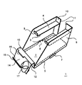
本発明物は、透明樹脂或いは半透明樹脂を素材に用いて、インジェクション、つまり射出成形によって製造する。要部透視斜視図の図1に於いて、トレー本体1は、少なくても二段設け、最下段の段を底壁2とし、上の段を床とし、床の中央を前後に貫く溝で吹き抜け部3を設け、この吹き抜け部3を有する床を吹き抜け床4とし、吹き抜け床4の正面端には塞き止め壁9を有しており、背面端には背壁10を有して塞き止めており、背壁10の中央も吹き抜け部3と同じ幅で縦に切り除かれて背除部11を有している事が望ましく、吹き抜け床4は側壁6と背壁10との上部領域に水平に取り付けられる事が望ましく、底壁2は前後に長い矩形を成しており、底壁2の周囲から下方にスカート枠5を垂らし、スカート枠5の両側の縁で、一方の下縁の中央から外側へ向けて水平に壁の厚み分だけ突出して折り上げられたL字形状でL凸部7を取り付け、他方の下縁の中央を壁の厚み分だけ窪ませて受け凹部8を形成し、一方の本体1のL凸部7に、他方の本体1の受け凹部8を嵌め込む事によって本体1どうしは横に連結され、底壁2の正面縁から正面壁12を垂直に折り起こし、天縁から正面方向へ水平に折り出して天額縁帯13を延設し、正面縁から適宜な角度を有して表示壁14を延設し、表示壁14の一方の側の天地からL字状のフック縁15を突出させてカードホルダー16を形成し、他方の側に有底の円柱形状でサンプル入れ17を形成しても良い。
【0006】
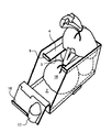
商品を陳列した状態で示した要部透視斜視図の図2に於いて、下段の商品18は底壁2の上に置き、上段の商品18は吹き抜け床4上に置き、商品18の形状は箱形状であっても良いが、頂部の基部を紐で束ねて束ね部19を形成した巾着状の物である方が都合が良く、下段の商品18の束ね部19は、吹き抜け部3から食み出しており、この食み出した束ね部19を摘み上げる事によって、下段の商品18を容易に出し入れでき、カードホルダー16には値札や商品名などを表示し、サンプル入れ17には、商品18が香料であった場合、香りのサンプルを入れた瓶を収納しておく。
【0007】
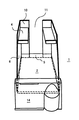
真っ正面の斜め上から示した要部透視斜視図の図3に於いて、本体1は三つのパーツから組み立てられており、スカート枠5と底壁2と表示壁14まで一体化した物を基礎にし、底壁2の両背角領域と側縁の中央と正面領域とに差込溝を設け、それらの溝へ、側壁と背壁と吹き抜け床とが一体化したパーツを差し込む事で固定し、背除部11を設ける事で側壁6のパーツは平たい形状に近づき、食み出し箇所が少ないので輸送時に割れる恐れが軽減される。
【0008】
【発明の効果】
上段の床を吹き抜け床にした事によって、下段に収納された商品を出し入れする場合、吹き抜け部から指を入れるか又は商品の頂部の食み出た箇所を摘まんで正面の開口部から取り出す事ができ、L凸部と受け凹部を設けた事で、複数のトレー本体を横に連結する事ができる。
【図面の簡単な説明】
【図1】要部透視斜視図
【図2】商品を陳列した状態で示した要部透視斜視図
【図3】真っ正面の斜め上から示した要部透視斜視図
【符号の説明】
1 本体
2 底壁
3 吹き抜け部
4 吹き抜け床
5 スカート枠
6 側壁
7 L凸部
8 受け凹部[0001]
BACKGROUND OF THE INVENTION
The present invention relates to a display tray.
[0002]
[Prior art]
Conventional display trays have many single-tiered items, and in order to make it easier to pick out the lower-tiered items, the upper and lower intervals between the trays are widened.
[0003]
[Problems to be solved by the invention]
In the case of one-stage items, the upper space cannot be used effectively, and in the case of a multi-stage item with a wide interval between the upper and lower stages, it is necessary to make the side wall of the tray vertically longer by increasing the interval. In addition, since the center of gravity is increased by being vertically long, there is a disadvantage that the stability is deteriorated. An object of the present invention is to solve the problem that even if the interval between the upper and lower stages is narrowed, the lower article can be easily taken in and out.
[0004]
[Means for Solving the Problems]
The purpose of widening the gap between the steps is to secure a gap for inserting a finger in order to take out the product placed on the lower step, and a blow-off part is provided by a groove penetrating the center of the upper step back and forth. By forming the floor, the atrium portion becomes a gap for finger insertion, so that the space between the upper and lower stages can be narrowed.
[0005]
DETAILED DESCRIPTION OF THE INVENTION
The product of the present invention is manufactured by injection, that is, injection molding, using a transparent resin or a translucent resin as a material. In FIG. 1 of the perspective view of the essential part, the
[0006]
In FIG. 2 of the perspective view of the main part shown in the state where the product is displayed, the
[0007]
In FIG. 3 which is a perspective view of the main part shown obliquely from the front, the
[0008]
【The invention's effect】
When putting the goods stored in the lower tier by putting the upper floor into a blow-off floor, it is possible to insert a finger from the blow-off section or pick out the protruding part of the top of the article and take it out from the front opening. It is possible to connect a plurality of tray bodies horizontally by providing the L convex portion and the receiving concave portion.
[Brief description of the drawings]
[Fig. 1] Perspective perspective view of relevant parts [Fig. 2] Perspective perspective view of relevant parts shown in a state in which products are displayed [Fig. 3] Perspective perspective view of relevant parts shown from diagonally above the front [Description of reference numerals]
DESCRIPTION OF
Claims (2)
Priority Applications (1)
| Application Number | Priority Date | Filing Date | Title |
|---|---|---|---|
| JP34923697A JP4046823B2 (en) | 1997-12-18 | 1997-12-18 | Blown floor multi-stage display tray |
Applications Claiming Priority (1)
| Application Number | Priority Date | Filing Date | Title |
|---|---|---|---|
| JP34923697A JP4046823B2 (en) | 1997-12-18 | 1997-12-18 | Blown floor multi-stage display tray |
Publications (2)
| Publication Number | Publication Date |
|---|---|
| JPH11178681A JPH11178681A (en) | 1999-07-06 |
| JP4046823B2 true JP4046823B2 (en) | 2008-02-13 |
Family
ID=18402408
Family Applications (1)
| Application Number | Title | Priority Date | Filing Date |
|---|---|---|---|
| JP34923697A Expired - Fee Related JP4046823B2 (en) | 1997-12-18 | 1997-12-18 | Blown floor multi-stage display tray |
Country Status (1)
| Country | Link |
|---|---|
| JP (1) | JP4046823B2 (en) |
-
1997
- 1997-12-18 JP JP34923697A patent/JP4046823B2/en not_active Expired - Fee Related
Also Published As
| Publication number | Publication date |
|---|---|
| JPH11178681A (en) | 1999-07-06 |
Similar Documents
| Publication | Publication Date | Title |
|---|---|---|
| US4795029A (en) | Shoe display and storage device | |
| US5573117A (en) | Product shipping and display system | |
| US5255802A (en) | Merchandise display system | |
| US5271515A (en) | Multi-tiered display | |
| US4993583A (en) | Display container | |
| US5029705A (en) | Selectively configurable package for retaining separated items | |
| US20010032795A1 (en) | Packaging system for door hardware | |
| US9187227B2 (en) | Blister package with tiered rows of products | |
| US3298504A (en) | Display carton | |
| CN104822881B (en) | Egg package for eggs and method of manufacturing same | |
| JP2005522387A (en) | Packaging for display of items such as eggs | |
| US3442371A (en) | Display package | |
| USD982437S1 (en) | Display box | |
| US5322159A (en) | Hanging display improvement for nesting containers | |
| US4646921A (en) | Packaging and display container | |
| JP4046823B2 (en) | Blown floor multi-stage display tray | |
| US2920805A (en) | Molded pulp fruit tray | |
| KR101316849B1 (en) | Displaying and packaging box | |
| KR101994868B1 (en) | Packing box | |
| USD438363S1 (en) | Nestable mailbox | |
| JP3667923B2 (en) | Product display container | |
| CN210823439U (en) | Plastic uptake packing box | |
| JP4178324B2 (en) | Flower set stand with stem and flower container with stem | |
| KR200382334Y1 (en) | Plastic Packaging Containers for Sale | |
| US3114457A (en) | Cup and saucer tray |
Legal Events
| Date | Code | Title | Description |
|---|---|---|---|
| A621 | Written request for application examination |
Free format text: JAPANESE INTERMEDIATE CODE: A621 Effective date: 20041104 |
|
| TRDD | Decision of grant or rejection written | ||
| A01 | Written decision to grant a patent or to grant a registration (utility model) |
Free format text: JAPANESE INTERMEDIATE CODE: A01 Effective date: 20071106 |
|
| A61 | First payment of annual fees (during grant procedure) |
Free format text: JAPANESE INTERMEDIATE CODE: A61 Effective date: 20071121 |
|
| FPAY | Renewal fee payment (event date is renewal date of database) |
Free format text: PAYMENT UNTIL: 20101130 Year of fee payment: 3 |
|
| R150 | Certificate of patent or registration of utility model |
Free format text: JAPANESE INTERMEDIATE CODE: R150 |
|
| FPAY | Renewal fee payment (event date is renewal date of database) |
Free format text: PAYMENT UNTIL: 20111130 Year of fee payment: 4 |
|
| FPAY | Renewal fee payment (event date is renewal date of database) |
Free format text: PAYMENT UNTIL: 20111130 Year of fee payment: 4 |
|
| FPAY | Renewal fee payment (event date is renewal date of database) |
Free format text: PAYMENT UNTIL: 20131130 Year of fee payment: 6 |
|
| R250 | Receipt of annual fees |
Free format text: JAPANESE INTERMEDIATE CODE: R250 |
|
| R250 | Receipt of annual fees |
Free format text: JAPANESE INTERMEDIATE CODE: R250 |
|
| R250 | Receipt of annual fees |
Free format text: JAPANESE INTERMEDIATE CODE: R250 |
|
| R250 | Receipt of annual fees |
Free format text: JAPANESE INTERMEDIATE CODE: R250 |
|
| LAPS | Cancellation because of no payment of annual fees |