JP4046815B2 - Freeze-drying seal assembly for drug containers - Google Patents
Freeze-drying seal assembly for drug containers Download PDFInfo
- Publication number
- JP4046815B2 JP4046815B2 JP26136297A JP26136297A JP4046815B2 JP 4046815 B2 JP4046815 B2 JP 4046815B2 JP 26136297 A JP26136297 A JP 26136297A JP 26136297 A JP26136297 A JP 26136297A JP 4046815 B2 JP4046815 B2 JP 4046815B2
- Authority
- JP
- Japan
- Prior art keywords
- container
- open top
- seal
- sealing
- end wall
- Prior art date
- Legal status (The legal status is an assumption and is not a legal conclusion. Google has not performed a legal analysis and makes no representation as to the accuracy of the status listed.)
- Expired - Fee Related
Links
- 238000004108 freeze drying Methods 0.000 title claims description 84
- 239000003814 drug Substances 0.000 title claims description 74
- 229940079593 drug Drugs 0.000 title claims description 53
- 238000007789 sealing Methods 0.000 claims description 116
- 229920001971 elastomer Polymers 0.000 claims description 65
- 239000000806 elastomer Substances 0.000 claims description 48
- 239000012528 membrane Substances 0.000 claims description 39
- 239000000463 material Substances 0.000 claims description 32
- 239000004033 plastic Substances 0.000 claims description 11
- 238000001746 injection moulding Methods 0.000 claims description 10
- 239000011888 foil Substances 0.000 claims description 6
- 239000008393 encapsulating agent Substances 0.000 claims description 4
- 230000000717 retained effect Effects 0.000 claims description 3
- 238000004891 communication Methods 0.000 claims 1
- 230000001954 sterilising effect Effects 0.000 description 29
- 238000004659 sterilization and disinfection Methods 0.000 description 28
- 238000000034 method Methods 0.000 description 21
- 238000012792 lyophilization process Methods 0.000 description 8
- 239000000243 solution Substances 0.000 description 7
- LFQSCWFLJHTTHZ-UHFFFAOYSA-N Ethanol Chemical compound CCO LFQSCWFLJHTTHZ-UHFFFAOYSA-N 0.000 description 6
- 229910052782 aluminium Inorganic materials 0.000 description 5
- XAGFODPZIPBFFR-UHFFFAOYSA-N aluminium Chemical compound [Al] XAGFODPZIPBFFR-UHFFFAOYSA-N 0.000 description 5
- 229910052751 metal Inorganic materials 0.000 description 4
- 239000002184 metal Substances 0.000 description 4
- 239000004775 Tyvek Substances 0.000 description 3
- 229920000690 Tyvek Polymers 0.000 description 3
- 230000008901 benefit Effects 0.000 description 3
- 239000002131 composite material Substances 0.000 description 3
- 239000007788 liquid Substances 0.000 description 3
- 230000005856 abnormality Effects 0.000 description 2
- 230000000712 assembly Effects 0.000 description 2
- 238000000429 assembly Methods 0.000 description 2
- 239000000123 paper Substances 0.000 description 2
- 239000004480 active ingredient Substances 0.000 description 1
- 239000000853 adhesive Substances 0.000 description 1
- 230000001070 adhesive effect Effects 0.000 description 1
- 239000002775 capsule Substances 0.000 description 1
- 238000010276 construction Methods 0.000 description 1
- 238000001035 drying Methods 0.000 description 1
- 230000000694 effects Effects 0.000 description 1
- -1 for example Substances 0.000 description 1
- 230000036512 infertility Effects 0.000 description 1
- 238000004519 manufacturing process Methods 0.000 description 1
- 238000012986 modification Methods 0.000 description 1
- 230000004048 modification Effects 0.000 description 1
- 238000000465 moulding Methods 0.000 description 1
- 239000002504 physiological saline solution Substances 0.000 description 1
- 238000005070 sampling Methods 0.000 description 1
- 239000002904 solvent Substances 0.000 description 1
Images


Classifications
-
- B—PERFORMING OPERATIONS; TRANSPORTING
- B65—CONVEYING; PACKING; STORING; HANDLING THIN OR FILAMENTARY MATERIAL
- B65D—CONTAINERS FOR STORAGE OR TRANSPORT OF ARTICLES OR MATERIALS, e.g. BAGS, BARRELS, BOTTLES, BOXES, CANS, CARTONS, CRATES, DRUMS, JARS, TANKS, HOPPERS, FORWARDING CONTAINERS; ACCESSORIES, CLOSURES, OR FITTINGS THEREFOR; PACKAGING ELEMENTS; PACKAGES
- B65D51/00—Closures not otherwise provided for
- B65D51/002—Closures to be pierced by an extracting-device for the contents and fixed on the container by separate retaining means
-
- B—PERFORMING OPERATIONS; TRANSPORTING
- B65—CONVEYING; PACKING; STORING; HANDLING THIN OR FILAMENTARY MATERIAL
- B65D—CONTAINERS FOR STORAGE OR TRANSPORT OF ARTICLES OR MATERIALS, e.g. BAGS, BARRELS, BOTTLES, BOXES, CANS, CARTONS, CRATES, DRUMS, JARS, TANKS, HOPPERS, FORWARDING CONTAINERS; ACCESSORIES, CLOSURES, OR FITTINGS THEREFOR; PACKAGING ELEMENTS; PACKAGES
- B65D51/00—Closures not otherwise provided for
- B65D51/24—Closures not otherwise provided for combined or co-operating with auxiliary devices for non-closing purposes
- B65D51/241—Closures not otherwise provided for combined or co-operating with auxiliary devices for non-closing purposes provided with freeze-drying means
Landscapes
- Engineering & Computer Science (AREA)
- Mechanical Engineering (AREA)
- Medical Preparation Storing Or Oral Administration Devices (AREA)
- Closures For Containers (AREA)
- Drying Of Solid Materials (AREA)
Description
【0001】
【発明の属する技術分野】
本発明は薬剤容器用の凍結乾燥封止組立体に関し、特に、容器に自己支持され、凍結乾燥室の滅菌環境内で容器に容易に封止され得る薬剤容器用の凍結乾燥封止組立体に関する。
【0002】
【従来の技術】
ある薬剤の有効期間を延ばすために製薬メーカーは薬剤を凍結乾燥工程下に置いている。凍結乾燥工程では、容器ないしは薬瓶に入れられた液状の薬剤が薬の活性成分を結晶状態に残したまま水分を薬から抜き出すべく凍結乾燥工程下に置かれる。
【0003】
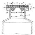
図14は、凍結乾燥工程を有効に行う先行技術の方法を図示している。容器600はリム614を含み、一定量の凍結乾燥されるべき薬剤616を有することを特徴としている。容器が凍結乾燥機に導入される前に、プラグ626を有する凍結乾燥用栓620が部分的に容器の首部618内に挿入される。プラグ626は、プラグが部分的に首部に挿入されたとき、容器の内部と凍結乾燥機とを連通し凍結乾燥工程中に発生する蒸気を容器外に逃がす溝622を含んでいる。凍結乾燥操作の後、凍結乾燥機内に設けられた棚が一般にフランジ624に対して下降され、その結果、プラグ626が完全に首部618内に挿入され容器内の薬剤を封止する。
【0004】
この封止操作の後、凍結乾燥用栓は容器に固定されねばならない。このようにするために、典型的には、容器が凍結乾燥機の滅菌環境から取り出され、凍結乾燥用封止体を容器に固定すべく、アルミニウム製締結キャップがフランジ624とリム614との周りに施される。締結キャップは、普通、凍結乾燥用封止体の中央部分の上に配置された取外し可能なパッドを組み込んでいる。取外し可能なパッドを取り除くことによって、ユーザーは凍結乾燥用封止体の中央部分にアクセスできる。このパッドは、ある程度、容器内容物取り出し証拠手段として機能する。取外し可能なパッドはまた、ある程度、凍結乾燥用封止体の頂部表面を清潔に保つための手段としても機能する。
【0005】
実際上、凍結乾燥薬剤は凍結乾燥用封止体にアクセスすべく締結キャップからパッドを取り除くことにより、使用する直前にアクセスされる。凍結乾燥用封止体に注射針を突き刺して薬剤を注射器に吸い出す。乾燥状態で保存された薬剤、例えば粉状または凍結乾燥状態の薬剤の場合、まず注射器で溶媒、例えば生理的食塩水を薬瓶に注入して粉状または凍結乾燥された薬剤を溶く。一旦溶けたなら、薬剤溶液は薬瓶から注射器に吸い込まれて使用される。
【0006】
【発明が解決しようとする課題】
一般的にこれらの封止組立体はうまく作用して使用前の薬剤を安全に保存するが、検討すべき欠点がある。アルミニウム製締結キャップの取外し可能パッドは鋭利な縁を有しているので、注意しないと医師の安全手袋を切ってしまうことがある。さらに先行技術の薬瓶で使われている締結キャップのほとんどは、封止体の頂部表面の滅菌状態を維持するようには構成されていないし、製薬メーカーでもそのようには処理していない。したがって、先行技術の凍結乾燥用封止体の中央部分は突き刺す前に、アルコール溶液などで滅菌しなければならない。
【0007】
製薬メーカー段階においてさらなる欠点が存在する。凍結乾燥は典型的には凍結乾燥機の滅菌環境内で行われる。凍結乾燥用封止体に設けられた溝は発生した蒸気に対し絞り通路となることがある。溝のせいで、成形型が標準のデザインに比べより複雑となる。また、凍結乾燥用封止体のプラグは、溝無しの場合よりも長くなり、より多くのゴム材料が必要とされることを意味する。
【0008】
既に説明したように、封止体を薬瓶に固定するためには、締結キャップを薬瓶のリムに施す装置等の他の装置が必要である。締結操作は、通常、凍結乾燥工程とは別で、凍結乾燥領域の滅菌環境の外で行われる。これは、製造工程にさらなる時間と費用とを要することになる。さらに、凍結乾燥用封止体の頂面は、締結操作の間、非滅菌環境下に曝されるので、エンド・ユーザーは、薬剤にアクセス可能となる前に、凍結乾燥用封止体の頂面をアルコール溶液等で消毒しなければならない。
【0009】
【課題を解決するための手段】
ボトルまたは薬瓶など薬剤容器用の凍結乾燥用封止組立体が開示される。凍結乾燥用封止組立体は、容器に自己支持され、薬剤が凍結乾燥工程下にある間、その工程中に発生する蒸気の自由な阻害されない通路をもたらす。凍結乾燥用封止組立体はその後、凍結乾燥室の滅菌環境内にある間に、容器を封止し、容器に固定され得る。凍結乾燥用封止組立体はこのように、凍結乾燥操作および引き続く完全な栓止め操作が一工程で起こるのを可能とし、凍結乾燥工程が行われる滅菌環境の外での付加的な手続の必要性を排除する。
【0010】
凍結乾燥用封止組立体は容器のリム周りに支持される本体を含んでいる。本体は容器の開かれた頂部に面している末端壁とリムの周りに位置されるスカートとを含んでいる。スカートはリムに係合可能な一つ以上の可撓性アームおよび凍結乾燥工程中に発生する蒸気が逃げ得る一つ以上の蒸気通路を含んでいる。本体は、容器内の薬剤が凍結乾燥工程下にある第1の位置と、凍結乾燥用封止組立体が容器を封止する第2位置との間で、リムの周りに位置付け可能である。
【0011】
容器の開かれた頂部を封止するエラストマー封止体が本体内に保持されている。エラストマー封止体は、容器の開かれた頂部を封止するプラグおよび容器の開かれた頂部から離れる方向に面する上面を有することを特徴とする。本体の末端壁はエラストマー封止体の上面の上に採取領域を限定する開口を画成している。膜がエラストマー封止体の上面の採取領域を覆って本体に取外し可能に固設されている。膜は、薬剤へのアクセスが所望されたとき医者が本体から膜を取り外すのを可能とする引張りつまみを含んでいる。
【0012】
使用の際には、エラストマー封止体が容器の開かれた頂部から離間されている第1の位置において、凍結乾燥用封止組立体が容器に固設される。凍結乾燥工程中に発生した蒸気は、本体に設けられた蒸気通路を経て容器から逃げることができる。凍結乾燥工程に引き続き、そして容器が凍結乾燥室内に残っている内に、凍結乾燥用封止組立体は、本体が容器のリムに係止されエラストマー封止体が容器の開かれた頂部を封止すべく位置された第2の位置に付勢され得る。したがって、凍結乾燥および完全な栓止め操作を凍結乾燥室の滅菌環境内の一工程で行うことができ、凍結乾燥工程が行われる滅菌環境の外での付加的な封止操作の必要性を排除する。
【0013】
エラストマー封止体は様々なゴム材から形成でき、本体は各種プラスチック材など各種の堅い材料から形成でき、膜は各種プラスチック材、複合材、紙材、金属箔材、TYVEK材等の材料から造ることができる。各コンポーネントは滅菌した状態で製薬メーカーに納入し、製薬メーカーは容器内の薬剤の処理中にこれらのコンポーネントを凍結乾燥用封止組立体に組み立てることができる。あるいは前もって組立て滅菌した凍結乾燥用封止組立体を製薬メーカーに納入し、製薬メーカーは組み立てられた滅菌済み凍結乾燥用封止組立体を薬剤の処理中に薬剤容器に取り付けることもできる。滅菌された膜は気密にエラストマー封止体の採取領域を覆うので、薬剤を使用する前にアルコール溶液などで上面を滅菌する必要がなくなる。また滅菌された膜は容器内の内容物の取り出し証拠手段としても機能する。
【0014】
もしも必要なら、ワッシャがエラストマー封止体の頂面に組み込まれてもよい。ワッシャは封止体の頂面上に配置され、エラストマー封止体の採取領域を画成する開口を含んでいる。膜はワッシャに取り外し可能に固定され、望むなら、本体の一部にまで延在される。
【0015】
【発明の実施の形態】
ここで述べる説明と図は薬瓶または瓶に関するものであるが、カプセル、広口びんあるいは類似の容器など、この分野で通常使用されているいかなるタイプの容器も容易にここで述べられている利点を享受するものであることは当業者であれば理解されるであろう。またここでは、外部から得た液体によって溶かすある量の乾燥された薬剤を収容した容器について述べているが、本発明はそれだけに制限されるものではないことは当業者に理解されるであろう。例えば、本発明は液状薬剤を収容する容器にも適用することができる。
【0016】
説明を単純にするために、本発明による滅菌封止組立体を最初に説明し、その後、本発明の滅菌封止組立体の特徴を凍結乾燥封止組立体において実現する方法を説明する。
【0017】
図1と図2において、本発明による滅菌封止組立体20は、末端部12と基端部14を有し一定量の薬剤16を収容した薬瓶またはびんなどの薬剤容器10に適用できる。後でさらに説明するが、一定量の薬剤16は例えば凍結乾燥工程を受けた薬剤であることもある。薬剤容器10は開いた頂部15で特徴付けられた首部18を含んでいる。開いた頂部15は、上面13と下面19を有するリム17で囲まれている。
【0018】
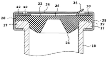
本発明による滅菌封止組立体20は薬剤容器の開いた頂部15を封止するためのエラストマー封止体22を含む。エラストマー封止体はゴム材から構成することができ、プラグ24を含む。プラグ24は、開いた頂部15をぴったりと閉じることができるように、首部18の直径“B”よりもわずかに大きいとまではいかなくても少なくともそれに等しい直径“A”を有することが好ましい。エラストマー封止体22はさらに、リム17の上面13に乗り、好ましくは、リムの上面13全体をほぼ覆うように構成されるフランジ28を有する。エラストマー封止体22は容器の開いた頂部から離れる方向に面する上面26を有する。上面26には採取領域26Aが設けられており、この領域にアクセスして医師は薬剤容器10内の薬剤16を取り出す。
【0019】
先に説明したように、従来の封止体においては、薬瓶を使用する前に医師は、普通、アルコール溶液などで上面26を滅菌しなければならなかった。この理由は、従来技術においては、封止体をびんに保持するために普通使われるアルミニウム製締結キャップは封止体の上面の滅菌状態を維持するようには構成されてもいないし処理もされていないからである。本発明による滅菌封止組立体20の利点は、滅菌封止組立体20がエンド・ ユーザーのレベルで直ちに使用できる滅菌された状態で提供されるように構成できることである。
【0020】
封止体20の滅菌状態を確保する一つの方法は、取外し可能パッドを組み込んだ従来のアルミニウム製締結キャップを排除して、ここで開示した構造に取り替えることである。ワッシャ30はエラストマー封止体22の上面26に配置されるべく形状付けられている。ワッシャ30の底面30Aは境界面37に沿ってエラストマー封止体の上面26と接触している。好ましくは、境界面37は底面30A全体を含む。ワッシャ30は上面26に配置された開口部32を区画し、これが上面26の採取領域26Aの範囲を定める。
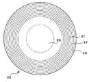
【0021】
図2は、ワッシャの上面35に沿ってワッシャ30に対して取り外し可能に取り付けてある膜34を示す。膜34は上面26の採取領域26Aを覆って無菌状態に保護し、好ましくはエラストマー封止体の採取領域26Aを気密に封止するようにワッシャに取り付けられている。膜34は好ましくは引張りつまみ36を有し、それによってエラストマー封止体へアクセスしたい場合、ユーザーはワッシャから膜34を取外すことができるようになっている。
【0022】
薬瓶封止体20全体は、例えば、締結キャップ38によって薬瓶のリム17に固定できる。締結キャップ38はプラスチックや金属等適当な堅い材料で形成できる。ここに示したように、締結キャップ38はワッシャの上面35とリム17の下面19に係合してワッシャ30をエラストマー封止体のフランジ28にしっかりと押し付け、両者を薬瓶のリム17に固定している。滅菌状態の維持ができるだけでなく、膜34に選ばれる材料は鋭利な縁を避けることにより、前に述べた従来のアルミニウム製締結キャップの問題を避けることが好ましい。また採取領域26Aの滅菌状態を確保できるだけでなく、膜34が薬剤容器10の内容物に対する取り出し証拠手段となることは当業者であれば理解されるであろう。
【0023】
エラストマー封止体22、ワッシャ30および膜34を滅菌状態で別々に製薬メーカーに納め、製薬メーカーが薬剤容器の処理中にそれらを滅菌封止組立体20に組み立てることができることはこの分野に精通した者には理解されるであろう。あるいは、滅菌封止組立体20を前もって組み立て滅菌状態で製薬メーカーに納入し、製薬メーカーが薬瓶封止組立体20を単一ユニットとして処理できるようにすることも可能である。
【0024】
エラストマー封止体22は様々なゴム材から形成でき、ワッシャ30は各種プラスチック材を含む適当な堅い材料から形成できる。膜34はエラストマー封止体の滅菌状態を維持するプラスチック材、複合材、紙材、金属箔材、TYVEK材等の適当な材料から造ることができる。膜34は接着剤、熱シール、接合、その他膜とワッシャの材料に合った方法でワッシャ30に固定できる。エラストマー封止体22とワッシャ30は同時射出成形法等で一体に形成することができることは当業者には理解されるであろう。同様に、ワッシャ30と膜34も必要に応じて同時射出成形法等で一体に形成できる。あるいは3つのすべてのコンポーネント、すなわちエラストマー封止体、ワッシャおよび膜を必要に応じて適当な同時射出成形法で一体に形成することもできる。
【0025】
ワッシャ30とエラストマー封止体22は全面に亘って接触させて、両者の間で高いシール性能を与えるようにすることが望ましい。特に、ワッシャ30とエラストマー封止体22を別々に納入する場合、成形異常や寸法異常などに対してワッシャ30と上面26との間のシール接触を高めるために、境界面37にある構造を組み込んでもよい。図5に示すように、1つ以上の封止リブ42をワッシャ30に形成することができる。締結キャップ38の力によって封止リブ42はエラストマー封止体の上面26に食い込んで両者間のシール接触を高める。あるいは、図6と図7に示すように、エラストマー封止体の上面26に封止リブ27を形成してもよい。これによってワッシャとエラストマー封止体間のシール接触が高められる。
【0026】
また、エラストマー封止体22のフランジ28と容器のリム17との間の境界面39に封止リブ(図示せず)を設けることができることが理解されるであろう。フランジ28またはリム17上のいずれかに設けたこれらの封止リブは両者のシール接触を高める。
【0027】
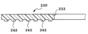
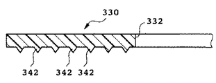
図5から図7において、封止リブ27と42は断面が丸く示されている。図8は四角い断面の封止リブ242を有するワッシャの実施例230である。あるいは、図9に示すように、ワッシャ330は尖った断面の封止リブ342で特徴づけることもできる。これらの断面形状のいずれもエラストマー封止体の上面26に形成した封止リブに適用できることは当業者には明らかであろう。
【0028】
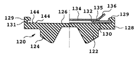
図3は、本発明による滅菌封止組立体の変形120を示す。エラストマー封止体122は、プラグ124とフランジ128を有する。ワッシャ130をしっかりと収容保持するポケット131を形成するブレース(brace) 129によって、ワッシャ130はエラストマー封止体122に保持されている。先に述べたように、1つ以上の封止リブ144をエラストマー封止体122の上面126に設けることができ、これによってワッシャ130と上面126との間のシール接触を高めることができる。膜134は先に述べたような方法でワッシャ130に固定される。ここで、締結キャップ(図示せず)をブレース129と容器のリムの周りに固定することによって、薬瓶封止体120が薬剤容器(図示せず)の首部18に保持される。
【0029】
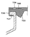
前記の滅菌封止組立体20,120は、その構造の一部としてワッシャ30,130を使用したが、ワッシャに先立って、膜734を前もって締結キャップ738の上に直接取り付けることも当業者の力量範囲内である。図4を参照。その後、滅菌された環境において、エラストマー封止体722とリム717を覆うように締結キャップ738と膜734を取付けることができる。滅菌領域と締結領域との間での取扱操作中に、膜734と締結キャップ738がバラバラになったり容器の頂部から外れることがないように、必要に応じて、膜734とエラストマー封止体722との間にリブ780などの構造を設けることができる。これで膜734が付着できる第二の領域ができるので、取扱中に膜と締結キャップが乱れたり容器から外れることはない。
【0030】
先に説明したように、従来の薬瓶封止体の問題点の一つは、凍結乾燥工程と栓をする工程を一つの工程で行なえるように封止体が設計されていないので、凍結乾燥室の滅菌環境の外部で行なわれる締結操作などの栓をする別の工程を必要とすることである。凍結乾燥室の構成および凍結乾燥室が提供する構造によっては、本発明の滅菌封止組立体20は凍結乾燥室の滅菌環境内において容器10に取り付けることができる。例えば、容器内で薬剤が凍結乾燥されているときに滅菌封止組立体を保持し、凍結乾燥後に封止組立体を容器に取り付けて封止するための構造を凍結乾燥室内に設けてもよい。
【0031】
凍結乾燥室の外部での締結操作を行なった場合でも、滅菌封止組立体に膜が設けられているので薬剤を取り出す前にアルコール溶液などで封止体の採取領域を滅菌する必要性がなくなる。
【0032】
しかし本発明の滅菌封止体の特徴を、容器に自己保持される凍結乾燥封止組立体に組み込むと便利であろう。そのような凍結乾燥封止組立体は、凍結乾燥装置に高価な変更を行なう必要もなく、凍結乾燥室の滅菌環境内で凍結乾燥工程が終わった後に最終的に容器に封止されるのが理想的である。凍結乾燥封止組立体は、凍結乾燥と完全な栓封止操作を同時に容易にする。このため処理コストが低減し、特に凍結乾燥を行なう滅菌環境の外で締結操作等の追加処理操作が不要となる。
【0033】
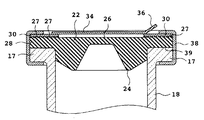
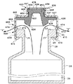
さらに、本発明による凍結乾燥封止組立体の実施例400が示してある図10から図13を参照する。凍結乾燥封止組立体400は、先に説明した滅菌封止組立体20の特徴を有する滅菌された薬瓶封止体420を組み込んでいる。滅菌された薬瓶封止体420は、封止体が容器に保持されている間、容器10内の薬剤16の凍結乾燥が行なえるように構成した本体460内に組み込まれている。凍結乾燥の後に、容器10が凍結乾燥機の滅菌環境内に配置されている間、本体460は容器10に対して自己封止し、それによって滅菌された薬瓶封止体420が容器の開いた頂部をシールする。これにより締結操作等の追加処理工程の必要がなくなる。
【0034】
本体460は容器の開いた頂部15の上に配置した末端壁462を有する。末端壁462は容器のリム17を囲むスカート464と接続している。スカート464はスカートの基部端に、L字型の把持部471を有する1つ以上の可撓性側壁470を含む。L字型把持部471と末端壁462との中間に1つ以上の可撓性ラッチ472が形成されている。図10から分かるように、可撓性ラッチ472はスカート464の内部に向かって内側に傾いている。可撓性側壁470をリム17の周りに付勢することによって、本体460を最初にリム17の周囲に取り付け得る。コンポーネントの各寸法は、第一位置においてリム17が1つ以上の可撓性側壁のL字型把持部471と1つ以上の可撓性ラッチ472との間に保持されるように選定する。1つ以上の蒸気通路474がスカート464に形成されている。本体460がその第一位置に配置されたとき、蒸気通路474はびんの開いた頂部15に連通し凍結乾燥工程において発生した蒸気“V”を容器10の内部から逃がす。
【0035】
先の場合と同様に、滅菌された薬瓶封止体420は、本体460内に保持されているエラストマー封止体422を含む。先の場合と同様に、エラストマー封止体422は、凍結乾燥封止組立体400がリム17に関して第二位置(図12)に配置されているとき、首部18を完全に閉じて容器の開いた頂部15をシールするように構成されたプラグ424を含む。前記と同様に、エラストマー封止体422は上面426を含み、エンド・ユーザーはそこにアクセスして容器10内の薬剤16を取り出す。上面426には本体400を通って末端壁462に定めた中央通路を介してアクセスできる。必要に応じて、エラストマー封止体は本体の末端壁462の内側部分と面接触するように配置されたフランジ428も含んでもよい。フランジ428は本体460が第二位置(図12)あるときリム17の上面を覆うように構成されている。フランジ428に1つ以上の封止リブ427を設けてフランジと末端壁462との間のシール接触を高めることができる。あるいは、封止リブを末端壁462の内側部分に設けることもできる。封止リブ427は図5から図9に示したような適当な形状を採ることができる。
【0036】
図10に示すように、エラストマー封止体422は直立突出部450を含むことができる。したがってエラストマー封止体の上面426は直立突出部450上に設けられる。本体460は末端壁462から延びる管状延出部468を含むことができる。管状延出部468は中央通路466を定めるフランジ467で終わっている。エラストマー封止体422の直立突出部450は、管状延出部468内に形成されたノッチ部469内に嵌合するリップ456を設けることにより管状延出部468内に保持することができる。リップ456はノッチ部469に捕捉されブラケット467の内側部分に対して気密に保持される。1つ以上の封止リブ452をエラストマー封止体の直立突出部450に設けて管状延出部468の内側部分とシール接触させることができる。あるいはこれらの封止リブを管状延出部468の内側部分に設けることもできる。いずれの場合も、封止リブ452は図5から図9に示したような適当な形状を採ることができる。
【0037】
凍結乾燥封止組立体400上に膜434を取り付けてエラストマー封止体422の上面426を保護し無菌状態で覆うことができる。膜434は引張りつまみ436を有する。図10に示すように、膜434は本体のフランジ467に取り付けられ、上面426を保護するように覆っている。
【0038】
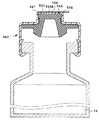
あるいは、必要に応じて、図13に示すように、エラストマー封止体522の上面526にワッシャ530を配置することもできる。ワッシャ530は上面の採取領域526Aを定める開口532を含む。ワッシャ530はエラストマー封止体の上面に保持され、その外縁が本体560のフランジ567によって定められる中央通路566に隣接するように寸法を定めることができる。あるいは、例えば、図2、図5および図6に示す構成のように、必要に応じてエラストマー封止体の上面とフランジ567の間に保持されるようにワッシャの寸法を定めることもできる。膜534をワッシャ530と面接触させてエラストマー封止体522の採取領域526Aを保護するように覆うことができる。必要に応じて、膜534は延長させ本体560のフランジ567と面接触させて固定することができる。
【0039】
先の場合と同様に、エラストマー封止体422は適当なゴム材で形成でき、本体460はプラスチック材など適当な堅い材料から形成できる。膜434は各種プラスチック材、複合材、紙材、金属箔材、TYVEK材などから造ることができる。各コンポーネントは滅菌した状態で製薬メーカーに納入し、製薬メーカーは処理工程の一部としてそれらコンポーネントを組み立てることができる。あるいはコンポーネントを部品メーカーが前もって組立て滅菌し、組み立てられた滅菌済み凍結乾燥封止組立体400を製薬メーカーに納入することもできる。
【0040】
必要に応じて、本体460とエラストマー封止体422を同時射出成形により一体に形成したり、膜434と本体460を同時射出成形により一体に形成したり、本体460、エラストマー封止体422および膜434のすべてを一体射出成形により一体に形成することができる。ワッシャ530を採用する場合(図13参照)、これは前記コンポーネントのいずれとでも、個々にあるいはまとめて、同時射出成形により一体に形成することができる。本発明の凍結乾燥封止組立体400によれば、凍結乾燥機の滅菌環境内において薬剤の凍結乾燥操作と完全な栓止め操作をおこなうことができ、凍結乾燥機の滅菌環境外での締結操作など追加の栓止め操作の必要がない。
【0041】
図10は凍結乾燥封止組立体400がその第一の位置にある状態を示しており、この位置において容器内の薬剤16は凍結乾燥される。薬剤16が容器10に入れられた後に凍結乾燥封止組立体をリム17に嵌合させて図10に示す位置に取り付けることができる。図から分かるように、この位置においてプラグ424は容器の首部には挿入されておらず、容器の開いた頂部15から離れた位置にある。薬剤の充填された容器は凍結乾燥機などの適当な凍結乾燥室に入れられて、薬剤16の凍結乾燥をおこなうことができる。凍結乾燥封止組立体400は容器に対して自己支持しているので、凍結乾燥工程において凍結乾燥封止組立体を支持するための構造を凍結乾燥室内に追加する必要はない。容器の開いた頂部に対してプラグ424が離れているため、凍結乾燥工程において発生した蒸気“V”は本体460の蒸気通路474を通って自由に容器10から出て行くことができる。
【0042】
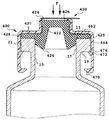
薬剤16の凍結乾燥に続いて、薬剤を封止するために薬剤容器10に栓をしなければならない。図12は凍結乾燥封止組立体400が第二の位置に付勢された状態を示す。この位置において、凍結乾燥工程の後に容器10が凍結乾燥機の滅菌環境内に保たれている間に、エラストマー封止体422が付勢されてびんの開いた頂部15にシール接触されている。凍結乾燥機に従来から設けられている棚などによって与えられる力“F”が本体460に加えられる。本体460はリム17の基部の方へ付勢され、可撓性ラッチ472は最初の内側に傾いた姿勢から外方に向けて押しのけられてリム17の側面21を通過する。可撓性ラッチ472は側面21を通過した後に、自由となって最初の内側に傾いた姿勢を取り戻し、その結果可撓性ラッチはリムの下面に係止する。したがって本体460は容器に対して第二の位置に係止され、凍結乾燥封止組立体が容器にしっかりと固定される。エラストマー封止体422は容器の開いた頂部15を封止するので、蒸気通路474は開いた頂部15から遮断される。したがって薬剤は容器10内に無菌状態で安全に封止される。
【0043】
凍結乾燥封止組立体400が第二の位置に付勢されたとき、プラグ424が首部18の中に押し込まれてびんの開いた頂部15を封止するように各コンポーネントの寸法を定めあるいは構成することができることが分かる。フランジの下面429はリムの上面13に面接触し、これらコンポーネントの間がシールされる。必要に応じて、封止リブ(図示せず)をフランジの下面429とリムの上面13との間に設けることによってこれらの間のシール接触を高めることができることが理解できるであろう。さらに、蒸気通路474が薬剤容器の開いた頂部15から遮断されるので、凍結乾燥を行なった滅菌環境内で薬剤容器は凍結乾燥封止組立体によって完全に封止される。膜434はエラストマー封止体の上面426を気密に保護する。薬剤を使用したいとき、エンド・ユーザーは膜434を取り除くだけでアルコール溶液などで採取領域を滅菌する必要はない。
【0044】
本発明の更なる態様は添付クレームの主旨および範囲から逸脱することなく実施することができ、本発明が上記の特定の実施例に制約されるものではないことがこの分野に精通した者には理解されるであろう。
【図面の簡単な説明】
【図1】本発明による容器または薬瓶用滅菌封止体の斜視図である。
【図2】本発明による滅菌封止体の一実施例の断面図である。
【図3】本発明による滅菌封止体を構成する別の方法を示す断面図である。
【図4】本発明による滅菌封止体を構成する別の方法を示す断面図である。
【図5】滅菌効果を高めるリブを組み込んだ、本発明による滅菌封止体の一実施例の断面図である。
【図6】図5に示した滅菌封止体の別の実施例を示す断面図である。
【図7】本発明による滅菌封止体に利用できるエラストマー封止体の平面図である。
【図8】本発明による滅菌封止体用ワッシャの断面図である。
【図9】本発明による滅菌封止体用ワッシャの別の例の断面図である。
【図10】本発明による薬剤容器用凍結乾燥封止組立体の断面図である。
【図11】図10の凍結乾燥封止組立体に利用可能な本体を示す斜視図である。
【図12】凍結乾燥工程に続く図10の凍結乾燥封止組立体を示す断面図である。
【図13】本発明による凍結乾燥封止組立体の別の実施例を示す断面図である。
【図14】凍結乾燥工程を有効とする先行技術の方法を示す断面図である。
【符号の説明】
10 (薬剤)容器
15 開いた頂部
16 薬剤
17,717 リム
18 首部
20,120 滅菌封止組立体
22,122,422,522,722 エラストマー封止体
24,124,424 プラグ
26,426,526 上面
26A,526A 採取領域
28,128 フランジ
30,130,230,330,530 ワッシャ
34,134,434,534,734 膜
38,738 締結キャップ
42,242,342 封止リブ
400 凍結乾燥封止組立体
420 薬瓶封止体
424 プラグ
450 直立突出部
460,560 本体
464 スカート
467,567 フランジ
470 可撓性側壁
472 可撓性ラッチ
474 蒸気通路[0001]
BACKGROUND OF THE INVENTION
The present invention relates to a freeze-drying sealing assembly for a drug container, and more particularly to a freeze-drying sealing assembly for a drug container that is self-supported by the container and can be easily sealed to the container in a sterile environment of the freeze-drying chamber. .
[0002]
[Prior art]
In order to extend the shelf life of a drug, pharmaceutical manufacturers place the drug under a lyophilization process. In the freeze-drying process, the liquid drug placed in a container or a medicine bottle is placed under the freeze-drying process in order to extract moisture from the drug while leaving the active ingredient of the drug in a crystalline state.
[0003]
FIG. 14 illustrates a prior art method for effectively performing a freeze-drying process.
[0004]
After this sealing operation, the freeze-drying stopper must be fixed to the container. To do this, the container is typically removed from the sterilization environment of the lyophilizer and an aluminum fastening cap is placed around the
[0005]
In practice, the lyophilized drug is accessed just prior to use by removing the pad from the fastening cap to access the lyophilization seal. The needle is inserted into the freeze-drying sealing body, and the drug is sucked into the syringe. In the case of a drug stored in a dry state, for example, a powdered or lyophilized drug, first, a solvent, for example, physiological saline is injected into a medicine bottle with a syringe to dissolve the powdered or lyophilized drug. Once dissolved, the drug solution is drawn from the vial into a syringe for use.
[0006]
[Problems to be solved by the invention]
In general, these sealing assemblies work well to safely store the drug before use, but have drawbacks to consider. The removable pad of the aluminum fastening cap has sharp edges that can cut off the doctor's safety gloves if care is not taken. Furthermore, most of the fastening caps used in prior art vials are not configured to maintain the sterilization of the top surface of the seal and are not treated as such by pharmaceutical manufacturers. Therefore, the central portion of the prior art lyophilization seal must be sterilized with an alcohol solution or the like before being pierced.
[0007]
There are further drawbacks at the pharmaceutical manufacturer stage. Freeze drying is typically performed within the sterile environment of the freeze dryer. The groove provided in the freeze-drying sealing body may become a throttle passage for the generated vapor. Grooves make the mold more complex than standard designs. Moreover, the plug of the freeze-drying sealing body is longer than that without the groove, which means that more rubber material is required.
[0008]
As already described, in order to fix the sealing body to the medicine bottle, another device such as a device for applying a fastening cap to the rim of the medicine bottle is required. The fastening operation is usually performed outside the sterilization environment in the freeze-drying area, separately from the freeze-drying process. This requires additional time and expense for the manufacturing process. In addition, the top surface of the freeze-drying seal is exposed to a non-sterile environment during the fastening operation, so that the end user can access the top of the freeze-drying seal before the drug is accessible. The surface must be disinfected with an alcohol solution.
[0009]
[Means for Solving the Problems]
A freeze-drying sealing assembly for a drug container, such as a bottle or drug bottle, is disclosed. The freeze-drying seal assembly is self-supported in the container and provides a free, unobstructed passage for vapors generated during the process while the drug is under the freeze-drying process. The lyophilization seal assembly can then seal and secure the container while in the sterile environment of the lyophilization chamber. The freeze-drying seal assembly thus allows the freeze-drying operation and subsequent complete plugging operation to occur in one step, requiring additional procedures outside the sterile environment where the freeze-drying step takes place. Eliminate sex.
[0010]
The freeze-drying sealing assembly includes a body that is supported around the rim of the container. The body includes a distal wall facing the open top of the container and a skirt positioned around the rim. The skirt includes one or more flexible arms engageable with the rim and one or more steam passages through which steam generated during the lyophilization process can escape. The body can be positioned around the rim between a first position where the drug in the container is under a lyophilization process and a second position where the lyophilization sealing assembly seals the container.
[0011]
An elastomer seal that seals the open top of the container is held in the body. The elastomeric seal is characterized by having a plug that seals the open top of the container and an upper surface that faces away from the open top of the container. The end wall of the body defines an opening defining a collection area on the upper surface of the elastomeric seal. A membrane covers the sampling region on the upper surface of the elastomer sealing body and is fixed to the main body so as to be removable. The membrane includes a pull tab that allows the physician to remove the membrane from the body when access to the medication is desired.
[0012]
In use, the freeze-drying seal assembly is secured to the container at a first position where the elastomer seal is spaced from the open top of the container. Steam generated during the freeze-drying process can escape from the container through a steam passage provided in the main body. Following the lyophilization process and while the container remains in the lyophilization chamber, the lyophilization seal assembly seals the open top of the container with the body locked to the rim of the container. It can be biased to a second position positioned to stop. Thus, lyophilization and complete stoppering can be performed in one step within the sterilization environment of the lyophilization chamber, eliminating the need for additional sealing operations outside the sterilization environment where the lyophilization process is performed. To do.
[0013]
The elastomer sealing body can be formed from various rubber materials, the main body can be formed from various hard materials such as various plastic materials, and the film is made from various plastic materials, composite materials, paper materials, metal foil materials, TYVEK materials, etc. be able to. Each component is delivered to the pharmaceutical manufacturer in a sterilized state, and the pharmaceutical manufacturer can assemble these components into a freeze-drying sealing assembly during processing of the drug in the container. Alternatively, the pre-assembled and sterilized freeze-drying seal assembly can be delivered to a pharmaceutical manufacturer, and the pharmaceutical manufacturer can attach the assembled sterile freeze-drying seal assembly to the drug container during drug processing. Since the sterilized membrane covers the collection area of the elastomer sealing body in an airtight manner, it is not necessary to sterilize the upper surface with an alcohol solution or the like before using the drug. The sterilized membrane also functions as a proof means for removing the contents in the container.
[0014]
If necessary, a washer may be incorporated into the top surface of the elastomeric seal. A washer is disposed on the top surface of the seal and includes an opening that defines a collection area for the elastomer seal. The membrane is removably secured to the washer and extends to a portion of the body if desired.
[0015]
DETAILED DESCRIPTION OF THE INVENTION
Although the description and figures described here relate to vials or bottles, any type of container commonly used in the field, such as capsules, jars, or similar containers, can easily benefit from the advantages described herein. Those skilled in the art will appreciate that they enjoy it. It will also be appreciated by those skilled in the art that although a container is described herein that contains a quantity of dried drug that is dissolved by an externally obtained liquid, the present invention is not so limited. For example, the present invention can be applied to a container for storing a liquid medicine.
[0016]
For simplicity of explanation, a sterile seal assembly according to the present invention will first be described, followed by a description of how the features of the sterile seal assembly of the present invention are implemented in a lyophilized seal assembly.
[0017]
1 and 2, the
[0018]
The
[0019]
As described above, in the conventional sealing body, before using the medicine bottle, a doctor usually has to sterilize the
[0020]
One way to ensure the sterilization of the
[0021]
FIG. 2 shows the
[0022]
The entire medicine
[0023]
It is well known in the art that the
[0024]
The
[0025]
It is desirable that the
[0026]
It will also be appreciated that sealing ribs (not shown) can be provided at the
[0027]
5 to 7, the sealing
[0028]
FIG. 3 shows a
[0029]
Although the
[0030]
As explained above, one of the problems with the conventional vial sealer is that the sealer is not designed so that the freeze-drying step and the capping step can be performed in one step. It requires another process of plugging such as a fastening operation performed outside the sterilization environment of the drying room. Depending on the configuration of the lyophilization chamber and the structure provided by the lyophilization chamber, the
[0031]
Even when the fastening operation is performed outside the freeze-drying chamber, since the sterilization sealing assembly is provided with a film, it is not necessary to sterilize the collection region of the sealing body with an alcohol solution before taking out the medicine. .
[0032]
However, it may be convenient to incorporate the features of the sterile seal of the present invention into a lyophilized seal assembly that is self-retaining in a container. Such a lyophilization seal assembly does not require expensive modifications to the lyophilization apparatus and is ultimately sealed to the container after the lyophilization process is completed within the sterilization environment of the lyophilization chamber. Ideal. The lyophilization seal assembly facilitates lyophilization and a complete plug sealing operation simultaneously. This reduces processing costs and eliminates the need for additional processing operations such as fastening operations outside a sterilizing environment where lyophilization is performed.
[0033]
Reference is further made to FIGS. 10-13, in which an
[0034]
The
[0035]
As before, the sterilized
[0036]
As shown in FIG. 10, the
[0037]
A
[0038]
Alternatively, as shown in FIG. 13, a
[0039]
As in the previous case, the
[0040]
If necessary, the
[0041]
FIG. 10 shows the
[0042]
Following lyophilization of
[0043]
Each component is dimensioned or configured so that when the
[0044]
It will be apparent to those skilled in the art that further aspects of the present invention may be practiced without departing from the spirit and scope of the appended claims, and that the invention is not limited to the specific embodiments described above. Will be understood.
[Brief description of the drawings]
FIG. 1 is a perspective view of a sterilization seal for a container or medicine bottle according to the present invention.
FIG. 2 is a cross-sectional view of one embodiment of a sterilized sealed body according to the present invention.
FIG. 3 is a cross-sectional view showing another method of constructing a sterilized sealed body according to the present invention.
FIG. 4 is a cross-sectional view showing another method of constructing a sterilized sealed body according to the present invention.
FIG. 5 is a cross-sectional view of one embodiment of a sterile seal according to the present invention incorporating ribs that enhance the sterilization effect.
6 is a cross-sectional view showing another embodiment of the sterile sealing body shown in FIG.
FIG. 7 is a plan view of an elastomer sealing body that can be used in a sterilization sealing body according to the present invention.
FIG. 8 is a cross-sectional view of a washer for a sterilized sealed body according to the present invention.
FIG. 9 is a cross-sectional view of another example of a washer for a sterilized sealed body according to the present invention.
FIG. 10 is a cross-sectional view of a freeze-drying sealing assembly for a drug container according to the present invention.
11 is a perspective view showing a main body that can be used in the freeze-drying sealing assembly of FIG. 10;
12 is a cross-sectional view of the lyophilization seal assembly of FIG. 10 following a lyophilization process.
FIG. 13 is a cross-sectional view illustrating another embodiment of a freeze-drying sealing assembly according to the present invention.
FIG. 14 is a cross-sectional view showing a prior art method for enabling a freeze-drying process.
[Explanation of symbols]
10 (drug) container
15 Open top
16 drugs
17,717 rim
18 Neck
20,120 Sterilization sealing assembly
22,122,422,522,722 elastomer sealing body
24, 124, 424 plug
26,426,526 top surface
26A, 526A Collection area
28, 128 flange
30, 130, 230, 330, 530 washers
34,134,434,534,734 membrane
38,738 Fastening cap
42,242,342 Sealing rib
400 Freeze-drying sealing assembly
420 Medicine Bottle Sealing Body
424 plug
450 Upright protrusion
460, 560 body
464 Skirt
467,567 flange
470 Flexible Side Wall
472 Flexible Latch
474 Steam passage
Claims (10)
容器の開いた頂部の周りに固設され、容器の開いた頂部の上に配置される末端壁および容器のリムを取り囲むスカートを有する本体であって、末端壁には中央通路が設けられ、スカートは末端部と基端部と該両者間に形成された一つ以上の蒸気通路を有し、さらに本体は、容器のリムと協働しスカートの末端部と基端部との中間に設けられた一つ以上の可撓性ラッチを含み、蒸気通路が開いた頂部に連通するよう開いた頂部から上昇された第1の位置、および、可撓性ラッチが本体をリムに係止し蒸気通路が容器の開いた頂部に連通しない第2の位置を有する本体と、
本体が第2の位置にあるとき容器の開いた頂部を封止するよう前記本体に固設されたエラストマー封止体であって、容器の開いた頂部を封止するプラグと末端壁の中央通路に面する頂面とを有し、プラグは、開いた頂部がスカートの蒸気通路に連通するよう本体が第1の位置にあるとき容器の開いた頂部から離間するよう寸法付けられているエラストマー封止体と、
末端壁の中央通路を横断して取外し可能に固設され、エラストマー封止体の頂面を気密に覆う膜と、を備え、
前記本体はさらに、末端壁の中央通路を取り囲む管状延出部を含み、前記エラストマー封止体はさらに、前記管状延出部内に固定的に保持された直立突出部を含み、エラストマー封止体の頂面が前記直立突出部に設けられ、
エラストマー封止体は、本体の末端壁に当接して保持されるフランジ部を有し、
エラストマー封止体はさらに、エラストマー封止体の直立突出部と本体の管状延出部との間に配置された複数のシールリブと、エラストマー封止体のフランジ部と本体の末端壁との間に配置された複数のシールリブと、を備え、
前記エラストマー封止体の直立突出部にはリップが設けられ、管状延出部内には前記リップを捕捉するノッチが形成されていることを特徴とする凍結乾燥封止組立体。A lyophilized seal assembly for a drug container having an open top and a rim surrounding the open top,
A body fixed around the open top of the container and having a skirt surrounding the rim of the container and an end wall disposed on the open top of the container, the end wall having a central passage, Has a distal end, a proximal end, and one or more steam passages formed therebetween, and the body cooperates with the rim of the container and is provided between the distal end and the proximal end of the skirt. A first position that includes one or more flexible latches, wherein the steam passage is raised from the open top to communicate with the open top, and the flexible latch locks the body to the rim and the steam passage A body having a second position that does not communicate with the open top of the container;
An elastomeric seal fixed to the body to seal the open top of the container when the body is in the second position, the plug and the central passage in the end wall sealing the open top of the container And an elastomeric seal dimensioned to be spaced from the open top of the container when the body is in the first position such that the open top communicates with the steam passage of the skirt. A stationary body,
A membrane fixed removably across the central passage of the end wall and hermetically covering the top surface of the elastomeric seal ,
The body further includes a tubular extension surrounding a central passage in the end wall, and the elastomeric seal further includes an upstanding projection fixedly retained within the tubular extension, A top surface is provided on the upright projection,
The elastomer sealing body has a flange portion that is held in contact with the end wall of the main body,
The elastomer sealing body further includes a plurality of seal ribs disposed between the upright protruding portion of the elastomer sealing body and the tubular extension of the main body, and between the flange portion of the elastomer sealing body and the end wall of the main body. A plurality of seal ribs arranged,
Said upright projection of the elastomeric closure lip is provided, lyophilization closure assembly to the tubular extension portion, characterized that you have formed a notch for capturing the lip.
容器の開いた頂部の周りに固設され、容器の開いた頂部の上に配置される末端壁および容器のリムを取り囲むスカートを有する本体であって、末端壁には中央通路が設けられ、スカートは末端部と基端部と該両者間に形成された一つ以上の蒸気通路を有し、さらに本体は、容器のリムと協働しスカートの末端部と基端部との中間に設けられた一つ以上の可撓性ラッチを含み、蒸気通路が開いた頂部に連通するよう開いた頂部から上昇された第1の位置、および、可撓性ラッチが本体をリムに係止し蒸気通路が容器の開いた頂部に連通しない第2の位置を有する本体と、
本体が第2の位置にあるとき容器の開いた頂部を封止するよう前記本体に固設されたエラストマー封止体であって、容器の開いた頂部を封止するプラグと本体の末端壁に当接して保持されるフランジ部と末端壁の中央通路に面する頂面とを有し、プラグは、開いた頂部がスカートの蒸気通路に連通するよう本体が第1の位置にあるとき容器の開いた頂部から離間するよう寸法付けられているエラストマー封止体と、
エラストマー封止体の頂面に面接触して固設され、末端壁の中央通路に面する開口を画成するワッシャと、
ワッシャの開口を横断して取外し可能に固設され、エラストマー封止体の頂面を気密に覆う膜と、を備え、
前記本体は末端壁の中央通路を取り囲む管状延出部を含み、前記エラストマー封止体は前記管状延出部内に固定的に保持された直立突出部を含み、エラストマー封止体の頂面が直立突出部に設けられ、
エラストマー封止体は、エラストマー封止体の直立突出部と本体の管状延出部との間に配置された複数のシールリブと、前記エラストマー封止体のフランジ部と本体の末端壁との間に配置された複数のシールリブとを備え、
前記エラストマー封止体の直立突出部にはリップが設けられ、管状延出部内には前記リップを捕捉するノッチが形成されていることを特徴とする凍結乾燥封止組立体。A lyophilized seal assembly for a drug container having an open top and a rim surrounding the open top,
A body fixed around the open top of the container and having a skirt surrounding the rim of the container and an end wall disposed on the open top of the container, the end wall having a central passage, Has a distal end, a proximal end, and one or more steam passages formed therebetween, and the body cooperates with the rim of the container and is provided between the distal end and the proximal end of the skirt. A first position that includes one or more flexible latches, wherein the steam passage is raised from the open top to communicate with the open top, and the flexible latch locks the body to the rim and the steam passage A body having a second position that does not communicate with the open top of the container;
An elastomer sealing body fixed to the main body so as to seal the open top of the container when the main body is in the second position, the plug sealing the open top of the container and the end wall of the main body A flange portion that is held against and a top surface facing the central passage of the end wall, the plug being in the container when the body is in the first position so that the open top portion communicates with the steam passage of the skirt. An elastomeric seal dimensioned to be spaced from the open top;
A washer fixed in surface contact with the top surface of the elastomer encapsulant and defining an opening facing the central passage of the end wall;
A film that is removably fixed across the opening of the washer and hermetically covers the top surface of the elastomer sealing body ,
The body includes a tubular extension surrounding a central passage in the end wall, the elastomeric seal includes an upstanding protrusion fixedly held within the tubular extension, and the top surface of the elastomer seal is upright Provided in the protrusion,
The elastomer sealing body includes a plurality of seal ribs disposed between the upright protruding portion of the elastomer sealing body and the tubular extension portion of the main body, and between the flange portion of the elastomer sealing body and the end wall of the main body. A plurality of arranged seal ribs,
Said upright projection of the elastomeric closure lip is provided, lyophilization closure assembly to the tubular extension portion, characterized that you have formed a notch for capturing the lip.
容器の開いた頂部の周りに固設され、容器の開いた頂部の上に配置される末端壁および容器のリムを取り囲むスカートを有する本体であって、末端壁には中央通路が設けられ、スカートは末端部と基端部と該両者間に形成された一つ以上の蒸気通路を有し、さらに本体は、容器のリムと協働しスカートの末端部と基端部との中間に設けられた一つ以上の可撓性ラッチを有し、蒸気通路が開いた頂部に連通するよう開いた頂部から上昇された第1の位置、および、可撓性ラッチが本体をリムに係止し蒸気通路が容器の開いた頂部に連通しない第2の位置を有する本体と、
本体が第2の位置にあるとき容器の開いた頂部を封止するよう前記本体に固設されたゴム製の封止体であって、容器の開いた頂部を封止するプラグと本体の末端壁に当接して保持されるフランジ部と末端壁の中央通路に面する頂面とを有し、プラグは、開いた頂部がスカートの蒸気通路に連通するよう本体が第1の位置にあるとき容器の開いた頂部から離間するよう寸法付けられているゴム製の封止体と、
ゴム製の封止体の頂面に面接触して固設され、末端壁の中央通路に面する開口を画成するプラスチック製のワッシャと、
ワッシャの開口を横断して取外し可能に固設され、ゴム製の封止体の頂面を気密に覆う箔の膜と、を備え、
前記本体は末端壁の中央通路を取り囲む管状延出部を含み、前記ゴム製の封止体は前記管状延出部内に固定的に保持された直立突出部を含み、ゴム製の封止体の頂面が直立突出部に設けられ、
ゴム製の封止体は、ゴム製の封止体の直立突出部と本体の管状延出部との間に配置された複数のシールリブと、前記ゴム製の封止体のフランジ部と本体の末端壁との間に配置された延びる複数のシールリブと、を備え、
前記ゴム製の封止体の直立突出部にはリップが設けられ、管状延出部内には前記リップを捕捉するノッチが形成されていることを特徴とする凍結乾燥封止組立体。A lyophilized seal assembly for a drug container having an open top and a rim surrounding the open top,
A body fixed around the open top of the container and having a skirt surrounding the rim of the container and an end wall disposed on the open top of the container, the end wall having a central passage, Has a distal end, a proximal end, and one or more steam passages formed therebetween, and the body cooperates with the rim of the container and is provided between the distal end and the proximal end of the skirt. A first position elevated from the open top so that the steam passage is in communication with the open top, and the flexible latch locks the body to the rim and steam; A body having a second position where the passage does not communicate with the open top of the container;
A rubber sealing body fixed to the main body so as to seal the open top of the container when the main body is in the second position, the plug sealing the open top of the container and the end of the main body When the body is in the first position so that the open top communicates with the steam passage of the skirt with a flange portion held against the wall and a top surface facing the central passage of the end wall A rubber seal dimensioned to be spaced from the open top of the container;
A plastic washer fixed in surface contact with the top surface of the rubber seal and defining an opening facing the central passage of the end wall;
A foil film that is detachably fixed across the opening of the washer and covers the top surface of the rubber sealing body in an airtight manner ,
The main body includes a tubular extension that surrounds the central passage of the end wall, and the rubber seal includes an upstanding protrusion fixedly held in the tubular extension, and the rubber seal The top surface is provided on the upright protrusion,
The rubber sealing body includes a plurality of seal ribs disposed between the upright protruding portion of the rubber sealing body and the tubular extending portion of the main body, the flange portion of the rubber sealing body, and the main body. A plurality of extending sealing ribs disposed between the end walls,
Said upright protrusions of the rubber sealing member lip is provided, lyophilization closure assembly to the tubular extension portion, characterized that you have formed a notch for capturing the lip.
Applications Claiming Priority (2)
| Application Number | Priority Date | Filing Date | Title |
|---|---|---|---|
| US72228996A | 1996-09-27 | 1996-09-27 | |
| US08/722,289 | 1996-09-27 |
Publications (2)
| Publication Number | Publication Date |
|---|---|
| JPH10118154A JPH10118154A (en) | 1998-05-12 |
| JP4046815B2 true JP4046815B2 (en) | 2008-02-13 |
Family
ID=24901220
Family Applications (1)
| Application Number | Title | Priority Date | Filing Date |
|---|---|---|---|
| JP26136297A Expired - Fee Related JP4046815B2 (en) | 1996-09-27 | 1997-09-26 | Freeze-drying seal assembly for drug containers |
Country Status (7)
| Country | Link |
|---|---|
| US (1) | US5819964A (en) |
| EP (1) | EP0834457B1 (en) |
| JP (1) | JP4046815B2 (en) |
| BR (1) | BR9704712A (en) |
| CA (1) | CA2214816A1 (en) |
| DE (1) | DE69733335T2 (en) |
| TW (1) | TW364848B (en) |
Families Citing this family (54)
| Publication number | Priority date | Publication date | Assignee | Title |
|---|---|---|---|---|
| US6681946B1 (en) | 1998-02-26 | 2004-01-27 | Becton, Dickinson And Company | Resealable medical transfer set |
| US6382442B1 (en) * | 1998-04-20 | 2002-05-07 | Becton Dickinson And Company | Plastic closure for vials and other medical containers |
| US6003566A (en) | 1998-02-26 | 1999-12-21 | Becton Dickinson And Company | Vial transferset and method |
| US6209738B1 (en) | 1998-04-20 | 2001-04-03 | Becton, Dickinson And Company | Transfer set for vials and medical containers |
| US6957745B2 (en) | 1998-04-20 | 2005-10-25 | Becton, Dickinson And Company | Transfer set |
| US6904662B2 (en) | 1998-04-20 | 2005-06-14 | Becton, Dickinson And Company | Method of sealing a cartridge or other medical container with a plastic closure |
| US6378714B1 (en) | 1998-04-20 | 2002-04-30 | Becton Dickinson And Company | Transferset for vials and other medical containers |
| US6722054B2 (en) | 1998-11-12 | 2004-04-20 | Atrix Laboratories, Inc. | Process and delivery container for lyophilizing active agent |
| US6907679B2 (en) * | 1998-11-12 | 2005-06-21 | Qlt Usa, Inc. | Method for lyophilizing an active agent |
| US6199297B1 (en) * | 1999-02-01 | 2001-03-13 | Integrated Biosystems, Inc. | Lyophilization apparatus and methods |
| US6138847A (en) * | 1999-02-25 | 2000-10-31 | Johnson; Russell Joe | Disposable non-reusable baby bottle |
| WO2001076967A1 (en) * | 2000-04-06 | 2001-10-18 | Maro B.V. | Moulding suitable for pharmaceutical applications and method for production thereof |
| GB0129176D0 (en) * | 2001-12-06 | 2002-01-23 | Dca Design Int Ltd | Improvements in and realting to a medicament cartridge assembly |
| SE525036C2 (en) * | 2003-04-04 | 2004-11-16 | Born To Run Design Hb | Device and method for sterilizing, filling and sealing a package |
| WO2005000703A2 (en) * | 2003-06-23 | 2005-01-06 | Helvoet Pharma Belgium N.V. | Closure for lyophilizing |
| JP4445725B2 (en) * | 2003-07-15 | 2010-04-07 | テルモ株式会社 | Cap and prefilled syringe manufacturing method |
| KR101129516B1 (en) * | 2003-07-18 | 2012-03-29 | 세키스이가가쿠 고교가부시키가이샤 | Hermetically sealed container and vacuum test substance-collecting container |
| AU2005203743B1 (en) * | 2005-01-21 | 2006-02-02 | Jody Horan | A Plug for a Hydraulic Fitting |
| US8631953B2 (en) * | 2005-08-10 | 2014-01-21 | Abbott Laboratories | Closure for container for holding biological samples |
| JP2007282891A (en) * | 2006-04-18 | 2007-11-01 | Shinko Chemical Co Ltd | Cap for vial |
| CL2007002373A1 (en) * | 2006-08-17 | 2008-01-11 | Zork Pty Ltd | A bottle closure for bottles containing high-pressure liquids, with the closure having a first part and a second part, where the first part has a portion adapted to receive a portion of an upper section of a bottleneck, and a second part that fits over the first part. |
| GB2448709A (en) * | 2007-04-24 | 2008-10-29 | Pentapharm Ag | Cap for sealing a vial |
| US20090001042A1 (en) * | 2007-06-26 | 2009-01-01 | Robert Sever | Container-closure system for use in lyophilization applications |
| US9517865B2 (en) * | 2007-10-09 | 2016-12-13 | Oliver Albers | Airtight canister lid with flexible seal-breaking bulb |
| DE102008030268B3 (en) * | 2008-06-19 | 2010-02-04 | Arzneimittel Gmbh Apotheker Vetter & Co. Ravensburg | Method for filling dual-chamber systems in pre-sterilizable carrier systems and pre-sterilisable carrier system |
| DE102008051351A1 (en) | 2008-10-10 | 2010-04-15 | Friedrich Sanner Gmbh & Co. Kg | Closure for pressing and locking with a container |
| CN101411671B (en) * | 2008-10-16 | 2013-08-21 | 应城市恒天药业包装有限公司 | Novel medicinal bottle stopper for lyophilized powder formulation |
| CN102265105A (en) * | 2008-12-22 | 2011-11-30 | Ima生命北美股份有限公司 | Freeze dryer slot door actuator and method |
| FR2950035B1 (en) | 2009-09-15 | 2011-09-02 | Raymond A & Cie | LOCKING COIFFE FOR CONTAINER WITH COLLAR |
| FR2950865B1 (en) | 2009-10-01 | 2011-10-28 | Raymond A & Cie | LOCKING CAP FOR A COLLARED CONTAINER WITH A FASTENING CAPSULE |
| DE102010016866B4 (en) * | 2010-05-10 | 2018-06-21 | Helvoet Pharma Belgium N.V. | Closure for a container and method for carrying out a freeze-drying method |
| FR2967655B1 (en) * | 2010-11-24 | 2014-03-14 | Biocorp Rech Et Dev | DEVICE FOR CLOSING A CONTAINER, CONTAINER EQUIPPED WITH SUCH A DEVICE AND METHOD FOR CLOSING A BATCH OF SUCH CONTAINERS |
| US8544665B2 (en) * | 2011-04-04 | 2013-10-01 | Genesis Packaging Technologies | Cap systems and methods for sealing pharmaceutical vials |
| FR2986782B1 (en) | 2012-02-13 | 2014-03-07 | Raymond A & Cie | PLUG LOCKING DEVICE ON FLANGE CONTAINER, PLUG-IN CLOSURE FLANGE CONTAINER PROVIDED WITH SUCH LATCHING DEVICE |
| DE102012101509A1 (en) * | 2012-02-24 | 2013-08-29 | Krones Aktiengesellschaft | Pierceable plastic closure for sealing containers |
| FR3001953B1 (en) | 2013-02-14 | 2016-01-01 | Transformation Des Elastomeres A Usages Medicaux Et Ind Soc D | FIXING DEVICE FOR SEPARATING A FLUID PRODUCT TANK. |
| US10456786B2 (en) * | 2013-03-12 | 2019-10-29 | Abbott Laboratories | Septums and related methods |
| USD978375S1 (en) | 2013-03-13 | 2023-02-14 | Abbott Laboratories | Reagent container |
| CN114137240A (en) | 2013-03-15 | 2022-03-04 | 雅培制药有限公司 | Automated diagnostic analyzer with rear accessible track system and related methods |
| EP3295917A1 (en) | 2013-07-03 | 2018-03-21 | SiO2 Medical Products, Inc. | Parenteral vial cap |
| ITMI20132005A1 (en) | 2013-12-02 | 2015-06-03 | Antonio Mutterle | CLOSING SYSTEM FOR BOTTLE, RELATIVE BOTTLE AND ASSEMBLY METHOD |
| US9278790B2 (en) | 2014-06-10 | 2016-03-08 | The United States Of America As Represented By The Secretary Of The Navy | Lyophilization tray lid |
| SG11201700436SA (en) * | 2014-08-04 | 2017-02-27 | Genentech Inc | Apparatus and methods for sealing a medicament within a medical delivery device |
| EP3028947A1 (en) | 2014-12-05 | 2016-06-08 | F. Hoffmann-La Roche AG | Closing a chamber of a container for a pharmaceutical product |
| ES2828731T3 (en) * | 2015-06-29 | 2021-05-27 | Antonio Mutterle | Closure set for a bottle, associated bottle and assembly procedure |
| SG11201806437SA (en) | 2016-02-05 | 2018-08-30 | Tolmar Tharapeutics Inc | Vented cover plate for an array of syringes |
| US10219983B2 (en) | 2016-08-03 | 2019-03-05 | Genesis Packaging Technologies | Cap systems with piercing member for pharmaceutical vials |
| US10266330B2 (en) * | 2017-02-14 | 2019-04-23 | Misumaru Sangyo Co., Ltd. | Compression bag and deflation valve for use therewith |
| USD908916S1 (en) | 2018-06-19 | 2021-01-26 | Tolmar Therapeutics, Inc. | Syringe restrictor plate |
| WO2020142592A1 (en) * | 2019-01-04 | 2020-07-09 | Instrumentation Laboratory Company | Container stopper for high pierce count applications |
| FR3098504B1 (en) * | 2019-07-09 | 2021-06-04 | A Raymond Et Cie | locking cap for neck container |
| JP7795530B2 (en) * | 2020-09-28 | 2026-01-07 | エフ・ホフマン-ラ・ロシュ・アクチェンゲゼルシャフト | Closure Systems and Kits |
| CN112409710B (en) * | 2020-11-03 | 2023-05-12 | 山东省药用玻璃股份有限公司 | Freeze-dried tectorial membrane butyl rubber plug and preparation method thereof |
| US12434889B2 (en) | 2022-12-09 | 2025-10-07 | Instrumentation Laboratory Company | Sealing systems |
Family Cites Families (14)
| Publication number | Priority date | Publication date | Assignee | Title |
|---|---|---|---|---|
| US3379326A (en) * | 1965-09-22 | 1968-04-23 | West Co | Container closure |
| FR2036746A1 (en) * | 1969-03-14 | 1970-12-31 | Transfusions Sanguines | Sterile uncorking and restoppering bottles - of plasma derivs for lyophilisation |
| US3792794A (en) * | 1971-10-04 | 1974-02-19 | Cutter Lab | Closure for containers |
| US4111326A (en) * | 1976-03-04 | 1978-09-05 | Becton, Dickinson And Company | Closure for air evacuated container |
| US4089432A (en) * | 1977-05-06 | 1978-05-16 | The Upjohn Company | Vial and closure |
| US4211333A (en) * | 1978-06-05 | 1980-07-08 | Merck & Co., Inc. | Tamperproof container |
| FR2529531A1 (en) * | 1982-07-01 | 1984-01-06 | Lyonnaise Bouchage | MEANS FOR CLOSING A CONTAINER OF THE TYPE COMPRISING AN ALUMINUM SHEET OR LIKE OPENER, FIXED BY BONDING OR WELDING ON THE SURROUNDING OF THE ORIFICE OF THE CONTAINER |
| US4657152A (en) * | 1985-11-27 | 1987-04-14 | Baxter Travenol Laboratories, Inc. | Thermoplastic foam fitment |
| US4739891A (en) * | 1987-04-25 | 1988-04-26 | Velo Bind, Inc. | Plastic bottle cap having foil neck seal |
| IT213756Z2 (en) * | 1988-04-18 | 1990-02-16 | Capsulit Srl | SEAL HOOD PARTICULARLY FOR BOTTLES OF ANTIBIOTICS AND INFUSION AND TRANSFUSION. |
| ATE95415T1 (en) * | 1989-11-13 | 1993-10-15 | Medicorp Holding | STORAGE CONTAINER FOR A COMPONENT OF A DRUG SOLUTION. |
| US5114030A (en) * | 1990-08-30 | 1992-05-19 | The West Company, Incorporated | Tip off container cap with removable stem |
| US5085332B1 (en) * | 1991-04-11 | 1994-04-05 | Gettig Technologies Inc | Closure assembly |
| US5314084A (en) * | 1992-08-21 | 1994-05-24 | The West Company, Incorporated | Two piece all plastic seal |
-
1997
- 1997-04-04 US US08/825,836 patent/US5819964A/en not_active Expired - Lifetime
- 1997-09-05 CA CA002214816A patent/CA2214816A1/en not_active Abandoned
- 1997-09-15 BR BR9704712-0A patent/BR9704712A/en not_active Application Discontinuation
- 1997-09-24 DE DE69733335T patent/DE69733335T2/en not_active Expired - Lifetime
- 1997-09-24 EP EP97116620A patent/EP0834457B1/en not_active Expired - Lifetime
- 1997-09-26 JP JP26136297A patent/JP4046815B2/en not_active Expired - Fee Related
- 1997-10-09 TW TW086114117A patent/TW364848B/en active
Also Published As
| Publication number | Publication date |
|---|---|
| EP0834457A1 (en) | 1998-04-08 |
| EP0834457B1 (en) | 2005-05-25 |
| TW364848B (en) | 1999-07-21 |
| DE69733335T2 (en) | 2005-11-03 |
| JPH10118154A (en) | 1998-05-12 |
| MX9707388A (en) | 1998-07-31 |
| DE69733335D1 (en) | 2005-06-30 |
| BR9704712A (en) | 2002-05-28 |
| CA2214816A1 (en) | 1998-03-27 |
| US5819964A (en) | 1998-10-13 |
Similar Documents
| Publication | Publication Date | Title |
|---|---|---|
| JP4046815B2 (en) | Freeze-drying seal assembly for drug containers | |
| JPH10118155A (en) | Terilized sealing assembly for container or medicine bottle | |
| US5036992A (en) | Medicine vial cap for needleless syringe | |
| JP2954550B2 (en) | Connector assembly | |
| JP6016885B2 (en) | Cap system | |
| US8002130B2 (en) | Closure system and method of filling a vial | |
| US4253459A (en) | Additive transfer unit with stabilized sealing means | |
| NO834397L (en) | CONTAINER FOR SEPARATE STORAGE OF A STERILIZED POWDER FORM AND A STERILIZED LIQUID COMPONENT, AND A PROCEDURE FOR MANUFACTURING THE CONTAINER | |
| JPH05168679A (en) | Adaptor for transference | |
| BRPI0619244A2 (en) | capping device for a container, process for mounting a device, and container | |
| MXPA03007195A (en) | Medicament vial having a heat-sealable cap, and apparatus and method for filling the vial. | |
| BRPI0914158B1 (en) | method for filling double chamber systems in pre-sterilizable carrier systems and pre-sterilizable carrier system | |
| US4053052A (en) | Packaged additive cap | |
| US4200100A (en) | Additive transfer unit with piercing member having a penetratable protective tip | |
| CN112770799B (en) | Drug delivery system comprising a drug delivery device and a protection device provided with a closure membrane | |
| PT2303700E (en) | Method for filling dual-chamber systems in pre-sterilizable carrier systems and pre-sterilizable carrier system | |
| JP6320114B2 (en) | Vials with plastic caps | |
| EP0739638A1 (en) | Method of sterilizing prefilled syringe medicines | |
| EP3705824B1 (en) | System and method for freeze-drying and packaging | |
| US20090178998A1 (en) | Closed cover for medicinal vial | |
| JP2004313708A (en) | Flexible drug container and method of manufacturing flexible drug container enclosing solid drug | |
| MXPA97007388A (en) | A lyophilization closure assembly for a medicinal container for use during a liofilization process | |
| JPH09627A (en) | Syringe and container | |
| JPH10165480A (en) | Freeze-dried matter vessel and manufacture thereof | |
| MXPA97007405A (en) | A steril closure assembly for a recipient or fra |
Legal Events
| Date | Code | Title | Description |
|---|---|---|---|
| A621 | Written request for application examination |
Free format text: JAPANESE INTERMEDIATE CODE: A621 Effective date: 20040924 |
|
| A977 | Report on retrieval |
Free format text: JAPANESE INTERMEDIATE CODE: A971007 Effective date: 20070608 |
|
| A131 | Notification of reasons for refusal |
Free format text: JAPANESE INTERMEDIATE CODE: A131 Effective date: 20070619 |
|
| A521 | Request for written amendment filed |
Free format text: JAPANESE INTERMEDIATE CODE: A523 Effective date: 20070823 |
|
| TRDD | Decision of grant or rejection written | ||
| A01 | Written decision to grant a patent or to grant a registration (utility model) |
Free format text: JAPANESE INTERMEDIATE CODE: A01 Effective date: 20071109 |
|
| A61 | First payment of annual fees (during grant procedure) |
Free format text: JAPANESE INTERMEDIATE CODE: A61 Effective date: 20071121 |
|
| FPAY | Renewal fee payment (event date is renewal date of database) |
Free format text: PAYMENT UNTIL: 20101130 Year of fee payment: 3 |
|
| R150 | Certificate of patent or registration of utility model |
Free format text: JAPANESE INTERMEDIATE CODE: R150 |
|
| FPAY | Renewal fee payment (event date is renewal date of database) |
Free format text: PAYMENT UNTIL: 20111130 Year of fee payment: 4 |
|
| FPAY | Renewal fee payment (event date is renewal date of database) |
Free format text: PAYMENT UNTIL: 20121130 Year of fee payment: 5 |
|
| FPAY | Renewal fee payment (event date is renewal date of database) |
Free format text: PAYMENT UNTIL: 20131130 Year of fee payment: 6 |
|
| LAPS | Cancellation because of no payment of annual fees |