JP4045397B2 - Cleaning device and image forming apparatus using the same - Google Patents
Cleaning device and image forming apparatus using the same Download PDFInfo
- Publication number
- JP4045397B2 JP4045397B2 JP2001082853A JP2001082853A JP4045397B2 JP 4045397 B2 JP4045397 B2 JP 4045397B2 JP 2001082853 A JP2001082853 A JP 2001082853A JP 2001082853 A JP2001082853 A JP 2001082853A JP 4045397 B2 JP4045397 B2 JP 4045397B2
- Authority
- JP
- Japan
- Prior art keywords
- cleaning
- moving body
- cleaning member
- image forming
- elastic
- Prior art date
- Legal status (The legal status is an assumption and is not a legal conclusion. Google has not performed a legal analysis and makes no representation as to the accuracy of the status listed.)
- Expired - Fee Related
Links
Images


Landscapes
- Cleaning In Electrography (AREA)
- Electrostatic Charge, Transfer And Separation In Electrography (AREA)
- Developing Agents For Electrophotography (AREA)
Description
【0001】
【発明の属する技術分野】
本発明は、複写機やプリンタなどの画像形成装置に用いられるクリーニング装置に係り、特に、循環移動する移動体上に残留する画像形成粒子を清掃するクリーニング装置及びこれを用いた画像形成装置の改良に関する。
【0002】
【従来の技術】
従来、複写機やプリンタ等の画像形成装置に用いられるクリーニング装置としては、例えば電子写真方式を例に挙げると、感光体ドラムや中間転写ベルト等の移動体表面にウレタンゴム等の弾性ブレードを当接させ、移動体上に残留する画像形成粒子としてのトナーを掻き取り清掃するものが挙げられる。
【0003】
【発明が解決しようとする課題】
しかしながら、この種の弾性ブレードを使用したタイプにあっては、トナーの小径化、球形化に対して清掃性を良好に確保することが困難であるという技術的課題が見出された。
すなわち、例えば近年の電子写真方式では、高画質化の要求から画像形成材料としてのトナーが小径化、球形化する方向にある。トナーが小径化又は球形化することにより、従来弾性ブレードを用いて清掃する場合、十分な清掃性を得るためには、クリーニング部材としての弾性ブレードをクリーニング対象としての移動体に押し付ける力を大きく設定する必要がある。
しかしながら、ウレタンゴム等の弾性ブレードでは移動体との摩擦係数が大きく、押し付ける力を大きくしていくと、移動体を安定回転させるには高い回転トルクを必要とし、その分、駆動源のコストが嵩む等の不具合につながる。
また、弾性ブレードの先端形状が変形し、特にトナーが球形化した場合においては、弾性ブレード先端をトナーがすり抜け、清掃性が著しく低下するという技術的課題もある。
【0004】
このような技術的課題を解決する手段として、例えばポリイミド樹脂などの硬質樹脂を使用した中間転写ベルト等の移動体にあっては、この移動体表面に金属製スクレーパ(例えばSUS製)を当接させ、移動体上に残留する画像形成粒子としてのトナーを掻き取り清掃するものも提案されている(例えば特願平2000−278014号)。
この種の金属製スクレーパを使用したタイプにあっては、トナーの小径化、球形化に対しては良好な清掃性を保つことができるが、例えば移動体表面に微小凸部が存在するような場合に、当該微小凸部の周辺の清掃性が不十分になり易いという技術的課題が新たに見出された。
すなわち、移動体表面に微小凸部が形成される場合としては、移動体表面自体の表面粗さ、移動体表面への異物の付着、移動体表面の傷、移動体がベルトであった場合の移動体裏面への異物の挟み込みによる表面形状の変形等が考えられる。
この種の微小凸部が金属製スクレーパを通過するとき、金属製スクレーパの先端部分は通常変形せず、移動体側が変形するため、移動体の微小凸部周辺と金属製スクレーパのエッジ部との間に微小隙間が形成されてしまい、当該微小隙間を残留したトナーが通過してしまい、清掃不良が起こる懸念がある。
【0005】
本発明は、以上の技術的課題を解決するためになされたものであって、小径又は球形粒子の清掃性、及び、移動体表面の微小凸部周辺の清掃性を共に改善することができるクリーニング装置及びこれを用いた画像形成装置を提供するものである。
【0006】
【課題を解決するための手段】
すなわち、本発明は、図1(a)に示すように、循環移動する移動体1上に残留する画像形成粒子2を清掃するクリーニング装置において、一部が固定されて自由端が移動体1の移動方向に対向する方向に向かうように移動体1に接触する板状弾性部材であって且つ接触部形状が移動体1の移動停止によって変形する弾性クリーニング部材3と、前記弾性クリーニング部材3より移動体1の移動方向に対し下流側にて一部が固定されて自由端が移動体1の移動方向に対向する方向に向かうように当該移動体1に接触する板状部材であって、前記弾性クリーニング部材3と略平行に配置され且つ接触部形状が移動体1の移動停止に拘わらず非変形状態に保たれる非変形クリーニング部材4とを備えたことを特徴とするものである。
【0007】
このような技術的手段において、移動体1は画像を担持する像担持体は勿論のこと、転写ロール等の部材をも含み、その態様には、ベルト状、ドラム状を問わず、また、像担持体には、像形成担持体、中間転写体のいずれでもよい。
また、画像形成粒子2とは、主としてトナーを指すが、画像形成用の粒子であればトナーには限られない。
但し、クリーニング対象である画像形成粒子2としては、もともとクリーニングし難い小径粒子や、形状係数が130以下である球形粒子である場合に特に有効である。
更に、弾性クリーニング部材3とはウレタンゴム等の弾性素材を用いたものでよく、これに対し、非変形クリーニング部材4としては、代表的にはSUSなどの金属製スクレーパが挙げられるが、必ずしも金属製である必要はなく、硬質樹脂やセラミックス製など非金属製のものをも含む。
【0008】
更にまた、弾性クリーニング部材3,非変形クリーニング部材4の取付構造としては、一部が固定されて自由端が移動体1に接触する態様であればよく、ここでいう「一部が固定された」とは、板状部材の固定端が板状部材の一端に限られるものではなく、中間部などをも含む趣旨である。
この場合において、「弾性クリーニング部材3」の弾性の程度については例えば移動体1に圧接される接触圧条件下において接触部形状が移動体1の移動停止によって変形するものは全て含むものである。
一方、「非変形クリーニング部材4」については、例えば移動体1に圧接される接触圧条件下において接触部形状が移動体1の移動停止に拘わらず非変形状態に保たれるものは全て含まれる。
このため、非変形クリーニング部材4が例えば金属製スクレーパであれば、移動体1に自由端を接触させる場合、金属製スクレーパ全体が板厚方向に弾性曲げ変形することは当然であり、このような弾性曲げ変形する態様のものも非変形クリーニング部材4の概念に入るものである。
【0009】
また、各クリーニング部材3,4の配設姿勢については、残留画像形成粒子2の清掃効率を向上させるという観点から、移動体1の移動方向に対向して各クリーニング部材3,4を配設するドクタ方式としている。
そしてまた、各クリーニング部材3,4の各種条件、例えば材料特性(弾性率や曲げ剛性など)、自由長、接触圧、厚み、セットアングル等については、クリーニング対象である移動体1に対して要求される清掃性を考慮して適宜選定するようにすればよい。
【0010】
また、弾性クリーニング部材3と非変形クリーニング部材4とのレイアウトについては、装置寿命を考慮すると、図1(a)に例示しているように、弾性クリーニング部材3は、移動体1の移動方向に対し非変形クリーニング部材4の上流側に配置されている。
例えば弾性クリーニング部材3を下流側に配設した態様にあっては、移動体1上に残留した画像形成粒子2の多くを非変形クリーニング部材4で掻き取ることになるため、弾性クリーニング部材3側に残留画像形成粒子2がほとんど通過せず、移動体1と弾性クリーニング部材3との間の摩擦抵抗が大きくなり、弾性クリーニング部材3にめくれが生じ易いという懸念がある。
これに対し、弾性クリーニング部材3を上流側に配設した態様にあっては、移動体1上に残留した画像形成粒子2の多くを弾性クリーニング部材3で掻き取ることになるため、弾性クリーニング部材3のエッジ部に存在する画像形成粒子2が潤滑剤として作用し、移動体1と弾性クリーニング部材3との間の摩擦抵抗が極端に大きくなることはなく、弾性クリーニング部材3がめくれるという懸念は全くない。尚、下流側の非変形クリーニング部材4側には残留画像形成粒子2がほとんど通過しないが、そもそも移動体1と非変形クリーニング部材4との間の摩擦抵抗は小さいため、特に支障はない。
【0011】
また、移動体1がベルト状である態様にあっては、移動体1の表面のみならず裏面側の事情、例えば張架ロールと移動体1との間に浮遊した画像形成粒子2や塵埃が挟み込まれる等の事情も影響し、移動体1がドラム状である態様に比べて移動体1表面に微小凸部が生じ易いことから、本件発明は特に有効である。
このような場合において、張架ロールとベルト状移動体1との間の画像形成粒子2等の挟み込みによる影響を有効に抑えるという観点からすれば、少なくとも非変形クリーニング部材4は、ベルト状移動体1の張架ロールから外れた近傍位置に配設されることが好ましい。
【0012】
更に、移動体1を構成する素材としては、各種のものが挙げられるが、移動体1表面が例えばポリイミド樹脂製であるような場合には、製造工程上必然的に微小凸部が生成されてしまう場合があり、このような態様について本件発明は特に有効である。
例えばポリイミド樹脂製ベルトの製造工程でアニール処理を施すと、ベルト表面に微小凸部が形成されてしまい、微小凸部周辺に付着した画像形成粒子2のすり抜けという技術的課題が起こり易く、本件発明によれば、これを有効に回避できる。
【0013】
ここで、図1(a)に示す態様のクリーニング装置の作用について説明する。
先ず、小径又は球形の画像形成粒子2の清掃性について各クリーニング部材3,4の働きを説明する。
今、弾性クリーニング部材3に着目してみると、移動体1停止時には、図2(a)左に示すように、弾性クリーニング部材3の先端部はほとんど非変形状態であるが、移動体1移動時には、図2(a)右に示すように、弾性クリーニング部材3と移動体1との接触摩擦及び弾性クリーニング部材3の弾性特性に起因し、弾性クリーニング部材3の先端エッジ部3aが移動体1の移動方向に弾性変形してしまう。
このとき、弾性クリーニング部材3と移動体1表面とのなす角度が小さくなり、このくさび状の隙間に例えば小径な球形トナーなどの画像形成粒子2が転がり等により進入し、さらに後から進入する画像形成粒子2に押されることにより弾性クリーニング部材3の先端エッジ部3aを局所的に押し上げ、一部の画像形成粒子2’が弾性クリーニング部材3をすり抜け、清掃不良が発生する。
一方、清掃性を向上させるために、弾性クリーニング部材3を移動体1に押し付ける力を大きくすると、弾性クリーニング部材3と移動体1との摩擦係数が大きいため、移動体1への負荷が増加し、駆動源の回転トルクを十分大きく設定しないと、移動体1が停止してしまうという技術的課題につながる。
このため、駆動源の回転トルクを大きく設定しない状態で、弾性クリーニング部材3を使用する場合には、画像形成粒子2の一部2’が弾性クリーニング部材3をすり抜ける蓋然性があることが理解される。
【0014】
また、非変形クリーニング部材4に着目すると、非変形クリーニング部材4はSUSのような剛体で構成されるため、図3(a)に示すように、移動体1停止時と移動体1移動時とでは非変形クリーニング部材4の先端形状が変形しない。このため、非変形クリーニング部材4と移動体1表面とのなす角度が大きいままであり、画像形成粒子2の転がり進入は抑制される。
また、SUSのような金属などの剛体を用いた場合、移動体1との摩擦係数が小さいため、非変形クリーニング部材4を移動体1へ押し付ける力を大きくした場合でも、移動体1の駆動源に対する影響は小さい。
更に、非変形クリーニング部材4に剛体を用いた場合、軸方向の剛性が大きいため、局所的に画像形成粒子2が非変形クリーニング部材4先端を押し上げることはなく、画像形成粒子2のすり抜けによる清掃不良は発生しない。
【0015】
次に、各クリーニング部材3,4による微小凸部周辺の清掃性について説明する。
最初に、弾性クリーニング部材3に着目し、図2(b)に示すように、移動体1表面に微小凸部8が存在し、この微小凸部8が弾性クリーニング部材3を通過すると仮定すると、図2(c)に示すように、弾性クリーニング部材3の先端エッジ部3aのうち前記微小凸部8に対応する部分3bは微小凸部8の形状に倣って弾性変形するため、仮に、微小凸部8周辺に画像形成粒子2(図1(a)参照)が付着していたとしても、当該微小凸部8周辺は弾性クリーニング部材3によって確実に清掃される。
【0016】
また、非変形クリーニング部材4に着目し、図3(b)に示すように、移動体1表面の微小凸部8が非変形クリーニング部材4を通過すると仮定すると、図3(c)に示すように、例えば移動体1がベルト状である態様においては、非変形クリーニング部材4先端は変形しないため、移動体1表面の微小凸部8の存在に従って移動体1が非変形クリーニング部材4先端位置から退避するように変形し、移動体1と非変形クリーニング部材4との間のうち微小凸部8の周辺に微小隙間9が形成されてしまい、この微小隙間9を通じて微小凸部8周辺に付着した画像形成粒子2などがすり抜けてしまう懸念がある。
尚、ベルト状移動体1の裏面に剛体がある態様や移動体1自体が剛体である態様にあっては、通常非変形クリーニング部材4側の方が剛性が低いため、図3(d)に示すように、移動体1の微小凸部8の存在により非変形クリーニング部材4側が全体的に変形し、移動体1と非変形クリーニング部材4との間のうち微小凸部8の周辺に微小隙間9が形成されてしまい、この微小隙間9を通じて微小凸部8周辺に付着した画像形成粒子2などがすり抜けてしまう懸念がある。
【0017】
このように、弾性クリーニング部材3と非変形クリーニング部材4とは、小径又は球形の画像形成粒子2の清掃性、微小凸部周辺の清掃性について相互に補完し合う関係にあることが理解される。
例えば図1(a)に示す態様にあっては、移動体1の移動方向上流側に弾性クリーニング部材3が配設され、その下流側に非変形クリーニング部材4が配設されているため、各クリーニング部材3,4による二つの清掃ポイントP1,P2を有する。
本態様において、移動体1上の画像形成粒子2の多くは第一の清掃ポイントP1である上流側の弾性クリーニング部材3によって掻き取られるが、図2(a)に示すように、一部の画像形成粒子2’はすり抜けてしまう。
一方、この第一の清掃ポイントP1では、移動体1表面の微小凸部8が弾性クリーニング部材3を通過する際には、図2(b)(c)に示すように、微小凸部8周辺に弾性クリーニング部材3の先端エッジ部3aが密接するため、微小凸部8周辺は確実に清掃される。
更に、弾性クリーニング部材3をすり抜けた一部の画像形成粒子2’は第二の清掃ポイントP2である非変形クリーニング部材4によって確実に掻き取られる。
それゆえ、移動体1表面の小径又は球形の画像形成粒子2は微小凸部8周辺に付着しているか否かを問わず、複数段のクリーニング部材3,4にて確実に掻き取られる。
【0018】
尚、移動体1の移動方向に対して弾性クリーニング部材3を非変形クリーニング部材4の下流側に配設したレイアウトにあっては、第一の清掃ポイントP1である非変形クリーニング部材4で移動体1上の画像形成粒子2の多くを掻き取り、例えば微小凸部8周辺に付着した一部の画像形成粒子2’が非変形クリーニング部材4をすり抜けるが、このすり抜けた画像形成粒子2’は第二の清掃ポイントP2である弾性クリーニング部材3にて確実に清掃される。
【0019】
また、本発明に関連する参考発明としては、図1(b)に示すように、循環移動する移動体1上に残留する画像形成粒子2を清掃するクリーニング装置において、一部が固定されて自由端が移動体1の移動方向に対向する方向に向かうように移動体1に接触する板状部材であって且つ接触部形状が移動体1の移動停止に拘わらず非変形状態に保たれる第一の非変形クリーニング部材5と、前記第一の非変形クリーニング部材5より移動体1の移動方向に対し下流側にて一部が固定されて自由端が移動体1の移動方向に対向する方向に向かうように当該移動体1に接触する板状部材であって、前記第一の非変形クリーニング部材5と略平行に配置されると共に厚さが前記第一の非変形クリーニング部材5より薄く設定され且つ接触部形状が移動体1の移動停止に拘わらず非変形状態に保たれる第二の非変形クリーニング部材6とを備えたものが挙げられる。
このような技術的手段において、移動体1、画像形成粒子2、非変形クリーニング部材5,6の基本構成については、図1(a)に示す態様の移動体1、画像形成粒子2、非変形クリーニング部材4と略同様である。
【0020】
図1(b)に示す態様において、非変形クリーニング部材5,6の各種条件(材料、接触圧、セットアングルなど)については適宜選定して差し支えないが、清掃性をより向上させるという観点からすれば、移動体1の移動方向に対し下流側に位置する第二の非変形クリーニング部材6が上流側に位置する第一の非変形クリーニング部材5よりも低い曲げ剛性に設定されていることが好ましい。
このように、下流側の第二の非変形クリーニング部材6の曲げ剛性を上流側の第一の非変形クリーニング部材5より低く設定することで、移動体1表面に微小凸部8(図3参照)が存在したとしても、当該微小凸部8に対する追従性を高め、前記微小凸部8周辺に付着した画像形成粒子2の清掃性をより良好に保つことができる。
【0021】
また、移動体1がベルト状である態様において、第一及び第二の非変形クリーニング部材5,6による清掃性をより高めるという観点からすれば、第一及び第二の非変形クリーニング部材5,6の配設部位に対応するベルト状移動体1の裏面に図1(b)中仮想線で示す対向部材7を配設することが好ましい。
このように、対向部材7を付加することで、ベルト状移動体1の変位量を規制することができ、非変形クリーニング部材5,6の掻き取り作用を強化することができる。
【0022】
ここで、図1(b)に示す態様のクリーニング装置の作用について説明する。
図1(b)に示す態様において、非変形クリーニング部材5又は6を単一で配設した態様では、確かに図3に示すように、小径又は球形の画像形成粒子2の清掃性については良好であるが、移動体1表面の微小凸部8周辺に付着した画像形成粒子2の清掃性については充分とは言えない。
しかしながら、図1(b)に示す態様では、第一及び第二の非変形クリーニング部材5,6による二つの清掃ポイントP1,P2が設けられている。
従って、本態様では、移動体1上の画像形成粒子2の多くは、第一の清掃ポイントP1である上流側の第一の非変形クリーニング部材5にて掻き取られるが、移動体1表面の微小凸部8周辺に付着した一部の画像形成粒子2’が図3(b)(c)に示すようにすり抜けてしまう懸念がある。
このようにすり抜けた画像形成粒子2’は第二の清掃ポイントP2である下流側の第二の非変形クリーニング部材6に到達するが、下流側の第二の非変形クリーニング部材6は上流側に第一の非変形クリーニング部材5が配設された条件下で配設されており、移動体1の表面位置が上流側の第一の非変形クリーニング部材5によって規制された状態にある。
【0023】
このため、移動体1表面の微小凸部8が下流側の第二の非変形クリーニング部材6を通過するときは、図3(c)又は(d)に示すように、移動体1若しくは下流側の第二の非変形クリーニング部材6の変位量は上流側の第一の非変形クリーニング部材5の部位に比べて少なく抑えられるため、上流側の第一の非変形クリーニング部材5をすり抜けた微小凸部8周辺の画像形成粒子2’は下流側の第二の非変形クリーニング部材6により有効に掻き取られる。
それゆえ、移動体1表面の小径又は球形の画像形成粒子2は微小凸部8周辺に付着しているか否かを問わず、第一及び第二の非変形クリーニング部材5,6にて確実に掻き取られる。
【0024】
また、本発明は、図1(a)に示すクリーニング装置に限られるものではなく、これらを用いた画像形成装置をも対象とする。
この場合、本件発明は、循環移動する移動体1と、この移動体1上に残留する画像形成粒子2を清掃する図1(a)に示すクリーニング装置とを備えていればよい。
特に、本件態様のクリーニング装置には非変形クリーニング部材4(5,6)を用いるため、中間転写体の清掃用として有効である。
但し、例えば像形成担持体が誘電体などの硬質材料である態様では、像形成担持体の清掃用として使用できることは勿論である。
【0025】
【発明の実施の形態】
以下、添付図面に示す実施の形態に基づいて本発明を詳細に説明する。
◎実施の形態1
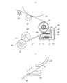
図4は本発明が適用されたクリーニング装置を組み込んだ画像形成装置の実施の形態1を示す。
同図において、符号20は例えば矢印方向に回転する感光体ドラム(潜像担持体)、21は感光体ドラム20を予め帯電するコロトロン等の帯電器、22は各色成分画像情報に基づいて感光体ドラム20上に各色成分に対応した静電潜像を書き込むレーザ走査装置(ROS)などの画像書込装置、23はイエロ(Y)、マゼンタ(M)、シアン(C)及びブラック(K)の各色に対応した現像器23a〜23dが回転ホルダ23eに搭載された回転型(ロータリー型)現像装置であり、感光体ドラム20に形成された静電潜像を現像器23a〜23dのいずれかで現像して各色成分トナー像を形成するようになっている。また、符号25は感光体ドラム20上の残留トナーを廃トナーとして除去するドラムクリーナである。
【0026】
また、符号30は感光体ドラム20の表面に当接されるように配置された中間転写ベルトであり、複数(本実施の形態では例えば6つ)のロール31〜36に張架されて矢印方向へ回動するようになっている。
更に、中間転写ベルト30の感光体ドラム20に対向する部位(一次転写位置)において、中間転写ベルト30の裏面側には一次転写装置(本実施の形態では一次転写ロール)24が配設されており、この一次転写ロール24にトナーの帯電極性と逆極性の電圧を印加することで、感光体ドラム20上のトナー像が中間転写ベルト30に静電吸引されるようになっている。
【0027】
ここで、本実施の形態で用いられる中間転写ベルト30としては、例えばポリイミド樹脂やポリアミド樹脂等の樹脂にカーボンなどの抵抗調整剤を所定量分散し、所定厚に設定されたものが用いられる。
また、中間転写ベルト30の張架ロール31〜36について述べると、符号31は一次転写ロール24による一次転写部位の上流側近傍に設けられる駆動ロール、32は一次転写部位における中間転写ベルト30の姿勢を所定の姿勢に保つために、前記駆動ロール31及び一次転写ロール24の延長線上に配設される従動ロール(姿勢保持ロール)、33は従動ロール32の下流側に設けられて中間転写ベルト30に所定の張力を付与するテンションロール、34,35はテンションロール33の更に下流側に配設される従動ロール、36は後述する二次転写装置40の一要素であるバックアップロール(対向ロール)である。
【0028】
更にまた、用紙などの記録材(図示せず)の搬送経路に面した中間転写ベルト30の二次転写位置には二次転写装置40が配設されており、本実施の形態では、中間転写ベルト30のトナー像担持面側に圧接配置される二次転写ロール41と、中間転写ベルト30の裏面側に配置されて二次転写ロール41の対向電極をなすバックアップロール36とを備えている。
そして、本実施の形態では、例えば二次転写ロール41が接地されており、また、バックアップロール36にはトナーの帯電極性と同極性のバイアスが印加されている。
尚、符号45は二次転写部位へ記録材を案内搬送するガイドシュートである。
【0029】
また、符号50は中間転写ベルト30上の残留トナーを除去するベルトクリーナ(クリーニング装置)である。
本実施の形態において、ベルトクリーナ50は、特に図4及び図5(a)に示すように、中間転写ベルト30のトナー像担持面に対向して開口するクリーナケース53を有し、このクリーナケース53の開口に面して中間転写ベルト30の移動方向上流側から順にウレタンゴム等の弾性ブレード51及びSUS等の金属製スクレーパ52を備えている。
本実施の形態において、弾性ブレード51及び金属製スクレーパ52の取付構造は、クリーナケース53内に揺動アーム54を一端側を揺動支点55として揺動自在に設け、この揺動アーム54の一部にホルダ56を設けると共に、このホルダ56に前記弾性ブレード51及び金属製スクレーパ52の一端部を固定保持し、更に、揺動アーム54の自由端とクリーナケース53との間には復帰スプリング57を介在させ、図示外の駆動機構にて前記揺動アーム54をクリーニング位置とリトラクト位置との間で揺動させるようにしたものである。
尚、図5(a)中、符号58はクリーナケース53の開口下縁に設けられて中間転写ベルト30に弾性的に接触するフィルムシールである。
【0030】
特に、本実施の形態では、弾性ブレード51の各種条件(自由長、接触圧、厚み、セットアングルなど)については、中間転写ベルト30の駆動源に不必要な負荷がかかることなく、清掃性が確保されるという観点から適宜選定される。
一方、金属製スクレーパ52の各種条件についても主として清掃性を確保するという観点から適宜選定されるが、金属製スクレーパ52の先端部での清掃性をより向上させるという観点からすれば、例えば中間転写ベルト30面に当接する先端エッジについてエッチング処理を施すことが好ましい。
更に、弾性ブレード51と金属製スクレーパ52との間隔dについては、クリーナケース53の形状や設定位置等の関係で適宜選定して差し支えない。
但し、両者2枚の間隔dがあまりに近いと経時的にトナーが両者間の隙間に溜まり、清掃性能が低下することがあるため、好ましくは2mm程度以上離間配置することが好ましい。
【0031】
更にまた、本実施の形態では、弾性ブレード51及び金属製スクレーパ52は、張架ロール(駆動ロール)31に対応した中間転写ベルト30部分から中間転写ベルト30の移動方向上流側に外れた近傍位置に配設されており、張架ロール31と中間転写ベルト30との間に浮遊トナーや塵埃が付着し、張架ロール31に対応した中間転写ベルト30表面部分に微小凸部が形成されたとしても、弾性ブレード51及び金属製スクレーパ52の清掃性に影響しないようになっている。
但し、弾性ブレード51については、張架ロール(駆動ロール)31に対応した中間転写ベルト30部分に弾性ブレード51を接触させても差し支えない。
また、本実施の形態では、張架ロール31,36間に位置する中間転写ベルト30の傾斜部に対応してベルトクリーナ50が配設されており、この中間転写ベルト30の傾斜部表面に弾性ブレード51及び金属製スクレーパ52を接触させるために、上流側の弾性ブレード51が下流側の金属製スクレーパ52よりも長い寸法に形成されている。
このため、ベルトユニットに対し、ベルトクリーナ50を交換するような場合でも、金属製スクレーパ52は弾性ブレード51で覆われることになり、交換作業中のユーザが金属製スクレーパ52に触れて怪我をする懸念はない。
【0032】
そして、このベルトクリーナ50は、クリーニングサイクル時には、図示外の駆動機構により前記揺動アーム54をクリーニング位置(リトラクト位置よりも中間転写ベルト30寄りの位置)に移動させ、中間転写ベルト30表面に弾性ブレード51及び金属製スクレーパ52の先端部を所定の接触圧で接触配置する一方、クリーニングサイクル以外、例えば作像サイクル時には、図示外の駆動機構により前記揺動アーム54を復帰スプリング57に抗してリトラクト位置に移動させ、中間転写ベルト30表面から弾性ブレード51及び金属製スクレーパ52の先端部を離間配置するようにしたものである。
【0033】
また、本実施の形態では、例えば平均粒径6μm程度の小径トナーが用いられ、また、トナー像の粒状性向上及び高転写性獲得のため、形状係数(ML2/A)が130以下である球形トナー(本例では重合トナー)である。球形トナーにはクリーニング性、転写性、帯電維持性のため外添剤が添加されている。
前記トナーの形状係数(ML2/A)は次式で示される。
【0034】
【表1】

従って、本実施の形態によれば、弾性ブレード51と金属製スクレーパ52との組合せた態様を用いることで、中間転写ベルト30の駆動源に高い回転トルクを必要とせず、小径あるいは球形トナーの清掃性を向上させると共に、中間転写ベルト30上の微小凸部に対しても安定した清掃性を維持することができる。
これらの作用については後述する実施例にて確認した。
【0036】
◎実施の形態2
図6(a)(b)は本発明に関連する参考発明が適用されたクリーニング装置が組み込まれた画像形成装置の実施の形態2の要部(クリーニング装置周り)を示す。
同図において、画像形成装置の基本的構成は実施の形態1と略同様であり、本実施の形態に係るクリーニング装置は中間転写ベルト30を清掃するベルトクリーナ50に適用されている。尚、実施の形態1と同様な構成要素については実施の形態1と同様な符号を付してここではその詳細な説明を省略する。
このベルトクリーナ50の基本的構成は、実施の形態1と略同様であるが、実施の形態1と異なり、クリーナケース53の開口に面してSUS等の金属製スクレーパ61,62を複数段設けたものである。
この金属製スクレーパ61,62の取付構造は、クリーナケース53内に揺動アーム54を一端側を揺動支点55として揺動自在に設け、この揺動アーム54の一部にホルダ56を設けると共に、このホルダ56に前記複数の金属製スクレーパ61,62の一端部を固定保持し、更に、揺動アーム54の自由端とクリーナケース53との間には復帰スプリング57を介在させ、図示外の駆動機構にて前記揺動アーム54をクリーニング位置とリトラクト位置との間で揺動させるようにしたものである。
【0037】
本実施の形態において、各金属製スクレーパ61,62の各種条件(自由長、接触圧、厚み、セットアングル)については、実施の形態1と同様に、清掃性を良好に確保するという観点から適宜選定され、また、各金属製スクレーパ61,62間の間隔dについては両者間でのトナー溜まりを防止するという観点から、dは2mm以上の適宜間隔に設定される。
また、トナーについては、平均粒径が6μm程度の小径で、形状係数が130以下の球形のものが使用される。
【0038】
特に、本実施の形態では、金属製スクレーパ61,62は、図6(b)に示すように、張架ロール(駆動ロール)31に対応した中間転写ベルト30部分から中間転写ベルト30の移動方向上流側に外れた近傍位置に配設されており、張架ロール31と中間転写ベルト30との間に浮遊トナーや塵埃が付着し、張架ロール31に対応した中間転写ベルト30表面部分に微小凸部が形成されたとしても、各金属製スクレーパ61,62の清掃性に影響しないようになっている。
更に、本実施の形態では、中間転写ベルト30の移動方向に対し、下流側に位置する金属製スクレーパ62が上流側に位置する金属製スクレーパ61よりも低い曲げ剛性に設定されている。例えば自由長を同じに設定し、図6(b)に示すように、各金属製スクレーパ61,62の板厚をt1,t2とすれば、t1>t2の関係を満たすように設定される。
【0039】
従って、本実施の形態によれば、複数段の金属製スクレーパ61,62からなる組合せた態様を用いることで、中間転写ベルト30の駆動源に高い回転トルクを必要とせず、小径あるいは球形トナーの清掃性を向上させると共に、中間転写ベルト30上の微小凸部周辺に対しても安定した清掃性を維持することができる。
ここで、微小凸部周辺の清掃性について補足すると、本例では、複数段の金属製スクレーパ61,62による二つの清掃ポイントを有しており、金属製スクレーパ61,62の中間転写ベルト30と張架ロール31との接触部からの距離をs1,s2とすれば、s1>s2の関係を満たすようになっている。
このため、仮に、中間転写ベルト30上に形成される微小凸部が各金属製スクレーパ61,62部位を通過する際、両金属製スクレーパ61,62の位置関係からして、微小凸部の通過に起因する中間転写ベルト30の変位量が下流側の金属製スクレーパ62による第二の清掃ポイントの方が小さく、その分、微小凸部周辺の清掃性は、上流側の金属製スクレーパ61による第一の清掃ポイントよりも第二の清掃ポイントの方が高く設定される。
これらの作用については後述する実施例にて確認した。
【0040】
◎実施の形態3
図7(a)(b)は本発明に関連する参考発明が適用されたクリーニング装置が組み込まれた画像形成装置の実施の形態3の要部(クリーニング装置周り)を示す。
同図において、画像形成装置の基本的構成は実施の形態2と略同様であり、本実施の形態に係るクリーニング装置は中間転写ベルト30を清掃するベルトクリーナ50に適用されている。尚、実施の形態2と同様な構成要素については実施の形態1と同様な符号を付してここではその詳細な説明を省略する。
このベルトクリーナ50の基本的構成は、実施の形態2と略同様に、クリーナケース53の開口に面してSUS等の金属製スクレーパ61,62を複数段設けたものであるが、実施の形態2と異なり、各金属製スクレーパ61,62に対応する中間転写ベルト30の裏面側にSUS等から裏当てプレート70を接触配設したものである。
この裏当てプレート70としては、金属製スクレーパ61,62が中間転写ベルト30を介して当接したときに変形を生じないものであれば、その材質、厚さ、長さ等は適宜選択してよい。また、設定位置も少なくとも上流側及び下流側の金属製スクレーパ61,62の一方が中間転写ベルト30を介して接触していれば特に限定されるものではない。
【0041】
従って、本実施の形態によれば、複数段の金属製スクレーパ61,62と裏当てプレート70との組合せ態様を用いることで、中間転写ベルト30の駆動源に高い回転トルクを必要とせず、小径あるいは球形トナーの清掃性を向上させると共に、中間転写ベルト30上の微小凸部周辺に対しても安定した清掃性を維持することができる。
特に、本例では、実施の形態2よりも大きな微小凸部周辺のクリーニング性を確保することが可能になる。
これらの作用については後述する実施例にて確認した。
【0042】
【実施例】
◎実施例1
本実施例は、図4及び図5に示す実施の形態1を具体化したモデルである。
本実施例において、中間転写ベルト30はポリイミド樹脂で構成されてカーボンなどの抵抗調整剤を所定量分散配合することによって、体積抵抗率が100V印加時で11logΩcmであるものが用いられる。
また、ベルトクリーナ50内には中間転写ベルト30回転方向上流側に弾性ブレード51及び下流側に金属製スクレーパ52が設置される。
弾性ブレード51は例えば熱硬化性ポリウレタンゴムであり、ゴム硬度77°±3°、23°Cにおける反発弾性36%等の特性をもち、本実施例ではバンドー化学(株)製ハイパーC−1 77が用いられる。
この弾性ブレード51は厚さ2mm、自由長10mmで支持部材(揺動アーム54+ホルダ56)に支持され、中間転写ベルト30とのなす角度を16.5度で保持するようにした。
弾性ブレード51先端の中間転写ベルト30への食い込み量は1.25mmとした。
また、下流側の金属製スクレーパ52は金属製で例えばSUS304等が用いられる。また、金属製スクレーパ52先端の中間転写ベルト30面と当接するエッジについてはクリーニング性能を出すためにエッチング処理が行なわれている。
そして、金属製スクレーパ52の厚みが0.15mm、自由長は10mm、中間転写ベルト30とのなす角度を23度、中間転写ベルト30へは11.9g/mmの圧接力で押し付けられるようになっている。
また、上流側の弾性ブレード51と下流側の金属製スクレーパ52との間隔dは2mmに設定した。
更に、本実施例に用いられるトナーは平均粒径6μmで、形状係数(ML2/A)が130以下である球形トナー(本例では重合トナー)である。
【0043】
以下に本実施例と比較例1,2との間で性能実験を行った結果を示す。
ここで、比較例1はウレタンゴム製の弾性ブレード1枚を用いた態様のクリーニング装置、比較例2はSUS製の金属製スクレーパ1枚を用いた態様のクリーニング装置である。
そして、性能実験として、実施例1及び比較例1,2において、弾性ブレード及び/又は金属製スクレーパを中間転写ベルトへ押圧する力と清掃可能であった中間転写ベルト上の単位面積当たりの重合トナー量との関係を調べたところ、図8に示す実験結果が得られた。
一色当たりの最大トナー量は0.4mg/cm2であるので、Y、M、C、Kの4色を色重ねした場合の最大トナー量は1.6mg/cm2となり、この最大トナー量を清掃することができるのは、弾性ブレードと金属製スクレーパとを組み合わせた実施例1のみであることが確認された。
【0044】
また、本実施例中の弾性ブレード51(本例ではウレタンゴム使用)と金属製スクレーパ52(本例ではSUS使用)とについて、夫々中間転写ベルト30上に形成された微小凸部周辺のクリーニングレベルとの関係を調べたところ、図9に示す結果が得られた。
中間転写ベルト30の製造上の品質管理の観点、及び、使用時中に混入してくると想定される異物の種類から、清掃可能な微小凸部最大高さは50μmであれば問題ない。
金属製スクレーパ52単独では、微少凸部高さが30μmで既に清掃不良が発生してしまうが、弾性ブレード51は微少凸部高さが50μmでも清掃不良が発生しなかった。
【0045】
更に、実施例1において、下流側の金属製スクレーパ52の各種条件(板厚:mm,N.F.[Normal Force]:g/mm,SSA[Scraper Set Angle]:°)を代えて清掃性を調べたところ、図10に示すような結果が得られた。
同図によれば、金属製スクレーパ52の板厚t(図5(b)参照)を厚く設定し、かつ、N.F.を大きく設定すれば、金属製スクレーパ52のSSA(姿勢角度)を大きく設定したとしても、クリーニング性は良好に保たれることが理解される。
【0046】
◎実施例2
本実施例は、図4及び図6に示す実施の形態2を具体化したモデルである。
本実施例において、中間転写ベルト30はポリイミド樹脂で構成されてカーボンなどの抵抗調整剤を所定量分散配合することによって、体積抵抗率が100V印加時で11logΩcmであるものが用いられる。
また、ベルトクリーナ50内には複数段の金属製スクレーパ61,62が設置される。
各金属製スクレーパ61,62は金属製で例えばSUS304等が用いられる。また、金属製スクレーパ61先端の中間転写ベルト30面と当接するエッジについてはクリーニング性能を出すためにエッチング処理が行われている。
本実施例では上流側の金属製スクレーパ61の厚みが0.15mm、下流側の金属製スクレーパ62の厚みが0.05mmで、自由長はどちらも10mmである。また、上流、下流間の金属製スクレーパ61,62間隔は2mmで、各金属製スクレーパ61,62の設定角度は回転方向に対向配置する所謂ドクタ方向で接線に対する角度が各々23°である。
また、本実施例に用いられるトナーは平均粒径6μmで、その形状係数(ML2/A)が130以下である球形トナー(本例では重合トナー)である。
【0047】
以下に本実施例と比較例1,2との間で性能実験1〜3を行った結果を示す。
実験1:
本実施例を用いて高濃度画像転写後のクリーニング性の確認実験を行った。
これは実機で多重色(例えばプロセスブラックや2次色ベタ画像)形成時の転写後や画像形成中の用紙ジャム時、さらに環境等で画像濃度が高く変動した場合等、ベルトクリーナ50に突入するトナーが多いと想定される時にクリーニング性が維持できるかどうかを確認する実験である。
本実施例の実験では、A3用紙2枚連続モードで、プロセスブラックベタ(画像密度300%(=100%×3色))A3全面画像と白紙を送り、1枚目のプロセスブラックでは転写電圧を印加せず、ベルトクリーナ50に中間転写ベルト30上のトナーをすべて突入させ、2枚目の白紙に通常の転写電圧を印加し、前のベタ画像のクリーニング履歴が2枚目の白紙に出るかを確認した。
また、本実験の比較例1,2として、本実施例のベルトクリーナ50をウレタンゴムからなる弾性ブレード(厚さ2mm)1枚に変更したもの(以下ウレタンブレードと記述)と、金属製スクレーパ1枚構成(SUS304/厚さ0.15mm)のもの(以下1枚スクレーパと記述)とを用いて比較した。
これらの実験は通常の実験室環境(22℃/55%RH)の他、高温高湿環境(28℃/85%RH)、低温低湿環境(10℃/15%RH)にても実施した。
【0048】
実験結果を図11に示す。
本実施例においてはすべての環境下でクリーニング不良の発生が見られず、良好なクリーニング性能が示された。一方、比較例1のウレタンブレード、比較例2の1枚スクレーパでは各環境を通じ十分なクリーニング性能が得られず、クリーニング不良が見られた。特にウレタンブレードにおいては幅のある筋状に顕著なクリーニング不良が見られた。
この結果を考察すると、ウレタンブレードにおいてはエッジ先端が弾性的に変形を伴いながらクリーニングを行うため本実施例のような球形トナーを用いると、その間にトナーが進入しやすい。この進入を防ぐために押圧力を強くすると変形量が大きくなるため、ブレードめくれ、泣き等を生じるため必要以上に高い押圧力の設定ができない。また、温度変化等の環境変化に伴い、ウレタンゴムの硬度も変化するため環境変化によりクリーニング性能にばらつきが生じると考えられる。
【0049】
一方、1枚スクレーパにおいては例えば金属により構成されているため、弾性変形がなく球形トナーであっても進入は少ない。また、金属なので温度変化による硬度の変化も少なく、環境下でのクリーニング性能もあまり変化しない。しかし、本実験のように多量のトナー量をクリーニングする場合、一部トナーは金属製スクレーパを通過し筋状のクリーニング不良を生じる。
本実施例のように、上流+下流スクレーパ態様においては、多量のトナーがクリーニング領域に突入して、上流の金属製スクレーパ61を通過するトナーが発生するような場合でも、下流側の金属製スクレーパ62でクリーニングすることができる。また、金属製スクレーパ61,62であるので、上記理由から環境を通して安定したクリーニング性能が得られると考えられる。
【0050】
実験2:
本実施例を用いて中間転写ベルトの凹凸クリーニング性1の確認実験を行った。
これは中間転写ベルト上に実際に微小凸部があるベルトを用い、微小凸部周辺及び微小凸部に起因するクリーニング不良などの発生がないか確認する実験である。
本実験の中間転写ベルトの微小凸部は接触式の3次元測定機で微小凸部高さ約20μm、微小凸部幅約1.5mmと測定された。
微小凸部発生の原因は主にベルト中の気泡などがベルト製造中に発生するものや、経時的にベルト裏面への異物の混入等で裏面から押し出されたり、ベルトの寄りや曲げで発生することも考えられる。
本実験では、A3用紙2枚連続モードで、プロセスブラックベタ(画像密度300%(=100%×3色))A3全面画像と白紙を送り、通常の転写電圧を1枚目、2枚目とも印加し、1枚目のプロセスブラック転写後の微小凸部クリーニングの履歴が2枚目の白紙に出るかを確認した。
また、本実験の比較例としては、実験1と同様に、ウレタンブレード(比較例1)及び1枚スクレーパ(比較例2)で行い、さらに環境も同様に変更し実験を行った。
【0051】
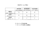
実験結果を図12に示す。
本実施例においてはすべての環境で微小凸部のクリーニング性が良好であった。
また、比較例1のウレタンブレードも同様にすべての環境でクリーニング不良は生じなかったが、比較例2の1枚スクレーパにおいては微小凸部周辺にクリーニング不良は生じた。
この原因として考えられるのは、ウレタンブレードは弾性を持ち微小凸部に沿って密着するため、微小凸部がクリーニング領域を通過してもトナーが通過することなくクリーニングが行われる。一方、1枚スクレーパにおいては、金属は変形しないため、微小凸部にスクレーパが当たると中間転写ベルトが微小凸部の分だけ押圧され下がるため、中間転写ベルトとスクレーパ間に隙間を生じ、結果として微小凸部周辺にクリーニング不良が発生すると考えられる。
本実施例のように、上流+下流スクレーパ態様においては、上流側の金属製スクレーパ61が微小凸部に当たると、中間転写ベルト30は下がり一部トナーは通過するが、下流側の金属製スクレーパ62通過時にも中間転写ベルト30は上流側の金属製スクレーパ61でも押圧されているため、中間転写ベルト30の変位量が少なく、結果として微小凸部周辺のトナーを確実にクリーニングできる。また、金属製スクレーパ61,62の間隔d(図6(b)参照)が十分に空いているため、同時に同一の微小凸部を通過することが無く、安定したクリーニング性能が得られる。
【0052】
実験3:
本実施例を用いて紙粉投入時のクリーニング性の確認実験を行った。
この実験は紙粉等の異物がベルトクリーナに突入した場合のクリーニング性能の確認実験である。
本実験では、予め紙粉を中間転写ベルト上に0.1g散布し、A3用紙2枚連続モードで、マゼンタ色の画像密度60%の単色画像(幅20mm)と白紙を送り、1枚目のマゼンタでは転写電圧を印加せず、ベルトクリーナに中間転写ベルト上のマゼンタトナーをすべて突入させ、2枚目の白紙に通常の転写電圧を印加し、前のマゼンタ画像のクリーニング履歴が2枚目の白紙に出るかを、確認した。
また、本実験の比較例としては、実験1,2同様に、ウレタンブレード(比較例1)及び1枚スクレーパ(比較例2)でも比較実験を行った。
【0053】
実験結果を図13に示す。
本実施例においては紙粉投入時においてもクリーニング不良が発生せず、異物混入時にも良好なクリーニング性を示すことが確認された。比較例1のウレタンブレードも同様にクリーニング性は良好だが、比較例2の1枚スクレーパではクリーニング不良が発生した。
この原因は、本実施例においては画像形成行程を各色4回に渡り行い、中間転写ベルト上の1次転写像を用紙へ一括転写する構成で、ベルトクリーナ50は通常の画像形成時には離間し、一括転写後、所定のタイミングで中間転写ベルト30に当接しクリーニングが行われる。この当接時に紙粉等が存在するとその異物を挟み込み、結果としてその部位に隙間を生じクリーニング不良が生じる。
ウレタンブレードは異物を挟み込んでも弾性的に変形するため、実験2と同様にクリーニング不良を生じない。
本実施例のように、上流+下流スクレーパ態様においては、上流側の金属製スクレーパ61で異物を挟み込み、そこでトナーが通過しても、下流側の金属製スクレーパ62で確実にクリーニングが可能となる。また、下流側の金属製スクレーパ62に異物を挟み込んだ場合でも、上流側の金属製スクレーパ61でクリーニングが行えていればクリーニング不良は発生しないため、長期に渡って安定したクリーニング性能が得られる。
また、金属製スクレーパ61,62は充分な間隔d(図6(b)参照)を持って配置されるため、同一の異物を挟み込むことは無い。
【0054】
◎実施例3
本実施例は、図4及び図7に示す実施の形態3を具体化したモデルであり、基本的に実施例2と同様な構成を有し、更に、各金属製スクレーパ61,62に対応する中間転写ベルト30の裏面側に裏当てプレート70(本例では厚さ2mmのSUS材を使用)を付加したものである。
また、本実施例に用いられるトナーは平均粒径6μmで、その形状係数(ML2/A)が130以下である球形トナー(本例では重合トナー)である。
【0055】
本実施例を用いて以下の実験4,5を行った。
実験4:
本実施例を用いて実験2と同様な中間転写ベルトの凹凸クリーニング性2の確認実験を行った。
実験方法は実験2と同様で詳細な説明は省略する。尚、本実験の中間転写ベルトの微小凸部高さは3次元測定機で約30μm、微小凸部幅約1.5mmと測定されたものを用いる。
通常はこのレベルの微小凸部があるとハーフトーン画像などにも微小凸部に対応して白抜け等で現れ、出荷検査時に不合格品として扱われるが、前記したように経時的に微小凸部が発生する可能性があり、その微小凸部高さは実際に把握されていないため、ストレス条件でのテストではあるが本実験に使用した。
本実施例においては、比較例として、実施例2を使用し、同様に実験を行った。
【0056】
実験結果を図14に示す。
本実施例においてはすべての環境でクリーニング不良が発生せず良好なクリーニング性が得られた。一方、実施例2においては低温低湿環境において微小凸部周辺にクリーニング不良が見られた。
この理由としては、実施例2では実験2で前述したように上流+下流の両方の金属製スクレーパ61,62で押圧されているため、中間転写ベルト30の変位量が少ない状態でクリーニングが行えるが、微小凸部高さが高い場合、この変位量が相対的に増加するために結果として微小凸部周辺に間隙が発生しクリーニング不良が発生してしまうと考えられる。
一方、本実施例においては、中間転写ベルト30の裏面に裏当てプレート70がついているため、この中間転写ベルト30の逃げ量を中間転写ベルト30裏側から抑制でき、結果として高い微小凸部が潰されるようにしてクリーニングが行えるため、微小凸部高さが高い場合でも良好なクリーニング性を発揮すると考えられる。
【0057】
実験5:
本実施例を用いて長期の信頼性実験を行った。
これは写真・文字混合チャートを用いて、各環境で合計30000枚をプリントしクリーニング性の確認を行った。
比較例として1枚スクレーパ(比較例2)のベルトクリーナを用意し同様に実験を行った。
実験結果は、本実施例においては30000枚プリント時にもクリーニング不良は発生しなかった。比較例2の1枚スクレーパにおいては筋状のクリーニング不良が約12000枚プリント時に発生し、約4000枚プリント時には筋状に発生し、その後消える突発的なクリーニング不良も発生した。
これは紙粉等の異物混入が原因と考えられる。また、30000枚プリント終了時に、実験1で行った高濃度画像クリーニング性の実験を行った結果、比較例2の1枚スクレーパでは幅のある筋状のクリーニング不良が複数箇所で発生したが、本実施例においてはクリーニング不良は発生しなかった。よって、本実施例の長期に渡る信頼性が確認された。
【0058】
更に、実施例2、実施例3及び実施例2の下流側金属製スクレーパ62の板厚を変更した変形例(実施例2’,実施例2")について、高濃度画像クリーニング性(実験1)、凹凸クリーニング性1(実験2:低温低湿環境,微小凸部高さ約20μm,微小凸部幅約1.5mm)、凹凸クリーニング性2(実験4:低温低湿環境,微小凸部高さ約30μm,微小凸部幅約1.5mm)、カラー画像の色ずれ性、ベルトユニットの回転負荷トルクを調べたところ、図15に示す結果が得られた。
【0059】
図15によれば、金属製スクレーパの2枚の厚さとディフェクト、画質との関係が把握される。
すなわち、図15のように、高濃度クリーニング性、凹凸クリーニング性1はスクレーパ厚さによらず変わらないが、下流側の金属製スクレーパの厚みを上げていくと、カラー画像の色ずれ量が多くなることがわかった。これは金属製スクレーパを付けた状態でのベルトユニットの回転トルクが、下流側の金属製スクレーパの厚さが増すに伴い増加することから、金属製スクレーパの中間転写ベルトに対する強い押圧力のため、中間転写ベルトの回転負荷が増し、結果として中間転写ベルトの速度変動を引き起こすと考えられる。
従って、本実施例及び変形例の条件の中では下流側の金属製スクレーパの厚さとしては0.05mmが好ましいことが理解される。
しかし、この厚さは特定条件下でのものであり、金属製スクレーパの設定角度、自由長、設定間隔等の条件を調整することで他の厚さのものを選択することも可能であると考えられ、また、特に厚さの条件が、上流側の金属製スクレーパ>下流側の金属製スクレーパ等の制約を受けるものではない。
【0060】
【発明の効果】
以上説明してきたように、本発明によれば、板状クリーニング部材として、移動体の移動方向に対し上流側の弾性クリーニング部材と下流側の非変形クリーニング部材とを組み合わせ、互いに略平行で自由端が移動体の移動方向に対向する方向に向かうようにした態様を用いるようにしたので、小径又は球形の画像形成粒子の清掃性、及び、移動体表面の微小凸部周辺の清掃性を共に改善することができる。
【図面の簡単な説明】
【図1】 (a)は本発明に係るクリーニング装置の概要を示し、(b)は本発明に関連する参考発明に係るクリーニング装置の概要を示す説明図である。
【図2】 (a)は弾性クリーニング部材の小径又は球形の画像形成粒子に対する清掃性を示す説明図、(b)は弾性クリーニング部材の微小凸部周辺の清掃性を示す説明図、(c)は(b)中C−C線方向から見た矢視図である。
【図3】 (a)は非変形クリーニング部材の小径又は球形の画像形成粒子に対する清掃性を示す説明図、(b)は非変形クリーニング部材の微小凸部周辺の清掃性を示す説明図、(c)は移動体がベルト状である態様における(b)中C−C線方向から見た矢視図、(d)はベルト状移動体の裏面に剛体がある態様や移動体自体が剛体である態様における(b)中C−C線方向から見た矢視図である。
【図4】 本発明が適用されたクリーニング装置を組み込んだ画像形成装置の実施の形態1を示す説明図である。
【図5】 (a)は実施の形態1に係るクリーニング装置の詳細を示す説明図、(b)は各クリーニング部材の詳細説明図である。
【図6】 (a)は実施の形態2に係るクリーニング装置の詳細を示す説明図、(b)は各クリーニング部材の詳細説明図である。
【図7】 (a)は実施の形態3に係るクリーニング装置の詳細を示す説明図、(b)は各クリーニング部材の詳細説明図である。
【図8】 実施例1及び比較例1,2の押圧力と清掃可能最大トナー量との関係を示すグラフ図である。
【図9】 実施例1の各クリーニング部材の微小凸部最大高さとクリーニングレベルとの関係を示すグラフ図である。
【図10】 実施例1において、金属製スクレーパの各種条件を振った際のクリーニング性評価結果を示す説明図である。
【図11】 実施例2及び比較例1,2の高濃度画像クリーニング性を示す説明図である。
【図12】 実施例2及び比較例1,2の凹凸クリーニング性1を示す説明図である。
【図13】 実施例2及び比較例1,2の紙粉発生時クリーニング性を示す説明図である。
【図14】 実施例2及び実施例3の凹凸クリーニング性2を示す説明図である。
【図15】 実施例2,実施例3及び実施例2の変形例(実施例2’及び実施例2")における金属製スクレーパの2枚の厚さとディフェクト、画質との関係を示す説明図である。
【符号の説明】
1…移動体,2,2’…画像形成粒子,3…弾性クリーニング部材,4〜6…非変形クリーニング部材,7…対向部材,8…微小凸部,9…微小隙間[0001]
BACKGROUND OF THE INVENTION
The present invention relates to a cleaning device used in an image forming apparatus such as a copying machine or a printer, and more particularly to an improvement of a cleaning device for cleaning image forming particles remaining on a moving body that circulates and an image forming apparatus using the cleaning device. About.
[0002]
[Prior art]
Conventionally, as a cleaning device used in an image forming apparatus such as a copying machine or a printer, for example, an electrophotographic method, an elastic blade such as urethane rubber is applied to the surface of a moving body such as a photosensitive drum or an intermediate transfer belt. Examples thereof include a method of scraping and cleaning toner as image forming particles remaining on the moving body.
[0003]
[Problems to be solved by the invention]
However, in the type using this type of elastic blade, a technical problem has been found that it is difficult to ensure a good cleaning property with respect to toner diameter reduction and spheroidization.
That is, for example, in recent electrophotographic systems, the toner as an image forming material tends to be reduced in diameter and sphere due to a demand for higher image quality. When cleaning with a conventional elastic blade by reducing the diameter of the toner or making it spherical, in order to obtain sufficient cleaning performance, a large force is set to press the elastic blade as a cleaning member against the moving body to be cleaned. There is a need to.
However, elastic blades such as urethane rubber have a large coefficient of friction with the moving body, and if the pressing force is increased, a high rotational torque is required to stably rotate the moving body. This leads to problems such as swelling.
In addition, when the tip shape of the elastic blade is deformed, particularly when the toner is spheroidized, there is a technical problem that the toner slips through the tip of the elastic blade and the cleaning property is remarkably deteriorated.
[0004]
As a means for solving such technical problems, for example, in a moving body such as an intermediate transfer belt using a hard resin such as polyimide resin, a metal scraper (for example, made of SUS) is brought into contact with the surface of the moving body. In addition, there has been proposed one that scrapes and cleans toner as image forming particles remaining on the moving body (for example, Japanese Patent Application No. 2000-278014).
In the type using this type of metal scraper, good cleaning performance can be maintained against the reduction in the diameter and spheroidization of the toner. For example, there is a minute convex portion on the surface of the moving body. In this case, a new technical problem has been found that the cleanability around the minute convex portion tends to be insufficient.
In other words, the case where the minute convex portion is formed on the surface of the moving body is the case where the surface of the moving body itself is rough, the foreign matter adheres to the surface of the moving body, the surface of the moving body is scratched, or the moving body is a belt. It is conceivable that the surface shape is deformed due to the foreign matter sandwiched on the back surface of the moving body.
When this kind of minute convex part passes through the metal scraper, the tip part of the metal scraper is not normally deformed, and the moving body side is deformed, so that the area around the minute convex part of the moving object and the edge part of the metal scraper There is a concern that a minute gap is formed between them, and the toner remaining in the minute gap passes therethrough, resulting in poor cleaning.
[0005]
The present invention has been made in order to solve the above technical problem, and is capable of improving both the cleaning performance of small-diameter or spherical particles and the cleaning performance around the micro-projections on the surface of the moving body. An apparatus and an image forming apparatus using the same are provided.
[0006]
[Means for Solving the Problems]
That is,The present inventionAs shown in FIG. 1A, in the cleaning device for cleaning the
[0007]
In such technical means, the
The
However, the
Further, the
[0008]
Furthermore, as the mounting structure of the
In this case, the degree of elasticity of the “
On the other hand, for the “
For this reason, if the
[0009]
Also, regarding the orientation of the
In addition, various conditions of each
[0010]
The layout of the
For example, in the aspect in which the
On the other hand, in the aspect in which the
[0011]
Further, in the mode in which the moving
In such a case, from the viewpoint of effectively suppressing the influence of the
[0012]
Furthermore, as the material constituting the moving
For example, if annealing is performed in the manufacturing process of a polyimide resin belt, minute convex portions are formed on the belt surface, and the technical problem of slipping through the
[0013]
Here, the operation of the cleaning device of the embodiment shown in FIG.
First, the action of each of the
Now, focusing on the
At this time, the angle formed by the
On the other hand, if the force for pressing the
For this reason, when the
[0014]
Further, paying attention to the
Further, when a rigid body such as a metal such as SUS is used, since the coefficient of friction with the moving
Further, when a rigid body is used for the
[0015]
Next, the cleaning performance around the minute convex portions by the
First, paying attention to the
[0016]
Further, paying attention to the
Note that, in the aspect in which the belt-like moving
[0017]
As described above, it is understood that the
For example, in the embodiment shown in FIG. 1A, the
In this embodiment, most of the
On the other hand, at the first cleaning point P1, when the minute
Further, some of the
Therefore, the small-diameter or spherical image-forming
[0018]
In the layout in which the
[0019]
In addition, the present inventionReference inventions related toAs shown in FIG. 1B, in the cleaning device for cleaning the
In such technical means, the basic configuration of the moving
[0020]
In the embodiment shown in FIG. 1B, various conditions (material,Contact pressure,The set angle, etc.) can be selected as appropriate, but from the standpoint of improving the cleanability.,Located downstream of the moving direction of the moving body 1SecondNon-
Thus, downstreamSecond ofThe bending rigidity of the
[0021]
Moreover, in the aspect which the
In this manner, by adding the facing member 7, the displacement amount of the belt-like moving
[0022]
Here, the operation of the cleaning device of the aspect shown in FIG.
In the embodiment shown in FIG. 1 (b), in the embodiment in which the
However, in the embodiment shown in FIG.First and secondTwo cleaning points P1 and P2 by the
Therefore, in this aspect, most of the
The image-forming
[0023]
For this reason, the minute
Therefore, regardless of whether the small-diameter or spherical image-forming
[0024]
Further, the present invention is shown in FIG.(A)However, the present invention is not limited to the cleaning apparatus shown in FIG.
In this case, the present invention cleans the moving
In particular, since the non-deformable cleaning member 4 (5, 6) is used in the cleaning device of this aspect, it is effective for cleaning the intermediate transfer member.
However, for example, in an embodiment in which the image forming carrier is a hard material such as a dielectric, it can be used for cleaning the image forming carrier.
[0025]
DETAILED DESCRIPTION OF THE INVENTION
Hereinafter, the present invention will be described in detail based on embodiments shown in the accompanying drawings.
FIG. 4 shows
In the figure,
[0026]
Further, a primary transfer device (primary transfer roll in the present embodiment) 24 is disposed on the back side of the
[0027]
Here, as the
Further, the tension rolls 31 to 36 of the
[0028]
Furthermore, a
In this embodiment, for example, the
[0029]
In the present embodiment, the
In this embodiment, the mounting structure of the
In FIG. 5A,
[0030]
In particular, in the present embodiment, with respect to various conditions (free length, contact pressure, thickness, set angle, etc.) of the
On the other hand, various conditions of the
Furthermore, the distance d between the
However, if the distance d between the two sheets is too close, the toner accumulates in the gap between the two over time, and the cleaning performance may be deteriorated.
[0031]
Furthermore, in the present embodiment, the
However, the
Further, in the present embodiment, a
For this reason, even when the
[0032]
In the cleaning cycle, the
[0033]
In this embodiment, for example, a small-diameter toner having an average particle diameter of about 6 μm is used, and a shape factor (ML) is used to improve the granularity of the toner image and acquire high transferability.2/ A) is a spherical toner (polymerized toner in this example) having 130 or less. An external additive is added to the spherical toner for cleaning property, transfer property, and charge maintaining property.
The toner shape factor (ML2/ A) is represented by the following equation.
[0034]
[Table 1]
Therefore, according to the present embodiment, by using a mode in which the
These effects were confirmed in Examples described later.
[0036]
6 (a) and 6 (b) show the present invention.Reference inventions related to5 shows a main part (around the cleaning device) of
In the drawing, the basic configuration of the image forming apparatus is substantially the same as that of the first embodiment, and the cleaning apparatus according to the present embodiment is applied to a
The basic configuration of the
The
[0037]
In the present embodiment, various conditions (free length, contact pressure, thickness, set angle) of the
As the toner, a spherical toner having a small average particle diameter of about 6 μm and a shape factor of 130 or less is used.
[0038]
In particular, in the present embodiment, as shown in FIG. 6B, the
Further, in the present embodiment, the
[0039]
Therefore, according to the present embodiment, a combination of a plurality of stages of
Here, to supplement the cleanability around the minute convex portion, in this example, there are two cleaning points by the
For this reason, when the minute projections formed on the
These effects were confirmed in Examples described later.
[0040]
7 (a) and 7 (b) show the present invention.Reference inventions related to5 shows a main part (around the cleaning device) of
In this figure, the basic configuration of the image forming apparatus is substantially the same as that of the second embodiment, and the cleaning apparatus according to this embodiment is applied to a
The basic configuration of the
As the
[0041]
Therefore, according to the present embodiment, by using the combination of the
In particular, in this example, it is possible to ensure a cleaning property around the micro-projections that is larger than that of the second embodiment.
These effects were confirmed in Examples described later.
[0042]
【Example】
Example 1
This example is a model that embodies the first embodiment shown in FIGS. 4 and 5.
In this embodiment, the
In the
The
This
The amount of biting into the
Further, the
The
The distance d between the upstream
Further, the toner used in this embodiment has an average particle size of 6 μm and a shape factor (ML).2/ A) is a spherical toner (polymerized toner in this example) having 130 or less.
[0043]
The results of performance experiments between this example and Comparative Examples 1 and 2 are shown below.
Here, Comparative Example 1 is a cleaning device using an elastic blade made of urethane rubber, and Comparative Example 2 is a cleaning device using an SUS metal scraper.
As a performance experiment, in Example 1 and Comparative Examples 1 and 2, the force of pressing the elastic blade and / or the metal scraper against the intermediate transfer belt and the polymerized toner per unit area on the intermediate transfer belt that could be cleaned When the relationship with quantity was investigated, the experimental result shown in FIG. 8 was obtained.
The maximum amount of toner per color is 0.4 mg / cm2Therefore, the maximum toner amount when the four colors Y, M, C, and K are overlaid is 1.6 mg / cm.2Thus, it was confirmed that the maximum toner amount can be cleaned only in Example 1 in which an elastic blade and a metal scraper are combined.
[0044]
In addition, for the elastic blade 51 (uses urethane rubber in this example) and the metal scraper 52 (uses SUS in this example) in this embodiment, the cleaning level around the minute projections formed on the
From the viewpoint of quality control in the manufacture of the
With the
[0045]
Furthermore, in Example 1, various conditions (plate thickness: mm, NF [Normal Force]: g / mm, SSA [Scraper Set Angle]: °) for the
According to the figure, the thickness t (see FIG. 5B) of the
[0046]
Example 2
This example is a model that embodies the second embodiment shown in FIGS. 4 and 6.
In this embodiment, the
A plurality of
Each
In this embodiment, the
The toner used in this example has an average particle size of 6 μm and its shape factor (ML2/ A) is a spherical toner (polymerized toner in this example) having 130 or less.
[0047]
Below, the result of having performed the performance experiments 1-3 between a present Example and Comparative Examples 1 and 2 is shown.
Experiment 1:
Using this example, an experiment for confirming the cleaning property after high density image transfer was conducted.
This enters the
In the experiment of the present embodiment, a process black solid (image density 300% (= 100% × 3 colors)) A3 whole image and white paper are sent in the A3 paper two-sheet continuous mode, and the transfer voltage is set for the first process black. Without applying the toner, all the toner on the
Further, as Comparative Examples 1 and 2 of this experiment, the
These experiments were carried out in a normal laboratory environment (22 ° C./55% RH), a high temperature and high humidity environment (28 ° C./85% RH), and a low temperature and low humidity environment (10 ° C./15% RH).
[0048]
The experimental results are shown in FIG.
In this embodiment, no cleaning failure was observed in all environments, and good cleaning performance was shown. On the other hand, with the urethane blade of Comparative Example 1 and the single scraper of Comparative Example 2, sufficient cleaning performance was not obtained through each environment, and defective cleaning was observed. In particular, in the urethane blade, a remarkable cleaning defect was observed in a wide streak shape.
In consideration of this result, in the urethane blade, the edge tip is cleaned while elastically deforming. Therefore, when the spherical toner as in the present embodiment is used, the toner easily enters during that time. If the pressing force is increased in order to prevent this approach, the amount of deformation increases, and blade turning, crying, etc. occur, so that it is not possible to set a pressing force higher than necessary. Further, since the hardness of the urethane rubber changes with environmental changes such as temperature changes, it is considered that the cleaning performance varies due to environmental changes.
[0049]
On the other hand, since the single-sheet scraper is made of, for example, metal, there is no elastic deformation, and even a spherical toner does not enter. Also, since it is a metal, there is little change in hardness due to temperature changes, and the cleaning performance under the environment does not change much. However, when cleaning a large amount of toner as in this experiment, some toner passes through a metal scraper and causes streaky cleaning failure.
As in the present embodiment, in the upstream + downstream scraper mode, even when a large amount of toner enters the cleaning region and toner passing through the
[0050]
Experiment 2:
An experiment for confirming the
This is an experiment in which a belt having a minute convex portion on the intermediate transfer belt is used and whether or not there is a cleaning defect or the like due to the minute convex portion and the vicinity of the minute convex portion.
The minute convex portions of the intermediate transfer belt in this experiment were measured with a contact type three-dimensional measuring machine with a minute convex portion height of about 20 μm and a minute convex portion width of about 1.5 mm.
Causes of micro-projections are mainly caused by bubbles generated in the belt during belt manufacturing, or by being pushed out from the back side due to foreign matter mixed into the back side of the belt over time, or due to deviation or bending of the belt. It is also possible.
In this experiment, a process black solid (image density 300% (= 100% × 3 colors)) A3 whole image and white paper are sent in the A3 paper two-sheet continuous mode, and the normal transfer voltage is applied to both the first and second sheets. Application was performed, and it was confirmed whether or not the history of cleaning the micro-projections after the transfer of the first process black appeared on the second blank sheet.
Further, as a comparative example of this experiment, similarly to
[0051]
The experimental results are shown in FIG.
In this example, the cleaning property of the fine protrusions was good in all environments.
Similarly, the urethane blade of Comparative Example 1 did not cause poor cleaning in all environments, but in the single-sheet scraper of Comparative Example 2, there was a cleaning failure around the minute projections.
A possible reason for this is that the urethane blade has elasticity and is in close contact with the minute projections, so that even if the minute projections pass through the cleaning region, the cleaning is performed without passing the toner. On the other hand, since the metal does not deform in the single-sheet scraper, when the scraper hits the minute projection, the intermediate transfer belt is pressed down by the minute projection, resulting in a gap between the intermediate transfer belt and the scraper. It is considered that a cleaning failure occurs around the minute convex portion.
As in this embodiment, in the upstream + downstream scraper mode, when the
[0052]
Experiment 3:
Using this example, an experiment for confirming the cleaning property at the time of feeding paper dust was conducted.
This experiment is an experiment for confirming the cleaning performance when a foreign substance such as paper dust enters the belt cleaner.
In this experiment, 0.1 g of paper dust was spread on the intermediate transfer belt in advance, and a single-color image (
In addition, as a comparative example of this experiment, a comparative experiment was also conducted with a urethane blade (Comparative Example 1) and a single scraper (Comparative Example 2), as in
[0053]
The experimental results are shown in FIG.
In this example, it was confirmed that no cleaning failure occurred even when paper dust was introduced, and that good cleaning properties were exhibited even when foreign matter was mixed. The urethane blade of Comparative Example 1 was similarly good in cleaning properties, but the single-scraper of Comparative Example 2 had poor cleaning.
In this embodiment, the image forming process is performed four times for each color, and the primary transfer image on the intermediate transfer belt is collectively transferred to the sheet. The
Since the urethane blade is elastically deformed even when a foreign object is inserted, a cleaning failure does not occur as in
As in this embodiment, in the upstream + downstream scraper mode, even if the foreign material is caught by the
Further, since the
[0054]
Example 3
This example is a model that embodies
The toner used in this example has an average particle size of 6 μm and its shape factor (ML2/ A) is a spherical toner (polymerized toner in this example) having 130 or less.
[0055]
The following
Experiment 4:
Using this example, an experiment for confirming the
The experimental method is the same as in
Normally, if there are micro-projections of this level, halftone images appear as white spots corresponding to the micro-projections, and are treated as rejected products at the time of shipping inspection. However, the height of the minute convex portion is not actually grasped, so it was used in this experiment although it was a test under a stress condition.
In this example, Example 2 was used as a comparative example, and an experiment was similarly performed.
[0056]
The experimental results are shown in FIG.
In this example, no cleaning failure occurred in all environments, and good cleaning properties were obtained. On the other hand, in Example 2, in the low temperature and low humidity environment, poor cleaning was observed around the minute convex portion.
The reason for this is that, in Example 2, as described above in
On the other hand, in this embodiment, since the
[0057]
Experiment 5:
A long-term reliability experiment was conducted using this example.
A total of 30,000 sheets were printed in each environment using a photograph / character mixed chart, and the cleaning property was confirmed.
As a comparative example, a belt cleaner of a single scraper (Comparative Example 2) was prepared and an experiment was conducted in the same manner.
As a result of the experiment, in this example, no defective cleaning occurred even when printing 30000 sheets. In the single-sheet scraper of Comparative Example 2, a streaky cleaning failure occurred when printing about 12,000 sheets, a streak occurred when printing about 4000 sheets, and a sudden cleaning failure that disappeared after that occurred.
This is considered to be caused by contamination of foreign matters such as paper dust. Further, as a result of the high density image cleaning performance experiment performed in
[0058]
Further, with respect to the modified examples (Example 2 ′ and Example 2 ″) in which the plate thickness of the
[0059]
According to FIG. 15, the relationship between the thickness of the two metal scrapers, the defect, and the image quality can be grasped.
That is, as shown in FIG. 15, the high density cleaning property and the
Therefore, it is understood that the thickness of the downstream metal scraper is preferably 0.05 mm among the conditions of the present embodiment and the modification.
However, this thickness is under specific conditions, and other thicknesses can be selected by adjusting conditions such as the setting angle, free length, and setting interval of the metal scraper. In addition, the thickness condition is not particularly limited by the upstream metal scraper> the downstream metal scraper.
[0060]
【The invention's effect】
As described above, according to the present invention, as the plate-shaped cleaning member, the elastic cleaning member on the upstream side and the non-deformable cleaning member on the downstream side are combined with respect to the moving direction of the moving body, and the free end is substantially parallel to each other. A mode that is directed in the direction opposite to the moving direction of the moving bodyUseSince this is done, it is possible to improve both the cleanability of small-diameter or spherical image-forming particles and the cleanability around the micro-projections on the surface of the moving body.
[Brief description of the drawings]
[Figure 1](A)Shows an outline of the cleaning device according to the present invention.(B) shows an outline of the cleaning device according to the reference invention related to the present invention.FIG.
FIGS. 2A and 2B are explanatory views showing the cleaning performance of the elastic cleaning member for small-diameter or spherical image-forming particles, FIG. 2B is an explanatory view showing the cleaning performance around the micro-projections of the elastic cleaning member, and FIG. (B) It is the arrow line view seen from the CC line direction.
FIGS. 3A and 3B are explanatory views showing the cleanability of the non-deformable cleaning member with respect to small-diameter or spherical image-forming particles, and FIG. 3B is an explanatory view showing the cleanability of the non-deformable cleaning member around the micro-projections. (c) is an arrow view seen from the direction of the line CC in (b) in the mode in which the moving body is belt-shaped, and (d) is a mode in which the back surface of the belt-shaped moving body has a rigid body or the moving body itself is a rigid body. It is the arrow line view seen from the CC line direction in (b) in a certain aspect.
FIG. 4 is an explanatory
5A is an explanatory view showing details of the cleaning device according to
6A is an explanatory diagram illustrating details of the cleaning device according to the second embodiment, and FIG. 6B is a detailed explanatory diagram of each cleaning member.
7A is an explanatory view showing details of the cleaning device according to
FIG. 8 is a graph showing the relationship between the pressing force and the maximum amount of toner that can be cleaned in Example 1 and Comparative Examples 1 and 2;
FIG. 9 is a graph showing the relationship between the maximum height of minute protrusions and the cleaning level of each cleaning member of Example 1.
FIG. 10 is an explanatory view showing the cleaning performance evaluation results when various conditions of the metal scraper are shaken in Example 1.
FIG. 11 is an explanatory diagram showing high density image cleaning properties of Example 2 and Comparative Examples 1 and 2;
12 is an explanatory view showing the
FIG. 13 is an explanatory diagram showing cleaning properties when paper dust is generated in Example 2 and Comparative Examples 1 and 2.
FIG. 14 is an explanatory view showing the
FIG. 15 is an explanatory diagram showing the relationship between the thickness of two metal scrapers, defects, and image quality in modified examples (Example 2 ′ and Example 2 ″) of Example 2, Example 3 and Example 2; is there.
[Explanation of symbols]
DESCRIPTION OF
Claims (8)
一部が固定されて自由端が移動体の移動方向に対向する方向に向かうように移動体に接触する板状弾性部材であって且つ接触部形状が移動体の移動停止によって変形する弾性クリーニング部材と、
前記弾性クリーニング部材より移動体の移動方向に対し下流側にて一部が固定されて自由端が移動体の移動方向に対向する方向に向かうように当該移動体に接触する板状部材であって、前記弾性クリーニング部材と略平行に配置され且つ接触部形状が移動体の移動停止に拘わらず非変形状態に保たれる非変形クリーニング部材とを備えたことを特徴とするクリーニング装置。In a cleaning device for cleaning image forming particles remaining on a moving body that circulates,
An elastic cleaning member that is a plate-like elastic member that is partly fixed and whose free end is in contact with the moving body so that the free end faces the moving direction of the moving body, and the shape of the contact portion is deformed when the moving body stops moving When,
A plate-like member that contacts the moving body so that a part of the elastic cleaning member is fixed on the downstream side with respect to the moving direction of the moving body and a free end faces a direction opposite to the moving direction of the moving body. And a non-deformable cleaning member which is arranged substantially in parallel with the elastic cleaning member and whose contact portion shape is maintained in an undeformed state regardless of the stoppage of movement of the movable body.
クリーニング対象である移動体が複数の張架ロールに張架されて回動するベルト状移動体であり、
非変形クリーニング部材は、前記ベルト状移動体の張架ロールから外れた近傍位置に配設されていることを特徴とするクリーニング装置。The cleaning device according to claim 1 .
A moving body to be cleaned is a belt-like moving body that rotates by being stretched around a plurality of stretching rolls,
The non-deformable cleaning member is disposed in the vicinity of the belt-like moving body that is out of the stretch roll.
第一の非変形クリーニング部材及び第二の非変形クリーニング部材の配設部位に対応するベルト状移動体の裏面に対向部材を配設したことを特徴とするクリーニング装置。The cleaning device according to claim 2 , wherein
A cleaning device, wherein a counter member is disposed on a back surface of a belt-like moving body corresponding to a portion where the first non-deformable cleaning member and the second non-deformable cleaning member are disposed.
クリーニング対象である移動体は表面がポリイミド樹脂製であることを特徴とするクリーニング装置。The cleaning device according to claim 1 .
A cleaning device characterized in that a moving body to be cleaned has a surface made of polyimide resin.
非変形クリーニング部材は金属製スクレーパにて構成されていることを特徴とするクリーニング装置。The cleaning device according to claim 1 .
A non-deformable cleaning member is constituted by a metal scraper.
クリーニング対象である画像形成粒子は形状係数が130以下である球形粒子であることを特徴とするクリーニング装置。The cleaning device according to claim 1 .
An image forming particle to be cleaned is a spherical particle having a shape factor of 130 or less.
クリーニング対象である移動体は画像が担持される像担持体の一部を構成する中間転写体であることを特徴とする画像形成装置。The image forming apparatus according to claim 7 .
An image forming apparatus, wherein the movable body to be cleaned is an intermediate transfer member constituting a part of an image carrier on which an image is carried.
Priority Applications (1)
| Application Number | Priority Date | Filing Date | Title |
|---|---|---|---|
| JP2001082853A JP4045397B2 (en) | 2001-03-22 | 2001-03-22 | Cleaning device and image forming apparatus using the same |
Applications Claiming Priority (1)
| Application Number | Priority Date | Filing Date | Title |
|---|---|---|---|
| JP2001082853A JP4045397B2 (en) | 2001-03-22 | 2001-03-22 | Cleaning device and image forming apparatus using the same |
Publications (2)
| Publication Number | Publication Date |
|---|---|
| JP2002278319A JP2002278319A (en) | 2002-09-27 |
| JP4045397B2 true JP4045397B2 (en) | 2008-02-13 |
Family
ID=18938746
Family Applications (1)
| Application Number | Title | Priority Date | Filing Date |
|---|---|---|---|
| JP2001082853A Expired - Fee Related JP4045397B2 (en) | 2001-03-22 | 2001-03-22 | Cleaning device and image forming apparatus using the same |
Country Status (1)
| Country | Link |
|---|---|
| JP (1) | JP4045397B2 (en) |
Families Citing this family (8)
| Publication number | Priority date | Publication date | Assignee | Title |
|---|---|---|---|---|
| JP2005173305A (en) | 2003-12-12 | 2005-06-30 | Konica Minolta Business Technologies Inc | Image forming apparatus and method for forming image |
| JP2008304582A (en) | 2007-06-06 | 2008-12-18 | Fuji Xerox Co Ltd | Image forming apparatus |
| JP4657335B2 (en) * | 2008-09-05 | 2011-03-23 | シャープ株式会社 | Fixing apparatus and image forming apparatus |
| JP5198228B2 (en) * | 2008-11-21 | 2013-05-15 | 京セラドキュメントソリューションズ株式会社 | Image forming apparatus |
| JP2014235312A (en) * | 2013-06-03 | 2014-12-15 | コニカミノルタ株式会社 | Image forming apparatus |
| JP6594068B2 (en) * | 2015-07-02 | 2019-10-23 | キヤノン株式会社 | Image forming apparatus |
| JP6594067B2 (en) * | 2015-07-02 | 2019-10-23 | キヤノン株式会社 | Image forming apparatus |
| JP7528602B2 (en) * | 2020-07-22 | 2024-08-06 | コニカミノルタ株式会社 | Cleaning device and image forming apparatus |
-
2001
- 2001-03-22 JP JP2001082853A patent/JP4045397B2/en not_active Expired - Fee Related
Also Published As
| Publication number | Publication date |
|---|---|
| JP2002278319A (en) | 2002-09-27 |
Similar Documents
| Publication | Publication Date | Title |
|---|---|---|
| US6987944B2 (en) | Cleaning device and image forming apparatus using the cleaning device | |
| US11262673B2 (en) | Image forming apparatus | |
| US12204270B2 (en) | Image forming apparatus with brush that collects material adhered to surface of image bearing member and that includes brush portion including threads having specified thread density | |
| JP2005062280A (en) | Image forming apparatus and image carrier stopping control method | |
| JP2007163708A (en) | Cleaning device and image forming apparatus having the same | |
| JP4045397B2 (en) | Cleaning device and image forming apparatus using the same | |
| CN101373365B (en) | Cleaning device, image forming device and image holder unit | |
| US7305207B2 (en) | Cleaning system | |
| US20030108360A1 (en) | Image forming apparatus | |
| JP6308202B2 (en) | Cleaning device and image forming apparatus | |
| JP4498083B2 (en) | Image forming apparatus | |
| JP2001005359A (en) | Image forming apparatus cleaning device | |
| US7907884B2 (en) | Cleaning member and image forming apparatus | |
| JP4866585B2 (en) | Lubricant coating apparatus, process cartridge having lubricant coating apparatus, and image forming apparatus | |
| KR20240044339A (en) | Image forming apparatus | |
| JP2007057850A (en) | Cleaning device and image forming apparatus | |
| JP2008134555A (en) | Lubricant coating apparatus and image forming apparatus | |
| JP2000181221A (en) | Image forming device | |
| JP7815160B2 (en) | Image forming device | |
| JP2023121972A (en) | image forming device | |
| JP7494564B2 (en) | Image forming device | |
| JP2004045450A (en) | Cleaning device for image forming apparatus | |
| JP2007086321A (en) | Lubricant application / cleaning unit, process cartridge, and image forming apparatus | |
| JP2004191686A (en) | Charger and image forming apparatus | |
| JP2025018760A (en) | Image forming device |
Legal Events
| Date | Code | Title | Description |
|---|---|---|---|
| A621 | Written request for application examination |
Free format text: JAPANESE INTERMEDIATE CODE: A621 Effective date: 20040921 |
|
| A977 | Report on retrieval |
Free format text: JAPANESE INTERMEDIATE CODE: A971007 Effective date: 20070420 |
|
| A131 | Notification of reasons for refusal |
Free format text: JAPANESE INTERMEDIATE CODE: A131 Effective date: 20070425 |
|
| A521 | Written amendment |
Free format text: JAPANESE INTERMEDIATE CODE: A523 Effective date: 20070612 |
|
| A131 | Notification of reasons for refusal |
Free format text: JAPANESE INTERMEDIATE CODE: A131 Effective date: 20070711 |
|
| A521 | Written amendment |
Free format text: JAPANESE INTERMEDIATE CODE: A523 Effective date: 20070824 |
|
| TRDD | Decision of grant or rejection written | ||
| A01 | Written decision to grant a patent or to grant a registration (utility model) |
Free format text: JAPANESE INTERMEDIATE CODE: A01 Effective date: 20071024 |
|
| A61 | First payment of annual fees (during grant procedure) |
Free format text: JAPANESE INTERMEDIATE CODE: A61 Effective date: 20071106 |
|
| FPAY | Renewal fee payment (event date is renewal date of database) |
Free format text: PAYMENT UNTIL: 20101130 Year of fee payment: 3 |
|
| R150 | Certificate of patent or registration of utility model |
Ref document number: 4045397 Country of ref document: JP Free format text: JAPANESE INTERMEDIATE CODE: R150 Free format text: JAPANESE INTERMEDIATE CODE: R150 |
|
| FPAY | Renewal fee payment (event date is renewal date of database) |
Free format text: PAYMENT UNTIL: 20111130 Year of fee payment: 4 |
|
| FPAY | Renewal fee payment (event date is renewal date of database) |
Free format text: PAYMENT UNTIL: 20111130 Year of fee payment: 4 |
|
| FPAY | Renewal fee payment (event date is renewal date of database) |
Free format text: PAYMENT UNTIL: 20121130 Year of fee payment: 5 |
|
| FPAY | Renewal fee payment (event date is renewal date of database) |
Free format text: PAYMENT UNTIL: 20121130 Year of fee payment: 5 |
|
| FPAY | Renewal fee payment (event date is renewal date of database) |
Free format text: PAYMENT UNTIL: 20131130 Year of fee payment: 6 |
|
| LAPS | Cancellation because of no payment of annual fees |