JP4040746B2 - Inkjet plotter / printer - Google Patents
Inkjet plotter / printer Download PDFInfo
- Publication number
- JP4040746B2 JP4040746B2 JP10799398A JP10799398A JP4040746B2 JP 4040746 B2 JP4040746 B2 JP 4040746B2 JP 10799398 A JP10799398 A JP 10799398A JP 10799398 A JP10799398 A JP 10799398A JP 4040746 B2 JP4040746 B2 JP 4040746B2
- Authority
- JP
- Japan
- Prior art keywords
- paper
- recording
- sheet
- path member
- recording surface
- Prior art date
- Legal status (The legal status is an assumption and is not a legal conclusion. Google has not performed a legal analysis and makes no representation as to the accuracy of the status listed.)
- Expired - Fee Related
Links
Images

Landscapes
- Ink Jet (AREA)
- Handling Of Cut Paper (AREA)
- Delivering By Means Of Belts And Rollers (AREA)
- Separation, Sorting, Adjustment, Or Bending Of Sheets To Be Conveyed (AREA)
- Feeding Of Articles By Means Other Than Belts Or Rollers (AREA)
Description
【0001】
【発明の属する技術分野】
本発明はCADホストコンピュータの出力機器として用いられるインクジェット型大型プリンタ即ちプロッタに関する。
【0002】
【従来の技術】
インクジェット式プロッタ(プリンタ)において、プリント時のインク付着により生じる波状のしわ(コックル)によって、印刷媒体がプラテンから浮き上がるのを防止するために、プラテン(ペーパーガイド)の印刷領域にリブを設け、印刷媒体に制御されない曲がりが発生するのを減少するようにした技術が、特開平7−256955号に開示されている。
【0003】
また、用紙送りローラの他に、印字領域で用紙即ち記録媒体が浮かないようにするために、用紙排出方向に紙押さえ用の拍車ローラを設けたインクジェット式プロッタが特開平9−48161号公報に開示されている。
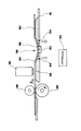
また、図3に示すように、用紙経路部材(2)の記録面より先に駆動装置に連係したサブローラ(4)を設け、このサブローラ(4)と回転自在な拍車ローラ(6)とで用紙を挟持し、サブローラ(4)の周速を、記録ヘッド(10)を基準として、上流側の駆動ローラ(12)の周速よりも少し早くし、駆動ローラ(12)とサブローラ(4)間の用紙にテンションを与えてコックルをなくすようにしたものが知られている。尚、図3中、(14)は加圧ローラである。
【0004】
【課題を解決するための手段】
上記の目的を達成するため、本発明は、駆動ローラ(28)と加圧ローラ(48)とで用紙経路部材(16)の用紙経路面上の用紙の少なくとも両側を挟持し、前記駆動ローラ(28)の回転によって、用紙を、用紙経路部材(16)の記録面(26)の上に搬送し、該記録面(26)上でインクジェット記録ヘッド(36)を用紙を横切る方向に走査して記録を行うようにしたインクジェットプロッタ・プリンタにおいて、前記用紙経路部材(16)の用紙を略水平方向に案内する水平案内部(18a)の記録直後の用紙を案内する部分に凹曲面(56)を形成し、該凹曲面(56)によって前記用紙経路面を前記記録面(26)より低くし且つ該低くした部分(58)の先方を前記記録面(26)と略同等か若しくはそれよりも高く設定するとともに、前記用紙経路部材(16)の記録面(26)より低くした部分にバキューム装置(52)の吸気力を作用させ、前記凹曲面(56)で用紙を湾曲させて用紙にそりを付与するようにしたものである。
【0005】
【課題を解決するための手段】
上記目的を達成するため、本発明は、駆動ローラ(28)と加圧ローラ(48)とで用紙経路部材(16)の用紙経路面上の用紙の少なくとも両側を挾持し、前記駆動ローラ(28)の回転によって、用紙を、用紙経路部材(16)の記録面(26)の上に搬送し、該記録面(26)上でインクジェット記録ヘッド(36)を用紙を横切る方向に走査して記録を行うようにしたインクジェットプロッタにおいて、記録直後の用紙を案内する用紙経路部材(16)の用紙経路面を前記記録面(26)より低くし且つ該低くした部分(58)の先方を前記記録面(26)と略同等か若しくはそれよりも高く設定するとともに、前記用紙経路部材(16)の記録面(26)より低くした部分にバキューム装置(52)の吸気力を作用させ、該低くした部分(58)で用紙を湾曲させて用紙にそりを付与するようにしたものである。
【0006】
【発明の実施の形態】
以下に本発明の実施の形態を、添付した図面を参照して詳細に説明する。
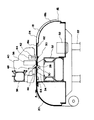
図2において、(16)はインクジェット式プロッタ(大型プリンタ)のプラテン即ち用紙経路部材であり、前部ペーパーガイド(18)と、後部ペーパーガイド(20)とを備えている。前記用紙経路部材(16)は、脚台(22)に支承されている。
【0007】
前記ペーパーガイド(18)(20)は、用紙の幅よりも広い横幅の用紙経路面を有し、用紙経路部材(16)の後方から前方に用紙即ち記録媒体(24)を案内するように配置されている。用紙経路部材(16)の略中央には平坦な記録面(26)が形成され、この記録面(26)の上で印字作画が行われるように構成されている。
【0008】
前記記録面(26)と前記後部ペーパーガイド(20)との対向部の隙間には駆動ローラ(28)が配置され、該駆動ローラ(28)は、駆動軸(30)に取り付けられている。駆動軸(30)は用紙経路部材(16)内の台(32)に固定された軸ホルダ(34)に回転可能に支承され、コントローラにより制御されるXモータに動力伝達機構を介して連結している。(36)はインクジェット式の記録ヘッドであり、図2中、紙面垂直方向即ちY軸に沿って延びる、Y軸ガイドレール(38)に移動自在に取り付けられた担体(40)に取り付けられている。
【0009】
前記担体(40)には、カッタ(42)を昇降可能に保持するカッタヘッド(44)が取り付けられている。前記担体(40)は、コントローラによって制御されるYモータに、前記Y軸ガイドレール(38)に沿って往復動可能に連結している。前記Y軸ガイドレール(38)は、プロッタ本体に架設され、該Y軸ガイドレール(38)に一対の可動ローラホルダ(46)(他方は図示省略)が昇降ガイド(図示省略)を介して、昇降可能に支承されている。
【0010】
前記可動ローラホルダ(46)の各々には加圧ローラ(48)が回転自在に軸支されている。(50)はカットを施行するためのカッタマットであり、Y軸方向に沿って固設されている。(52)はバキューム装置であり、該装置により記録媒体(24)の下面に所定範囲にわたってバキューム力を作用させることができるように構成されている。前記用紙経路部材(16)には、バキューム力を用紙(24)に及ぼすための通気孔(54)が穿設されている。
【0011】
前記前部ペーパーガイド(18)は、ロ−ル用紙(24)を略水平に案内する水平案内部(18a)と、用紙(24)を下方向に案内する屈曲案内部(18b)とから構成され、後部ペーパーガイド(20)も同様に屈曲案内部と水平案内部とが形成されている。前記水平案内部(18a)の記録面(26)の下流に位置する部分には、凹曲面(56)が形成され、該凹曲面(56)の最下部に前記カッターマット(50)が位置している。
【0012】
前記凹曲面(56)により、用紙経路部材(16)の記録直後の位置に、記録面(26)より低くした部分(58)と、これより先方に、記録面(26)と同等か若しくは、それよりも高い部分(60)が形成されている。ペーパーガイド(18)(20)には、駆動軸(30)をはさんで、フロント用紙センサ(62)と、リア用紙センサ(64)が設けられ、これらのセンサ(62)(64)は、ペーパーガイド(18)(20)上の用紙を検出することが出来るように構成されている。
【0013】
次に本実施形態の動作について説明する。
印字作画記録動作がスタートすると、後部ペーパーガイド(20)上に載置セットされたロール紙などの記録媒体(24)は、駆動ローラ(28)と加圧ローラ(48)とでグリップ(挾持)され、記録部材(24)は、この状態で、駆動ローラ(14)の、図1中、時計方向の間欠回転によって、記録面(26)上を、下向きにバキューム力を受けながら、矢方向(A)に搬送される。記録ヘッド(36)は、記録媒体(24)の上を、Y軸方向に往復移動し、記録面(26)上の記録媒体(24)を走査して、記録媒体(24)に記録する。
【0014】
このとき、記録ヘッド(36)のノズルから吐出されるインクによって、記録媒体(24)のインク塗着面にコックル(しわ)が発生する。しかるに、印字作画後の記録媒体(24)は、用紙経路部材(16)の、低くした部分(58)に案内され、ここでバキューム装置(52)の吸気力により吸引され、記録面(26)と低くした部分(58)と高くした部分(60)とによって、弓状に反りが形成される。
【0015】
記録直後の用紙経路部材(16)の凹曲面(56)によって形成された記録媒体(24)の反りにより、記録媒体(24)は平坦な記録面(26)に密着し、記録媒体(24)の記録面(26)上での浮き上がりが阻止される。
【0016】
【発明の効果】
本発明は上述の如く構成したので、簡単な構造によって、記録媒体のコックルの影響を小さくすることができ、高品質の記録を行うことができる。
【図面の簡単な説明】
【図1】本発明の要部の側面断面説明図である。
【図2】プロッタの概略側面断面図である。
【図3】従来技術の説明図である。
【符号の説明】
2 用紙経路部材
4 サブローラ
6 拍車ローラ
8 用紙(記録媒体)
10 記録ヘッド
12 駆動ローラ
14 加圧ローラ
16 用紙経路部材
18 前部ペーパーガイド
20 後部ペーパーガイド
22 脚台
24 記録媒体(用紙)
26 記録面
28 駆動ローラ
30 駆動軸
32 台
34 ホルダ
36 記録ヘッド
40 担体
42 カッタ
44 カッタヘッド
46 ローラホルダ
48 加圧ローラ
50 カッタマット
52 バキューム装置
54 通気孔
56 凹曲面
58 低くした部分
60 高い部分
62 センサ
64 センサ[0001]
BACKGROUND OF THE INVENTION
The present invention relates to an inkjet type large-sized printer or plotter used as an output device of a CAD host computer.
[0002]
[Prior art]
In an inkjet plotter (printer), ribs are provided in the printing area of the platen (paper guide) to prevent the printing medium from floating from the platen due to wavy wrinkles (cockles) generated by ink adhesion during printing. Japanese Patent Laid-Open No. 7-256955 discloses a technique for reducing the occurrence of uncontrolled bending in a medium.
[0003]
In addition to the paper feed roller, an ink jet plotter provided with a spur roller for pressing the paper in the paper discharge direction in order to prevent the paper, that is, the recording medium from floating in the printing area is disclosed in Japanese Patent Laid-Open No. 9-48161. Has been.
Further, as shown in FIG. 3, a sub roller (4) linked to the driving device is provided ahead of the recording surface of the paper path member (2), and the sub roller (4) and the rotatable spur roller (6) are used for paper. And the peripheral speed of the sub roller (4) is slightly faster than the peripheral speed of the upstream drive roller (12) with the recording head (10) as a reference, and between the drive roller (12) and the sub roller (4). A paper is known in which the paper is tensioned to eliminate the cockle. In FIG. 3, reference numeral (14) denotes a pressure roller.
[0004]
[Means for Solving the Problems]
In order to achieve the above object, the present invention sandwiches at least both sides of the sheet on the sheet path surface of the sheet path member (16) by the drive roller (28) and the pressure roller (48), and the drive roller ( 28), the paper is transported onto the recording surface (26) of the paper path member (16) by the rotation of the paper path member (16), and the ink jet recording head (36) is scanned across the recording surface on the recording surface (26). In the ink jet plotter / printer configured to perform recording, a concave curved surface (56) is formed in the portion of the paper path member (16) for guiding the paper immediately after recording of the horizontal guide portion (18a) for guiding the paper in a substantially horizontal direction. The paper path surface is made lower than the recording surface (26) by the concave curved surface (56), and the tip of the lowered portion (58) is substantially equal to or higher than the recording surface (26). Setting Rutotomoni, wherein by applying a suction force of the recording surface vacuum device to lower portion from (26) (52) of the paper path member (16), imparting sled by bending the sheet to the sheet by the concave curved surface (56) It is what you do.
[0005]
[Means for Solving the Problems]
In order to achieve the above object, according to the present invention, the drive roller (28) and the pressure roller (48) sandwich at least both sides of the sheet on the sheet path surface of the sheet path member (16), and the drive roller (28 ), The paper is conveyed onto the recording surface (26) of the paper path member (16), and the inkjet recording head (36) is scanned in the direction across the paper on the recording surface (26) for recording. In the ink jet plotter, the sheet path surface of the sheet path member (16) for guiding the sheet immediately after recording is made lower than the recording surface (26) and the tip of the lowered portion (58) is the recording surface. (26) is set to be substantially equal to or higher than that, and the suction force of the vacuum device (52) is applied to a portion of the paper path member (16) that is lower than the recording surface (26) to reduce the level. By bending the sheet at the portion (58) is obtained so as to impart warping the paper.
[0006]
DETAILED DESCRIPTION OF THE INVENTION
Hereinafter, embodiments of the present invention will be described in detail with reference to the accompanying drawings.
In FIG. 2,
[0007]
The paper guides (18) and (20) have a paper path surface whose width is wider than the width of the paper, and are arranged so as to guide the paper, that is, the recording medium (24) from the rear to the front of the paper path member (16). Has been. A flat recording surface (26) is formed substantially at the center of the paper path member (16), and printing is performed on the recording surface (26).
[0008]
A driving roller (28) is disposed in the gap between the recording surface (26) and the rear paper guide (20), and the driving roller (28) is attached to the driving shaft (30). The drive shaft (30) is rotatably supported by a shaft holder (34) fixed to a table (32) in the paper path member (16), and is connected to an X motor controlled by a controller via a power transmission mechanism. ing. Reference numeral (36) denotes an ink jet recording head, which is attached to a carrier (40) that is movably attached to a Y-axis guide rail (38) extending in the direction perpendicular to the paper surface, that is, along the Y-axis in FIG. .
[0009]
A cutter head (44) for holding the cutter (42) so as to be movable up and down is attached to the carrier (40). The carrier (40) is connected to a Y motor controlled by a controller so as to reciprocate along the Y-axis guide rail (38). The Y-axis guide rail (38) is installed on the plotter body, and a pair of movable roller holders (46) (the other is not shown) are connected to the Y-axis guide rail (38) via a lifting guide (not shown). It is supported so that it can be moved up and down.
[0010]
A pressure roller (48) is rotatably supported on each of the movable roller holders (46). (50) is a cutter mat for enforcing cutting, and is fixed along the Y-axis direction. (52) is a vacuum device, which is configured so that a vacuum force can be applied to the lower surface of the recording medium (24) over a predetermined range. The paper path member (16) has a vent hole (54) for applying a vacuum force to the paper (24).
[0011]
The front paper guide (18) includes a horizontal guide portion (18a) for guiding the roll paper (24) substantially horizontally and a bending guide portion (18b) for guiding the paper (24) downward. The rear paper guide (20) is similarly formed with a bending guide portion and a horizontal guide portion. A concave curved surface (56) is formed in a portion of the horizontal guide portion (18a) located downstream of the recording surface (26), and the cutter mat (50) is located at the bottom of the concave curved surface (56). ing.
[0012]
Due to the concave curved surface (56), a position (58) lower than the recording surface (26) at the position immediately after recording of the paper path member (16) and the recording surface (26) on the further side, or A higher part (60) is formed. The paper guides (18) and (20) are provided with a front paper sensor (62) and a rear paper sensor (64) across the drive shaft (30). These sensors (62) and (64) The paper on the paper guides (18) and (20) can be detected.
[0013]
Next, the operation of this embodiment will be described.
When the printing image recording operation is started, the recording medium (24) such as roll paper placed and set on the rear paper guide (20) is gripped by the driving roller (28) and the pressure roller (48). In this state, the recording member (24) receives a vacuum force downward on the recording surface (26) due to intermittent clockwise rotation of the drive roller (14) in FIG. To A). The recording head (36) reciprocates in the Y-axis direction on the recording medium (24), scans the recording medium (24) on the recording surface (26), and records on the recording medium (24).
[0014]
At this time, the ink ejected from the nozzles of the recording head (36) generates cockle (wrinkles) on the ink-coated surface of the recording medium (24). However, the recording medium (24) after printing is guided to the lowered portion (58) of the paper path member (16), where it is sucked by the suction force of the vacuum device (52), and the recording surface (26). The lowered portion (58) and the raised portion (60) form a bow.
[0015]
The recording medium (24) is in close contact with the flat recording surface (26) due to the warp of the recording medium (24) formed by the concave curved surface (56) of the paper path member (16) immediately after recording, and the recording medium (24). Is prevented from floating on the recording surface (26).
[0016]
【The invention's effect】
Since the present invention is configured as described above, it is possible to reduce the influence of the cockle of the recording medium with a simple structure and to perform high quality recording.
[Brief description of the drawings]
FIG. 1 is a side cross-sectional explanatory view of a main part of the present invention.
FIG. 2 is a schematic side sectional view of a plotter.
FIG. 3 is an explanatory diagram of a prior art.
[Explanation of symbols]
2 Paper path member 4 Sub roller 6 Spur roller 8 Paper (recording medium)
DESCRIPTION OF SYMBOLS 10
26
Claims (1)
Priority Applications (1)
| Application Number | Priority Date | Filing Date | Title |
|---|---|---|---|
| JP10799398A JP4040746B2 (en) | 1998-04-17 | 1998-04-17 | Inkjet plotter / printer |
Applications Claiming Priority (1)
| Application Number | Priority Date | Filing Date | Title |
|---|---|---|---|
| JP10799398A JP4040746B2 (en) | 1998-04-17 | 1998-04-17 | Inkjet plotter / printer |
Publications (2)
| Publication Number | Publication Date |
|---|---|
| JPH11301880A JPH11301880A (en) | 1999-11-02 |
| JP4040746B2 true JP4040746B2 (en) | 2008-01-30 |
Family
ID=14473272
Family Applications (1)
| Application Number | Title | Priority Date | Filing Date |
|---|---|---|---|
| JP10799398A Expired - Fee Related JP4040746B2 (en) | 1998-04-17 | 1998-04-17 | Inkjet plotter / printer |
Country Status (1)
| Country | Link |
|---|---|
| JP (1) | JP4040746B2 (en) |
Families Citing this family (6)
| Publication number | Priority date | Publication date | Assignee | Title |
|---|---|---|---|---|
| JP4070861B2 (en) * | 1998-01-21 | 2008-04-02 | 武藤工業株式会社 | Inkjet printer |
| US6752553B2 (en) * | 2000-12-28 | 2004-06-22 | Seiko Epson Corporation | Recording apparatus |
| DE60233689D1 (en) | 2001-10-17 | 2009-10-22 | Seiko Epson Corp | Transport device for recording medium and inkjet printer |
| US7322690B2 (en) | 2001-10-17 | 2008-01-29 | Seiko Epson Corporation | Fixed material transportation apparatus, liquid fixing apparatus having transporatation apparatus and sucking unit of fixed material in liquid fixing apparatus |
| US20140085390A1 (en) * | 2012-09-27 | 2014-03-27 | Timothy J. Young | Vacuum pulldown of web in printing systems |
| CN107364242B (en) * | 2017-08-25 | 2020-05-08 | 杭州专色数码科技有限公司 | A printing platform for inkjet printing equipment |
-
1998
- 1998-04-17 JP JP10799398A patent/JP4040746B2/en not_active Expired - Fee Related
Also Published As
| Publication number | Publication date |
|---|---|
| JPH11301880A (en) | 1999-11-02 |
Similar Documents
| Publication | Publication Date | Title |
|---|---|---|
| JP4070861B2 (en) | Inkjet printer | |
| JP2784013B2 (en) | Inkjet printer | |
| JPH0948161A (en) | Ink jet recording device | |
| JP2025040789A (en) | Inkjet printer | |
| JP4033250B2 (en) | Inkjet printer | |
| JP4040746B2 (en) | Inkjet plotter / printer | |
| JP5166694B2 (en) | Sheet processing device | |
| JP2011046110A (en) | Inkjet recording device | |
| JP3543208B2 (en) | Paper float prevention mechanism of plotter | |
| JP3965576B2 (en) | Image forming apparatus | |
| JPH05131620A (en) | Hot-melt type ink-jet recording device | |
| JP4117857B2 (en) | Inkjet plotter | |
| JP4399063B2 (en) | Raster plotter | |
| JP4140819B2 (en) | Image forming apparatus | |
| JP2000351499A (en) | Paper feeder for inkjet printer | |
| JP3924366B2 (en) | Plotter | |
| JP2524133B2 (en) | Ink jet recording device | |
| JP2006218807A (en) | Recording device | |
| JP7591481B2 (en) | Inkjet printer | |
| JP4523685B2 (en) | Raster plotter | |
| JP2001058738A (en) | Printing paper transport mechanism | |
| JP2006218806A (en) | Recording device | |
| JP2003118182A (en) | Recording medium transport device and recording device provided with recording medium transport device | |
| JP2003285433A (en) | Liquid injection device | |
| JP3813255B2 (en) | Cutter mechanism for inkjet printer |
Legal Events
| Date | Code | Title | Description |
|---|---|---|---|
| A621 | Written request for application examination |
Free format text: JAPANESE INTERMEDIATE CODE: A621 Effective date: 20050314 |
|
| A977 | Report on retrieval |
Free format text: JAPANESE INTERMEDIATE CODE: A971007 Effective date: 20070411 |
|
| A131 | Notification of reasons for refusal |
Free format text: JAPANESE INTERMEDIATE CODE: A131 Effective date: 20070427 |
|
| A521 | Written amendment |
Free format text: JAPANESE INTERMEDIATE CODE: A523 Effective date: 20070525 |
|
| A711 | Notification of change in applicant |
Free format text: JAPANESE INTERMEDIATE CODE: A712 Effective date: 20070822 |
|
| TRDD | Decision of grant or rejection written | ||
| A01 | Written decision to grant a patent or to grant a registration (utility model) |
Free format text: JAPANESE INTERMEDIATE CODE: A01 Effective date: 20071031 |
|
| A61 | First payment of annual fees (during grant procedure) |
Free format text: JAPANESE INTERMEDIATE CODE: A61 Effective date: 20071108 |
|
| FPAY | Renewal fee payment (event date is renewal date of database) |
Free format text: PAYMENT UNTIL: 20101116 Year of fee payment: 3 |
|
| R150 | Certificate of patent or registration of utility model |
Free format text: JAPANESE INTERMEDIATE CODE: R150 |
|
| FPAY | Renewal fee payment (event date is renewal date of database) |
Free format text: PAYMENT UNTIL: 20111116 Year of fee payment: 4 |
|
| FPAY | Renewal fee payment (event date is renewal date of database) |
Free format text: PAYMENT UNTIL: 20121116 Year of fee payment: 5 |
|
| FPAY | Renewal fee payment (event date is renewal date of database) |
Free format text: PAYMENT UNTIL: 20121116 Year of fee payment: 5 |
|
| S531 | Written request for registration of change of domicile |
Free format text: JAPANESE INTERMEDIATE CODE: R313531 |
|
| FPAY | Renewal fee payment (event date is renewal date of database) |
Free format text: PAYMENT UNTIL: 20121116 Year of fee payment: 5 |
|
| R350 | Written notification of registration of transfer |
Free format text: JAPANESE INTERMEDIATE CODE: R350 |
|
| FPAY | Renewal fee payment (event date is renewal date of database) |
Free format text: PAYMENT UNTIL: 20121116 Year of fee payment: 5 |
|
| FPAY | Renewal fee payment (event date is renewal date of database) |
Free format text: PAYMENT UNTIL: 20131116 Year of fee payment: 6 |
|
| LAPS | Cancellation because of no payment of annual fees |