JP4040743B2 - Water quality maintenance device - Google Patents
Water quality maintenance device Download PDFInfo
- Publication number
- JP4040743B2 JP4040743B2 JP07726398A JP7726398A JP4040743B2 JP 4040743 B2 JP4040743 B2 JP 4040743B2 JP 07726398 A JP07726398 A JP 07726398A JP 7726398 A JP7726398 A JP 7726398A JP 4040743 B2 JP4040743 B2 JP 4040743B2
- Authority
- JP
- Japan
- Prior art keywords
- water
- water quality
- main body
- maintenance device
- factor
- Prior art date
- Legal status (The legal status is an assumption and is not a legal conclusion. Google has not performed a legal analysis and makes no representation as to the accuracy of the status listed.)
- Expired - Fee Related
Links
Images
Landscapes
- Treatment Of Water By Oxidation Or Reduction (AREA)
- Water Treatment By Electricity Or Magnetism (AREA)
Description
【0001】
【発明の属する技術分野】
本発明は、例えば貯水槽内の水を殺菌消毒する水質維持装置に関するものである。
【0002】
【従来の技術】
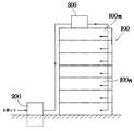
従来、図7に示すように、ビルやマンション等の建築物100 では、浄水場からの上水を地上もしくは地下に配設した受水槽200 よりポンプ等で揚水して屋上に設置した高架水槽300 に貯留し、各部屋100nに給水している。
【0003】
上水は浄水場において0.1ppm以上の残留塩素濃度となるように殺菌消毒されているものの、高架水槽300 内で貯留されている間に残留塩素濃度が水道法規制の0.1ppm未満に低下するおそれがあり、0.1ppm未満の残留塩素濃度では滅菌率が著しく低下するために、高架水槽300 内に雑菌等が繁殖してしまい、使用者の健康を害するおそれがある。
【0004】
そこで、高架水槽300 内において簡易的に殺菌消毒できる水質維持装置が提案され、高架水槽300 内の水質を良好に維持できるようになった。
【0005】
この種の水質維持装置としては、例えば、特公平7−32912号に開示されたものがある。
【0006】
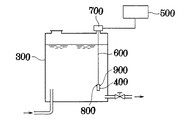
これは、図8に示すように、高架水槽300 内に吊下げられる一対の電極を設けた装置本体400 と、同装置本体400 の電極に電力を供給する駆動制御部500 と、両者を電気的に接続するとともに、吊下げ用ワイヤを兼ねたケーブル600 とを備えている。なお、700 はケーブル600 の中途に設けた吊支用器具である。
【0007】
前記装置本体400 の上部には、水位センサ800 と流速センサ900 とが設けられており、両センサ800,900 は前記ケーブル600 により駆動制御部500 と接続されている。
【0008】
かかる構成により、水位が十分で、水流がないか、あるいはわずかにある場合に、駆動制御部500 は所定時間毎に電力を装置本体400 の電極に一定時間供給して次亜塩素酸を発生させて上水の殺菌消毒を簡便に行うことができる。
【0009】
【発明が解決しようとする課題】
ところが、上記従来の水質維持装置では、次亜塩素酸を発生させる通電タイミングの制御はタイマ等によって所定時間毎に行うだけのものであり、前記水位センサ800 や流速センサ900 は電気分解を行える状態であるかを検出するだけのもので通電タイミングを早めたり遅らせたりする制御には何ら関係していない。
【0010】
これでは、外的要因等で水質が急激に劣化、すなわち残留塩素濃度が急激に低下した場合に対応することができず、残留塩素濃度を適正に維持できないおそれがある。
【0011】
残留塩素濃度は、水温の変化や、原水が滞留しているのか流れているのか等の外的要因によってその減衰にかなりの差があることから、例えば水温センサや水の入れ替わりを検出する手段等の外的要因検出手段を設けて、この検出結果に基づいて通電タイミングを制御すれば、残留塩素濃度の適正値維持の信頼性を高めることができると考えられる。
【0012】
しかし、例えば水温センサを上記した水質維持装置の装置本体400 に取付け、その検出結果を通電タイミングの決定要素としようとすると、装置本体400 の近傍の水温は、装置本体400 自身が通電時に発熱するために若干上昇する傾向にあり、高架水槽300 内を代表する水温としては不適当なものとなり、正確な外的要因の検出にはならないという問題が残る。
【0013】
本発明は、上記課題を解決することのできる水質維持装置を提供することを目的としている。
【0014】
【課題を解決するための手段】
上記課題を解決するために、請求項1記載の本発明では、塩化物を含む原水を貯留した水槽内に、電極を備えた装置本体を配設し、次亜塩素酸を発生させて水質を維持するようにした浸漬式の水質維持装置において、前記電極と水槽外の電源とを連結するケーブルに、水質を劣化させる外的要因を検出する要因検出手段を取付け、同要因検出手段の検出結果に基づいて前記電極への通電タイミングを制御するようにした。したがって、水質の変化を装置本体等からの影響を受けることなく検出できるので水質の変化を確実に検出することができ、水質維持の信頼性が高まる。
【0015】
また、請求項2記載の本発明では、上記要因検出手段を水温センサとし、装置本体から一定距離離隔して配設した。したがって、検出位置が装置本体に対して常に一定距離の位置にあって、検出結果が安定する。
【0018】
【発明の実施の形態】
本発明は、塩化物を含む原水を貯留した水槽内に、一対又は複数対の電極を備えた装置本体を配設し、次亜塩素酸を発生させて水質を維持するようにした浸漬式の水質維持装置において、前記電極と水槽外の電源とを連結するケーブルに、水質を劣化させる外的要因を検出する要因検出手段を取付け、同要因検出手段の検出結果に基づいて前記電極への通電タイミングを制御するようにしたものである。
【0019】
特に、飲料にも供される水槽内の原水は浄水場から送給された浄水であるが、これが劣化するということは、水中の残留塩素濃度が低下することを意味している。そして、かかる残留塩素濃度は、水の滞留時間や水温等の外的要因によってその減衰率が大きく異なることが分かっている。
【0020】
そこで、本発明では、水温センサや流速センサ等の外的要因を検出する要因検出手段と、その検出結果に基づいて電解タイミングを決定する制御部とを具備する構成としており、特に特徴となるのは、前記要因検出手段を、装置本体と水槽外部の電源とを連結するケーブルに取付けたことにある。
【0021】
要因検出手段としては、水質に最も影響を与える水温を監視する水温センサを用いることが好ましく、これをケーブルに取付ける場合、装置本体に近接させるよりも一定距離だけ離隔させることが望ましい。すなわち、装置本体は電極に通電すると熱を発生するので、装置本体近傍では正確な水温を検知できないおそれがあるからである。
【0022】
また、要因検出手段をケーブルに取付ける構成とすれば、水槽の底壁から天井壁に至るまでの間で、好ましい配設位置を適宜容易に決定することができ、しかも、一旦セットすれば、装置本体とセンサとは常に一定の距離だけ離隔した位置にあり、かつこれらを一纏めとして取り扱うことができる。
【0023】
他方、水の滞留状態も水質の劣化を推量する要因とすることができ、これを外的要因とすれば、水温センサに代えて、流速センサや水位センサをケーブルに取付けてもよい。
【0024】
かかる構成により、外的要因の検出結果から水槽中の原水の状態を可及的に正確に検知することができ、この検出結果に基づいて電極への通電タイミングを制御して効率的に次亜塩素酸を発生させ、水槽内の原水を殺菌消毒することができる。
【0025】
また、水の滞留状態を検知するために原水の入れ替わりを検出する手段を用いる場合、前記流速センサや水位センサであればケーブルに取付けることもできるが、その他、配管を流れる水量を検知する流量計や水の流れを検知する超音波センサ、あるいは流れを音として捕らえるマイクロフォンなどを使用することができ、これらは、水槽に連通連結した配管に取付けることが好ましい。あるいは、水槽へ上水を供給するポンプの駆動状態をセンシングするものであっても構わない。
【0026】
このように、水の入れ替わりを監視して、入れ替わりが所定の単位時間内に行われない場合は水が劣化したものとして電極に通電して次亜塩素酸を生成するように制御することができる。
【0027】
また、上記水質維持装置において、通電タイミングを制御する制御部は、電極への通電中及び通電停止後の一定時間は、要因検出手段の作動を停止させるか、あるいは、検出結果を無視するようにすることが好ましい。
【0028】
電極への通電中、すなわち、次亜塩素酸を生成しているときや、生成直後は当然ながら水は殺菌消毒されているので、たとえ水温が上昇したり、丁度滞留時間が所定時間になったとしても、このタイミングで次亜塩素酸を生成すると残留塩素濃度をいたずらに上げるばかりでなく、省電の面からも不利となるからである。
【0029】
このように、本発明は、コンパクトで取り扱いが簡便でありながら、単にタイマーによる時間管理だけでの通電制御に比べて水質の劣化を推量する信頼性が高く、常時適度な残留塩素濃度を維持することができるので、マンションやビルディングの屋上等に設置される高架水槽に適用するに好適である。
【0030】
【実施例】
以下、添付図に基づいて、本発明の実施例を具体的に説明する。
【0031】
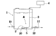
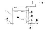
図1は、マンションやビルディングの屋上に設置された高架水槽1を示しており、水道水が貯留されている。10は図示しない受水槽とポンプを介して連通連結した揚水管、11は高架水槽1から伸延させた送水管であり、同送水管11の末端に蛇口等の取水口が取付けられている。12は止水栓である。
【0032】
かかる高架水槽1に本実施例に係る水質維持装置Aが取付けられている。水質維持装置Aは、図示しない一対又は複数対の電極を配設した周知の構成からなる装置本体2と、同装置本体2と電気的に接続され、高架水槽1の外部に設置された制御部4とを具備している。
【0033】
本実施例に係る装置本体2は、脚部20を備えて高架水槽1の底壁に載置した載置型の浸漬式としており、電気ケーブル3を介して前記制御部4と接続されている。前記電極に通電すると、水道水を電気分解して次亜塩素酸を発生させ、水道水の殺菌消毒を行うことができる。
【0034】
制御部4はタイマを備えており、前記電極へ電力を供給するタイミングを制御可能としている。
【0035】
上記構成において、前記電気ケーブル3の中途に外的要因検出手段としての水温センサ5を取付けたことに本発明の特徴がある。
【0036】
本実施例では、水温センサ5を電気ケーブル3に直接取付けるとともに、同電気ケーブル3中の芯線を介して制御部4と電気的に接続しており、取付位置としては、高架水槽1の底部近傍であって、かつ装置本体2から水平方向に一定の距離だけ離隔させている。
【0037】
かかる構成によって、制御部4は水温センサ5の検出結果に基づいて前記電極への通電タイミングを制御し、貯留水の水質を良好な状態に維持することができる。
【0038】
すなわち、水温が高まると、残留塩素濃度の低下が早まるので、電極への通電を開始して次亜塩素酸を生成し、残留塩素濃度を飲料に適する0.2 〜0.4ppm程度の範囲に維持するものである。
【0039】
装置本体2は、通電の際に発熱してその近傍の水温が上昇するものであるが、本実施例では水温センサ5を装置本体2から一定距離だけ離隔して位置させているので、かかる温度上昇を高架水槽1内の水道水全体の温度上昇として誤検出するおそれがなく、本来の水温を正確に検出することができる。したがって、水質維持制御の信頼性が高まっている。
【0040】
また、水質維持装置Aを装置するには、脚部20を下に向けて装置本体2を高架水槽1内に投入し、電気ケーブル3に取付けられた水温センサ5が底部から浮いた状態となるように高架水槽1内の電気ケーブル3長さを調整するだけでよい。
【0041】
以上説明してきたように、本実施例では、電極の通電制御をタイマによる時間管理だけに頼らず、水温上昇という外的要因に基づいて行うようにしいるので、簡単な構成でありながら正確に水質維持を図ることができる。しかも、電気ケーブル3に水温センサ5を取付けているので、纏まりがよく、取り扱いが極めて容易である。
【0042】
(変形例)
以下、第1実施例の変形例について、図2〜図5を参照しながら説明する。
【0043】
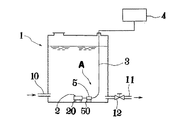
図2に示したものでは、水温センサ5に脚部50を連設し、装置本体2と同様に高架水槽1の底壁に載置している。
【0044】
また、図3に示したものでは、水温センサ5を電気ケーブル3に直接取付けるのではなく、電気ケーブル3から分岐させたセンサ用ケーブル6により吊支している。当然ながら、センサ用ケーブル6の芯線は電気ケーブル3内を通って制御部4と接続している。
【0045】
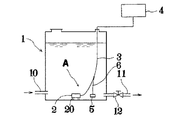
図4に示したものでは、電気ケーブル3が吊支用ワイヤを兼用しており、同電気ケーブル3の下端に装置本体2を、その上方位置に水温センサ5を吊支している。
【0046】
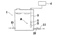
図5に示したものは、図4に示したものとは逆に、電気ケーブル3の下端に水温センサ5を、その上方位置に装置本体2を吊支したものである。
【0047】
図2〜図5のいずれの例においても、水温センサ5は装置本体2から一定距離離隔して配設されることになり、先に説明した効果を奏する。
【0048】
なお、本実施例では、要因検出手段として水温センサ5を用いた例で説明したが、水質を劣化させる要因としては水温以外にも考えられ、例えば、水の滞留時間が一定時間以上になると水質は劣化するので、水が入れ替わる間隔を検出するために、水位センサや流速センサ等を用いることもできる。
【0049】
また、本実施例においては、前記制御部5は、電極への通電中及び通電停止後の一定時間は、水温センサ5等の要因検出手段の作動を停止させるか、あるいは検出結果を無視するようにしている。
【0050】
すなわち、次亜塩素酸を生成しているときや、生成直後は当然ながら水は殺菌消毒されているので、たとえかかる状況下で水温が上昇したり、丁度滞留時間が所定時間になったとしても、このタイミングで改めて次亜塩素酸を生成すると残留塩素濃度をいたずらに上げるばかりでなく、省電の面からも不利となるからである。
【0051】
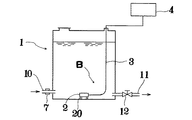
次に、参考例に係る水質維持装置Bについて、図6を参照しながら説明する。なお、第1実施例と同一の構成要素については同一符号で示している。
【0052】
これは、前記要因検出手段を、水の滞留状態を検知するために原水の入れ替わりを検出する手段として流量計7を用いており、電気ケーブル3にではなく、揚水管10の外側に取付けたものである。
【0053】
かかる流量計7で揚水管10内を流れる水量を検出し、単位時間内に所定の水量が高架水槽1内に流入したことを検知しなければ、制御部4は電極に電力を供給するようにしている。
【0054】
また、流量計7に代えて、水の流れを検知する超音波センサや、水流を音として捕らえるマイクロフォンなどを揚水管10に外付けして使用してもよい。なお、当然ながら流量計7等は管内に設けるものであってもよいが、このように、配管外部に取付可能なものを用いれば、水質維持装置Aの設置がより容易となる。あるいは、高架水槽1へ上水を供給するポンプの駆動状態をセンシングするものを用いても構わない。
【0055】
以上、各実施例を通して説明してきたように、本発明に係る水質維持装置A,B を用いれば、外的要因の検出結果から水槽中の原水の状態を可及的に正確に検知することができ、この検出結果に基づいて電極への通電タイミングを制御して効率的に次亜塩素酸を発生させることができるので、単にタイマーによる時間管理だけでの通電制御に比べて高架水槽1内の水をタイミングよく殺菌消毒することができ、常に適度な残留塩素濃度を維持することができる。しかも、コンパクトで取り扱いが簡便なので、マンションやビルディングの屋上等に設置される小規模の高架水槽1等に好適に用いることができる。
【0056】
【発明の効果】
本発明は、上記してきたような形態で実施され、以下の効果を奏する。
【0057】
▲1▼請求項1記載の本発明では、塩化物を含む原水を貯留した水槽内に、電極を備えた装置本体を配設し、次亜塩素酸を発生させて水質を維持するようにした浸漬式の水質維持装置において、前記電極と水槽外の電源とを連結するケーブルに、水質を劣化させる外的要因を検出する要因検出手段を取付け、同要因検出手段の検出結果に基づいて前記電極への通電タイミングを制御するようにしたので、水質の変化を装置本体等からの影響を受けることなく確実に検出することができ、水質維持の信頼性が高まる。また、装置本体と要因検出手段がケーブルを介して一纏まりとなっているので取り扱いが容易となる。
【0058】
▲2▼請求項2記載の本発明では、上記要因検出手段を水温センサとし、装置本体から一定距離離隔して配設したことにより、▲1▼の効果に加え、センサの検出位置が装置本体に対して常に一定距離の位置にあって、検出結果が安定する。
【図面の簡単な説明】
【図1】実施例に係る水質維持装置の説明図である。
【図2】同水質維持装置の変形例を示す説明図である。
【図3】同水質維持装置の変形例を示す説明図である。
【図4】同水質維持装置の変形例を示す説明図である。
【図5】同水質維持装置の変形例を示す説明図である。
【図6】参考例に係る水質維持装置の説明図である。
【図7】建築物の給水設備を示す説明図である。
【図8】従来の水質維持装置の説明図である。
【符号の説明】
A 水質維持装置
1 高架水槽(水槽)
2 装置本体
3 電気ケーブル(ケーブル)
4 制御部
5 水温センサ(要因検出手段)[0001]
BACKGROUND OF THE INVENTION
The present invention relates to a water quality maintenance device that sterilizes and disinfects water in a water tank, for example.
[0002]
[Prior art]
Conventionally, as shown in FIG. 7, in a
[0003]
Water is sterilized and sterilized to have a residual chlorine concentration of 0.1 ppm or more at the water purification plant, but the residual chlorine concentration may be reduced to less than 0.1 ppm of water supply regulations while being stored in the
[0004]
Therefore, a water quality maintenance device that can be easily sterilized and disinfected in the elevated
[0005]
An example of this type of water quality maintenance device is disclosed in Japanese Patent Publication No. 7-32912.
[0006]
As shown in FIG. 8, this is because an apparatus
[0007]
A
[0008]
With this configuration, when the water level is sufficient and there is no or little water flow, the
[0009]
[Problems to be solved by the invention]
However, in the conventional water quality maintenance device, the control of the energization timing for generating hypochlorous acid is only performed at predetermined intervals by a timer or the like, and the
[0010]
In this case, it is impossible to cope with a case where the water quality is rapidly deteriorated due to an external factor or the like, that is, when the residual chlorine concentration is rapidly reduced, and there is a possibility that the residual chlorine concentration cannot be properly maintained.
[0011]
Residual chlorine concentration varies considerably depending on external factors such as changes in water temperature and whether raw water is stagnant or flowing. For example, a water temperature sensor or a means for detecting water changes If the external factor detection means is provided and the energization timing is controlled based on the detection result, it is considered that the reliability of maintaining the appropriate value of the residual chlorine concentration can be improved.
[0012]
However, for example, if a water temperature sensor is attached to the device
[0013]
An object of this invention is to provide the water quality maintenance apparatus which can solve the said subject.
[0014]
[Means for Solving the Problems]
In order to solve the above-mentioned problems, in the present invention according to
[0015]
In the present invention as set forth in
[0018]
DETAILED DESCRIPTION OF THE INVENTION
The present invention is a submersible type in which an apparatus main body including a pair or plural pairs of electrodes is disposed in a water tank storing raw water containing chloride, and hypochlorous acid is generated to maintain water quality. In the water quality maintenance device, a factor detecting means for detecting an external factor that degrades the water quality is attached to a cable that connects the electrode and a power source outside the water tank, and the electrode is energized based on the detection result of the factor detecting means. The timing is controlled.
[0019]
In particular, the raw water in the aquarium used for beverages is purified water supplied from a water purification plant, but the fact that it deteriorates means that the residual chlorine concentration in the water decreases. The residual chlorine concentration has been found to vary greatly in attenuation rate depending on external factors such as the water residence time and water temperature.
[0020]
Therefore, the present invention has a configuration including factor detecting means for detecting external factors such as a water temperature sensor and a flow velocity sensor, and a control unit for determining electrolysis timing based on the detection result, which is particularly characteristic. Is that the factor detecting means is attached to a cable connecting the apparatus main body and a power source outside the water tank.
[0021]
As the factor detecting means, it is preferable to use a water temperature sensor that monitors the water temperature that has the most influence on the water quality. When this sensor is attached to the cable, it is desirable that the sensor is separated from the apparatus main body by a certain distance. That is, since the device body generates heat when the electrode is energized, there is a possibility that the accurate water temperature cannot be detected in the vicinity of the device body.
[0022]
Further, if the factor detecting means is configured to be attached to the cable, a preferable arrangement position can be easily determined as appropriate from the bottom wall to the ceiling wall of the aquarium, and once set, the device The main body and the sensor are always located at a certain distance from each other, and these can be handled as a group.
[0023]
On the other hand, the stagnation state of water can also be a factor for guessing the deterioration of water quality. If this is an external factor, a flow rate sensor or a water level sensor may be attached to the cable instead of the water temperature sensor.
[0024]
With this configuration, it is possible to detect the state of the raw water in the aquarium as accurately as possible from the detection result of the external factor. Chloric acid can be generated and the raw water in the water tank can be sterilized.
[0025]
In addition , when using means for detecting the change of raw water to detect the water retention state, the flow rate sensor can detect the amount of water flowing through the pipe, although it can be attached to the cable if it is the flow rate sensor or the water level sensor. In addition, an ultrasonic sensor that detects the flow of water or a microphone that captures the flow as sound can be used, and these are preferably attached to piping connected to the water tank. Or you may sense the drive state of the pump which supplies clean water to a water tank.
[0026]
In this way, the replacement of water is monitored, and when the replacement is not performed within a predetermined unit time, it can be controlled to generate hypochlorous acid by energizing the electrode as water has deteriorated. .
[0027]
In the water quality maintenance device, the controller for controlling the energization timing may stop the operation of the factor detection means or ignore the detection result for a certain period of time after energization of the electrode and after the energization is stopped. It is preferable to do.
[0028]
During energization of the electrode, that is, when hypochlorous acid is generated or immediately after generation, the water is naturally sterilized, so even if the water temperature rises or the residence time has just reached the specified time However, if hypochlorous acid is generated at this timing, not only the residual chlorine concentration is increased unnecessarily, but also disadvantageous in terms of power saving .
[0029]
As described above, the present invention is compact and easy to handle, but has a higher reliability for estimating the deterioration of water quality than the energization control only by time management by a timer, and always maintains an appropriate residual chlorine concentration. Therefore, it is suitable for application to an elevated water tank installed on the roof of an apartment or building.
[0030]
【Example】
Hereinafter, embodiments of the present invention will be described in detail with reference to the accompanying drawings.
[0031]
FIG. 1 shows an
[0032]
A water quality maintenance device A according to this embodiment is attached to the
[0033]
The apparatus
[0034]
The
[0035]
In the above configuration, the present invention is characterized in that the
[0036]
In this embodiment, the
[0037]
With this configuration, the
[0038]
That is, as the water temperature rises, the decrease in residual chlorine concentration is accelerated, so that energization of the electrode is started to generate hypochlorous acid, and the residual chlorine concentration is maintained in the range of about 0.2 to 0.4 ppm suitable for beverages. It is.
[0039]
The apparatus
[0040]
In order to install the water quality maintenance device A, the device
[0041]
As described above, in this embodiment, it is preferable to control the energization of the electrodes based on an external factor such as a rise in water temperature without relying only on time management by a timer. Can be maintained. Moreover, since the
[0042]
(Modification)
Hereinafter, modified examples of the first embodiment will be described with reference to FIGS.
[0043]
In the case shown in FIG. 2, the
[0044]
3, the
[0045]
In the example shown in FIG. 4, the
[0046]
In the case shown in FIG. 5, the
[0047]
In any of the examples in FIGS. 2 to 5, the
[0048]
In the present embodiment, the example using the
[0049]
In the present embodiment, the
[0050]
In other words, when hypochlorous acid is generated or immediately after generation, the water is naturally sterilized and sterilized, so even if the water temperature rises under such circumstances, or even if the residence time has just reached a predetermined time This is because if hypochlorous acid is generated again at this timing, not only the residual chlorine concentration is unnecessarily increased, but also power saving is disadvantageous.
[0051]
In the following, water quality maintenance device B according to the reference example will be described with reference to FIG. The same constituent elements as those in the first embodiment are denoted by the same reference numerals.
[0052]
This uses the flow meter 7 as the means for detecting the change of the raw water in order to detect the staying state of the water, and the factor detecting means is attached not to the
[0053]
If the flow meter 7 detects the amount of water flowing through the pumping
[0054]
Further, instead of the flow meter 7, an ultrasonic sensor for detecting the flow of water, a microphone for capturing the water flow as sound, or the like may be externally attached to the pumping
[0055]
As described above, as described through the respective embodiments, the use of the water quality maintenance devices A and B according to the present invention can detect the state of raw water in the tank as accurately as possible from the detection result of the external factor. It is possible to control the energization timing to the electrode based on the detection result and efficiently generate hypochlorous acid. Therefore, in the
[0056]
【The invention's effect】
The present invention is implemented in the form as described above, and has the following effects.
[0057]
(1) In the present invention according to
[0058]
(2) In the present invention as set forth in
[Brief description of the drawings]
FIG. 1 is an explanatory view of a water quality maintenance apparatus according to actual施例.
FIG. 2 is an explanatory view showing a modification of the water quality maintenance device.
FIG. 3 is an explanatory view showing a modification of the water quality maintenance device.
FIG. 4 is an explanatory view showing a modification of the water quality maintenance device.
FIG. 5 is an explanatory view showing a modification of the water quality maintenance device.
FIG. 6 is an explanatory diagram of a water quality maintenance device according to a reference example.
FIG. 7 is an explanatory diagram showing a water supply facility for a building.
FIG. 8 is an explanatory diagram of a conventional water quality maintenance device.
[Explanation of symbols]
A Water
2
4
Claims (2)
前記電極と水槽外の電源とを連結するケーブルに、水質を劣化させる外的要因を検出する要因検出手段を取付け、同要因検出手段の検出結果に基づいて前記電極への通電タイミングを制御することを特徴とする水質維持装置。In the water tank that stores the raw water containing chloride, in the submerged water quality maintenance device that arranges the device main body equipped with electrodes and generates hypochlorous acid to maintain the water quality,
The cable connecting the electrode and the power source outside the water tank is attached with a factor detecting means for detecting an external factor that deteriorates the water quality, and the energization timing to the electrode is controlled based on the detection result of the factor detecting means. Water quality maintenance device characterized by.
Priority Applications (1)
| Application Number | Priority Date | Filing Date | Title |
|---|---|---|---|
| JP07726398A JP4040743B2 (en) | 1998-03-25 | 1998-03-25 | Water quality maintenance device |
Applications Claiming Priority (1)
| Application Number | Priority Date | Filing Date | Title |
|---|---|---|---|
| JP07726398A JP4040743B2 (en) | 1998-03-25 | 1998-03-25 | Water quality maintenance device |
Publications (2)
| Publication Number | Publication Date |
|---|---|
| JPH11267650A JPH11267650A (en) | 1999-10-05 |
| JP4040743B2 true JP4040743B2 (en) | 2008-01-30 |
Family
ID=13628967
Family Applications (1)
| Application Number | Title | Priority Date | Filing Date |
|---|---|---|---|
| JP07726398A Expired - Fee Related JP4040743B2 (en) | 1998-03-25 | 1998-03-25 | Water quality maintenance device |
Country Status (1)
| Country | Link |
|---|---|
| JP (1) | JP4040743B2 (en) |
Families Citing this family (2)
| Publication number | Priority date | Publication date | Assignee | Title |
|---|---|---|---|---|
| JP2013103209A (en) * | 2011-11-16 | 2013-05-30 | Shinmaywa Industries Ltd | Water electrolyzing sterilizing apparatus |
| JP2015192968A (en) * | 2014-03-31 | 2015-11-05 | Toto株式会社 | Sanitized water generator |
-
1998
- 1998-03-25 JP JP07726398A patent/JP4040743B2/en not_active Expired - Fee Related
Also Published As
| Publication number | Publication date |
|---|---|
| JPH11267650A (en) | 1999-10-05 |
Similar Documents
| Publication | Publication Date | Title |
|---|---|---|
| KR101726670B1 (en) | Apparatus and method for providing sterilizing water for dental treatments | |
| US6627053B2 (en) | Water treatment device | |
| US4752401A (en) | Water treatment system for swimming pools and potable water | |
| US20130126440A1 (en) | Method and system for managing a reservoir of water requiring recirculation at time intervals | |
| US7993600B2 (en) | Salt dispensing system | |
| US20090261045A1 (en) | Dual generator single power source for tandem pool and spa | |
| JP4259850B2 (en) | Water treatment equipment | |
| JP2001198573A (en) | Device for supplying sterile water | |
| WO2011105533A1 (en) | Air cleaning device having air purification function and operation control method therefor | |
| JP4040743B2 (en) | Water quality maintenance device | |
| CN111344492A (en) | Pump control device, application and system | |
| JP3562631B2 (en) | Salt-added water electrolytic disinfection equipment | |
| KR101840234B1 (en) | Chlorine water electrolysis apparatus capable of regulating chloride dosage and temperature | |
| JP4340181B2 (en) | Potable water supply machine | |
| JPH10182325A (en) | Device for reinforcing sterilization powder of sodium hypochlorite | |
| JP2627258B2 (en) | Electrolytic disinfection equipment for stored water | |
| KR101793245B1 (en) | Dental sterilization water supply device | |
| CN214629186U (en) | Filter equipment for fish bowl | |
| JP3437911B2 (en) | Water quality maintenance device | |
| MX2009010771A (en) | Integral system for disinfecting pool water. | |
| JP4693886B2 (en) | Water treatment equipment | |
| JP2676667B2 (en) | Water tank sterilizer | |
| JPH1076271A (en) | Operation method for maintaining ph of hypochlorous acid sterilizing water generator and hypochlorous acid concentration and hypochlorous acid sterilizing water generator equipped with control means for implementing method | |
| JP4050044B2 (en) | Mineral water generator | |
| JPH0732912B2 (en) | Submersible water disinfectant |
Legal Events
| Date | Code | Title | Description |
|---|---|---|---|
| A621 | Written request for application examination |
Free format text: JAPANESE INTERMEDIATE CODE: A621 Effective date: 20050323 |
|
| A977 | Report on retrieval |
Free format text: JAPANESE INTERMEDIATE CODE: A971007 Effective date: 20070222 |
|
| A131 | Notification of reasons for refusal |
Free format text: JAPANESE INTERMEDIATE CODE: A131 Effective date: 20070717 |
|
| A521 | Written amendment |
Free format text: JAPANESE INTERMEDIATE CODE: A523 Effective date: 20070914 |
|
| TRDD | Decision of grant or rejection written | ||
| A01 | Written decision to grant a patent or to grant a registration (utility model) |
Free format text: JAPANESE INTERMEDIATE CODE: A01 Effective date: 20071009 |
|
| A61 | First payment of annual fees (during grant procedure) |
Free format text: JAPANESE INTERMEDIATE CODE: A61 Effective date: 20071108 |
|
| FPAY | Renewal fee payment (event date is renewal date of database) |
Free format text: PAYMENT UNTIL: 20101116 Year of fee payment: 3 |
|
| R150 | Certificate of patent or registration of utility model |
Free format text: JAPANESE INTERMEDIATE CODE: R150 |
|
| FPAY | Renewal fee payment (event date is renewal date of database) |
Free format text: PAYMENT UNTIL: 20101116 Year of fee payment: 3 |
|
| FPAY | Renewal fee payment (event date is renewal date of database) |
Free format text: PAYMENT UNTIL: 20111116 Year of fee payment: 4 |
|
| LAPS | Cancellation because of no payment of annual fees |