JP4040730B2 - Video display device - Google Patents
Video display device Download PDFInfo
- Publication number
- JP4040730B2 JP4040730B2 JP33410197A JP33410197A JP4040730B2 JP 4040730 B2 JP4040730 B2 JP 4040730B2 JP 33410197 A JP33410197 A JP 33410197A JP 33410197 A JP33410197 A JP 33410197A JP 4040730 B2 JP4040730 B2 JP 4040730B2
- Authority
- JP
- Japan
- Prior art keywords
- optical system
- see
- line
- optical member
- observer
- Prior art date
- Legal status (The legal status is an assumption and is not a legal conclusion. Google has not performed a legal analysis and makes no representation as to the accuracy of the status listed.)
- Expired - Fee Related
Links
- 230000003287 optical effect Effects 0.000 claims description 413
- 238000001514 detection method Methods 0.000 claims description 142
- 210000005252 bulbus oculi Anatomy 0.000 claims description 77
- 230000000007 visual effect Effects 0.000 claims description 40
- 238000003384 imaging method Methods 0.000 claims description 26
- 230000000694 effects Effects 0.000 claims description 13
- 210000001747 pupil Anatomy 0.000 description 13
- 230000009471 action Effects 0.000 description 10
- 230000004075 alteration Effects 0.000 description 9
- 210000001508 eye Anatomy 0.000 description 7
- 239000000853 adhesive Substances 0.000 description 6
- 230000001070 adhesive effect Effects 0.000 description 6
- 210000003128 head Anatomy 0.000 description 4
- 238000005286 illumination Methods 0.000 description 4
- 230000005540 biological transmission Effects 0.000 description 3
- 230000004048 modification Effects 0.000 description 3
- 238000012986 modification Methods 0.000 description 3
- 230000008859 change Effects 0.000 description 2
- 238000010586 diagram Methods 0.000 description 2
- 238000000034 method Methods 0.000 description 2
- 230000008569 process Effects 0.000 description 2
- 238000002834 transmittance Methods 0.000 description 2
- 201000009310 astigmatism Diseases 0.000 description 1
- 239000013256 coordination polymer Substances 0.000 description 1
- 210000004087 cornea Anatomy 0.000 description 1
- 230000006866 deterioration Effects 0.000 description 1
- 230000014509 gene expression Effects 0.000 description 1
- 239000004973 liquid crystal related substance Substances 0.000 description 1
- 210000001525 retina Anatomy 0.000 description 1
Images


Landscapes
- Liquid Crystal (AREA)
- Devices For Indicating Variable Information By Combining Individual Elements (AREA)
Description
【0001】
【発明の属する技術分野】
本発明は、映像表示装置に関し、特に、観察者の頭部又は顔面に保持することを可能にする頭部又は顔面装着式映像表示装置に関する。
【0002】
【従来の技術】
従来、頭部又は顔面装着式映像表示装置(以下、HMDと言う。)の接眼光学系として、3つの光学面からなり、その中の第1面は画像表示素子からの表示光を入射させる屈折面、もう1つの第2面は残りの第3面で反射した光を反射させて第3面へ入射させる反射面、第3面が第1面を透過して入射した光を第2面側へ反射させる反射面と第2面で反射した光を屈折して観察者の眼へ導く屈折面とを兼ねた面であり、その3面により断面が三角形の変形プリズムを構成しているものを用いることが、特開平3−101709号、特開平8−50256号、特開平8−179223号、特開平8−234136号等において提案されている。これらのものは何れも観察者の視線を検出する視線検出機能を備えている。
【0003】
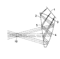
図20は特開平3−101709号による光学系の断面図であり、画像表示素子11から出た表示光はダイクロイックミラー12で反射され、リレーレンズ系13を通り、ビームスプリッター14で反射されて中間像が形成され、その後、第1面16、第2面17、第3面18の3面からなる変形プリズムの接眼光学系15に入射し、観察者眼球Eに画像表示素子11の拡大像を投影するものである。観察者眼球Eの視線を検出するために、赤外光源19が配置され、その照明光は、ダイクロイックミラー12を透過し、リレーレンズ系13を通り、ビームスプリッター14で反射されて中間像が形成され、その後、接眼光学系15の第1面16から入射し、第3面18で全反射され、その後第2面17を透過し、第4面20で反射され、今度は第3面18を通って接眼光学系15から出て観察者眼球Eを照明し、その反射光は上記と逆の順で接眼光学系15を通り、接眼光学系15から出た光は、ビームスプリッター14を透過し、センサー21で検出され、そのセンサー21の反射光の検出位置により視線が検出される。
【0004】
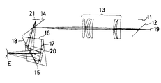
図21は特開平8−50256号による光学系の断面図であり、画像表示素子11から出た表示光は、ダイクロイックミラー面24を有する光学部材23を透過して、第1面16、第2面17、第3面18の3面からなる変形プリズムの接眼光学系15の第1面16から接眼光学系15内に入射し、第3面18で全反射され、その後第2面17で反射され、今度は第3面18を通って接眼光学系15から出て観察者眼球Eに画像表示素子11の拡大像を投影するものである。観察者眼球Eの視線を検出するために、観察者眼球Eを直接照明する赤外光源19が配置され、眼球Eで反射された光は、接眼光学系15の第3面18から接眼光学系15内に入射し、第2面17で反射され、今度は第3面18に入射して全反射され、第1面16を通って接眼光学系15から出て、光学部材23のダイクロイックミラー面24で反射され、光学部材23の接眼光学系15側の面で内部全反射され、結像レンズ25により撮像素子26上に結像し、その撮像素子26上の像から視線が検出される。なお、第2面17は半透過面とし、変形プリズム15の前方に補正プリズム22を配置して、外界を直接観察するシースルーができるようになっている。
【0005】
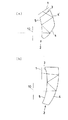
図22は特開平8−179223号による光学系の断面図(a)と正面図(b)であり、画像表示素子11から出た表示光は、第1面16、第2面17、第3面18の3面からなる変形プリズムの接眼光学系15の第1面16から接眼光学系15内に入射し、第3面18で全反射され、その後第2面17で反射され、今度は第3面18を通って接眼光学系15から出て、斜めに傾いたダイクロイックミラー27を透過して観察者眼球Eに画像表示素子11の拡大像を投影するものである。第3面18の法線の中心軸(観察方向)O−Oに対する傾き角θは、20°≦θ≦40°に設定されている。観察者眼球Eの視線を検出するために、観察者眼球Eを直接照明する赤外光源19(19a、19b)が配置され、眼球Eで反射された光は、ダイクロイックミラー27で反射され、結像レンズ25により受光素子26上に結像し、その受光素子26上の像から視線が検出される。
【0006】
図23は特開平8−234136号による光学系の断面図(a)と正面図(b)であり、画像表示素子11から出た表示光は、第1面16、第2面17、第3面18の3面からなる変形プリズムの接眼光学系15の第1面16から接眼光学系15内に入射し、第3面18で全反射され、その後第2面17で反射され、今度は第3面18を通って接眼光学系15から出て観察者眼球Eに画像表示素子11の拡大像を投影するものである。観察者眼球Eの視線を検出するために、観察者眼球Eを直接照明する赤外光源19が配置され、眼球Eで反射された光は、変形プリズムの接眼光学系15の第3面18を透過し、第2面17に設けられた反射膜Mの開口Aを透過し、非点収差を補正するくさびプリズム28を透過して、結像レンズ25により受光素子26上に結像し、その受光素子26上の像から視線が検出される。
【0007】
【発明が解決しようとする課題】
上記の特開平3−101709号のものは、視線検出用光学系と接眼光学系は大部分を共有しているが、接眼光学系全体としてリレー式の光学系であり、光学系が大型化している。また、赤外線で照明された眼の像をセンサー上に結像する場合、光学的パワーを有するのは第4面20のみであるので、センサー21の接眼光学系15からの突出量も大きくなってしまう問題がある。
【0008】
また、特開平8−50256号の実施例1(図21)の場合、画像表示素子と接眼光学系の間隔(working distance)は、収差補正上は狭い方が好ましい。また、接眼光学系の画像表示素子側入射面(第1面)に対して画像表示素子が傾斜しているのが収差補正上好ましい。しかしながら、視線検出のための光学部材23を配置するために、その間隔を大きくする必要が生じ、接眼光学系の収差補正上好ましくない。特に、画像表示素子と接眼光学系の間に光学部材23を挿入すると球面収差が発生するので、これを接眼光学系で補正する必要がある。その結果、視線検出機能のないHMD用の接眼光学系の構成と、視線検出機能付きのHMD用の接眼光学系の構成とが異なるものとなり、2種類の接眼光学系を用意する必要が生じ、コストアップに繋がり好ましくない。なお、実施例5においては、ダイクロイックミラー面を有する光学部材の代わりに、ダイクロイックミラー単体を用いており、接眼光学系の画像表示素子側の間隔拡大、球面収差発生という実施例1の2つの問題点の中、球面収差発生の問題点は関係ない。なお、ダイクロイックミラーを挿入するために、接眼光学系の画像表示素子側の間隔を広げる設計をする必要があるが、広い間隔中にダイクロイックミラーを出し入れすることで、接眼光学系を共有することができる。
【0009】
特開平8−50256号の実施例2のものでは、変形プリズムの接眼光学系の第3面と観察者眼球との間にダイクロイックミラーを配置してその反射光により視線を検出しているが、ある程度の視線検出範囲を確保しようとすると、そのダイクロイックミラーの有効径が大きくなり、その結果、視線検出光学系の顔面側への突出量が増加し、アイリリーフの大きな接眼光学系に変更する必要が生じるという問題がある。
【0010】
特開平8−50256号の実施例3のものでは、接眼光学系の変形プリズム15と補正プリズム22の接合体を平面で2分割し、その間にダイクロイックミラー面を設けてその反射光により視線を検出しているが、接眼光学系を分割すると2分割したプリズムを接着する工程が必要となり、コストアップとなる。また、シースルー機能がない場合には分割しない接眼光学系を使用し、シースルー機能がある場合には分割・接着した接眼光学系を使用することになり、2種類の接眼光学系を用意する必要があり、コストアップに繋がり好ましくない。
【0011】
特開平8−50256号の実施例4のものでは、変形プリズムの接眼光学系の第2面の外側にダイクロイックミラーを配置してその反射光により視線を検出しているが、接眼光学系全体の前方への突出量が大きく増加してしまう。
【0012】
なお、特開平8−50256号の実施例1〜4においては、シースルーを可能にするための補正プリズムに加えて、視線検出を可能にするために光学部材とレンズを付加する必要があり、付加する光学部材の点数が多い問題もある。
【0013】
また、特開平8−179223号においては、変形プリズム15の第3面18の傾き角θを20°≦θ≦40°に設定している。しかし、この条件は好ましくない。その理由を説明する。
【0014】
接眼光学系15の眼球直前の面18の傾斜角θは、視軸O−Oを水平方向に設定した場合、接眼光学系15の収差補正上、及び、接眼光学系15の下部の肉厚を確保しつつ第3面18の全反射条件を満足するためには、5〜25°程度傾斜するのが好ましい。特に15°程度傾斜するのが最も好ましい。
【0015】
すなわち、全反射条件を満足するためには、第3面18は正方向に傾斜し、第2面17はマイナス方向に傾斜するのが好ましい。一方、接眼光学系15の下部の肉厚を確保するためには、第3面18が正方向に傾斜し、第2面17がマイナス方向に傾斜するのは好ましくない。接眼光学系15の下部の肉厚を確保しつつ第3面18の全反射条件を満足するためには、第3面18は垂直方向から5〜25°程度(最も好ましくは、15°程度)傾斜し、第2面17は−2〜−25°程度(最も好ましくは、−12°程度)傾斜するのが好ましい。
【0016】
このようにすると、結果として、接眼光学系15の顔面方向への突出量が少なく好ましい。
ところで、視軸O−Oは下向きにする方が映像を観察しやすいので好ましく、水平方向から0〜−20°程度下向きにするのが好ましい。特に−10°程度が最も好ましい。
【0017】
したがって、HMD装着時には、眼球Eの直前の面18は垂直方向に対して25〜−15°程度傾斜しているのが好ましい。特に10°程度傾斜しているのが最も好ましい。
【0018】
さらに、顔面側への突出量を減少させることを考えると、HMD装着時の眼球Eの直前の面18の傾斜角を20〜−15°程度に限定するのが好ましい。この場合、10°程度傾斜しているのが最も好ましい。
【0019】
したがって、眼球Eの直前の面18が、20°≦視軸に対する角度θ≦40°という条件は好ましくない。
さらに、特開平8−179223号においては、ダイクロイックミラー27で反射後は単レンズ25で受光素子26に結像することしか開示されておらず、これでは顔面側への突出量が大きくなってしまう。その結果、アイリリーフをより大きくする必要が生じ、接眼光学系15を設計する際の制約条件となると共に、接眼光学系15の前方への突出量をより大きくしてしまう問題がある。
【0020】
また、特開平8−234136号のものにおいては、視線検出光学系が妨げとなり、シースルー用の光学部材を追加してもシースルー機能を持たせることができない。
【0021】
本発明は従来技術のこのような問題点に鑑みてなされたものであり、その目的は、接眼光学系に負担をかけることなしに視線検出光学系を一体に構成した頭部装着式映像表示装置に特に適した映像表示装置を提供することである。
【0022】
【課題を解決するための手段】
上記目的を達成する本発明の映像表示装置は、映像を表示する画像表示素子と、前記画像表示素子に表示された映像を観察者眼球に導く反射作用を持つ面を少なくとも1面有する接眼光学系と、観察者眼球の反射光を撮像素子に結像する視線検出光学系とからなる映像表示装置において、
前記視線検出光学系は、少なくとも前記接眼光学系と観察者眼球から出る視線検出光に対して反射作用を持つ前記接眼光学系に接着されたシースルー用光学部材である視線検出用光学部材とから構成され、
前記視線検出光は、前記接眼光学系の反射作用を持つ面を透過後、前記接眼光学系の一部と前記シースルー用光学部材の一部を介して、前記シースルー用光学部材の観察者眼球とは反対側の面で反射した後に、
前記シースルー用光学部材により中間像を形成せずに観察者眼球の像を前記撮像素子上に結像することを特徴とするものである。
【0023】
この映像表示装置は後記の実施例5、6、8〜13が対応する。なお、実施例1〜4、7は本発明の参考例である。このように構成すると、映像表示光を結像する接眼光学系を変更する必要がなく、それに視線検出機能を付加することができる。
【0024】
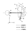
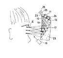
図1は、本発明に基づく映像表示装置の光学系を模式的に示したものである。
まず、本発明において用いる座標系について説明する。観察者の眼球Eの瞳孔10中心を原点とし、観察者眼球Eが画像表示素子1中心を観察しているときの軸上主光線の方向である視軸方向であって、瞳孔10から接眼光学系(変形プリズム)2に向かう方向を正とするZ軸、この視軸に直交し、観察者眼球Eから見て上下方向の下から上を正とするY軸、視軸に直交し、観察者眼球Eから見て左右方向の右から左を正とするX軸を定義する。Y軸を水平方向、X軸を垂直方向に配置してももちろんよい。
【0025】
本発明に基づく映像表示装置は、代表的には、3つの光学面3、4、5からなり、その中の第1面3は画像表示素子1からの表示光を入射させる屈折面、もう1つの第2面4は残りの第3面5で全反射した光を反射させて第3面5へ入射させる反射面、第3面5が第1面3を透過して入射した光を第2面4側へ全反射させる反射面と第2面4で反射した光を屈折して観察者の眼Eへ導く屈折面とを兼ねた面であり、その3面3〜5により断面が三角形の変形プリズムを構成しており、全体として正パワーを有する接眼光学系2を含み、この接眼光学系2により画像表示素子1の表示映像を中間像を形成することなく観察者眼球Eに虚像として拡大投影するものである。
【0026】
面の配置としては、上記以外に2面あるいは4面以上からなるものも含まれるが、基本的に1面以上の反射面(図1の場合は、第2面4)を含むものである。そして、視線検出のために、この反射面4を少なくとも視線検出のための光(通常、赤外光を用いる。)を透過する半透過鏡あるいはダイクロイックミラー面とする。そして、図示は省いてあるが、観察者眼球Eを照明する照明光源を配置する。
【0027】
また、本発明に基づき、変形プリズム2の反射面4に視線検出用光学部材6を接着してある。この視線検出用光学部材6は視線検出のための光を反射する作用を有し、図1の場合は、少なくとも視線検出のための赤外光を反射する反射面7が視線検出用光学部材であるプリズム6の一端に設けられている。
【0028】
この視線検出用光学部材6の反射作用により反射された光は、結像光学系8により撮像素子9上に結像され、その撮像素子9上の像から視線が検出される。
このような構成であるので、視線検出用光学部材6の反射による偏向作用により、視線検出光学系の突出量を少なくすることができる。さらに、シースルー用補正プリズム30を接眼光学系2の反射面4側に追加してシースルー機能を持たせる場合に、視線検出用光学部材6の反射による偏向作用により結像光学系8や撮像素子9が接眼光学系2の下方に配置できるので、これらの結像光学系8や撮像素子9が外界観察を妨げないようにできる。また、視線検出用光学部材6を接眼光学系2に接着するので組立が容易である。
【0029】
また、上記の場合、視線検出用光学部材が反射作用と光学パワーを持つことが望ましい。
この映像表示装置は後記の実施例1〜13が対応する。
【0030】
このように構成すると、図1に示したように、視線検出用光学部材6の下面(射出面)に結像光学系8の機能の全てやその機能の一部を持たせれば、新たな光学素子を追加する必要がなくなったり追加する光学素子を少なくでき組立が容易となる。その結果、光学系全体を単純化できるので、顔面に装着するHMDの光学系として好ましく、コストも削減できる。
【0031】
また、視線検出用光学部材による反射作用により、画像表示素子方向とは略反対方向に視線検出光を偏向するようにすることが望ましい。
この映像表示装置は後記の実施例1〜13が対応する。
【0032】
このように構成すると、図1に示したように、接眼光学系2が、偏心(tilt)した面4で画像表示素子1に対する反射作用を持つ場合、接眼光学系2は逆向きの三角形状となる。視線検出光を視線検出光学部材6の反射面による偏向作用により図1の下方向に偏向するようにすれば、視線検出光学部材6は概ね上向きの三角形状になるので、視線検出光学部材6の前方への突出量を少なくすることができる。
【0033】
また、視線検出用光学部材の反射作用を持つ面は、可視光を透過し赤外光を反射するダイクロイック膜によりなることが望ましい。
この映像表示装置は後記の実施例1〜13が対応する。
【0034】
このように構成すると、画像表示素子に表示された映像や外界光の光量低下を招かずに、赤外光による視線検出を行うことができる。
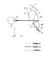
また、視線検出用光学部材がシースルー用光学部材であり、視線検出光学系が、映像観察用の接眼光学系の一部とシースルー用光学部材の一部を介して、シースルー用光学部材の観察者眼球とは反対側の面で反射した後に、撮像素子上に結像することができる。
【0035】
この映像表示装置は後記の実施例5、6、8〜13が対応する。
図2に示すように、変形プリズム2からなる接眼光学系を使用した場合、観察者が外界を観察しようとすると、接眼光学系2のプリズム作用により外界光は偏向されてしまう。そこで、シースルー用光学部材(シースルー用補正プリズム)30により外界光の偏向を補正する必要がある。
【0036】
そして、例えば、シースルー用光学部材30の観察者眼球とは反対側の面31の可視光の透過率を100%、映像観察用の接眼光学系2のシースルー用光学部材30との接合面4の可視光の透過率を50%とすると、画像表示素子1の映像も外界の観察も可能となる。
【0037】
そして、前記の発明が解決しようとする課題の項中で述べたように、接眼光学系2の観察者眼球側の面5は、垂直方向に対して25〜−15°程度傾斜しているのが好ましい(10°程度傾斜しているのが最適)。したがって、シースルー用光学部材30の観察者眼球とは反対側の面31も、接眼光学系2の観察者眼球側の面5と同程度傾斜することになる。
【0038】
このシースルー用光学部材30の観察者眼球とは反対側の面31で反射することで、視線検出光を偏向し、映像観察画角やシースルー画角の外に視線検出光学系を配置することができる。
【0039】
このように、画像表示素子1の映像を観察する光学系に影響を及ぼすことなく、視線検出光学系を構成することができ、視線検出光学系を付加することによる接眼光学系2の仕様低下、収差悪化等がない。また、シースルー機能を損なうことなく、視線検出光学系を構成することができる。
【0040】
図1の場合は、視線検出用光学部材6で視線検出機能を付加し、シースルー用補正プリズム30によりシースルー機能を付加している。接眼光学系2に視線検出機能とシースルー機能の両方を付加する場合、視線検出用光学部材6とシースルー用補正プリズム30を一体化できれば、光学素子の部品点数を削減できるので、コストが削減でき、組立も容易になる。
【0041】
上記の視線検出用光学部材がシースルー用光学部材である場合に、視線検出光の光路が、観察者眼球から接眼光学系の一部を透過し、シースルー用光学部材の一部を透過し、シースルー用光学部材の観察者眼球とは反対側の面で反射し、接眼光学系とシースルー用光学部材との接合面で反射し、結像光学系から撮像素子に達するものとすることができる。
【0042】
この映像表示装置は後記の実施例5、6、8〜12が対応する。
このように視線検出光の光路が2回の反射をすることで、視線検出光学系を顔面側とは反対側に配置できる。そのため、視線検出光学系が顔面側へ突出することで接眼光学系のアイリリーフを必要以上に確保する必要が生じる等の接眼光学系への負担が増加することなく、視線検出光学系を構成することができる。また、2回の反射をすることで、光路を折り畳む効果が得られ、視線検出光学系の突出量が減る。
【0043】
また、視線検出光の光路が、観察者眼球から接眼光学系の一部を透過し、シースルー用光学部材の一部を透過し、シースルー用光学部材の観察者眼球とは反対側の面で反射し、接眼光学系とシースルー用光学部材との接合面で反射し、シースルー用光学部材の観察者眼球とは反対側の面で反射し、結像光学系から撮像素子に達するものとすることができる。
【0044】
この映像表示装置は後記の実施例8、10〜12が対応する。
このように視線検出光の光路が3回の反射をすることで、光路を折り畳む効果がより大きくなり、視線検出光学系の突出量が減る。
【0045】
また、視線検出光学系が、シースルー用光学部材とそれに接合しているプリズムで構成されているものとすることができる。
この映像表示装置は後記の実施例9、11が対応する。
【0046】
視線検出光学系の各面を反射面とレンズからなるように独立した光学素子で構成すると、各光学素子を配置する際に角度や距離の設定を厳密に行う必要がある。しかし、視線検出光学系を1個のプリズムとして一体的に形成し、接眼光学系とシースルー用光学部材とからなる光学部材に接合すれば、組立が容易となり、生産性が向上する。
【0047】
また、本発明の映像表示装置において、視線検出光学系を構成する面の中、少なくとも1面が直交するX方向とY方向で異なる光学作用を有することが望ましい。
【0048】
この映像表示装置は後記の実施例1〜13が対応する。
図1において、接眼光学系2の顔面の直前の面5と反射面4は偏心した光学パワーを持つ面である。また、図2において、シースルー用光学部材30の観察者眼球とは反対側の面31も偏心した光学パワーを持つ面である。視線検出光学系の少なくとも1面が直交するX方向とY方向で異なる光学作用を持つことで、視線検出光が傾斜した光学パワーを持つ面に対して斜めに入射することで発生する偏心収差を補正することができる。
【0049】
【発明の実施の形態】
以下に、本発明の映像表示装置の実施例5、6、8〜13について図7〜図9、図11〜図16を参照して説明する。なお、実施例1〜4、7は本発明の参考例である。
【0050】
ここでは、簡単のために、接眼光学系2や視線検出光学系の光軸は紙面(図3には座標を書き込んであるが、図4〜図16においては省いてある。)のY−Z面内で折り曲げられるものとしているが、X−Z面内で折り曲げてもよい。すなわち、画像表示素子1や視線検出光学系を観察者の上下方向に配置してもよいし、左右方向に配置してもよい。
【0051】
また、前記の発明が解決しようとする課題の項中で述べたように、視軸は水平方向から下向きに設定するのが好ましいが、以下の各実施例では視軸を水平方向に向くものとして設計してある。
〔実施例1〕
図3は、本発明に基づく映像表示装置の実施例1の光学系のY−Z断面であり、接眼光学系を構成する断面が三角形の変形プリズム2は、3つの光学面3、4、5からなり、その間が屈折率1より大きい媒質によって埋められてなり、接眼光学系2の第1面3に面して画像表示素子1が配置され、第3面に面して観察者の眼球の瞳孔10が位置している。画像表示素子1の表示映像を観察するときの光路は、画像表示素子1からの表示光は第1面3で屈折して接眼光学系2内部に入り、第3面で全反射して第2面4に入射し、通常は最も大きな正パワーを有する半透過反射面(シースルー機能を持たない場合は、可視光を反射し、赤外光を透過するダイクロイックミラー面でよい。)の第2面4で反射し、今度は第3面5を透過して接眼光学系2から出て中間像を結像することなく、観察者眼球の瞳孔10に入射して拡大像を網膜上に投影するものである。ここまでの配置は、実施例2〜13も同じであるので、以下の説明においては省く。
【0052】
観察者眼球の視線を検出するには、赤外光を観察者眼球に照射する不図示の赤外光源が観察者眼球の斜め前方等に配置されており(図21〜図23参照)、この照明によって得られる観察者眼球の角膜反射像あるいは瞳孔10の像を撮像素子9によって撮像することにより、視線検出が行われる。以下の実施例1〜13においては、瞳孔10の像を撮像素子9上に結像して視線検出を行うものとするが、角膜反射像あるいはその他の眼球に関する像を撮像素子9によって撮像して視線検出を行うようにすることは容易にできる。
【0053】
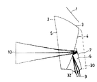
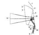
実施例1においては、図3に示すように、接眼光学系2の半透過反射面の第2面4に、視線検出のための赤外光を反射する反射面7を設けた視線検出用光学部材6が接着されており、接眼光学系2の第3面5から入射し、第2面4を通過した視線検出光の光路を、その反射面7により左下方向に偏向させるようにしている。また、視線検出用光学部材6の反射光の出射面32は結像作用を持つ屈折面となっているので、視線検出光はその結像面に配置された撮像素子9上に結像する。このような構成であるので、視線検出用光学部材6の突出量は少なくなっている。
【0054】
ここでは、反射面7を平面としているが、曲率を持たせるとなおよい。さらに、シースルー機能を付加したい場合には、破線で示すシースルー用プリズム30を付加すればよい。この場合も、視線検出用光学部材6や撮像素子9がシースルーを妨げることはない。この場合、視線検出用光学部材6の反射面7は、視線検出光(赤外光)に対して反射作用を持ち、可視光に対しては透過作用を持つ面とする。
〔実施例2〕
図4は、本発明に基づく映像表示装置の実施例2の光学系のY−Z断面であり、実施例1の構成に正レンズ33を追加し、視線検出用光学部材6の出射面32と正レンズ33により、視線検出光を撮像素子9上に結像している。
〔実施例3〕
図5は、本発明に基づく映像表示装置の実施例3の光学系のY−Z断面であり、実施例2の正レンズ33の代わりに正パワーを持った反射プリズム34を使用して、視線検出光学系の下方への突出量を減らしている。
〔実施例4〕
図6は、本発明に基づく映像表示装置の実施例4の光学系のY−Z断面であり、この実施例においては、接眼光学系2の半透過反射面の第2面4に、視線検出のための赤外光を反射する反射面7を設けた視線検出用光学部材6が接着されており、接眼光学系2の第3面5から入射し、第2面4を通過した視線検出光の光路を、その反射面7により左下方向に反射させ、その反射光を視線検出用光学部材6内の第2面4との接着面で再度反射させ視線検出光の光路を右下方向に偏向している例であり、視線検出用光学部材6の反射光の出射面32は結像作用を持つ屈折面となっており、視線検出光はその結像面に配置された撮像素子9上に結像する。このような構成であるので、視線検出用光学部材6の突出量は少なくなっている。
【0055】
さらに、シースルー機能を付加したい場合には、破線で示すシースルー用プリズム30を付加すればよい。この場合も、視線検出用光学部材6や撮像素子9がシースルーを妨げることはない。この場合、視線検出用光学部材6の反射面7は、視線検出光(赤外光)に対して反射作用を持ち、可視光に対しては透過作用を持つ面とする。
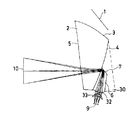
〔実施例5〕
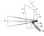
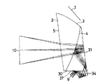
図7は、本発明に基づく映像表示装置の実施例5の光学系のY−Z断面であり、この実施例においては、接眼光学系2の半透過反射面の第2面4に、外界光の偏向を補正するシースルー用光学部材30が接着されており、このシースルー用光学部材30が視線検出用光学部材を兼ねている。接眼光学系2の第3面5から入射し、第2面4を通過した視線検出光の光路は、シースルー用光学部材30の観察者眼球とは反対側の面31により左下方向に反射され、その反射光をシースルー用光学部材30内の第2面4との接着面で再度反射させ、シースルー用光学部材30の右下方向に設けた結像作用を持つ屈折面の出射面35から出射させ、撮像素子9上に結像するようになっている。このような構成であるので、シースルー用光学部材30の突出量は少なくなっている。
【0056】
ここで、シースルー用光学部材30の観察者眼球とは反対側の面31は赤外光を反射するダイクロイックミラー面となっている。この場合、シースルー用光学部材30の下部に視線検出光結像用の面35を加工するだけですむので、光学素子を追加する必要がなく、簡便で小型な視線検出光学系を構成することができる。そして、視線検出光結像用の面35がシースルー用光学部材30の下部にあるので、シースルーを妨げることはない。
【0057】
図7の変形例として、図8に示すように、シースルー用光学部材30の出射面35と撮像素子9の間にミラー36を配置して光路を折り曲げるようにしてもよい。
〔実施例6〕
図9は、本発明に基づく映像表示装置の実施例6の光学系のY−Z断面であり、実施例5の構成に正レンズ(偏心正レンズ)33を追加し、シースルー用光学部材30の出射面35と正レンズ33により、視線検出光を撮像素子9上に結像している。
〔実施例7〕
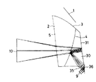
図10は、本発明に基づく映像表示装置の実施例7の光学系のY−Z断面であり、この実施例においては、接眼光学系2の半透過反射面の第2面4に、視線検出のための赤外光を反射する反射面7、7' を設けた視線検出用光学部材6が接着されており、接眼光学系2の第3面5から入射し、第2面4を通過した視線検出光の光路を、視線検出用光学部材6の第1の反射面7により左方向に反射させ、その反射光を視線検出用光学部材6内の第2面4との接着面で再度右下方向へ反射させ、その後視線検出用光学部材6の第2の反射面7' により今度は左下方向に反射させて、視線検出光の光路を左下方向に偏向している例であり、視線検出用光学部材6の反射光の出射面32は結像作用を持つ屈折面となっており、視線検出光はその結像面に配置された撮像素子9上に結像する。この例では、視線検出用光学部材6による3回の反射により光路を折り畳む効果がより大きくなっていると共に、視線検出光の光路を左下方向に偏向しているので、視線検出用光学部材6や撮像素子9の突出量は少なくなっている。
【0058】
さらに、シースルー機能を付加したい場合には、破線で示すシースルー用プリズム30を付加すればよい。この場合も、視線検出用光学部材6や撮像素子9がシースルーを妨げることはない。この場合、視線検出用光学部材6の反射面7、7' は、視線検出光(赤外光)に対して反射作用を持ち、可視光に対しては透過作用を持つ面とする。
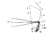
〔実施例8〕
図11は、本発明に基づく映像表示装置の実施例8の光学系のY−Z断面であり、
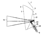
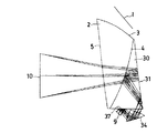
この実施例においては、接眼光学系2の半透過反射面の第2面4に、外界光の偏向を補正するシースルー用光学部材30が接着されており、このシースルー用光学部材30が視線検出用光学部材を兼ねている。接眼光学系2の第3面5から入射し、第2面4を通過した視線検出光の光路は、シースルー用光学部材30の観察者眼球とは反対側の面31により左下方向に反射され、その反射光をシースルー用光学部材30内の第2面4との接着面で再度反射され、その後シースルー用光学部材30の観察者眼球とは反対側の面31により今度は下方向に反射されて、シースルー用光学部材30の下部に設けた結像作用を持つ屈折面の出射面35から出射され、シースルー用光学部材30の出射面35とその出射面35と撮像素子9の間に配置された正レンズ33とにより、視線検出光を撮像素子9上に結像している。
【0059】
この場合も、シースルー用光学部材30の出射面35がシースルー用光学部材30の下部にあるので、シースルーを妨げることはない。
なお、この例では、絞り位置がシースルー用光学部材30の観察者眼球とは反対側の面31での2回目の反射位置と略一致しており、眼球と絞り間距離が確保できているので、視線検出光学系の像側テレセントリック性が良好であり、撮像素子9としてCCD等を使用する際に好適である。
〔実施例9〕
図12は、本発明に基づく映像表示装置の実施例9の光学系のY−Z断面であり、この実施例においては、接眼光学系2の半透過反射面の第2面4に、外界光の偏向を補正するシースルー用光学部材30が接着されており、このシースルー用光学部材30が視線検出用光学部材を兼ねている。接眼光学系2の第3面5から入射し、第2面4を通過した視線検出光の光路は、シースルー用光学部材30の観察者眼球とは反対側の面31により左下方向に反射され、その反射光をシースルー用光学部材30内の第2面4との接着面で再度反射され、シースルー用光学部材30の右下方向に接合した正パワーを持った反射プリズム34の出射面から出射され、撮像素子9上に結像するようになっている。反射プリズム34がシースルー用光学部材30の下部にあるので、シースルーを妨げることはない。また、反射プリズム34は反射面と透過面で構成されており、反射面を使用することで視線検出光の光路を折り曲げ、視線検出光学系の突出量を少なくしている。
〔実施例10〕
図13は、本発明に基づく映像表示装置の実施例10の光学系のY−Z断面であり、実施例8の正レンズ33の代わりに正パワーを持った反射プリズム34を使用して、視線検出光学系の下方への突出量を減らしている。反射プリズム34がシースルー用光学部材30の下部にあるので、シースルーを妨げることはない。また、反射プリズム34は反射面と透過面で構成されており、反射面を使用することで視線検出光の光路を折り曲げ、視線検出光学系の突出量を少なくしている。
〔実施例11〕
図14は、本発明に基づく映像表示装置の実施例11の光学系のY−Z断面であり、この実施例においては、接眼光学系2の半透過反射面の第2面4に、外界光の偏向を補正するシースルー用光学部材30が接着されており、このシースルー用光学部材30が視線検出用光学部材を兼ねている。接眼光学系2の第3面5から入射し、第2面4を通過した視線検出光の光路は、シースルー用光学部材30の観察者眼球とは反対側の面31により左下方向に反射され、その反射光をシースルー用光学部材30内の第2面4との接着面で再度反射され、その後シースルー用光学部材30の観察者眼球とは反対側の面31により今度は下方向に反射されて、シースルー用光学部材30の右下方向に接合した正パワーを持った反射プリズム34の出射面から左上方向へ出射され、その出射光はシースルー用光学部材30の下側の面に設けれた反射面37で反射され、撮像素子9上に結像するようになっている。反射プリズム34がシースルー用光学部材30の下部にあるので、シースルーを妨げることはない。また、反射プリズム34は反射面と透過面で構成されており、反射面を使用することで視線検出光の光路を折り曲げ、また、シースルー用光学部材30の下側の面に設けれた反射面37を介しているので、視線検出光学系の突出量を少なくしている。
〔実施例12〕
図15は、本発明に基づく映像表示装置の実施例12の光学系のY−Z断面であり、実施例11の反射プリズム34を接合せずにシースルー用光学部材30から離して独立させた例である。なお、この例においては、シースルー用光学部材30の下側の射出面は平面で絞り位置と一致している。
【0060】
〔実施例13〕
図15は、本発明に基づく映像表示装置の実施例12の光学系のY−Z断面であり、実施例11の反射プリズム34を接合せずにシースルー用光学部材30から離して独立させた例である。なお、この例においては、シースルー用光学部材30の下側の射出面は平面で絞り位置と一致している。
【0061】
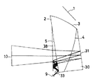
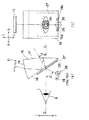
図16は、本発明に基づく映像表示装置の実施例13の光学系のY−Z断面であり、この実施例においては、接眼光学系2の第3面5の観察者眼球側にダイクロイックミラー38が配置され、また、接眼光学系2の半透過反射面の第2面4に、外界光の偏向を補正するシースルー用光学部材30が接着されており、このシースルー用光学部材30が視線検出用光学部材を兼ねている。ダイクロイックミラー38を透過して接眼光学系2の第3面5から入射し、第2面4を通過した視線検出光の光路は、シースルー用光学部材30の観察者眼球とは反対側の面31により左方向に反射され、その反射光は接眼光学系2の第2面4、第3面5を通過してダイクロイックミラー38で反射され、その反射光は今度は接眼光学系2の第3面5で反射され、ダイクロイックミラー38で再度反射され、接眼光学系2の第3面5でもう1度反射されて、正レンズ33により視線検出光を撮像素子9上に結像している。このような構成であるので、視線検出光学系の顔面側への突出量を抑えることができる。
【0062】
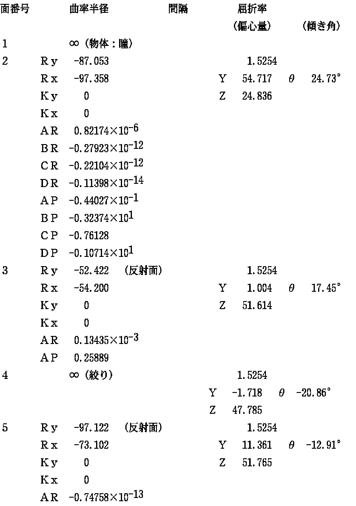
次に、上記実施例1〜13の視線検出光学系の構成パラメータを示すが、後記する構成パラメータは観察者眼球の瞳孔10(物体)から視線検出光学系を経て撮像素子9へ向かう方向のレンズデータとして示してある。
【0063】
そして、座標の取り方は、観察者の瞳孔10中心を原点とし、観察者眼球から撮像素子9に向かう方向(視軸)を正とするZ軸、その観察者視軸に直交し、観察者眼球から見て上下方向の下から上を正とするY軸、観察者視軸に直交し、観察者眼球から見て左右方向の右から左を正とするX軸を定義する。
【0064】
つまり、図3〜図16の紙面内をY−Z面とし、紙面と垂直方向の面をX−Z面とする。そして、下記に示す構成パラメータ中において、偏心Y,Zと傾き角θが記載されている面においては、基準面である瞳孔10の面(1面:物体面)からのその面の面頂のY軸方向、Z軸方向の偏心量及びその面の中心軸のZ軸からの傾き角を意味し、その場合、θが正は反時計回りを意味する。なお、面間隔に意味はない。
【0065】
また、ここでは、簡単のために、接眼光学系2や視線検出光学系の光軸は紙面のY−Z面内て折り曲げられるものとするが、Y−Z面とX−Z面の両方の面内で折り曲げるようにしてもよい。
【0066】
また、下記に示す構成パラメータ中の各面において、非回転対称な非球面形状は、その面を規定する座標上で、Ry 、Rx はそれぞれY−Z面(紙面)内の近軸曲率半径、X−Z面内での近軸曲率半径、Kx 、Ky はそれぞれX−Z面内、X−Z面内の円錐係数、AR、BR、CR、DRはそれぞれZ軸に対して回転対称な4次、6次、8次、10次の非球面係数、AP、BP、CP、DPはそれぞれZ軸に対して回転非対称な4次、6次、8次、10次の非球面係数とすると、非球面式は以下に示す通りである。
【0067】
【0068】
また、後記する構成パラメータ中において値の記載されていないパラメータの値はゼロである。面と面の間の媒質の屈折率はd線(波長587.56nm)の屈折率で表す。なお、長さの単位はmmである。
【0069】
以下に、実施例1〜13の視線検出光学系の構成パラメータを示す。また、実施例1〜13に共通に用いられている接眼光学系2の構成パラメータも示す。但し、各実施例とも、視線検出光の波長は940nmで設計している。(なお、接眼光学系2の面番号は、瞳10から画像表示素子1に向かう逆光線追跡の面番号で示してある。)
【0070】
実施例1
実施例2
実施例3
実施例4
実施例5
実施例6
実施例7
実施例8
実施例9
実施例10
実施例11
実施例12
実施例13
図17に上記の共通に用いる接眼光学系2のY−Z断面図を示す。
なお、前記したように、本発明の映像表示装置の接眼光学系、画像表示素子、照明系を含む全ての光学系は、観察者の上下方向に配置してもよいし、左右方向に配置してもよい。
【0084】
ところで、以上の実施例においては、視線検出用光学部材6あるいは視線検出用光学部材の作用を兼ねたシースルー用補正プリズム30を接着して視線検出光学系を組み込む接眼光学系2として、図1等の示したような3つの面3、4、5からなる断面が三角形の変形プリズムを前提にしていたが、本発明の対象とする接眼光学系2はこれに限らず、反射作用を持つ面を少なくとも1面有する接眼光学系全てが含まれる。その例を図18に示す。図18(a)の場合は、接眼光学系2を4つの面3、4、5、4' で囲まれた変形プリズムで構成し、画像表示素子1からの表示光は第1面3から接眼光学系2内に入射し、反射面4' で反射し、第3面5で全反射し、その後第2面4で反射し、今度は第3面5を通って接眼光学系2から出て観察者瞳10に入射し、中間像を形成することなく画像表示素子11の拡大像を観察可能にするものである。また、図18(b)の場合は、図1等の接眼光学系2の第1面3と第3面5を同じ1面で構成し、しかも第2面4で2回反射させるようにしたものである。この場合は、接眼光学系2を2つの面で囲まれた変形プリズムで構成し、画像表示素子1からの表示光は第1面3から接眼光学系2内に入射し、第2面4でまず1回目の反射をし、第3面5で全反射し、第2面4で2回目の反射し、今度は第3面5を通って接眼光学系2から出て観察者瞳10に入射し、中間像を形成することなく画像表示素子11の拡大像を観察可能にするものである。
【0085】
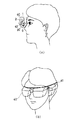
以上、本発明の映像表示装置を実施例に基づいて説明してきたが、本発明はこれらの実施例に限定されず種々の変形が可能である。また、本発明の映像表示装置を頭部装着式映像表示装置(HMD)40として構成するには、図19(a)に断面図、同図(b)に斜視図を示すように、例えばヘッドバンド41を取り付けて、観察者の頭部に装着して使用する。この使用例の場合に、図2に示した形態の接眼光学系を使用し、この接眼光学系の前方に液晶シャッター42を配備し、外界像を選択的に又は画像表示素子1の映像と重畳して観察できるようにしている。
【0086】
【発明の効果】
以上の説明から明らかなように、本発明によれば、映像表示装置の接眼光学系の構成を複雑で設計し難くする等、接眼光学系に負担をかけることなく視線検出光学系を一体に構成することができる。
【図面の簡単な説明】
【図1】本発明に基づく映像表示装置の光学系を模式的に示した図である。
【図2】本発明に基づく映像表示装置の別の光学系を模式的に示した図である。
【図3】本発明の映像表示装置の実施例1の光学系の断面図である。
【図4】本発明の映像表示装置の実施例2の光学系の断面図である。
【図5】本発明の映像表示装置の実施例3の光学系の断面図である。
【図6】本発明の映像表示装置の実施例4の光学系の断面図である。
【図7】本発明の映像表示装置の実施例5の光学系の断面図である。
【図8】本発明の映像表示装置の実施例5の変形例の光学系の断面図である。
【図9】本発明の映像表示装置の実施例6の光学系の断面図である。
【図10】本発明の映像表示装置の実施例7の光学系の断面図である。
【図11】本発明の映像表示装置の実施例8の光学系の断面図である。
【図12】本発明の映像表示装置の実施例9の光学系の断面図である。
【図13】本発明の映像表示装置の実施例10の光学系の断面図である。
【図14】本発明の映像表示装置の実施例11の光学系の断面図である。
【図15】本発明の映像表示装置の実施例12の光学系の断面図である。
【図16】本発明の映像表示装置の実施例13の光学系の断面図である。
【図17】各実施例で共通に用いる接眼光学系の断面図である。
【図18】本発明が適用できる他の接眼光学系の例を示す断面図である。
【図19】本発明の映像表示装置を頭部装着式映像表示装置として構成した場合の例を示す断面図と斜視図である。
【図20】従来の映像表示装置の光学系の1例の断面図である。
【図21】従来の映像表示装置の光学系の別の例の断面図である。
【図22】従来の映像表示装置の光学系のもう1つの例の断面図である。
【図23】従来の映像表示装置の光学系のさらにもう1つの例の断面図である。
【符号の説明】
E 観察者眼球
1 画像表示素子
2 接眼光学系(変形プリズム)
3 第1面
4 第2面
5 第3面
4' 第4面
6 視線検出用光学部材
7、7' 反射面
8 結像光学系
9 撮像素子
10 瞳孔
30 シースルー用補正プリズム
31 シースルー用光学部材の観察者眼球とは反対側の面
32 視線検出用光学部材の反射光の出射面
33 正レンズ
34 反射プリズム
35 視線検出光結像用の面
36 ミラー
37 シースルー用光学部材の下側の面に設けれた反射面
38 ダイクロイックミラー
40 頭部装着式映像表示装置
41 ヘッドバンド
42 液晶シャッター[0001]
BACKGROUND OF THE INVENTION
The present invention relates to a video display device, and more particularly, to a head or face-mounted video display device that can be held on the head or face of an observer.
[0002]
[Prior art]
Conventionally, as an eyepiece optical system of a head or face-mounted image display device (hereinafter referred to as HMD), it is composed of three optical surfaces, and the first surface among them is a refraction to which display light from an image display element is incident. The second surface is a reflecting surface that reflects the light reflected by the remaining third surface and enters the third surface, and the third surface transmits the incident light after passing through the first surface. A surface that also serves as a reflecting surface that reflects the light reflected by the second surface and a refracting surface that refracts the light reflected by the second surface and guides it to the eyes of the observer, and the three surfaces form a triangular deformed prism. The use of these is proposed in JP-A-3-101709, JP-A-8-50256, JP-A-8-179223, JP-A-8-234136, and the like. Each of these has a gaze detection function for detecting the gaze of the observer.
[0003]
FIG. 20 is a cross-sectional view of an optical system according to Japanese Patent Laid-Open No. 3-101709. Display light emitted from the
[0004]
FIG. 21 is a cross-sectional view of an optical system according to Japanese Patent Laid-Open No. 8-50256. Display light emitted from the
[0005]
FIG. 22 is a cross-sectional view (a) and a front view (b) of an optical system according to Japanese Patent Application Laid-Open No. 8-179223. Display light emitted from the
[0006]
FIG. 23 is a cross-sectional view (a) and a front view (b) of the optical system according to Japanese Patent Laid-Open No. 8-234136. The display light emitted from the
[0007]
[Problems to be solved by the invention]
In the above-mentioned Japanese Patent Laid-Open No. 3-101709, the gaze detection optical system and the eyepiece optical system share most, but the eyepiece optical system as a whole is a relay type optical system, and the optical system is enlarged. Yes. Further, when an image of an eye illuminated with infrared rays is formed on the sensor, only the fourth surface 20 has optical power, so that the amount of protrusion of the
[0008]
In the case of Example 1 (FIG. 21) of JP-A-8-50256, it is preferable that the working distance between the image display element and the eyepiece optical system is narrow in terms of aberration correction. In addition, it is preferable in terms of aberration correction that the image display element is inclined with respect to the image display element side incident surface (first surface) of the eyepiece optical system. However, in order to arrange the
[0009]
In Example 2 of JP-A-8-50256, a dichroic mirror is arranged between the third surface of the eyepiece optical system of the deformable prism and the observer's eyeball, and the line of sight is detected by the reflected light. If an attempt is made to secure a certain line-of-sight detection range, the effective diameter of the dichroic mirror increases, and as a result, the amount of protrusion of the line-of-sight detection optical system to the face increases, and it is necessary to change to an eyepiece optical system with large eye relief. There is a problem that occurs.
[0010]
In Example 3 of JP-A-8-50256, the joined body of the deforming
[0011]
In Example 4 of JP-A-8-50256, a dichroic mirror is arranged outside the second surface of the eyepiece optical system of the deformable prism, and the line of sight is detected by the reflected light. The amount of forward protrusion is greatly increased.
[0012]
In Examples 1 to 4 of JP-A-8-50256, in addition to the correction prism for enabling see-through, it is necessary to add an optical member and a lens for enabling visual line detection. There is also a problem that the number of optical members to be processed is large.
[0013]
In JP-A-8-179223, the inclination angle θ of the
[0014]
The inclination angle θ of the
[0015]
That is, in order to satisfy the total reflection condition, it is preferable that the
[0016]
This is preferable because the amount of protrusion of the eyepiece
By the way, it is preferable to set the visual axis OO downward so that an image can be easily observed, and it is preferable to set the visual axis OO downward about 0 to −20 ° from the horizontal direction. In particular, about −10 ° is most preferable.
[0017]
Therefore, when the HMD is mounted, the
[0018]
Furthermore, in consideration of reducing the amount of protrusion to the face side, it is preferable to limit the inclination angle of the
[0019]
Therefore, the condition that the
Furthermore, Japanese Patent Laid-Open No. 8-179223 only discloses that after being reflected by the
[0020]
In Japanese Patent Laid-Open No. 8-234136, the line-of-sight detection optical system is obstructed, and even if a see-through optical member is added, a see-through function cannot be provided.
[0021]
The present invention has been made in view of the above-described problems of the prior art, and an object of the present invention is to provide a head-mounted image display device in which a line-of-sight detection optical system is integrally formed without placing a burden on the eyepiece optical system. It is to provide a video display device particularly suitable for the above.
[0022]
[Means for Solving the Problems]
An image display device according to the present invention that achieves the above object includes an image display element that displays an image, and an eyepiece optical system that has at least one surface having a reflective action for guiding the image displayed on the image display element to an observer's eyeball. And a video display device comprising a line-of-sight detection optical system that forms an image of reflected light of the observer's eyeball on the image sensor,
The line-of-sight detection optical system is bonded to at least the eye-piece optical system having a reflection effect on the line-of-sight detection light emitted from the eyepiece optical system and the observer's eyeball.It is an optical member for see-throughIt is composed of an optical member for line-of-sight detection,
The line-of-sight detection light is transmitted through a surface having a reflective action of the eyepiece optical system, and then the eyepiece optical system.After reflecting on the surface opposite to the observer's eyeball of the see-through optical member through a part and a part of the see-through optical member,
For see-throughAn image of the observer's eyeball is formed on the image sensor without forming an intermediate image by the optical member.
[0023]
This video display device is an embodiment described later.5, 6, 8-13Corresponds.Examples 1 to 4 and 7 are reference examples of the present invention.If comprised in this way, it is not necessary to change the eyepiece optical system which forms image display light, and a visual axis detection function can be added to it.
[0024]
FIG. 1 schematically shows an optical system of an image display apparatus according to the present invention.
First, the coordinate system used in the present invention will be described. The center of the
[0025]
The image display device according to the present invention is typically composed of three
[0026]
In addition to the above, the surface arrangement includes two or more surfaces, but basically includes one or more reflective surfaces (
[0027]
Further, based on the present invention, a visual line detecting
[0028]
The light reflected by the reflection action of the visual line detection
With such a configuration, the amount of protrusion of the line-of-sight detection optical system can be reduced by the deflection action caused by the reflection of the line-of-sight detection
[0029]
In the above case, it is desirable that the optical member for line-of-sight detection has a reflecting action and optical power.
Examples 1 to 13 described later correspond to this video display device.
[0030]
With this configuration, as shown in FIG. 1, if all the functions of the imaging
[0031]
Further, it is desirable that the line-of-sight detection light is deflected in a direction substantially opposite to the image display element direction by a reflection action by the line-of-sight detection optical member.
Examples 1 to 13 described later correspond to this video display device.
[0032]
With this configuration, as shown in FIG. 1, when the eyepiece
[0033]
Further, it is desirable that the reflective surface of the visual axis detection optical member is made of a dichroic film that transmits visible light and reflects infrared light.
Examples 1 to 13 described later correspond to this video display device.
[0034]
With this configuration, it is possible to perform line-of-sight detection using infrared light without causing a decrease in the amount of video or external light displayed on the image display element.
Further, the visual axis detection optical member is an optical member for see-through, and the visual axis detection optical system is an observer of the optical member for see-through through a part of the eyepiece optical system for image observation and a part of the optical member for see-through. An image can be formed on the image sensor after being reflected by the surface opposite to the eyeball.
[0035]
This video display apparatus corresponds to Examples 5, 6, and 8 to 13 described later.
As shown in FIG. 2, when the eyepiece optical system including the
[0036]
For example, the visible light transmittance of the
[0037]
As described in the section of the problem to be solved by the invention, the
[0038]
By reflecting on the
[0039]
In this way, the line-of-sight detection optical system can be configured without affecting the optical system for observing the image of the
[0040]
In the case of FIG. 1, a line-of-sight detection function is added by the line-of-sight detection
[0041]
When the above-described optical member for line-of-sight detection is an optical member for see-through, the optical path of the line-of-sight detection light passes through a part of the eyepiece optical system from the observer's eyeball, and passes through a part of the optical member for see-through. It can reflect on the surface of the optical member for use opposite to the observer's eyeball, reflect on the joint surface between the eyepiece optical system and the see-through optical member, and reach the image sensor from the imaging optical system.
[0042]
This video display apparatus corresponds to Examples 5, 6, and 8 to 12 described later.
As described above, since the optical path of the line-of-sight detection light is reflected twice, the line-of-sight detection optical system can be arranged on the side opposite to the face side. Therefore, the line-of-sight detection optical system is configured without increasing the burden on the eye-piece optical system, such as the necessity of securing eye relief of the eyepiece optical system more than necessary because the line-of-sight detection optical system protrudes to the face side. be able to. Further, by performing the reflection twice, an effect of folding the optical path is obtained, and the protrusion amount of the line-of-sight detection optical system is reduced.
[0043]
Further, the optical path of the line-of-sight detection light passes through a part of the eyepiece optical system from the observer eyeball, passes through a part of the see-through optical member, and is reflected by the surface opposite to the observer eyeball of the see-through optical member. And reflected from the joint surface between the eyepiece optical system and the see-through optical member, reflected from the surface of the see-through optical member opposite to the observer's eyeball, and reach the image sensor from the imaging optical system. it can.
[0044]
This video display apparatus corresponds to Examples 8 and 10 to 12 described later.
As described above, the optical path of the visual line detection light is reflected three times, so that the effect of folding the optical path is increased, and the protrusion amount of the visual line detection optical system is reduced.
[0045]
Further, the line-of-sight detection optical system may be configured by a see-through optical member and a prism bonded thereto.
This video display apparatus corresponds to Examples 9 and 11 described later.
[0046]
If each surface of the line-of-sight detection optical system is composed of independent optical elements such as a reflecting surface and a lens, it is necessary to strictly set the angle and distance when arranging each optical element. However, if the line-of-sight detection optical system is integrally formed as a single prism and is joined to an optical member composed of an eyepiece optical system and a see-through optical member, assembly is facilitated and productivity is improved.
[0047]
In the video display device of the present invention, it is desirable that at least one of the surfaces constituting the line-of-sight detection optical system has different optical functions in the X direction and the Y direction.
[0048]
Examples 1 to 13 described later correspond to this video display device.
In FIG. 1, a
[0049]
DETAILED DESCRIPTION OF THE INVENTION
Embodiments of the video display device according to the present invention will be described below.5, 6, 8-13about7 to 9 and FIGS. 11 to 16Will be described with reference to FIG.Examples 1 to 4 and 7 are reference examples of the present invention.
[0050]
Here, for the sake of simplicity, the optical axes of the eyepiece
[0051]
Further, as described in the section of the problem to be solved by the invention, it is preferable that the visual axis is set downward from the horizontal direction. However, in each of the following embodiments, the visual axis is directed to the horizontal direction. Designed.
[Example 1]
FIG. 3 is a YZ cross section of the optical system of the first embodiment of the image display device according to the present invention. The
[0052]
In order to detect the line of sight of the observer's eyeball, an infrared light source (not shown) that irradiates the observer's eyeball with infrared light is disposed obliquely in front of the observer's eyeball (see FIGS. 21 to 23). A line-of-sight detection is performed by taking an image of the cornea reflection image of the observer's eyeball obtained by illumination or an image of the
[0053]
In the first embodiment, as shown in FIG. 3, a gaze detection optical system in which a
[0054]
Here, the reflecting
[Example 2]
4 is a YZ cross section of the optical system of Example 2 of the image display device according to the present invention. A
Example 3
FIG. 5 is a YZ cross section of the optical system of the third embodiment of the image display device according to the present invention, and uses a reflecting
Example 4
FIG. 6 is a YZ cross section of the optical system of Example 4 of the video display device according to the present invention. In this example, the line of sight detection is performed on the
[0055]
Furthermore, when it is desired to add a see-through function, a see-through
Example 5
FIG. 7 is a YZ cross section of the optical system of Example 5 of the image display device according to the present invention. In this example, external light is applied to the
[0056]
Here, the
[0057]
As a modification of FIG. 7, as shown in FIG. 8, a
Example 6
FIG. 9 is a YZ cross section of the optical system of Example 6 of the image display device according to the present invention. A positive lens (eccentric positive lens) 33 is added to the configuration of Example 5, and the
Example 7
FIG. 10 is a YZ cross section of the optical system of Example 7 of the image display device according to the present invention. In this example, the line of sight detection is performed on the
[0058]
Furthermore, when it is desired to add a see-through function, a see-through
Example 8
FIG. 11 is a YZ cross section of the optical system of Example 8 of the image display device according to the present invention.
In this embodiment, a see-through
[0059]
Also in this case, since the
In this example, the diaphragm position is substantially coincident with the second reflection position on the
Example 9
FIG. 12 is a YZ cross section of the optical system of Example 9 of the image display device according to the present invention. In this example, external light is applied to the
Example 10
FIG. 13 is a YZ cross section of the optical system of Example 10 of the image display device according to the present invention, and uses a reflecting
Example 11
FIG. 14 is a YZ cross section of the optical system of Example 11 of the image display device according to the present invention. In this example, external light is applied to the
Example 12
FIG. 15 is a YZ cross section of the optical system of Example 12 of the image display device according to the present invention, in which the reflecting
[0060]
Example 13
FIG. 15 is a YZ cross section of the optical system of Example 12 of the image display device according to the present invention, in which the reflecting
[0061]
FIG. 16 is a YZ cross section of the optical system of Example 13 of the image display device according to the present invention. In this example, the
[0062]
Next, the configuration parameters of the line-of-sight detection optical systems of Examples 1 to 13 will be described. The configuration parameters described later are lenses in the direction from the pupil 10 (object) of the observer's eyeball to the
[0063]
The coordinates are set in such a manner that the center of the
[0064]
That is, the inside of the paper surface of FIGS. 3 to 16 is the YZ plane, and the surface perpendicular to the paper surface is the XZ plane. In the configuration parameters shown below, on the surface where the eccentricity Y, Z and the inclination angle θ are described, the surface apex of the surface from the surface (one surface: object surface) of the
[0065]
Here, for the sake of simplicity, the optical axes of the eyepiece
[0066]
In addition, the configuration parameters shown belowInIn each plane, the non-rotationally symmetric aspherical shape is a coordinate that defines the plane, and Ry and Rx are paraxial radii of curvature in the YZ plane (paper plane) and paraxial in the XZ plane, respectively. The radius of curvature, Kx and Ky are in the XZ plane, the cone coefficient in the XZ plane, and AR, BR, CR and DR are the 4th, 6th, 8th, 10th, respectively, rotationally symmetric about the Z axis. The following aspheric coefficients, AP, BP, CP, and DP, are assumed to be rotationally asymmetric fourth-order, sixth-order, eighth-order, and tenth-order aspheric coefficients, respectively. is there.
[0067]
[0068]
In addition, among the configuration parameters described later, the value of a parameter whose value is not described is zero. The refractive index of the medium between the surfaces is represented by the refractive index of the d line (wavelength 587.56 nm). The unit of length is mm.
[0069]
The configuration parameters of the line-of-sight detection optical systems of Examples 1 to 13 are shown below. In addition, configuration parameters of the eyepiece
[0070]
Example 1
Example 2
Example 3
Example 4
Example 5
Example 6
Example 7
Example 8
Example 9
Example 10
Example 11
Example 12
Example 13
FIG. 17 shows a YZ sectional view of the eyepiece
As described above, all the optical systems including the eyepiece optical system, the image display element, and the illumination system of the video display device of the present invention may be arranged in the vertical direction of the observer or in the horizontal direction. May be.
[0084]
By the way, in the above embodiment, the eyepiece
[0085]
As described above, the video display device of the present invention has been described based on the embodiments. However, the present invention is not limited to these embodiments, and various modifications are possible. Further, in order to configure the video display device of the present invention as a head-mounted video display device (HMD) 40, as shown in a sectional view in FIG. 19A and a perspective view in FIG. A
[0086]
【The invention's effect】
As is apparent from the above description, according to the present invention, the line-of-sight detection optical system is integrally configured without imposing a burden on the eyepiece optical system, such as making the configuration of the eyepiece optical system of the video display device complicated and difficult to design. can do.
[Brief description of the drawings]
FIG. 1 is a diagram schematically showing an optical system of an image display device according to the present invention.
FIG. 2 is a diagram schematically showing another optical system of the video display device according to the present invention.
FIG. 3 is a cross-sectional view of the optical system according to the first embodiment of the video display apparatus of the present invention.
FIG. 4 is a sectional view of an optical system according to a second embodiment of the video display apparatus of the present invention.
FIG. 5 is a sectional view of an optical system according to a third embodiment of the video display apparatus of the present invention.
FIG. 6 is a sectional view of an optical system according to a fourth embodiment of the video display apparatus of the present invention.
FIG. 7 is a sectional view of an optical system according to a fifth embodiment of the video display device of the present invention.
FIG. 8 is a cross-sectional view of an optical system according to a modification of Example 5 of the video display device of the present invention.
FIG. 9 is a sectional view of an optical system according to a sixth embodiment of the video display apparatus of the present invention.
FIG. 10 is a sectional view of an optical system according to a seventh embodiment of the video display apparatus of the present invention.
FIG. 11 is a sectional view of an optical system according to an eighth embodiment of the video display apparatus of the present invention.
12 is a sectional view of an optical system according to Example 9 of a video display apparatus of the present invention. FIG.
FIG. 13 is a cross-sectional view of an optical system according to Example 10 of a video display device of the present invention.
FIG. 14 is a sectional view of an optical system according to an eleventh embodiment of the video display apparatus of the present invention.
FIG. 15 is a sectional view of an optical system according to a twelfth embodiment of the video display apparatus of the present invention.
FIG. 16 is a sectional view of an optical system according to Example 13 of a video display apparatus of the present invention.
FIG. 17 is a cross-sectional view of an eyepiece optical system commonly used in each embodiment.
FIG. 18 is a cross-sectional view showing an example of another eyepiece optical system to which the present invention can be applied.
FIGS. 19A and 19B are a cross-sectional view and a perspective view illustrating an example in which the video display device of the present invention is configured as a head-mounted video display device.
FIG. 20 is a cross-sectional view of an example of an optical system of a conventional video display device.
FIG. 21 is a cross-sectional view of another example of an optical system of a conventional video display device.
FIG. 22 is a cross-sectional view of another example of an optical system of a conventional video display device.
FIG. 23 is a cross-sectional view of still another example of an optical system of a conventional video display device.
[Explanation of symbols]
E Observer eyeball
1 Image display element
2 Eyepiece optical system (deformation prism)
3 1st page
4 Second side
5 Third side
4 '4th page
6 Optical members for eye-gaze detection
7, 7 'reflective surface
8 Imaging optical system
9 Image sensor
10 Pupil
30 See-through correction prism
31 The surface of the see-through optical member opposite to the observer's eyeball
32 Output surface of reflected light of optical member for detecting line of sight
33 positive lens
34 Reflective prism
35 Gaze detection light imaging surface
36 mirror
37 Reflective surface provided on the lower surface of the see-through optical member
38 Dichroic Mirror
40 Head-mounted video display device
41 headband
42 LCD shutter
Claims (4)
前記視線検出光学系は、少なくとも前記接眼光学系と観察者眼球から出る視線検出光に対して反射作用を持つ前記接眼光学系に接着されたシースルー用光学部材である視線検出用光学部材とから構成され、
前記視線検出光は、前記接眼光学系の反射作用を持つ面を透過後、前記接眼光学系の一部と前記シースルー用光学部材の一部を介して、前記シースルー用光学部材の観察者眼球とは反対側の面で反射した後に、
前記シースルー用光学部材により中間像を形成せずに観察者眼球の像を前記撮像素子上に結像することを特徴とする映像表示装置。An image display element for displaying an image, an eyepiece optical system having at least one surface having a reflection effect for guiding the image displayed on the image display element to the observer's eyeball, and reflected light of the observer's eyeball are coupled to the imaging element. In a video display device composed of a line-of-sight detection optical system for imaging,
The line-of-sight detection optical system includes at least the eye-piece optical system and a line-of-sight detection optical member that is a see-through optical member bonded to the eye-piece optical system having a reflection effect on the line-of-sight detection light emitted from the observer's eyeball. And
The line-of-sight detection light passes through the reflective surface of the eyepiece optical system and then passes through a part of the eyepiece optical system and a part of the see-through optical member to the observer eyeball of the see-through optical member. Is reflected on the opposite side,
An image display apparatus, wherein an image of an observer's eyeball is formed on the image sensor without forming an intermediate image by the see-through optical member.
Priority Applications (1)
| Application Number | Priority Date | Filing Date | Title |
|---|---|---|---|
| JP33410197A JP4040730B2 (en) | 1997-09-26 | 1997-12-04 | Video display device |
Applications Claiming Priority (3)
| Application Number | Priority Date | Filing Date | Title |
|---|---|---|---|
| JP9-261954 | 1997-09-26 | ||
| JP26195497 | 1997-09-26 | ||
| JP33410197A JP4040730B2 (en) | 1997-09-26 | 1997-12-04 | Video display device |
Publications (3)
| Publication Number | Publication Date |
|---|---|
| JPH11161191A JPH11161191A (en) | 1999-06-18 |
| JPH11161191A5 JPH11161191A5 (en) | 2005-07-07 |
| JP4040730B2 true JP4040730B2 (en) | 2008-01-30 |
Family
ID=26545312
Family Applications (1)
| Application Number | Title | Priority Date | Filing Date |
|---|---|---|---|
| JP33410197A Expired - Fee Related JP4040730B2 (en) | 1997-09-26 | 1997-12-04 | Video display device |
Country Status (1)
| Country | Link |
|---|---|
| JP (1) | JP4040730B2 (en) |
Cited By (1)
| Publication number | Priority date | Publication date | Assignee | Title |
|---|---|---|---|---|
| US12535882B2 (en) | 2020-09-03 | 2026-01-27 | Samsung Electronics Co., Ltd. | Electronic device and method for acquiring user's gaze information |
Families Citing this family (2)
| Publication number | Priority date | Publication date | Assignee | Title |
|---|---|---|---|---|
| KR102801280B1 (en) | 2020-06-18 | 2025-04-30 | 삼성전자주식회사 | Augmented reality glass and operating method thereof |
| CN113885247B (en) * | 2020-07-03 | 2024-03-01 | 松下知识产权经营株式会社 | display system |
-
1997
- 1997-12-04 JP JP33410197A patent/JP4040730B2/en not_active Expired - Fee Related
Cited By (1)
| Publication number | Priority date | Publication date | Assignee | Title |
|---|---|---|---|---|
| US12535882B2 (en) | 2020-09-03 | 2026-01-27 | Samsung Electronics Co., Ltd. | Electronic device and method for acquiring user's gaze information |
Also Published As
| Publication number | Publication date |
|---|---|
| JPH11161191A (en) | 1999-06-18 |
Similar Documents
| Publication | Publication Date | Title |
|---|---|---|
| US6317267B1 (en) | Head or face mounted image display apparatus | |
| USRE37175E1 (en) | Image display apparatus | |
| JP3847799B2 (en) | Display device having gaze detection system | |
| USRE37579E1 (en) | Image display apparatus comprising an internally reflecting ocular optical system | |
| US5812323A (en) | Image display apparatus | |
| JP3854763B2 (en) | Image display device | |
| US6008778A (en) | Visual display apparatus | |
| JP3672951B2 (en) | Image display device | |
| US5659430A (en) | Visual display apparatus | |
| US6342871B1 (en) | Image display apparatus | |
| USRE37292E1 (en) | Optical system and optical apparatus | |
| JP4646374B2 (en) | Image observation optical system | |
| US6646811B2 (en) | Optical element and compound display apparatus using the same | |
| US6310736B1 (en) | Image-forming optical system and viewing optical system | |
| US5886824A (en) | Image display apparatus | |
| JPH09166759A (en) | Picture display device | |
| US20010022689A1 (en) | Image display apparatus | |
| JPH10239628A (en) | Composite display | |
| JP2005202060A (en) | Observation optical system | |
| US7391575B2 (en) | Image display apparatus | |
| JP4040730B2 (en) | Video display device | |
| JP3683338B2 (en) | Head-mounted image display device | |
| JP3870076B2 (en) | Image display device and imaging device | |
| JP4804644B2 (en) | Observation optical system, imaging optical system, and apparatus using the same | |
| JP3870073B2 (en) | Image display device and imaging device |
Legal Events
| Date | Code | Title | Description |
|---|---|---|---|
| A521 | Written amendment |
Effective date: 20041102 Free format text: JAPANESE INTERMEDIATE CODE: A523 |
|
| A621 | Written request for application examination |
Free format text: JAPANESE INTERMEDIATE CODE: A621 Effective date: 20041102 |
|
| A977 | Report on retrieval |
Free format text: JAPANESE INTERMEDIATE CODE: A971007 Effective date: 20060403 |
|
| A131 | Notification of reasons for refusal |
Free format text: JAPANESE INTERMEDIATE CODE: A131 Effective date: 20070710 |
|
| A521 | Written amendment |
Free format text: JAPANESE INTERMEDIATE CODE: A523 Effective date: 20070904 |
|
| TRDD | Decision of grant or rejection written | ||
| A01 | Written decision to grant a patent or to grant a registration (utility model) |
Effective date: 20071106 Free format text: JAPANESE INTERMEDIATE CODE: A01 |
|
| A61 | First payment of annual fees (during grant procedure) |
Free format text: JAPANESE INTERMEDIATE CODE: A61 Effective date: 20071108 |
|
| FPAY | Renewal fee payment (prs date is renewal date of database) |
Year of fee payment: 3 Free format text: PAYMENT UNTIL: 20101116 |
|
| FPAY | Renewal fee payment (prs date is renewal date of database) |
Year of fee payment: 3 Free format text: PAYMENT UNTIL: 20101116 |
|
| FPAY | Renewal fee payment (prs date is renewal date of database) |
Free format text: PAYMENT UNTIL: 20101116 Year of fee payment: 3 |
|
| FPAY | Renewal fee payment (prs date is renewal date of database) |
Year of fee payment: 4 Free format text: PAYMENT UNTIL: 20111116 |
|
| FPAY | Renewal fee payment (prs date is renewal date of database) |
Free format text: PAYMENT UNTIL: 20111116 Year of fee payment: 4 |
|
| FPAY | Renewal fee payment (prs date is renewal date of database) |
Year of fee payment: 5 Free format text: PAYMENT UNTIL: 20121116 |
|
| FPAY | Renewal fee payment (prs date is renewal date of database) |
Year of fee payment: 6 Free format text: PAYMENT UNTIL: 20131116 |
|
| LAPS | Cancellation because of no payment of annual fees |