JP4040439B2 - Toner and toner production method - Google Patents
Toner and toner production method Download PDFInfo
- Publication number
- JP4040439B2 JP4040439B2 JP2002352033A JP2002352033A JP4040439B2 JP 4040439 B2 JP4040439 B2 JP 4040439B2 JP 2002352033 A JP2002352033 A JP 2002352033A JP 2002352033 A JP2002352033 A JP 2002352033A JP 4040439 B2 JP4040439 B2 JP 4040439B2
- Authority
- JP
- Japan
- Prior art keywords
- toner
- polymerization
- image
- toner according
- polymerized toner
- Prior art date
- Legal status (The legal status is an assumption and is not a legal conclusion. Google has not performed a legal analysis and makes no representation as to the accuracy of the status listed.)
- Expired - Fee Related
Links
Images


Description
【0001】
【発明の属する技術分野】
本発明は、電子写真法、静電記録法、トナージェット方式記録法などを利用した、静電荷潜像を顕像化するためのトナー及びトナーの製造方法に関する。
【0002】
【従来の技術】
従来、電子写真法としては多数の方法が知られているが、一般には光導電性物質を利用し、種々の手段により静電荷像担持体(以下、感光体ともいう)上に電気的潜像を形成し、次いで該潜像をトナーで現像を行なって可視像とし、必要に応じて紙などの転写材にトナー像を転写した後、熱・圧力等により転写材上にトナー画像を定着して複写物を得るものである。
【0003】
また、プリンター装置はLED、LBPプリンターが最近の市場の主流になっており、技術の方向としてより高解像度即ち、従来240、300dpiであったものが400、600、800dpiとなって来ている。従って現像方式もこれにともなって、より高精細が要求されてきている。また、複写機においても高機能化が進んでおり、そのためデジタル化の方向に進みつつある。この方向は、静電潜像をレーザーで形成する方法が主であるため、やはり高解像度の方向に進んでおり、ここでもプリンターと同様に高解像・高精細の現像方式が要求されてきている。この要求を満たす一つの手段としてトナーの小粒径化が進んでおり、特許文献1〜6などでは特定の粒度分布で粒径の小さいトナーが提案されている。
【0004】
このように近年、高解像度・高精細のためトナーの粒径を小さくする方向に進んでいるが、このようにトナー粒径が小さくなるほど、トナー粉体の安定な摩擦帯電は重要な技術となる。即ち、細かい個々のトナー粒子に均一な帯電量を持たせないと、前述したような画像安定性の低下がより顕著に現れやすい。これは、単純にトナーの粒径が小さくなるだけで、転写工程でトナー粒子にかかるクーロン力に比して、トナー粒子の感光体への付着力(鏡像力やファンデルワールス力など)が大きくなり、結果として転写残トナーが増加することに加えて、トナーの小径化には流動性の悪化が伴うため個々のトナー粒子の帯電量が不均一となりやすく、カブリや転写性の悪いトナー粒子が多くなるためである。
【0005】
このような背景により、トナーの性能向上のためには、より安定な帯電特性の維持が必要不可欠である。トナーの帯電を決定する因子は、トナー粒子同士が摩擦することによって発生する電荷量、及びトナー粒子が外部部材と摩擦もしくは接触することによって発生する電荷量等に大別されるが、各トナー粒子の表面材料及びトナー粒子の大きさと形状、帯電補助を目的とした外部添加剤、金属またはゴム材などを用いた規制部材、トナー粒子の構成材料である荷電制御剤の影響が大きく関与している。
【0006】
例えば、ネガ系荷電制御剤としてサリチル酸、アルキルサリチル酸、ジアルキルサリチル酸、ナフトエ酸、ダイカルボン酸の如き芳香族カルボン酸の金属化合物、アゾ染料もしくはアゾ顔料の金属塩または金属錯体、スルホン酸又はカルボン酸基を側鎖に持つ高分子型化合物、ホウ素化合物、尿素化合物、ケイ素化合物、カリックスアレーンまた、ポジ系荷電制御剤として四級アンモニウム塩、その四級アンモニウム塩を側鎖に有する高分子型化合物、グアニジン化合物、ニグロシン系化合物、イミダゾール化合物のような様々な荷電制御剤及びその存在状態が特許文献7〜10等に開示されている。しかし、これらの公報に開示されている技術も、荷電制御剤はトナー粒子中をランダムに点在するため、帯電均一性について依然として不十分であった。
【0007】
一方、近年、他成分との相溶性に優れ、均一に帯電できる点から、極性高分子の荷電制御剤が注目されており、特許文献11〜17において、スルホン酸基、或いは類似の官能基を必須成分として含有する単量体を用いたトナーとして開示されている。しかしながら、これらの荷電制御剤も帯電においてはある程度十分な性能を有するものの、制御剤そのものがトナー中の着色剤の分散性やトナー流動性にも影響を与えるため、帯電をするのに十分な量を添加した場合、過度のすべりが生じ、帯電分布の広いトナーとなることがわかってきており、またこれら極成高分子の荷電制御剤と無機系金属錯体の荷電制御剤とで併用した場合には、各荷電制御剤がその化学構造に起因した各々の帯電性能を発現するため特に帯電分布の広いトナーとなる。
【0008】
更に、上記問題点を改善し良好なトナーの流動特性、帯電特性等を得るためにトナー母粒子に外部添加剤として無機微粒子を添加する方法も提案され、広く用いられている。
【0009】
例えば、特許文献18及び19等で疎水化処理を施した無機微粒子若しくは疎水化処理した後さらにシリコーンオイル等で処理した無機微粒子を添加、特許文献20及び21で疎水化処理無機微粒子とシリコーンオイル処理無機微粒子を併用添加する方法が知られている。
【0010】
しかしながら、こういった改良手段を用いても、流動性・帯電性の双方の特性に関して性能を十分に引き出すには不十分であり、結果として画像特性及び耐久性にも十分な改良効果があるとは言い難い。
【0011】
一方、トナーの定着性の改良については、これまでに様々な提案がされている。例えば、特許文献22〜24等にワックスをトナー粒子に含有させることが開示されている。
【0012】
ワックスは、トナーの低温定着時や高温定着時の耐オフセット性の向上や、低温定着時の定着性の向上のために用いられている。反面、トナーの耐ブロッキング性を低下させたり、機内の昇温によってトナーの現像性が低下したり、また高温高湿下に長期間トナーを放置した際にワックスがトナー粒子表面にマイグレーションして現像性が低下したりする。
【0013】
上記の課題に対して懸濁重合法により生成したトナーが提案されている。例えば、特許文献25によれば、水系分散媒体中において、単量体組成物中に極性成分を添加すると、単量体組成物に含まれる極性基を有する成分は水相との界面である表層部に存在し易くなり、非極性の成分は表層部に存在しにくくなり、そのため、トナー粒子はコア/シェル構造をとることが可能となる。
【0014】
その結果、生成されたトナーは、トナー粒子内へのワックスの内包化により、耐ブロッキング性と耐高温オフセット性という相反する性能を両立することが可能となり、かつ定着ローラーにオイルの如き離型剤を塗布することなく、高温オフセットを防止することが可能となる。
【0015】
しかしながら、低温定着性については、コア/シェル構造を有するトナーのコア部のワックスをいかに迅速に定着時にトナー表層へ染み出させるかが重要な課題である。
【0016】
また、特許文献26では、重合トナーの製造方法において、油溶性重合開始剤の存在下に懸濁重合を行い、次いで、レドックス開始剤用還元剤を添加することで、低温定着性と耐ブロッキング性を両立することを提案している。しかし、該効果についてはある程度満足しているものの、該公報ではレドックス開始剤用還元剤の添加時期が重合転化率30〜97%と早期に添加するため、また該レドックス開始剤用還元剤添加時と同時に重合性単量体を添加するため、局所的に生じる超低分子量が原因となり帯電の均一性が損なわれるだけでなく、該超低分子量成分がトナー粒子の表層近傍に存在することにより特に高温高湿環境下においてトナー融着が発生することが分かってきた。
【0017】
また、特許文献27では、ワックスエマルションをレドックス開始剤を用いてシード重合して得た、重合体一次粒子を凝集して製造するトナーについての技術が開示されており、該重合体一次粒子がワックスを実質的に包含することにより定着領域が拡大することを提案している。しかし、開始剤と同時にレドックス開始剤用還元剤を添加することが原因で、開始剤の分解が局所的に生じるため、超低分子量成分を発生させ、トナー融着を引き起こすことが分かってきた。
【0018】
以上のように、現像性と転写性に加えて、低温定着性やトナー融着抑制をも十分に満足できるトナーが求められている。
【0019】
【特許文献1】
特開平1−112253号公報
【特許文献2】
特開平1−191156号公報
【特許文献3】
特開平2−214156号公報
【特許文献4】
特開平2−284158号公報
【特許文献5】
特開平3−181952号公報
【特許文献6】
特開平4−162048号公報
【特許文献7】
特開平4−303850号公報
【特許文献8】
特開平6−138707号公報
【特許文献9】
特開平6−348055号公報
【特許文献10】
特開平7−20657号公報
【特許文献11】
特開平3−15858号公報
【特許文献12】
特開平3−56974号公報
【特許文献13】
特開平8−179564号公報
【特許文献14】
特開平11−184165号公報
【特許文献15】
特開平11−28126号公報
【特許文献16】
特開平11−327208号公報
【特許文献17】
特開2000−56518号公報
【特許文献18】
特開平5−66608号公報
【特許文献19】
特開平4−9860号公報
【特許文献20】
特開平4−264453号公報
【特許文献21】
特開平5−346682号公報
【特許文献22】
特開平3−50559号公報
【特許文献23】
特開平2−79860号公報
【特許文献24】
特開平1−109359号公報
【特許文献25】
特開平5−341573号公報
【特許文献26】
特開平11−202553号公報
【特許文献27】
特開2001−27821号公報
【0020】
【発明が解決しようとする課題】
本発明の目的は、上記従来技術の問題点を解決したトナーの製造方法及び、該方法で製造した重合トナーを提供することにある。
【0021】
即ち本発明の目的は、帯電安定性に優れ、良好な低温定着性を有し、高温高湿環境下においてもトナー融着が生じず、高精細な画像が得られるトナーの製造方法及び、該方法で製造した重合トナーを提供することにある。
【0022】
【課題を解決するための手段】
本発明は、少なくとも着色剤を含有する重合性単量体組成物を重合する重合トナーの製造方法において、該重合性単量体組成物の重合転化率が98〜99.7%でレドックス開始剤用還元剤を添加することを特徴とする重合トナーの製造方法及び、該方法で製造した重合トナーに関する。
【0023】
【発明の実施形態】
本発明者らが鋭意検討を行なったところ、少なくとも着色剤を含有する重合性単量体組成物を重合する重合トナーの製造方法において、該重合性単量体組成物の重合転化率が98%以上でレドックス開始剤用還元剤を添加することが、重合トナーの帯電安定性及び、トナー融着抑制のために有効であることが判明した。
【0024】
高精細な画像を得る為には小粒径トナーが有利である。しかし、小粒径のトナーの帯電量を適度に制御して、カブリやゴースト、現像性を良好なものとするためには、本発明に示すようにレドックス開始剤用還元剤添加時のトナー粒子の重合転化率が非常に重要なものとなる。
【0025】
具体的には、該重合性単量体組成物の重合転化率が98%以上で、該レドックス開始剤用還元剤を添加することが必須となる。
【0026】
該重合転化率以上のときにレドックス開始剤用還元剤を添加するのが必須である理由として、詳細には解明されていないが、極性の高いレドックス開始剤用還元剤が酸化剤(開始剤)との反応時にトナー粒子中に取り込まれ、トナー粒子表層近傍に存在することにより、トナー粒子の摩擦帯電時における帯電移動速度が向上し、高湿環境下においても帯電量の低下が抑制できると考えている。
【0027】
重合転化率が98%未満では、トナー粒子中に単量体が多量に存在していることから、該重合転化率の範囲でレドックス開始剤用還元剤を添加することにより、トナー粒子の粘弾性が低く、その為、添加したレドックス開始剤用還元剤がトナー内部に移動しやすくなり、トナー内部に埋め込まれることになる。更に、超低分子量成分の存在も増大傾向を示し、その結果、トナーの帯電性が不均一となり易い。更には、高温高湿環境下においてはトナー融着も生じやすくなると考えている。
【0028】
また、10000≦Mw≦1500000の範囲の時、レドックス開始剤用還元剤を添加することが好ましい。
【0029】
Mw<10000では、トナー粒子の粘性が低い傾向にありレドックス開始剤用還元剤をトナー表層近傍に存在させることが困難になる。更に該分子量範囲でのレドックス開始剤用還元剤の添加は、トナー粒子の局所的に超低分子量成分を存在させやすくなり、トナー粒子の帯電性が不均一になりやすいばかりではなく、特に高温高湿環境下において連続印字することによりトナー融着が生じやすいと考えている。また、Mw>1500000では、粒子表面の剛性が増しやすくなることにより、トナー粒子中にレドックス還元剤が取り込まれづらくなるためトナー粒子の帯電性は不均一となりやすく、また低温定着性も損なわれやすいと考えている。
【0030】
更に、本発明のトナーは重合開始剤として10時間半減期温度が50℃を超える有機過酸化物を開始剤として用いて重合性単量体組成物を重合することが好ましい。50℃以下の有機過酸化物を開始剤として使用した場合、開始剤の分解速度が著しいことにより反応を制御しにくく、トナー粒子の局所的に超低分子量成分が存在する傾向が強く、帯電均一性の悪化や、特に高温高湿環境下においてドラム融着の発生の原因となる場合がある。
【0031】
更に該有機過酸化物開始剤がt−ブチルパーオキシピバレ−ト(10時間半減期温度54.6℃)、t−ブチルパーオキシ−2−エチルヘキサノエート(10時間半減期温度72.1℃)、t−ブチルパーオキシイソブチレート(10時間半減期温度77.3℃)から選ばれることが好ましい。
【0032】
これは、これら有機過酸化物が分解し、その一部が水素引き抜き反応によってt−ブタノールを生じることで、トナーバインダー樹脂中により均一に分散されるためと考えられる。本発明者らが鋭意検討を行なったところ、トナー中にt−ブタノールを極微量含有させることが、トナー内部に存在しているワックスを定着時に瞬時にトナー表層へ染み出させるために有効であることが判明した。t−ブタノールが有効である理由として、融点が常温に近い約26℃であるため、定着時に瞬時に溶解することで可塑剤として働き、ワックスがトナー表層へ染み出しやすくなるためと考えられる。
【0033】
本発明において、トナー中にt−ブタノールの含有量としては、0.1から1000ppmが好ましい。0.1ppm未満では上記効果が不十分となり、逆に1000ppmを超えてしまうと、高温高湿下等でトナーの耐ブロッキング性や流動性が悪化したり、帯電部材や感光体へのトナー融着が発生しやすくなる。
【0034】
本発明のトナー中のt−ブタノールの含有量は、ガスクロマトグラフィーにより、検量線を作成し、内部標準法により容易に測定される。
【0035】
また、本発明に使用される還元剤としては、Fe2+塩や亜硫酸塩、アルコール、アミン(ポリアミン、第三アミン)、ナフテン酸塩、メルカプタンなどが挙げられるが、この中で硫黄または窒素元素を含有しない有機化合物であることが好ましく、更には、アスコルビン酸の塩であることがより好ましい。これは、硫黄や、窒素原子を有する有機化合物がトナー中に残存した場合、トナーの帯電性が劣化する傾向にある。特にネガ性トナーの場合、窒素原子を含有する有機化合物が残存すると帯電性に好ましくない。還元剤としてアスコルビン酸の塩を使用した場合、水系媒体中での重合反応時に分散安定剤の効果も得られ、得られるトナー粒子の粒度分布は非常にシャープなものとなるため好ましい。
【0036】
本発明のトナーは定着性向上のために、ワックスを含有することが好ましい。結着樹脂に対し1〜30質量%を含有することが好ましい。より好ましくは、3〜25質量%である。ワックスの含有量が1質量%未満ではワックスの添加効果が十分ではなく、さらに、オフセット抑制効果も不十分である。一方、30質量%を超えてしまうと長期間の保存性が悪化すると共に、着色剤等のトナー材料の分散性が悪くなり、トナーの着色力の悪化や画像特性の低下につながる。また、ワックスのしみ出しも起こりやすくなり、高温高湿下での耐久性が劣るものとなる。さらに、多量のワックスを内包するために、トナー形状がいびつになりやすくなる。
【0037】
本発明のトナーに使用可能な離型剤としては、パラフィンワックス、マイクロクリスタリンワックス、ペトロラクタム等の石油系ワックス及びその誘導体、モンタンワックス及びその誘導体、フィッシャートロプシュ法による炭化水素ワックス及びその誘導体、ポリエチレンに代表されるポリオレフィンワックス及びその誘導体、カルナバワックス、キャンデリラワックス等天然ワックス及びその誘導体などで、誘導体には酸化物や、ビニル系モノマーとのブロック共重合物、グラフト変性物を含む。さらには、高級脂肪族アルコール、ステアリン酸、パルミチン酸等の脂肪酸、あるいはその化合物、酸アミドワックス、エステルワックス、ケトン、硬化ヒマシ油及びその誘導体、植物系ワックス、動物性ワックスなども使用できる。
【0038】
これらのワックスの内でも、示差走査熱量計により測定されるDSC曲線において昇温時に40〜110℃の領域に最大吸熱ピークを有するものが好ましく、さらには50〜100℃の領域に有するものがより好ましい。上記温度領域に最大吸熱ピークを有することにより、t−ブタノールの効果と相まって低温定着に大きく貢献しつつ、離型性をも効果的に発現する。しかしながら、最大吸熱ピークが40℃未満であると離型剤成分の自己凝集力が弱くなり、結果として耐高温オフセット性が悪化する。また、離型剤のしみだしが生じ易くなり、トナーの帯電量が低下すると共に、高温高湿下での耐久性が低下する。一方、該最大吸熱ピークが110℃を超えると、t−ブタノールの効果も不十分で定着温度が高くなり低温オフセットが発生しやすくなり好ましくない。さらに、水系媒体中で造粒/重合を行い重合方法により直接トナーを得る場合、該最大吸熱ピーク温度が高いと、主に造粒中に離型剤成分が析出する等の問題を生じ、造粒性が悪化しやすく好ましくない。
【0039】
離型剤の吸熱量ならびに最大吸熱ピーク温度の測定は、「ASTM D 3418−8」に準じて行う。測定には、例えばパーキンエルマー社製DSC−7を用いる。装置検出部の温度補正はインジウムと亜鉛の融点を用い、熱量の補正についてはインジウムの融解熱を用いる。測定サンプルにはアルミニウム製のパンを用い、対照用に空パンをセットし、試料を一回200℃まで昇温させ熱履歴を除いた後、急冷し、再度、昇温速度10℃/minにて温度30〜200℃の範囲で昇温させた時に測定されるDSC曲線を用いる。後述の実施例においても同様に測定し、ピーク温度を融点とした。
【0040】
本発明においては更に優れた転写性と良好な帯電性能を得るために、トナー形状を球形とすることが好ましい。具体的にはトナーの平均円形度を0.970以上とすることが必要であり、そうすることで、トナー粒子と感光体との接触面積が小さくなり、鏡像力やファンデルワールス力等に起因するトナー粒子の感光体への付着力が低下するため転写されやすい。さらには、円形度が高く球に近い形状をしているので凹凸部を有する不定形トナーと比較した場合には、表面全体を均一に摩擦させることが容易であるため特に帯電均一性に優れる。
【0041】
この際、トナーの円形度分布において、モード円形度が0.99以上であることがより好ましい。モード円形度が0.99以上であると、トナー粒子の多くが真球に近い形状を有することを意味しており、上記作用がより一層顕著になり、摩擦帯電特性や転写性が一層向上する。ここで、「モード円形度」とは、円形度を0.40から1.00までを0.01毎に61分割し、測定したトナーの円形度を円形度に応じて各分割範囲に割り振り、円形度頻度分布において頻度値が最大となる分割範囲の下限値である。
【0042】
本発明のトナーは重合法により製造されるが、特に懸濁重合法により製造することが好ましい。本発明の重合トナーは、単量体には可溶で得られる重合体が不溶な水系の有機溶剤を用い直接トナーを生成する分散重合方法又は、水溶性極性重合開始剤存在下で直接重合しトナーを生成するソープフリー重合法に代表される乳化重合法等を用いてトナーを製造することも可能であるが、これらの製造方法の何れにおいても本発明に関わるトナーの好ましい要件である平均円形度が0.970以上という物性を得るためには、製造工程上多量の有機溶剤の使用や機械的・熱的あるいは何らかの特殊な処理を行なう等の工程上の操作が必要でありコストアップになることがある。
【0043】
そこで、上述の問題を解決するため、本発明においては重合トナーを特に懸濁重合法により製造することが好ましい。この懸濁重合法においては重合性単量体及び着色剤(更に必要に応じて重合開始剤、架橋剤、荷電制御剤、その他の添加剤)を均一に溶解又は分散せしめて単量体組成ものとした後、この単量体組成物を分散安定剤を含有する連続相(例えば水相)中に適当な撹拌器を用いて分散し、同時に重合を行なわせ、所望の粒径を有するトナー粒子を得るものである。この懸濁重合法で得られたトナー粒子は、個々のトナー粒子形状がほぼ球形に揃っているため、平均円形度が0.970以上という本発明に好ましい要件を満たすトナーが得られやすく、更にこういったトナーは帯電量の分布も比較的均一となるため高い転写性を有している。
【0044】
本発明の重合トナーの製造において、重合性単量体組成物を構成する重合性単量体としては以下のものが挙げられる。
【0045】
重合性単量体としては、スチレン、o−メチルスチレン、m−メチルスチレン、p−メチルスチレン、p−メトキシスチレン、p−エチルスチレン等のスチレン系単量体、アクリル酸メチル、アクリル酸エチル、アクリル酸n−ブチル、アクリル酸イソブチル、アクリル酸n−プロピル、アクリル酸n−オクチル、アクリル酸ドデシル、アクリル酸2−エチルヘキシル、アクリル酸ステアリル、アクリル酸2−クロルエチル、アクリル酸フェニル等のアクリル酸エステル類、メタクリル酸メチル、メタクリル酸エチル、メタクリル酸n−プロピル、メタクリル酸n−ブチル、メタクリル酸イソブチル、メタクリル酸n−オクチル、メタクリル酸ドデシル、メタクリル酸2−エチルヘキシル、メタクリル酸ステアリル、メタクリル酸フェニル、メタクリル酸ジメチルアミノエチル、メタクリル酸ジエチルアミノエチル等のメタクリル酸エステル類その他のアクリロニトリル、メタクリロニトリル、アクリルアミド等の単量体が挙げられる。これらの単量体は単独、または混合して使用し得る。上述の単量体の中でも、スチレンまたはスチレン誘導体を単独で、あるいは他の単量体と混合して使用することがトナーの現像特性及び耐久性の点から好ましい。
【0046】
本発明の重合トナーの製造においては、重合性単量体組成物に樹脂を添加して重合しても良い。例えば、単量体では水溶性のため水性懸濁液中では溶解して乳化重合を起こすため使用できないアミノ基、カルボン酸基、水酸基、スルフォン酸基、グリシジル基、ニトリル基等親水性官能基含有の重合性単量体成分をトナー中に導入したい時には、これらとスチレンあるいはエチレン等ビニル化合物とのランダム共重合体、ブロック共重合体、あるいはグラフト共重合体等、共重合体の形にして、あるいはポリエステル、ポリアミド等の重縮合体、ポリエーテル、ポリイミン等重付加重合体の形で使用が可能となる。こうした極性官能基を含む高分子重合体をトナー中に共存させると、前述のワックス成分を相分離させ、より内包化が強力となり、耐ブロッキング性、現像性の良好なトナーを得ることができる。
【0047】
これらの樹脂の中でも特にポリエステル樹脂を含有することにより、その効果は大きなものとなる。これは次に述べる理由からと考えている。ポリエステル樹脂は比較的極性の高い官能基であるエステル結合を数多く含む為、樹脂自身の極性が高くなる。その極性の為、水系分散媒中では液滴表面にポリエステルが偏在する傾向が強くなり、その状態を保ちながら重合が進行し、トナーとなる。この為、トナー表面にポリエステル樹脂が偏在することで表面状態や、表面組成が均一なものとなるばかりではなく、前述のレドックス開始剤用還元剤との相互作用が強いことにより、該還元剤をよりトナー粒子表層近傍に存在させることができる。その結果帯電性が均一になると共に、離型剤の内包性が良好なこととの相乗効果により非常に良好な現像性を得ることが出来る。
【0048】
さらに、重合性単量体を重合して得られるトナーの分子量範囲とは異なる分子量の重合体を単量体中に溶解して重合すれば、分子量分布の広い、耐オフセット性の高いトナーを得ることが出来る。
【0049】
本発明で使用される重合開始剤としては、従来公知のアゾ系重合開始剤、過酸化物系重合開始剤などを併用しても良い。アゾ系重合開始剤としては、2,2’−アゾビス−(2,4−ジメチルバレロニトリル)、2,2’−アゾビスイソブチロニトリル、1,1’−アゾビス(シクロヘキサン−1−カルボニトリル)、2,2’−アゾビス−4−メトキシ−2,4−ジメチルバレロニトリル、アゾビスイソブチロニトリル等が例示され、過酸化物系重合開始剤としてはt−ブチルハイドロパーオキサイド、ジ−t−ブチルハイドロパーオキサイド、t−ブチルパーオキシイソプロピルモノカーボネート、t−ブチルパーオキシアセテート、t−ブチルパーオキシラウレート、t−ブチルパーオキシピバレート、t−ブチルパーオキシ−2−エチルヘキサノエート、t−ブチルパーオキシイソブチレート、t−ブチルパーオキシネオデカノエート、t−ヘキシルパーオキシアセテート、t−ヘキシルパーオキシラウレート、t−ヘキシルパーオキシピバレート、t−ヘキシルパーオキシ−2−エチルヘキサノエート、t−ヘキシルパーオキシイソブチレート、t−ヘキシルパーオキシネオデカノエート、t−ブチルパーオキシベンゾエート、α,α’−ビス(ネオデカノイルパーオキシ)ジイソプロピルベンゼン、クミルパーオキシネオデカノエート、1,1,3,3−テトラメチルブチルパーオキシ−2−エチルヘキサノエート、1,1,3,3−テトラメチルブチルパーオキシネオデカノエート、1−シクロヘキシル−1−メチルエチルパーオキシネオデカノエート、2,5−ジメチル−2,5−ビス(2−エチルヘキサノイルパーオキシ)ヘキサン、1−シクロヘキシル−1−メチルエチルパーオキシ−2−エチルヘキサノエート、t−ヘキシルパーオキシイソプロピルモノカーボネート、t−ブチルパーオキシ2−エチルヘキシルモノカーボネート、t−ヘキシルパーオキシベンゾエート、2,5−ジメチル−2,5−ビス(ベンゾイルパーオキシ)ヘキサン、t−ブチルパーオキシ−m−トルオイルベンゾエート、ビス(t−ブチルパーオキシ)イソフタレート、t−ブチルパーオキシマレイックアシッド、t−ブチルパーオキシ−3,5,5−トリメチルヘキサノエート、2,5−ジメチル−2,5−ビス(m−トルオイルパーオキシ)ヘキサンなどのパーオキシエステル、ベンゾイルパーオキサイド、ラウロイルパーオキサイド、イソブチリルパーオキサイドなどのジアシルパーオキサイド、ジイソプロピルパーオキシジカーボネート、ビス(4−t−ブチルシクロヘキシル)パーオキシジカーボネートなどのパーオキシジカーボネート、1,1−ジ−t−ブチルパーオキシシクロヘキサン、1,1−ジ−t−ヘキシルパーオキシシクロヘキサン、1,1−ジ−t−ブチルパーオキシ−3,3,5−トリメチルシクロヘキサン、2,2−ジ−t−ブチルパーオキシブタンなどのパーオキシケタール、ジクミルパーオキサイド、t−ブチルクミルパーオキサイドなどのジアルキルパーオキサイド、その他としてt−ブチルパーオキシアリルモノカーボネート、過酸化水素等が挙げられる。
【0050】
本発明に使用される架橋剤としては、主として2個以上の重合可能な二重結合を有する化合物が用いられ、例えば、ジビニルベンゼン、ジビニルナフタレン等のような芳香族ジビニル化合物;例えばエチレングリコールジアクリレート、エチレングリコールジメタクリレート、1,3−ブタンジオールジメタクリレート等のような二重結合を2個有するカルボン酸エステル;ジビニルアニリン、ジビニルエーテル、ジビニルスルフィド、ジビニルスルホン等のジビニル化合物;及び3個以上のビニル基を有する化合物;が単独もしくは混合ものとして用いられる。添加量としては、使用する開始剤、架橋剤の種類、反応条件で調整が必要であるが、おおむね、重合性単量体100質量部に対して0.01〜5質量部が適当である。
【0051】
本発明に用いられる着色剤は、黒色着色剤としてカーボンブラック,磁性体,以下に示すイエロー/マゼンタ/シアン着色剤を用い黒色に調色されたものが利用される。また、重合法により生成されるトナーに用いられる着色剤の場合、着色剤の持つ重合阻害性や水相移行性に注意を払う必要がある。着色剤を好ましくは表面改質(たとえば重合阻害のない疎水化処理)を施したほうが良い。特に染料やカーボンブラックは、重合阻害性を有しているものが多いので使用の際に注意を要する。
【0052】
イエロー着色剤としては、縮合アゾ化合物,イソインドリノン化合物,アンスラキノン化合物,アゾ金属錯体,メチン化合物,アリルアミド化合物に代表される化合物が用いられる。具体的には、C.I.ピグメントイエロー12、13、14、15、17、62、74、83、93、94、95、109、110、111、128、129、147、168、180等が好適に用いられる。
【0053】
マゼンタ着色剤としては、縮合アゾ化合物,ジケトピロロピロール化合物,アントラキノン,キナクリドン化合物,塩基染料レーキ化合物,ナフトール化合物,ベンズイミダゾロン化合物,チオインジゴ化合物,ペリレン化合物が用いられる。具体的には、C.I.ピグメントレッド2、3、5、6、7、23、48:2、48:3、48:4、57:1、81:1、122、146、166、169、177、184、185、202、206、220、221、254が特に好ましい。
【0054】
本発明に用いられるシアン着色剤としては、銅フタロシアニン化合物及びその誘導体,アントラキノン化合物,塩基染料レーキ化合物等が利用できる。具体的には、C.I.ピグメントブルー1、7、15、15:1、15:2、15:3、15:4、60、62、66等が特に好適に利用される。
【0055】
これらの着色剤は、単独又は混合し更には固溶体の状態で用いることができる。本発明の着色剤は、色相角,彩度,明度,耐侯性,OHP透明性,トナー中への分散性の点から選択される。該着色剤の添加量は、樹脂100質量部に対し1〜20質量部添加して用いられる。
【0056】
さらに本発明のトナーは着色剤として磁性材料を含有させ磁性トナーとしても使用しうる。この場合、磁性材料は着色剤の役割をかねることもできる。本発明において、磁性トナー中に含まれる磁性材料としては、マグネタイト、ヘマタイト、フェライト等の酸化鉄;鉄、コバルト、ニッケルのような金属或いはこれらの金属のアルミニウム、コバルト、銅、鉛、マグネシウム、スズ、亜鉛、アンチモン、ベリリウム、ビスマス、カドミウム、カルシウム、マンガン、セレン、チタン、タングステン、バナジウムのような金属の合金及びその混合物等が挙げられる。
【0057】
本発明に用いられる磁性体は、より好ましくは、表面改質された磁性体が好ましく、重合法トナーに用いる場合には、重合阻害のない物質である表面改質剤により、疎水化処理を施したものが好ましい。このような表面改質剤としては、例えばシランカップリング剤、チタンカップリング剤等を挙げることができる。
【0058】
これらの磁性体は平均粒子が2μm以下、好ましくは0.1〜0.5μm程度のものが好ましい。トナー粒子中に含有させる量としては結着樹脂100質量部に対し約20〜200質量部、特に好ましくは結着樹脂100質量部に対し40〜150質量部が良い。
【0059】
また、7.96×10²kA/m印加での磁気特性が保磁力(Hc)1.59〜23.9kA/m、飽和磁化(σs)50〜200Am2/kg、残留磁化(σr)2〜20Am2/kgの磁性体が好ましい。
【0060】
本発明のトナーには、荷電特性を安定化するために荷電制御剤を配合しても良い。荷電制御剤としては、公知のものが利用でき、特に帯電スピードが速く、かつ、一定の帯電量を安定して維持できる荷電制御剤が好ましい。さらに、トナーを直接重合法を用いて製造する場合には、重合阻害性が低く、水系分散媒体への可溶化物が実質的にない荷電制御剤が特に好ましい。具体的な化合ものとしては、ネガ系荷電制御剤としてサリチル酸、アルキルサリチル酸、ジアルキルサリチル酸、ナフトエ酸、ダイカルボン酸の如き芳香族カルボン酸の金属化合物、アゾ染料あるいはアゾ顔料の金属塩または金属錯体、スルホン酸又はカルボン酸基を側鎖に持つ高分子型化合物、ホウ素化合物、尿素化合物、ケイ素化合物、カリックスアレーン等が挙げられる。ポジ系荷電制御剤として四級アンモニウム塩、該四級アンモニウム塩を側鎖に有する高分子型化合物、グアニジン化合物、ニグロシン系化合物、イミダゾール化合物等が挙げられる。
【0061】
電荷制御剤をトナーに含有させる方法としては、トナー粒子内部に添加する方法と外添する方法がある。これらの電荷制御剤の使用量としては、結着樹脂の種類、他の添加剤の有無、分散方法を含めたトナー製造方法によって決定されるもので、一義的に限定されるものではないが、内部添加する場合は、好ましくは結着樹脂100質量部に対して0.1〜10質量部、より好ましくは0.1〜5質量部の範囲で用いられる。また、外部添加する場合、トナー100質量部に対し、好ましくは0.005〜1.0質量部、より好ましくは0.01〜0.3質量部である。
【0062】
本発明のトナーを製造する重合方法では、一般に上述の着色剤、磁性粉体、離型剤等のトナー組成物等を重合性単量体に適宜加えて、ホモジナイザー、ボールミル、コロイドミル、超音波分散機等の分散機によって均一に溶解または分散させ、重合性単量体組成ものとする。これを、分散安定剤を含有する水系媒体中に懸濁する。この時、高速撹拌機もしくは超音波分散機のような高速分散機を使用して一気に所望のトナー粒子のサイズとするほうが、得られるトナー粒子の粒径がシャープになる。重合開始剤としての有機過酸化物の添加の時期としては、重合性単量体中に他の添加剤を添加する時同時に加えても良いし、水系媒体中に懸濁する直前に混合しても良い。また、造粒中または、造粒直後に、重合反応を開始する前に重合性単量体あるいは溶媒に溶解した重合開始剤を加えることも出来る。
【0063】
造粒後は、通常の撹拌機を用いて、粒子状態が維持され且つ粒子の浮遊・沈降が防止される程度の撹拌を行なえば良い。
【0064】
本発明の重合トナーを製造する場合には、分散安定剤として公知の界面活性剤や有機分散剤・無機分散剤が使用できる。中でも無機分散剤は、有害な超微粉を生じ難く、その立体障害性により分散安定性を得ているので反応温度を変化させても安定性が崩れ難く、洗浄も容易でトナーに悪影響を与え難いので、好ましく使用できる。こうした無機分散剤の例としては、燐酸カルシウム、燐酸マグネシウム、燐酸アルミニウム、燐酸亜鉛等の燐酸多価金属塩、炭酸カルシウム、炭酸マグネシウム等の炭酸塩、メタ硅酸カルシウム、硫酸カルシウム、硫酸バリウム等の無機塩、水酸化カルシウム、水酸化マグネシウム、水酸化アルミニウム、シリカ、ベントナイト、アルミナ等の無機酸化物が挙げられる。
【0065】
これら無機分散剤を用いる場合には、そのまま使用しても良いが、より細かい粒子を得るため、水系媒体中にて該無機分散剤粒子を生成させて用いることが出来る。例えば、燐酸カルシウムの場合、高速撹拌下、燐酸ナトリウム水溶液と塩化カルシウム水溶液とを混合して、水不溶性の燐酸カルシウムを生成させることが出来、より均一で細かな分散が可能となる。この時、同時に水溶性の塩化ナトリウム塩が副生するが、水系媒体中に水溶性塩が存在すると、重合性単量体の水への溶解が抑制されて、乳化重合に依る超微粒トナーが発生し難くなるので、より好都合である。無機分散剤は、重合終了後酸あるいはアルカリで溶解して、ほぼ完全に取り除くことが出来る。
【0066】
また、これらの無機分散剤は、重合性単量体100質量部に対して、0.2〜20質量部を単独で使用することが望ましいが、超微粒子を発生し難いもののトナーの微粒化はやや苦手であるので、0.001〜0.1質量部の界面活性剤を併用しても良い。
【0067】
界面活性剤としては、例えばドデシルベンゼン硫酸ナトリウム、テトラデシル硫酸ナトリウム、ペンタデシル硫酸ナトリウム、オクチル硫酸ナトリウム、オレイン酸ナトリウム、ラウリル酸ナトリウム、ステアリン酸ナトリウム、ステアリン酸カリウム等が挙げられる。
【0068】
前記重合工程においては、重合温度は40℃以上、一般には50〜90℃の温度に設定して重合を行なう。この温度範囲で重合を行なうと、内部に封じられるべき離型剤やワックスの類が、相分離により析出して内包化がより完全となる。残存する重合性単量体を消費するために、重合反応終期ならば、反応温度を90〜150℃にまで上げることは可能である。また、本発明では、トナー中のt−ブタノール量を調整するために、蒸留を行うことが好ましい。
【0069】
重合トナー粒子は重合終了後、公知の方法によって濾過、洗浄、乾燥を行い、必要により無機微粉体を混合し表面に付着させることで、本発明のトナーを得ることができる。また、製造工程に分級工程を入れ、粗粉や微粉をカットすることも、本発明の望ましい形態の一つである。
【0070】
本発明においてトナーは、流動化剤として個数平均一次粒径4〜100nmの無機微粉体が添加されることも好ましい形態である。無機微粉体は、トナーの流動性改良及びトナー粒子の帯電均一化のために添加されるが、無機微粉体を疎水化処理するなどの処理によってトナーの帯電量の調整、環境安定性の向上等の機能を付与することも好ましい形態である。
【0071】
無機微粉体の個数平均一次粒径が100nmよりも大きい場合、或いは100nm以下の無機微粉体が添加されていない場合には、良好なトナーの流動性が得られず、トナー粒子への帯電付与が不均一になり易く、カブリの増大、画像濃度の低下、トナー飛散等の問題を避けられない。無機微粉体の個数平均一次粒径が4nmよりも小さい場合には、無機微粉体の凝集性が強まり、一次粒子ではなく解砕処理によっても解れ難い強固な凝集性を持つ粒度分布の広い凝集体として挙動し易く、凝集体の現像、像担持体或いはトナー担持体等を傷つけるなどによる画像欠陥を生じ易くなる。トナー粒子の帯電分布をより均一とするためには無機微粉体の個数平均一次粒径は6〜70nmであることがより良い。
【0072】
本発明において、無機微粉体の個数平均一次粒径の測定法は、走査型電子顕微鏡により拡大撮影したトナーの写真で、更に走査型電子顕微鏡に付属させたXMA等の元素分析手段によって無機微粉体の含有する元素でマッピングされたトナーの写真を対照しつつ、トナー表面に付着或いは遊離して存在している無機微粉体の一次粒子を100個以上測定し、個数基準の平均一次粒径、個数平均一次粒径を求めることで測定出来る。
【0073】
本発明で用いられる無機微粉体としては、シリカ、酸化チタン、アルミナなどが使用でき、単独で用いても、複数種組み合わせて用いても良い。シリカとしては、例えば、ケイ素ハロゲン化物の蒸気相酸化により生成されたいわゆる乾式法又はヒュームドシリカと称される乾式シリカ、及び水ガラス等から製造されるいわゆる湿式シリカの両者が使用可能であるが、表面及びシリカ微粉体の内部にあるシラノール基が少なく、またNa2O、SO3 2-等の製造残滓の少ない乾式シリカの方が好ましい。また乾式シリカにおいては、製造工程において例えば、塩化アルミニウム、塩化チタン等他の金属ハロゲン化合物をケイ素ハロゲン化合ものと共に用いることによって、シリカと他の金属酸化物の複合微粉体を得ることも可能でありそれらも包含する。
【0074】
個数平均一次粒径が4〜100nmの無機微粉体の添加量は、トナー粒子に対して0.1〜3.0質量%であることが好ましく、添加量が0.1質量%未満ではその効果が十分ではなく、3.0質量%超では定着性が悪くなる。なお、無機微粉体の含有量は、蛍光X線分析を用い、標準試料から作成した検量線を用いて定量できる。
【0075】
また本発明において無機微粉体は、疎水化処理された物であることが高温高湿環境下での特性から好ましい。トナーに添加された無機微粉体が吸湿すると、トナー粒子の帯電量が著しく低下し、トナー飛散が起こり易くなる。
【0076】
疎水化処理に用いる処理剤としては、シリコーンワニス、各種変性シリコーンワニス、シリコーンオイル、各種変性シリコーンオイル、シラン化合物、シランカップリング剤、その他有機硅素化合物、有機チタン化合物等の処理剤を単独で或いは併用して処理しても良い。
【0077】
その中でも、シリコーンオイルにより処理したものが好ましく、より好ましくは、無機微粉体をシラン化合物で疎水化処理すると同時或いは処理した後に、シリコーンオイルにより処理したものが高湿環境下でもトナー粒子の帯電量を高く維持し、トナー飛散を防止する上でよい。
【0078】
そのような無機微粉体の処理方法としては、例えば第一段反応として、シラン化合物でシリル化反応を行ないシラノール基を化学結合により消失させた後、第二段反応としてシリコーンオイルにより表面に疎水性の薄膜を形成することができる。
【0079】
上記シリコーンオイルは、25℃における粘度が10〜200,000mm2/sのものが、さらには3,000〜80,000mm2/sのものが好ましい。10mm2/s未満では、無機微粉体に安定性が無く、熱および機械的な応力により、画質が劣化する傾向がある。200,000mm2/sを超える場合は、均一な処理が困難になる傾向がある。
【0080】
使用されるシリコーンオイルとしては、例えばジメチルシリコーンオイル、メチルフェニルシリコーンオイル、α−メチルスチレン変性シリコーンオイル、クロルフェニルシリコーンオイル、フッ素変性シリコーンオイル等が特に好ましい。
【0081】
無機微粉体をシリコーンオイルで処理する方法としては、例えば、シラン化合物で処理された無機微粉体とシリコーンオイルとをヘンシェルミキサー等の混合機を用いて直接混合してもよいし、無機微粉体にシリコーンオイルを噴霧する方法を用いてもよい。あるいは適当な溶剤にシリコーンオイルを溶解あるいは分散させた後、無機微粉体を加え混合し溶剤を除去する方法でもよい。無機微粉体の凝集体の生成が比較的少ない点で噴霧機を用いる方法がより好ましい。
【0082】
シリコーンオイルの処理量は、無機微粉体100質量部に対し1〜40質量部、好ましくは3〜35質量部が良い。シリコーンオイルの量が少なすぎると良好な疎水性が得られず、多すぎるとカブリ発生等の不具合が生ずる傾向がある。
【0083】
本発明で用いられる無機微粉体は、トナーに良好な流動性を付与させる為にシリカ、アルミナ、酸化チタンが好ましく、その中でも特にシリカであることが好ましい。更に、窒素吸着によるBET法で測定したシリカの比表面積が20〜350m2/g範囲内のものが好ましく、より好ましくは25〜300m2/gのものが更に良い。
【0084】
比表面積は、BET法に従って、比表面積測定装置オートソーブ1(湯浅アイオニクス社製)を用いて試料表面に窒素ガスを吸着させ、BET多点法を用いて比表面積を算出する。
【0085】
また、本発明のトナーは、クリーニング性向上等の目的で、さらに一次粒径30nmを超える(好ましくは比表面積が50m2/g未満)、より好ましくは一次粒径50nm以上(好ましくは比表面積が30m2/g未満)の無機又は有機の球状に近い微粒子をさらに添加することも好ましい形態のひとつである。例えば球状シリカ粒子、球状ポリメチルシルセスキオキサン粒子、球状樹脂粒子等が好ましく用いられる。
【0086】
本発明に用いられるトナーには、実質的な悪影響を与えない範囲内で更に他の添加剤、例えばポリフッ化エチレン粉末、ステアリン酸亜鉛粉末、ポリフッ化ビニリデン粉末等の滑剤粉末、あるいは酸化セリウム粉末、炭化硅素粉末、チタン酸ストロンチウム粉末などの研磨剤、また、逆極性の有機微粒子、及び無機微粒子を現像性向上剤として少量用いることもできる。これらの添加剤も表面を疎水化処理して用いることも可能である。
【0087】
上記微粉末をトナーに外添する方法としてはトナーと微粉末を混合、撹拌することにより行う。具体的にはメカノフュージョン、I式ミル、ハイブリタイザー、ターボミル、ヘンシェルミキサー等が挙げられ、粗粒の発生を防ぐという観点からヘンシェルミキサーを用いることが特に好ましい。
【0088】
本発明のトナーは、非磁性一成分系現像剤のトナーとして使用することも可能であり、キャリア粒子を有する二成分系現像剤用のトナーとしても使用可能である。非磁性トナーを用いる場合には、ブレード又はローラを用い、現像スリーブにて強制的に摩擦帯電しスリーブ上にトナーを付着せしめることで搬送せしめる方法がある。
【0089】
二成分系現像剤として用いる場合には、本発明のトナーと共に、キャリアを用い現像剤として使用する。磁性キャリアとしては、鉄,銅,亜鉛,ニッケル,コバルト,マンガン,クロム元素からなる元素単独又は複合フェライト状態で構成される。磁性キャリアの形状として、球状,扁平又は不定形がある。更に磁性キャリア粒子表面状態の微細構造(たとえば表面凹凸性)をもコントロールすることが好ましい。一般的には、上記無機酸化物を焼成、造粒することにより、あらかじめ、磁性キャリアコア粒子を生成した後、樹脂にコーティングする方法が用いられている。磁性キャリアのトナーへの負荷を軽減する意味合いから、無機酸化ものと樹脂を混練後、粉砕、分級して低密度分散キャリアを得る方法や、さらには、直接無機酸化ものとモノマーとの混練物を水系媒体中にて懸濁重合せしめ真球状の磁性キャリアを得る方法も利用することが可能である。
【0090】
上記キャリア粒子の表面を樹脂で被覆する被覆キャリアは、特に好ましい。その方法としては、樹脂を溶剤中に溶解もしくは懸濁せしめて塗布しキャリアに付着せしめる方法、単に樹脂粉体とキャリア粒子とを混合して付着させる方法が適用できる。
【0091】
キャリア粒子表面への固着物質としてはトナー材料により異なるが、例えばポリテトラフルオロエチレン、モノクロロトリフルオロエチレン重合体、ポリフッ化ビニリデン、シリコーン樹脂、ポリエステル樹脂、スチレン系樹脂、アクリル系樹脂、ポリアミド、ポリビニルブチラール、アミノアクリレート樹脂などが挙げられる。これらは単独或は複数で用いられる。
【0092】
キャリアの磁性特性は以下のものが良い。磁気的に飽和させた後の79.57kA/m(1000エルステッド)における磁化の強さ(σ79.6)は3.77乃至37.7μWb/cm3であることが必要である。さらに高画質化を達成するために、好ましくは12.6乃至31.4μWb/cm3であることがよい。37.7μWb/cm3より大きい場には、高画質なトナー画像が得られにくくなる。3.77μWb/cm3未満であると、磁気的な拘束力も減少するためにキャリア付着を生じやすい。
【0093】
本発明のトナーと磁性キャリアとを混合して二成分現像剤を調製する場合、その混合比率は現像剤中のトナー濃度として、2〜15質量%、好ましくは4〜13質量%にすると通常良好な結果が得られる。
【0094】
本発明のトナーが適用可能な画像形成方法を添付図面を参照しながら以下に説明する。
【0095】
本発明のトナーは、磁性キャリアと混合し、例えば図2に示すような現像手段37を用い現像を行うことができる。具体的には交番電界を印加しつつ、磁気ブラシが静電像保持体(例えば、感光体ドラム)33に接触している状態で現像を行うことが好ましい。現像剤担持体(現像スリーブ)31と感光体ドラム33の距離(S−D間距離)Bは100〜1000μmであることがキャリア付着防止及びドット再現性の向上において良好である。100μmより狭いと現像剤の供給が不十分になりやすく、画像濃度が低くなり、1000μmを超えると磁石S1からの磁力線が広がり磁気ブラシの密度が低くなり、ドット再現性に劣ったり、キャリアを拘束する力が弱まりキャリア付着が生じやすくなる。トナー41は、逐次現像器へ供給され、撹拌手段35及び36でキャリアと混合され、固定磁石34を内包している現像スリーブ31まで搬送される。
【0096】
交番電界のピーク間の電圧は500〜5000Vが好ましく、周波数は500〜10000Hz、好ましくは500〜3000Hzであり、それぞれプロセスに適宜選択して用いることができる。この場合、波形としては三角波、矩形波、正弦波、あるいはDuty比を変えた波形等種々選択して用いることができる。印加電圧が、500Vより低いと十分な画像濃度が得られにくく、また非画像部のカブリトナーを良好に回収することができない場合がある。5000Vを超える場合には磁気ブラシを介して、静電像を乱してしまい、画質低下を招く場合がある。
【0097】
良好に帯電したトナーを有する二成分系現像剤を使用することで、カブリ取り電圧(Vback)を低くすることができ、感光体の一次帯電を低めることができるために感光体寿命を長寿命化できる。Vbackは、現像システムにもよるが150V以下、より好ましくは100V以下が良い。
【0098】
コントラスト電位としては、十分画像濃度がでるように200V〜500Vが好ましく用いられる。
【0099】
周波数が500Hzより低いとプロセススピードにも関係するが、キャリアへの電荷注入が起こるためにキャリア付着、あるいは潜像を乱すことで画質を低下させる場合がある。10000Hzを超えると電界に対してトナーが追随できず画質低下を招きやすい。
【0100】
十分な画像濃度を出し、ドット再現性に優れ、かつキャリア付着のない現像を行うために現像スリーブ31上の磁気ブラシの感光体ドラム33との接触幅(現像ニップC)を好ましくは3〜8mmにすることである。現像ニップCが3mmより狭いと十分な画像濃度とドット再現性を良好に満足することが困難であり、8mmより広いと、現像剤のパッキングが生じ、機械の動作を止めてしまったり、またキャリア付着を十分に抑さえることが困難になる。現像ニップの調整方法としては、現像剤規制部材32と現像スリーブ31との距離Aを調整したり、現像スリーブ31と感光体ドラム33との距離Bを調整することでニップ幅を適宜調整する。
【0101】
特にハーフトーンを重視するようなフルカラー画像の出力において、マゼンタ用、シアン用、及びイエロー用の3個以上の現像器が使用され、本発明の現像剤及び現像方法を用い、特にデジタル潜像を形成した現像システムと組み合わせることで、磁気ブラシの影響がなく、潜像を乱さないためにドット潜像に対して忠実に現像することが可能となる。転写工程においても本発明トナーを用いることで高転写率が達成でき、したがって、ハーフトーン部、ベタ部共に高画質を達成できる。
【0102】
さらに初期の高画質化と併せて、本発明のトナーを用いることで多数枚の複写においても画質低下のない本発明の効果が十分に発揮できる。
【0103】
静電像保持体33上のトナー画像は、コロナ帯電器の如き転写手段43により転写材へ転写され、転写材上のトナー画像は、加熱ローラ46及び加圧ローラ45を有する加熱加圧定着手段によって定着される。静電像保持体33上の転写残トナーは、クリーニングブレードの如きクリーニング手段44で静電像保持体33から除去される。本発明のトナーは、転写工程での転写効率が高く、転写残トナーが少ない上に、クリーニング性に優れているので、静電像保持体上にフィルミングを生じにくい。さらに、多数枚耐久試験を行っても従来のトナーよりも、本発明のトナーは外添剤のトナー粒子表面への埋没が少ないため、良好な画質を長期にわたって維持し得る。
【0104】
良好なフルカラー画像を得るためには好ましくは、マゼンタ用、シアン用、イエロー用、ブラック用の現像器を有し、ブラックの現像が最後に行われることで引き締まった画像を呈することができる。
【0105】
マルチカラー又はフルカラー画像形成方法を良好に実施し得る画像形成装置の一例を図3を参照しながら説明する。
【0106】
図3に示されるカラー電子写真装置は、装置本体の右側から装置本体の略中央部にわたって設けられている転写材搬送系Iと、装置本体の略中央部に、上記転写材搬送系Iを構成している転写ドラム415に近接して設けられている潜像形成部IIと、上記潜像形成部IIと近接して配設されている現像手段(すなわち回転式現像装置)IIIとに大別される。
【0107】
上記転写材搬送系Iは、以下の様な構成となっている。上記装置本体の右壁(図3右側)に開口部が形成されており、該開口部に着脱自在な転写材供給用トレイ402及び403が一部機外に突出して配設されている。該トレイ402及び403の略直上部には給紙用ローラ404及び405が配設され、これら給紙用ローラ404及び405と左方に配された矢印A方向に回転自在な転写ドラム405とを連係するように、給紙用ローラ406及び給紙ガイド407及び408が設けられている。上記転写ドラム415の外周面近傍には回転方向上流側から上流側に向かって当接用ローラ409、グリッパ410、転写材分離用帯電器411、分離爪412が順次配設されている。
【0108】
上記転写ドラム415の内周側には転写帯電器413、転写材分離用帯電器414が配設されている。転写ドラム415の転写材が巻き付く部分にはポリ弗化ビニリデンの如き、ポリマーで形成されている転写シート(図示せず)が貼り付けられており、転写材は該転写シート上に静電的に密着貼り付けされている。上記転写ドラム415の右側上部には上記分離爪412と近接して搬送ベルト手段416が配設され、該搬送ベルト手段416の転写材搬送方向終端(右側)には定着装置418が配設されている。該定着装置418よりもさらに搬送方向後流には装置本体401の外へと延在し、装置本体401に対して着脱自在な排出用トレイ417が配設されている。
【0109】
次に、上記潜像形成部IIの構成を説明する。図3矢印方向に回転自在な潜像担持体である感光ドラム(例えば、OPC感光ドラム)419が、外周面を上記転写ドラム415の外周面と当接して配設されている。上記感光ドラム419の上方でその外周面近傍には、該感光ドラム419の回転方向上流側から下流側に向かって除電用帯電器420、クリーニング手段421及び一次帯電器423が順次配設され、さらに上記感光ドラム419の外周面上に静電潜像を形成するためのレーザービームスキャナのごとき像露光手段424、及びミラーのごとき像露光反射手段425が配設されている。
【0110】
上記回転式現像装置IIIの構成は以下のごとくである。上記感光ドラム419の外周面と対向する位置に、回転自在な筐体(以下「回転体」という)426が配設され、該回転体426中には四種類の現像装置が周方向の四位置に搭載され、上記感光ドラム419の外周面上に形成された静電潜像を可視化(すなわち現像)するようになっている。上記四種類の現像装置は、それぞれイエロー現像装置427Y、マゼンタ現像装置427M、シアン現像装置427C及びブラック現像装置427BKを有する。
【0111】
上記したごとき構成の画像形成装置全体のシーケンスについて、フルカラーモードの場合を例として説明する。上述した感光ドラム419が図3矢印方向に回転すると、該感光ドラム419は一次帯電器423によって帯電される。図3の装置においては、感光ドラム419の周速(以下、プロセススピードとする)は100mm/sec以上(例えば、130〜250mm/sec)である。一次帯電器423による感光ドラム419に対する帯電が行われると、原稿428のイエロー画像信号にて変調されたレーザー光Eにより画像露光が行われ、感光ドラム419上に静電潜像が形成され、回転体426の回転によりあらかじめ現像位置に定置されたイエロー現像装置427Yによって上記静電潜像の現像が行われ、イエロートナー画像が形成される。
【0112】
給紙ガイド407、給紙ローラ406、給紙ガイド408を経由して搬送されてきた転写材は、所定のタイミングにてグリッパ410により保持され、当接用ローラ409と該当接用ローラ409と対向している電極とによって静電的に転写ドラム415に巻き付けられる。転写ドラム415は、感光ドラム419と同期して図3矢印方向に回転しており、イエロー現像装置427Yにより形成されたイエロートナー画像は、上記感光ドラム419の外周面と上記転写ドラム415の外周面とが当接している部位にて転写帯電器413によって転写材上に転写される。転写ドラム415はそのまま回転を継続し、次の色(図3においてはマゼンタ)の転写に備える。
【0113】
感光ドラム419は、上記除電用帯電器420により除電され、クリーニングブレードによるクリーニング手段421によってクリーニングされた後、再び一次帯電器423によって帯電され、次のマゼンタ画像信号により画像露光が行われ、静電潜像が形成される。上記回転式現像装置は、感光ドラム419上にマゼンタ画像信号による像露光により静電潜像が形成される間に回転して、マゼンタ現像装置427Mを上述した所定の現像位置に配置せしめ、所定のマゼンタトナーにより現像を行う。引き続いて、上述したごときプロセスをそれぞれシアン色及びブラック色に対しても実施し、四色のトナー像の転写が終了すると、転写材上に形成された三色顕画像は各帯電器422及び414により除電され、上記グリッパ410による転写材の把持が解除されると共に、該転写材は、分離爪412によって転写ドラム415より分離され、搬送ベルト416で定着装置418に送られ、熱と圧力により定着され一連のフルカラープリントシーケンスが終了し、所要のフルカラープリント画像が転写材の一方の面に形成される。
【0114】
次に、図4を参照しながら、他の画像形成方法をより具体的に説明する。
【0115】
図4に示す装置システムにおいて、現像器54−1、54−2、54−3、54−4に、それぞれシアントナーを有する現像剤、マゼンタトナーを有する現像剤、イエロートナーを有する現像剤及びブラックトナーを有する現像剤が導入され、磁気ブラシ現像方式又は非磁性一成分現像方式等によって感光体51に形成された静電荷像を現像し、各色トナー像が感光体51上に形成される。感光体51はa−Se、Cds、ZnO2、OPC、a−Siの様な光導電絶縁物質層を持つ感光ドラムもしくは感光ベルトである。感光体51は図示しない駆動装置によって矢印方向に回転される。
【0116】
感光体51としては、アモルファスシリコン感光層、又は有機系感光層を有する感光体が好ましく用いられる。
【0117】
有機感光層としては、感光層が電荷発生物質及び電荷輸送性能を有する物質を同一層に含有する、単一層型でもよく、又は、電荷輸送層を電荷発生層を成分とする機能分離型感光層であっても良い。導電性基体上に電荷発生層、次いで電荷輸送層の順で積層されている構造の積層型感光層は好ましい例の一つである。
【0118】
有機感光層の結着樹脂はポリカーボネート樹脂、ポリエステル樹脂、アクリル系樹脂が特に、転写性、クリーニング性が良く、クリーニング不良、感光体へのトナーの融着、外添剤のフィルミングが起こりにくい。
【0119】
帯電工程では、コロナ帯電器を用いる感光体51とは非接触である方式と、ローラ等を用いる接触型の方式がありいずれのものも用いられる。効率的な均一帯電、シンプル化、低オゾン発生化のために図4に示す如く接触方式のものが好ましく用いられる。
【0120】
帯電ローラ52は、中心の芯金52bとその外周を形成した導電性弾性層52aとを基本構成とするものである。帯電ローラ52は、感光体51面に押圧力をもって圧接され、感光体51の回転に伴い従動回転する。
【0121】
帯電ローラを用いた時の好ましいプロセス条件としては、ローラの当接圧が4.9〜490N/m(5〜500g/cm)で、直流電圧に交流電圧を重畳したものを用いた時には、交流電圧=0.5〜5kVpp、交流周波数=50Hz〜5kHz、直流電圧=±0.2〜±1.5kVであり、直流電圧を用いた時には、直流電圧=±0.2〜±5kVである。
【0122】
この他の帯電手段としては、帯電ブレードを用いる方法や、導電性ブラシを用いる方法がある。これらの接触帯電手段は、高電圧が不必要になったり、オゾンの発生が低減するといった効果がある。
【0123】
接触帯電手段としての帯電ローラ及び帯電ブレードの材質としては、導電性ゴムが好ましく、その表面に離型性被膜をもうけても良い。離型性被膜としては、ナイロン系樹脂、PVDF(ポリフッ化ビニリデン)、PVDC(ポリ塩化ビニリデン)などが適用可能である。
【0124】
感光体上のトナー像は、電圧(例えば、±0.1〜±5kV)が印加されている中間転写体55に転写される。転写後の感光体表面は、クリーニングブレード58を有するクリーニング手段59でクリーニングされる。
【0125】
中間転写体55は、パイプ状の導電性芯金55bと、その外周面に形成した中抵抗の弾性体層55aからなる。芯金55bは、プラスチックのパイプに導電性メッキをほどこしたものでも良い。
【0126】
中抵抗の弾性体層55aは、シリコーンゴム、フッ素樹脂ゴム、クロロプレンゴム、ウレタンゴム、EPDM(エチレンプロピレンジエンの3元共重合体)などの弾性材料に、カーボンブラック、酸化亜鉛、酸化スズ、炭化ケイ素の如き導電性付与材を配合分散して電気抵抗値(体積抵抗率)を105〜1011Ω・cmの中抵抗に調整した、ソリッドあるいは発泡肉質の層である。
【0127】
中間転写体55は感光体51に対して並行に軸受けさせて感光体51の下面部に接触させて配設してあり、感光体51と同じ周速度で矢印の反時計方向に回転する。
【0128】
感光体51の面に形成担持された第1色のトナー像が、感光体51と中間転写体55とが接する転写ニップ部を通過する過程で中間転写体55に対する印加転写バイアスで転写ニップ域に形成された電界によって、中間転写体55の外面に対して順次に中間転写されていく。
【0129】
必要により、着脱自在なクリーニング手段500により、転写材へのトナー像の転写後に、中間転写体55の表面がクリーニングされる。中間転写体上にトナー像がある場合、トナー像を乱さないようにクリーニング手段500は、中間転写体表面から離される。
【0130】
中間転写体55に対して並行に軸受けさせて中間転写体55の下面部に接触させて転写手段が配設され、転写手段57は例えば転写ローラ又は転写ベルトであり、中間転写体55と同じ周速度で矢印の時計方向に回転する。転写手段57は直接中間転写体55と接触するように配設されていても良く、またベルト等が中間転写体55と転写手段57との間に接触するように配置されても良い。
【0131】
転写ローラの場合、中心の芯金57bとその外周を形成した導電性弾性層57aとを基本構成とするものである。
【0132】
中間転写体及び転写ローラとしては、一般的な材料を用いることが可能である。中間転写体の弾性層の体積固有抵抗値よりも転写ローラの弾性層の体積固有抵抗値をより小さく設定することで転写ローラへの印加電圧が軽減でき、転写材上に良好なトナー像を形成できると共に転写材の中間転写体への巻き付きを防止することができる。特に中間転写体の弾性層の体積固有抵抗値が転写ローラの弾性層の体積固有抵抗値より10倍以上であることが特に好ましい。
【0133】
中間転写体及び転写ローラの硬度は、JIS K−6301に準拠し測定される。本発明に用いられる中間転写体は、10〜40度の範囲に属する弾性層から構成されることが好ましく、一方、転写ローラの弾性層の硬度は、中間転写体の弾性層の硬度より硬く41〜80度の値を有するものが中間転写体への転写材の巻き付きを防止する上で好ましい。中間転写体と転写ローラの硬度が逆になると、転写ローラ側に凹部が形成され、中間転写体への転写材の巻き付きが発生しやすい。
【0134】
転写手段57は中間転写体55と等速度或は周速度に差をつけて回転させる。転写材56は中間転写体55と転写手段57との間に搬送されると同時に、転写手段57にトナーが有する摩擦電荷と逆極性のバイアスを転写バイアス手段から印加することによって中間転写体55上のトナー像が転写材56の表面側に転写される。
【0135】
転写用回転体の材質としては、帯電ローラと同様のものも用いることができ、好ましい転写のプロセス条件としては、ローラの当接圧が4.9〜490N/m(5〜500g/cm)で、直流電圧が±0.2〜±10kVである。
【0136】
例えば、転写ローラの導電性弾性層57bは、カーボン等の導電材を分散させたポリウレタン、エチレン−プロピレン−ジエン系三元共重合体(EPDM)等の体積抵抗106〜1010Ωcm程度の弾性体でつくられている。芯金57aには定電圧電源によりバイアスが印加されている。バイアス条件としては、±0.2〜±10kVが好ましい。
【0137】
次いで転写材56は、ハロゲンヒータ等の発熱体を内蔵させた加熱ローラとこれと押圧力をもって圧接された弾性体の加圧ローラとを基本構成とする定着器501へ搬送され、加熱ローラと加圧ローラ間を通過することによってトナー像が転写材に加熱加圧定着される。フィルムを介してヒータにより定着する方法を用いても良い。
【0138】
次に、一成分系現像方法について説明する。本発明のトナーは、磁性一成分現像方法、非磁性一成分現像方法の如き一成分現像方法に適用し得る。
【0139】
磁性一成分現像方法について、図5をもとに説明する。
【0140】
図5において、現像スリーブ73の略右半周面はトナー容器74内のトナー溜りに常時接触していて、その現像スリーブ73面近傍のトナーが現像スリーブ面にスリーブ内の磁気発生手段75の磁力で及び/又は静電気力により付着保持される。現像スリーブ73が回転駆動されるとそのスリーブ面の磁性トナー層が規制部材76の位置を通過する過程で各部略均一厚さの薄層磁性トナーT1として整層化される。磁性トナーの帯電は主として現像スリーブ73の回転に伴なうスリーブ面とその近傍のトナー溜りの磁性トナーとの摩擦接触によりなされ、現像スリーブ73上の上記磁性トナー薄層面は現像スリーブの回転に伴ない潜像保持体77側へ回転し、潜像保持体77と現像スリーブ73の最接近部である現像領域部Aを通過する。この通過過程で現像スリーブ73面側の磁性トナー薄層の磁性トナーが潜像保持体77と現像スリーブ73間に印加した直流と交流電圧による直流と交流電界により飛翔し、現像領域部Aの潜像保持体77面と、現像スリーブ73面との間(間隙α)を往復運動する。最終的には現像スリーブ73側の磁性トナーが潜像保持体77面の表面に潜像の電位パターンに応じて選択的に移行付着してトナー像T2が順次に形成される。
【0141】
現像領域部Aを通過して、磁性トナーが選択的に消費された現像スリーブ面はホッパ74のトナー溜りへ再回転することにより磁性トナーの再供給を受け、現像領域部Aへ現像スリーブ73の磁性トナー薄層T1面が移送され、繰り返し現像工程が行われる。
【0142】
図5において用いられるトナー薄層化手段としての規制部材76は、スリーブと一定の間隙をおいて配置される金属ブレード、磁性ブレード等のドクターブレードである。あるいは、ドクターブレードの代りに、金属,樹脂,セラミック製のローラーを用いても良い。さらにトナー薄層化規制部材として現像スリーブ(トナー担持体)表面に弾性力で当接する弾性ブレード、弾性ローラーを用いても良い。
【0143】
弾性ブレード又は弾性ローラーを形成する材料としては、シリコーンゴム、ウレタンゴム、NBRの如きゴム弾性体;ポリエチレンテレフタレートの如き合成樹脂弾性体;ステンレス、鋼、リン青銅の如き金属弾性体が使用できる。また、それらの複合体であっても良い。好ましくは、スリーブ当接部分はゴム弾性体あるいは樹脂弾性体がよい。
【0144】
弾性ブレードを使用する場合の例を図6に示す。
【0145】
弾性ブレード80上辺部側である基部は現像剤容器側に固定保持され、下辺部側をブレード80の弾性に抗して現像スリーブ89の順方向或いは逆方向にたわめ状態にしてブレード内面側(逆方向の場合には外面側)をスリーブ89表面に適度の弾性押圧をもって当接させる。この様な装置によると、環境の変動に対してもより安定に薄く、緻密なトナー層が得られる。
【0146】
弾性ブレードを使用する場合、スリーブ,ブレード表面にトナーが融着し易すいが、本発明のトナーは離型性に優れ摩擦帯電性が安定しているので好ましく用いられる。
【0147】
磁性一成分現像方法の場合、ブレード80とスリーブ89との当接圧力は、スリーブ母線方向の線圧として、0.98N/m(0.1kg/m)以上、好ましくは2.94〜245N/m(0.3〜25kg/m)、更に好ましくは4.9〜117.6N/m(0.5〜12kg/m)が有効である。潜像保持体88とスリーブ89との間隙αは、例えば50〜500μmに設定される。スリーブ89上の磁性トナー層の層厚は、潜像保持体88とスリーブ89との間隙αよりも薄いことが最も好ましいが、場合により磁性トナー層を構成する磁性トナーの多数の穂のうち、一部は潜像保持体88に接する程度に磁性トナー層の層厚を規制してもよい。
【0148】
また現像スリーブ89は、潜像保持体88に対し、100〜200%の周速で回転される。バイアス印加手段86による交番バイアス電圧は、ピークトゥーピークで0.1kV以上、好ましくは0.2〜3.0kV、更に好ましくは0.3〜2.0kVで用いるのが良い。交番バイアス周波数は、0.5〜5.0kHz、好ましくは1.0〜3.0kHz、更に好ましくは1.5〜3.0kHzで用いられる。交番バイアス波形は、矩形波、サイン波、のこぎり波、三角波等の波形が適用できる。また、正、逆の電圧、時間の異なる非対称交流バイアスも利用できる。また直流バイアスを重畳するのも好ましい。
【0149】
トナーの各物性及び現像、定着、画質の評価方法について以下に説明する。後述の実施例もこれらの評価方法に従っている。
【0150】
(1)重合性単量体組成物を重合した重合体の分子量測定
重合性単量体組成物を重合した重合体の分子量測定はGPCによるTHFに可溶なバインダー樹脂成分の分子量とし、測定は以下の様にして行なった。
【0151】
懸濁液に重合禁止剤を添加し、冷却後、濾過、乾燥したサンプルをTHFに室温で24時間静置して溶解した溶液を、ポア径が0.2μmの耐溶剤性メンブランフィルターで濾過してサンプル溶液とし、以下の条件で測定する。尚、サンプル調製は、THFに可溶な成分の濃度が0.4〜0.6質量%になるようにTHFの量を調整する。
【0152】
測定条件
装置 : 高速GPC HLC8120 GPC(東ソー社製)
カラム: Shodex KF−801、802、803、804、805、806、807の7連(昭和電工社製)
溶離液: テトラヒドロフラン
流速 : 1.0ml/min
オーブン温度: 40.0℃
試料注入量 : 0.10ml
また、試料の分子量の算出にあたっては、標準ポリスチレン樹脂(東ソー社製TSK スタンダード ポリスチレン F−850、F−450、F−288、F−128、F−80、F−40、F−20、F−10、F−4、F−2、F−1、A−5000、A−2500、A−1000、A−500)により作成した分子量校正曲線を使用する。
【0153】
(2)現像剤の平均円形度とモード円形度
本発明における平均円形度は、粒子の形状を定量的に表現する簡便な方法として用いたものであり、本発明では東亞医用電子製フロー式粒子像分析装置「FPIA−1000」を用いて測定を行い、3μm以上の円相当径の粒子群について測定された各粒子の円形度(Ci)を下式(2)によりそれぞれ求め、さらに下式(3)で示すように測定された全粒子の円形度の総和を全粒子数(m)で除し
![]()
【数1】

なお、本発明で用いている測定装置である「FPIA−1000」は、各粒子の円形度を算出後、平均円形度及びモード円形度の算出に当たって、粒子を得られた円形度によって、円形度0.40〜1.00を61分割したクラスに分け、分割点の中心値と頻度を用いて平均円形度の算出を行なう算出法を用いている。しかしながら、この算出法で算出される平均円形度の各値と、上述した各粒子の円形度を直接用いる算出式によって算出される平均円形度の各値との誤差は、非常に少なく、実質的には無視出来る程度のものであり、本発明においては、算出時間の短絡化や算出演算式の簡略化の如きデータの取り扱い上の理由で、上述した各粒子の円形度を直接用いる算出式の概念を利用し、一部変更したこのような算出法を用いても良い。
【0156】
具体的な測定方法としては、界面活性剤を約0.1mg溶解している水10mlに現像剤約5mgを分散させて分散液を調整し、超音波(20kHz、50W)を分散液に5分間照射し、分散液濃度を5000〜2万個/μlとして、前記装置により測定を行い、3μm以上の円相当径の粒子群の平均円形度を求める。本発明における平均円形度とは、現像剤の凹凸の度合いの指標であり、現像剤が完全な球形の場合1.00を示し、現像剤の表面形状が複雑になるほど平均円形度は小さな値となる。
【0157】
なお、本測定において3μm以上の円相当径の粒子群についてのみ円形度を測定する理由は、3μm未満の円相当径の粒子群にはトナー粒子とは独立して存在する外部添加剤の粒子群も多数含まれるため、その影響によりトナー粒子群についての円形度が正確に見積もれないからである。
【0158】
(3)重合転化率の測定
重合転化率は、懸濁液1gに重合禁止剤を添加し、これをTHF4mlに溶解したものを用いてガスクロマトグラフィーにて以下の条件で内部標準法により測定した。
a)画像濃度
初期及び10000枚のプリントアウトを終了した後の画像濃度により評価した。尚、画像濃度は「マクベス反射濃度計」(マクベス社製)を用いて、原稿濃度が0.00の白地部分のプリントアウト画像に対する相対濃度を測定した。
A;1.48≦画像濃度
B;1.44≦画像濃度<1.48
C;1.40≦画像濃度<1.44
D;1.40>画像濃度
【0160】
b)カブリ
カブリの測定は、東京電色社製のREFLECTMETER MODELTC−6DSを使用して測定した。フィルターは、グリーンフィルターを用い、下記の式より算出した。
カブリ(反射率)(%)=標準紙上の反射率(%)−サンプル非画像部の反射率(%)
A;カブリ(反射率)(%)≦0.5
B;0.5<カブリ(反射率)(%)≦1.0
C;1.0<カブリ(反射率)(%)≦1.5
D;1.5<カブリ(反射率)(%)≦2.0
E;2.0<カブリ(反射率)(%)
【0161】
c)転写性
転写効率は、ベタ黒画像転写後の感光体上の転写残トナーをマイラーテープによりテーピングしてはぎ取り、紙上に貼ったもののマクベス濃度の値をC、転写後定着前のトナーの載った紙上にマイラーテープを貼ったもののマクベス濃度をE、未使用の紙上に貼ったマイラーテープのマクベス濃度をDとし、近似的に以下の式で計算した。
【0162】
【数2】
![]()
B;90≦転写効率(%)<95
C;90<転写効率(%)
【0163】
d)ゴースト
ゴーストの評価は、べた黒画像上先端のスリーブ一周目の画像濃度と二周目以降の画像濃度の差で評価した。
A:0≦|(スリーブ一周目の画像濃度)−(スリーブ二周目以降の画像濃度)|≦0.02
B:0.02<|(スリーブ一周目の画像濃度)−(スリーブ二周目以降の画像濃度)|≦0.04
C:0.04<|(スリーブ一周目の画像濃度)−(スリーブ二周目以降の画像濃度)|≦0.06
D:0.06<|(スリーブ一周目の画像濃度)−(スリーブ二周目以降の画像濃度)|
【0164】
A〜Cならば実用上問題の無い画像である。
【0165】
e)定着性
耐オフセット性は、耐久10000枚後の画像サンプルの裏側に発生する汚れを観察し、得られたプリントアウト画像の裏汚れの程度について、以下に基づいて評価した。
A:未発生
B:ほとんど発生せず
C:若干発生したが、実用的に問題がない
D:かなり発生し、実用的に問題がある
【0166】
また、定着こすり試験として、A4の複写機用普通紙(105g/m2)に単位面積あたりのトナー質量を1.0mg/cm2になるように調整し、濃度測定用の10mm×10mmベタ画像を多数有する画像を出力し、得られた定着画像を4.9kPa(50g/cm2)の加重をかけたシルボン紙で5回摺擦し、摺擦後の画像濃度低下率から以下に基づいて評価した。
A:2%未満
B:2%以上、5%未満
C:5%以上、10%未満
D:10%以上
【0167】
A〜Cならば実用上問題は無い。
【0168】
f)トナー融着
トナー融着の評価は、画像不良が現れやすいハーフトーン画像上に、トナー融着による画像不良、即ち黒点または白抜けが発生した耐久枚数で判断した。発生するまでの耐久枚数が多い程、画像形成方法の耐久性が良好なことを意味する。
【0169】
【実施例】
以下、本発明を製造例及び実施例により具体的に説明するが、これは本発明をなんら限定するものではない。
【0170】
<実施例1>
下記のようにして、水系分散媒及び重合性単量体組成物を夫々調製した。
【0171】
水系分散媒の調製
イオン交換水710質量部に、0.1M−Na3PO4水溶液450質量部を投入し、60℃に加温した後、TK式ホモミキサー(特殊機化工業製)を用いて、13000rpmにて撹拌した。これに1.0M−CaCl2水溶液68質量部を徐々に添加し、リン酸カルシウム化合物を含むpH6の水系媒体を得た。
【0172】
重合性単量体組成物の調製
・スチレン 85質量部
・n−ブチルアクリレート 15質量部
・着色剤(C.I.ピグメントブルー15:3) 4.2質量部
・ジ−t−ブチルサリチル酸金属化合物 1質量部
・ビスフェノールAのP.O及びE.O付加ものとフマル酸の縮合反応により得られる不飽和ポリエステル樹脂 5質量部
・エステル系ワックス(融点65℃) 11質量部
・エチレングリコールジアクリレート 0.05質量部
上記成分を70℃に加温して十分に溶解分散し、重合性単量体組成物とした。
【0173】
上記で調製した水系分散媒を高速回転剪断撹拌機クレアミックス(エムテクニック社製)で、高撹拌下に、上記で調製した重合性単量体組成物を投入して10分間造粒を行った。ここに、重合開始剤として2,2’−アゾビス(2,4−ジメチルバレロニトリル)5部及びt−ブチルパーオキシピバレート2質量部を添加し、さらに5分間造粒を行った。これをパドル撹拌翼に換え内温60℃で重合を継続させた。重合反応5時間後に重合温度を80℃に昇温し、更に5時間継続して撹拌し重合反応を完了させたが、該重合反応時、重合体の重量平均分子量(Mw)が200000、重合転化率が98.1%の時、レドックス開始剤用還元剤としてアスコルビン酸ナトリウム5質量部を添加した。重合反応終了後、減圧下で蒸留を行い、反応液の一部を留去した。冷却後、希塩酸を添加して分散剤を溶解し、固液分離、水洗、ろ過、乾燥することにより重合トナー粒子を得た。
【0174】
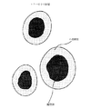
このシアントナー粒子の断面をTEMにより観測したところ、図1に示すように離型剤(ワックス)が外殻樹脂で良好に内包化されていることが確認できた。
【0175】
得られたシアントナー粒子100質量部と、一次粒径9nmのシリカにヘキサメチルジシラザンで処理をした後シリコーンオイルで処理し、処理後のBET値が200m2/gの疎水性シリカ微粉体1.2質量部とを混合し、負摩擦帯電性のシアントナー1を得た。
【0176】
このシアントナー6質量部に対し、アクリルコートされたフェライトキャリア94質量部を混合して現像剤を調製し、図3に示すような市販のデジタルフルカラー複写機(CLC500,キヤノン製)の改造機(定着器のオイル塗布機構を除いた)を用いて、シアントナーの1万枚連続通紙試験(常温常湿(23℃,60%RH)環境下、及び高温高湿(30℃、80%RH)環境下)を行った。トナーの物性及び評価結果を表1、表2及び表3に示す。
【0177】
<実施例2〜4>
実施例1の着色剤をC.I.ピグメントイエロー180、C.I.ピグメントレッド122、カーボンブラックにそれぞれ変更し、実施例1と同様の操作を行い、イエロートナー2、マゼンタトナー3、ブラックトナー4を得た。これらトナー粒子の断面をTEMにより観測したところ、図1に示すように離型剤が外殻樹脂で良好に内包化されていることが確認できた。トナーの物性及び評価結果を表1、表2及び表3に示す。
【0178】
<実施例5>
実施例1の還元剤をジメチルアニリンに変更した以外は実施例1と同様の操作を行い、シアントナー5を得た。このトナー粒子の断面をTEMにより観測したところ、図1に示すように離型剤が外殻樹脂で良好に内包化されていることが確認できた。トナーの物性及び評価結果を表1、表2及び表3に示す。
【0179】
<実施例6>
実施例1の還元剤を亜硫酸ナトリウムに変更した以外は実施例1と同様の操作を行い、シアントナー6を得た。このトナー粒子の断面をTEMにより観測したところ、図1に示すように離型剤が外殻樹脂で良好に内包化されていることが確認できた。トナーの物性及び評価結果を表1、表2及び表3に示す。
【0180】
<実施例7>
(疎水性酸化鉄1の製造)
硫酸第一鉄水溶液中に、鉄イオンに対して1.0〜1.1当量の苛性ソーダ溶液を混合し、水酸化第一鉄を含む水溶液を調製した。
【0181】
水溶液のpHを9前後に維持しながら、空気を吹き込み、80〜90℃で酸化反応を行い、種晶を生成させるスラリー液を調製した。
【0182】
次いで、このスラリー液に当初のアルカリ量(苛性ソーダのナトリウム成分)に対し0.9〜1.2当量となるよう硫酸第一鉄水溶液を加えた後、スラリー液をpH8前後に維持して、空気を吹込みながら酸化反応をすすめ、酸化反応後に生成した磁性酸化鉄粒子を洗浄、濾過して一旦取り出した。この時、含水サンプルを少量採取し、含水量を計っておいた。次に、この含水サンプルを乾燥せずに別の水系媒体中に再分散させた後、再分散液のpHを約6に調製し、充分撹拌しながらシランカップリング剤(n−C6H13Si(OCH3)3)を磁性酸化鉄100質量部に対し3.0質量部(磁性酸化鉄の量は含水サンプルから含水量を引いた値として計算した)添加し、カップリング処理を行った。生成した疎水性酸化鉄粒子を常法により洗浄、濾過、乾燥し、次いで若干凝集している粒子を解砕処理して、平均粒径0.19μmの疎水性酸化鉄1を得た。
【0183】
(磁性トナー7の製造)
イオン交換水710gに0.1M−Na3PO4水溶液448gを投入し60℃に加温した後、1.0M−CaCl2水溶液67.5gを添加してCa3(PO4)2を含む水系媒体を得た。
【0184】
・スチレン 81質量部
・2−エチルヘキシルアクリレート 19質量部
・トリエチレングリコールジメタクリレート 1.0質量部
・ビスフェノールAのP.O及びE.O付加ものとテレフタル酸の縮合反応により得られる飽和ポリエステル樹脂 4質量部
・負荷電性制御剤(モノアゾ染料系のFe化合物) 1質量部
・疎水性酸化鉄1 85質量部
上記処方をアトライター(三井三池化工機(株))を用いて均一に分散混合し、次いでこの分散混合物を60℃に加温し、そこにエステルワックス(融点80℃)12質量部を添加混合し重合性単量体組成物を得た。
【0185】
そしてこれに、重合開始剤2,2’−アゾビス(2,4−ジメチルバレロニトリル)5部及びt−ブチルパーオキシピバレート2部を溶解後、前記水系媒体中に上記重合性単量体組成物を投入し、60℃,N2雰囲気下においてTK式ホモミキサー(特殊機化工業(株))にて10,000rpmで10分間撹拌し、造粒した。その後パドル撹拌翼で撹拌しつつ、60℃で2時間反応させた。その後液温を80℃とし、更に7時間継続して撹拌し重合反応を完了させたが、該重合反応時、重合体の重量平均分子量(Mw)が210000、重合転化率が98.2%の時、レドックス開始剤用還元剤としてアスコルビン酸ナトリウム4質量部を添加した。反応終了後、蒸留を行い、その後、懸濁液を冷却し、塩酸を加えて分散剤を溶解し、濾過,水洗,乾燥して重合磁性トナー粒子を得た。
【0186】
この黒色粒子100質量部と、一次粒径9nmのシリカにヘキサメチルジシラザンで処理をした後シリコーンオイルで処理し、処理後のBET値が200m2/gの疎水性シリカ微粉体1.0質量部とを混合し、磁性トナー7を得た。
【0187】
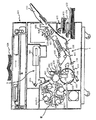
この磁性トナー7を用い、図7に示す磁性一成分現像装置(LBP−1760(キヤノン製))を用い、1万枚連続通紙試験(常温常湿(23℃,60%RH)環境下、及び高温高湿(30℃,80%RH)環境下)を行った。磁性トナー7の物性及び評価結果を表1、表2及び表3に示す。
【0188】
<実施例8>
実施例1のアスコルビン酸ナトリウムを添加するときの重合体の重量平均分子量を開始剤の量や重合反応温度を変更することにより9000にする以外は実施例1と同様の操作を行い、シアントナー8を得た。これらトナー粒子の断面をTEMにより観測したところ、図1に示すように離型剤が外殻樹脂で良好に内包化されていることが確認できた。トナーの物性及び評価結果を表1、表2及び表3に示す。
【0189】
<実施例9>
実施例1のアスコルビン酸を添加するときの重合体の重量平均分子量を開始剤の量や重合反応温度を変更することにより1510000にする以外は実施例1と同様の操作を行い、シアントナー9を得た。これらトナー粒子の断面をTEMにより観測したところ、図1に示すように離型剤が外殻樹脂で良好に内包化されていることが確認できた。トナーの物性及び評価結果を表1、表2及び表3に示す。
【0190】
<実施例10>
実施例1のt−ブチルパーオキシピバレートをt−ブチルパーオキシ−2−エチルヘキサノエートに変更する以外は実施例1と同様の操作を行い、シアントナー10を得た。これらトナー粒子の断面をTEMにより観測したところ、図1に示すように離型剤が外殻樹脂で良好に内包化されていることが確認できた。トナーの物性及び評価結果を表1、表2及び表3に示す。
【0191】
<実施例11>
実施例1のt−ブチルパーオキシピバレートを、t−ブチルパーオキシイソブチレートに変更する以外は実施例1と同様の操作を行い、シアントナー11を得た。これらトナー粒子の断面をTEMにより観測したところ、図1に示すように離型剤が外殻樹脂で良好に内包化されていることが確認できた。トナーの物性及び評価結果を表1、表2及び表3に示す。
【0192】
<実施例12>
実施例1のt−ブチルパーオキシピバレートを、ラウロイルパーオキサイドに変更する以外は実施例1と同様の操作を行い、シアントナー12を得た。これらトナー粒子の断面をTEMにより観測したところ、図1に示すように離型剤が外殻樹脂で良好に内包化されていることが確認できた。トナーの物性及び評価結果を表1、表2及び表3に示す。
【0193】
<実施例13>
実施例1のt−ブチルパーオキシピバレートを、ジ−2−エチルヘキシルパーオキシジカーボネートに変更する以外は実施例1と同様の操作を行い、シアントナー13を得た。これらトナー粒子の断面をTEMにより観測したところ、図1に示すように離型剤が外殻樹脂で良好に内包化されていることが確認できた。トナーの物性及び評価結果を表1、表2及び表3に示す。
【0194】
<実施例14>
実施例1のエステルワックスの添加部数を0.5質量部に変更した以外は実施例1と同様の操作を行い、シアントナー14を得た。トナーの物性及び評価結果を表1、表2及び表3に示す。
【0195】
<実施例15>
実施例1のエステルワックスの添加部数を33質量部に変更した以外は実施例1と同様の操作を行い、シアントナー15を得た。これらトナー粒子の断面をTEMにより観測したところ、離型剤が外殻樹脂で良好に内包化されていることが確認できた。トナーの物性及び評価結果を表1、表2及び表3に示す。
【0196】
<実施例16>
実施例1のエステルワックスをポリエチレンを主体とするワックス(融点115℃)に変更した以外は実施例1と同様の操作を行い、シアントナー16を得た。これらトナー粒子の断面をTEMにより観測したところ、図1に示すように離型剤が外殻樹脂で良好に内包化されていることが確認できた。トナーの物性及び評価結果を表1、表2及び表3に示す。
【0197】
<実施例17>
分散媒反応容器中のイオン交換水1000質量部に、リン酸ナトリウム14質量部ならびに10%塩酸を4.5質量部投入し、N2パージしながら65℃で60分保温した。TK式ホモミキサー(特殊機化工業製)を用いて、12000rpmにて撹拌しながら、イオン交換水10質量部に8質量部の塩化カルシウムを溶解した塩化カルシウム水溶液を一括投入し、分散安定剤を含む水系媒体を調製した。
【0198】
重合性単量体組成物
・スチレン 60質量部
・着色剤(カーボンブラック) 7質量部
・負荷電性制御剤(モノアゾ染料系のFe化合物) 1.0質量部
上記材料をアトライター分散機(三井三池化工機株式会社)に投入し、さらに直径2mmのジルコニア粒子を用いて、220rpmで5時間分散させて、重合性単量体混合物を得た。
【0199】
上記重合性単量体混合物に更に
・スチレン 22質量部
・2−エチルヘキシルアクリレート 18質量部
・ポリエステル樹脂 8質量部
(飽和ポリエステル(イソフタル酸−プロピレンオキサイド変性ビスフェノールA))
・エステルワックス(融点80℃) 4質量部
・ジビニルベンゼン 0.6質量部
を加え重合性単量体組成物を得た。
【0200】
別容器中で上記重合性単量体組成物を65℃に保温し、TK式ホモミキサー(特殊機化工業製)を用いて、500rpmにて均一に溶解、分散した。これに、重合開始剤2,2’−アゾビス(2,4−ジメチルバレロニトリル)5部及びt−ブチルパーオキシピバレート5部を溶解し、次いで反応容器中の上記水系媒体中に投入し、65℃,N2パージ下において、TK式ホモミキサーにて10000rpmで5分間撹拌し、造粒した。その後、パドル撹拌翼で撹拌しつつ65℃で6時間撹拌後、さらに80℃に昇温し、更に5時間継続して撹拌し重合反応を完了させたが、該重合反応時、重合体の重量平均分子量(Mw)が250000、重合転化率が99.7%の時、レドックス開始剤用還元剤としてアスコルビン酸ナトリウム4質量部を添加した。
【0201】
重合反応終了後、反応容器を冷却し、10%塩酸を加えpH=2の状態で2時間撹拌しながら分散安定剤を溶解させる。そのエマルションを加圧濾過しさらに2000質量部以上のイオン交換水で洗浄する。得られたケーキを1000質量部のイオン交換水に戻し、10%塩酸を加えpH=2の状態で2時間撹拌する。上記と同様にこのエマルションを加圧濾過し得られたケーキを再び1000質量部のイオン交換水に戻し、このエマルションに6%の塩化アルミニウム水溶液100質量部を添加し凝集させる。その後加圧濾過を用いてさらに2000質量部以上のイオン交換水で濾過洗浄し、同濾過機上で得られたケーキに90℃の温水3000質量部を添加し温水加熱処理を行ったところ、粒子同士が融着してなるブロック状物の塊状物を形成した。40℃で乾燥後、このブロック状物を粗砕し、ハンマーミルにて粗砕して、目開き1mmの篩を通過させたトナー粗砕物をさらにジェット気流を利用した衝突式粉砕機で微粉砕した後、風力分級し、これ以外は実施例1と同様にしブラックトナー17を得て分析評価した。トナーの物性及び評価結果を表1、表2及び表3に示す。
【0202】
<実施例18>
実施例1で使用したトナーを用い、図4に示すような非磁性一成分現像方式の装置を用いて、フルカラー1万枚連続通紙試験(常温常湿(23℃,60%RH)環境下、及び高温高湿(30℃,80%RH)環境下)を行った。評価結果を表2及び表3に示す。ベタ均一性のある安定した画質が得られた。
【0203】
<比較例1>
実施例1のアスコルビン酸ナトリウムを添加するときの重合体のスチレン重合転化率を97.8%にする以外は実施例1と同様の操作を行い、シアントナー18を得た。トナーの物性及び評価結果を表1、表2及び表3に示す。
【0204】
<比較例2>
実施例1において、還元剤を使用しなかった以外は実施例1と同様の操作を行い、シアントナー19を得た。トナーの物性及び評価結果を表1、表2及び表3に示す。
【0205】
【表1】
【表2】
【表3】
【発明の効果】
本発明のトナーを用いることにより、帯電均一性に優れ、良好な定着性を有し、長期の使用においても画像濃度が高く、カブリやゴーストも生じず、トナー融着も発生しない高精細な画像が得られる。
【図面の簡単な説明】
【図1】離型剤が外殻樹脂に内包化されているトナー粒子の断面の模式図である。
【図2】本発明のトナーが適用され得る現像装置の概略図である。
【図3】フルカラー又はマルチカラーの画像形成方法を説明するための概略図である。
【図4】中間転写体使用の画像形成方法の概略図である。
【図5】磁性一成分現像装置を示す概略図である。
【図6】磁性一成分現像装置を示す概略図である。
【図7】磁性一成分現像装置を示す概略図である。
【符号の説明】
31 現像剤担持体(現像スリーブ)
32 現像剤規制部材
33 静電荷像保持体(感光ドラム)
45 加熱ローラ
46 加圧ローラ
100 感光体(像担持体、被帯電体)
102 現像スリーブ(磁性トナー担持体)
114 転写ローラー(転写部材)
116 クリーナー
117 帯電ローラー(接触帯電部材)
121 レーザービームスキャナー(潜像形成手段、露光装置)
124 給紙ローラー
125 搬送部材
126 定着装置
140 現像装置
141 撹拌部材[0001]
BACKGROUND OF THE INVENTION
The present invention relates to a toner for developing an electrostatic latent image and a toner manufacturing method using electrophotography, electrostatic recording, toner jet recording, and the like.
[0002]
[Prior art]
Conventionally, a number of methods are known as electrophotographic methods. In general, an electric latent image is formed on an electrostatic image carrier (hereinafter also referred to as a photoreceptor) by various means using a photoconductive substance. Then, the latent image is developed with toner to form a visible image. If necessary, the toner image is transferred to a transfer material such as paper, and then the toner image is fixed on the transfer material by heat and pressure. To obtain a copy.
[0003]
Also, LED and LBP printers are the mainstream in the recent market as printer devices, and the direction of technology is higher resolution, that is, what was conventionally 240, 300 dpi is 400, 600, 800 dpi. Accordingly, with this development, higher definition has been demanded. In addition, copiers are also becoming more sophisticated, and therefore are moving toward digitalization. Since this method is mainly a method of forming an electrostatic latent image with a laser, it is also proceeding in the direction of high resolution, and here again, a high-resolution and high-definition development method is required as in the case of a printer. Yes. As one means for satisfying this requirement, toner particle size reduction is progressing, and Patent Documents 1 to 6 propose a toner having a specific particle size distribution and a small particle size.
[0004]
Thus, in recent years, progress has been made in the direction of reducing the particle size of the toner for high resolution and high definition, but as the toner particle size becomes smaller in this way, stable triboelectric charging of the toner powder becomes an important technology. . In other words, unless the fine individual toner particles have a uniform charge amount, the above-described decrease in image stability tends to be more noticeable. This is because the toner particle size is simply reduced, and the adhesion force (mirror image force, van der Waals force, etc.) of the toner particles to the photoreceptor is larger than the Coulomb force applied to the toner particles in the transfer process. As a result, in addition to the increase in the residual toner, the reduction in the toner diameter is accompanied by a deterioration in fluidity, so that the charge amount of individual toner particles tends to be non-uniform, resulting in fog and toner particles having poor transferability. This is because it increases.
[0005]
Due to this background, it is indispensable to maintain more stable charging characteristics in order to improve toner performance. Factors that determine toner charging are broadly divided into the amount of charge generated when the toner particles rub against each other, the amount of charge generated when the toner particles rub or contact with the external member, and the like. The surface material and the size and shape of the toner particles, external additives for the purpose of assisting charging, regulating members using metal or rubber materials, and the charge control agent that is a constituent material of the toner particles are greatly involved. .
[0006]
For example, metal compounds of aromatic carboxylic acids such as salicylic acid, alkyl salicylic acid, dialkyl salicylic acid, naphthoic acid, dicarboxylic acid, metal salts or metal complexes of azo dyes or azo pigments, sulfonic acid or carboxylic acid groups as negative charge control agents High molecular compound having a side chain, boron compound, urea compound, silicon compound, calixarene, and quaternary ammonium salt as a positive charge control agent, high molecular compound having the quaternary ammonium salt in the side chain, guanidine Various charge control agents such as compounds, nigrosine compounds, and imidazole compounds and their existence states are disclosed in Patent Documents 7 to 10 and the like. However, the techniques disclosed in these publications are still insufficient in charge uniformity because the charge control agent is randomly scattered in the toner particles.
[0007]
On the other hand, in recent years, a charge control agent of a polar polymer has been attracting attention because it is excellent in compatibility with other components and can be uniformly charged. In Patent Documents 11 to 17, a sulfonic acid group or a similar functional group is added. It is disclosed as a toner using a monomer contained as an essential component. However, although these charge control agents have a certain level of performance in charging, the control agent itself also affects the dispersibility of the colorant in the toner and the toner fluidity, so that the amount sufficient for charging is sufficient. In addition, it has been found that excessive slip occurs, resulting in a toner having a wide charge distribution, and when these polar polymer charge control agents and inorganic metal complex charge control agents are used in combination. Is a toner having a particularly wide charge distribution because each charge control agent develops its charging performance due to its chemical structure.
[0008]
Furthermore, a method of adding inorganic fine particles as external additives to toner base particles has been proposed and widely used in order to improve the above problems and to obtain good toner flow characteristics, charging characteristics, and the like.
[0009]
For example, inorganic fine particles that have been hydrophobized in Patent Documents 18 and 19 or inorganic fine particles that have been hydrophobized and then treated with silicone oil or the like are added. Hydrophobized inorganic particles and silicone oil treated in Patent Documents 20 and 21 A method of adding inorganic fine particles in combination is known.
[0010]
However, even if such improvement means is used, it is not sufficient to sufficiently bring out the performance in terms of both the fluidity and the chargeability, and as a result, there is a sufficient improvement effect in image characteristics and durability. Is hard to say.
[0011]
On the other hand, various proposals have been made so far for improving the toner fixing property. For example, Patent Documents 22 to 24 disclose that wax is contained in toner particles.
[0012]
Waxes are used to improve offset resistance at low temperature fixing or high temperature fixing of toner, and to improve fixability at low temperature fixing. On the other hand, the toner's blocking resistance is lowered, the developing property of the toner is lowered due to the temperature rise in the machine, and the wax migrates to the toner particle surface when the toner is left for a long time under high temperature and high humidity. The sex will be reduced.
[0013]
Toners produced by suspension polymerization have been proposed for the above problems. For example, according to Patent Document 25, when a polar component is added to a monomer composition in an aqueous dispersion medium, the component having a polar group contained in the monomer composition is a surface layer that is an interface with the aqueous phase. Therefore, non-polar components are less likely to be present in the surface layer portion, so that the toner particles can have a core / shell structure.
[0014]
As a result, the produced toner can have both conflicting performances of blocking resistance and high temperature offset resistance by encapsulating wax in the toner particles, and a release agent such as oil is used for the fixing roller. It becomes possible to prevent high temperature offset without coating.
[0015]
However, with regard to low-temperature fixability, an important issue is how quickly the wax in the core portion of the toner having a core / shell structure exudes to the toner surface layer during fixing.
[0016]
Further, in Patent Document 26, in a method for producing a polymerized toner, suspension polymerization is performed in the presence of an oil-soluble polymerization initiator, and then a reducing agent for redox initiator is added, whereby low-temperature fixability and anti-blocking property are added. We propose to achieve both. However, although this effect is satisfied to some extent, in the publication, the addition time of the reducing agent for redox initiator is added as early as the polymerization conversion rate of 30 to 97%, and when the reducing agent for redox initiator is added. At the same time, since the polymerizable monomer is added, not only the uniformity of charging is impaired due to the locally generated ultra-low molecular weight but also the presence of the ultra-low molecular weight component in the vicinity of the surface layer of the toner particles. It has been found that toner fusion occurs in a high temperature and high humidity environment.
[0017]
Patent Document 27 discloses a technique for a toner produced by agglomerating polymer primary particles obtained by seed polymerization of a wax emulsion using a redox initiator, and the polymer primary particles are a wax. It has been proposed that the fixing region is expanded by substantially including the above. However, it has been found that the decomposition of the initiator locally occurs due to the addition of the reducing agent for the redox initiator simultaneously with the initiator, thereby generating an ultra-low molecular weight component and causing toner fusion.
[0018]
As described above, there is a demand for a toner that can sufficiently satisfy low temperature fixability and toner fusion suppression in addition to developability and transferability.
[0019]
[Patent Document 1]
Japanese Patent Laid-Open No. 1-112253
[Patent Document 2]
JP-A-1-191156
[Patent Document 3]
JP-A-2-214156
[Patent Document 4]
JP-A-2-284158
[Patent Document 5]
Japanese Patent Laid-Open No. 3-181952
[Patent Document 6]
JP-A-4-162048
[Patent Document 7]
JP-A-4-303850
[Patent Document 8]
JP-A-6-138707
[Patent Document 9]
JP-A-6-348055
[Patent Document 10]
Japanese Patent Laid-Open No. 7-20657
[Patent Document 11]
Japanese Patent Laid-Open No. 3-15858
[Patent Document 12]
JP-A-3-56974
[Patent Document 13]
JP-A-8-179564
[Patent Document 14]
Japanese Patent Laid-Open No. 11-184165
[Patent Document 15]
JP-A-11-28126
[Patent Document 16]
Japanese Patent Laid-Open No. 11-327208
[Patent Document 17]
JP 2000-56518 A
[Patent Document 18]
JP-A-5-66608
[Patent Document 19]
Japanese Patent Laid-Open No. 4-9860
[Patent Document 20]
JP-A-4-264453
[Patent Document 21]
JP-A-5-346682
[Patent Document 22]
Japanese Patent Laid-Open No. 3-50559
[Patent Document 23]
Japanese Patent Laid-Open No. 2-79860
[Patent Document 24]
JP-A-1-109359
[Patent Document 25]
JP-A-5-341573
[Patent Document 26]
JP-A-11-202553
[Patent Document 27]
JP 2001-27821 A
[0020]
[Problems to be solved by the invention]
An object of the present invention is to provide a toner production method that solves the above-described problems of the prior art and a polymerized toner produced by the method.
[0021]
That is, an object of the present invention is a method for producing a toner that is excellent in charging stability, has good low-temperature fixability, does not cause toner fusion even in a high-temperature and high-humidity environment, and provides a high-definition image, and It is to provide a polymerized toner produced by the method.
[0022]
[Means for Solving the Problems]
The present invention provides a method for producing a polymerized toner comprising polymerizing a polymerizable monomer composition containing at least a colorant, wherein the polymerization conversion rate of the polymerizable monomer composition is 98.~ 99.7%The present invention relates to a method for producing a polymerized toner, wherein a reducing agent for redox initiator is added, and a polymerized toner produced by the method.
[0023]
DETAILED DESCRIPTION OF THE INVENTION
As a result of intensive studies by the present inventors, in a method for producing a polymerized toner that polymerizes a polymerizable monomer composition containing at least a colorant, the polymerization conversion rate of the polymerizable monomer composition is 98%. As described above, it has been found that the addition of the reducing agent for redox initiator is effective for the charging stability of the polymerized toner and the toner fusion suppression.
[0024]
In order to obtain a high-definition image, a small particle size toner is advantageous. However, in order to appropriately control the charge amount of the toner having a small particle size and to improve fog, ghost, and developability, as shown in the present invention, the toner particles when the reducing agent for redox initiator is added. The polymerization conversion of is very important.
[0025]
Specifically, the polymerization conversion rate of the polymerizable monomer composition is 98% or more, and it is essential to add the reducing agent for redox initiator.
[0026]
The reason why it is essential to add a reducing agent for redox initiator when the polymerization conversion rate is higher than this is not clarified in detail, but a reducing agent for redox initiator having a high polarity is an oxidizing agent (initiator). Is taken into the toner particles at the time of reaction with the toner particles, and is present in the vicinity of the toner particle surface layer. ing.
[0027]
If the polymerization conversion rate is less than 98%, a large amount of monomer is present in the toner particles. Therefore, by adding a reducing agent for redox initiator within the range of the polymerization conversion rate, the viscoelasticity of the toner particles is increased. Therefore, the added reducing agent for redox initiator easily moves into the toner and is embedded in the toner. Furthermore, the presence of ultra-low molecular weight components also tends to increase, and as a result, the chargeability of the toner tends to be non-uniform. Furthermore, it is considered that toner fusion is likely to occur in a high temperature and high humidity environment.
[0028]
Moreover, it is preferable to add the reducing agent for redox initiators when it is in the range of 10,000 ≦ Mw ≦ 1500000.
[0029]
When Mw <10000, the viscosity of the toner particles tends to be low, and it becomes difficult for the reducing agent for redox initiator to be present in the vicinity of the toner surface layer. Furthermore, the addition of the reducing agent for redox initiator in the molecular weight range not only makes the ultra-low molecular weight component locally present in the toner particles, but also tends to make the chargeability of the toner particles non-uniform, especially at high temperatures and high temperatures. It is considered that toner fusing is likely to occur due to continuous printing in a wet environment. Further, when Mw> 1500000, the rigidity of the particle surface is likely to increase, so that the redox reducing agent is not easily taken into the toner particle, so that the chargeability of the toner particle is likely to be non-uniform and the low-temperature fixability is likely to be impaired. I believe.
[0030]
Further, the toner of the present invention preferably polymerizes the polymerizable monomer composition by using an organic peroxide having a 10-hour half-life temperature exceeding 50 ° C. as the polymerization initiator. When an organic peroxide of 50 ° C. or less is used as an initiator, the reaction is difficult to control due to the remarkable decomposition rate of the initiator, and there is a strong tendency to have ultra-low molecular weight components locally in the toner particles. In some cases, it may cause drum fusion in a high temperature and high humidity environment.
[0031]
Further, the organic peroxide initiator is t-butyl peroxypivalate (10-hour half-life temperature 54.6 ° C.), t-butyl peroxy-2-ethylhexanoate (10-hour half-life temperature 72. 1 ° C.) and t-butyl peroxyisobutyrate (10-hour half-life temperature 77.3 ° C.).
[0032]
This is presumably because these organic peroxides are decomposed and a part thereof produces t-butanol by a hydrogen abstraction reaction, thereby being more uniformly dispersed in the toner binder resin. As a result of intensive studies by the present inventors, it is effective that a very small amount of t-butanol is contained in the toner in order to allow the wax existing in the toner to exude to the toner surface layer instantaneously at the time of fixing. It has been found. The reason why t-butanol is effective is that since the melting point is about 26 ° C., which is close to normal temperature, it dissolves instantaneously at the time of fixing, so that it acts as a plasticizer, and the wax tends to exude to the toner surface layer.
[0033]
In the present invention, the content of t-butanol in the toner is preferably 0.1 to 1000 ppm. If the content is less than 0.1 ppm, the above effect is insufficient. If the content exceeds 1000 ppm, the toner blocking resistance and fluidity deteriorate under high temperature and high humidity, or the toner is fused to the charging member or the photoreceptor. Is likely to occur.
[0034]
The content of t-butanol in the toner of the present invention is easily measured by an internal standard method by preparing a calibration curve by gas chromatography.
[0035]
In addition, as a reducing agent used in the present invention, Fe2+Examples include salts, sulfites, alcohols, amines (polyamines, tertiary amines), naphthenates, mercaptans, etc. Among them, organic compounds that do not contain sulfur or nitrogen elements are preferable, and further, ascorbic acid More preferred is a salt of This is because the chargeability of the toner tends to deteriorate when organic compounds having sulfur or nitrogen atoms remain in the toner. In particular, in the case of a negative toner, if an organic compound containing a nitrogen atom remains, it is not preferable for chargeability. When a salt of ascorbic acid is used as the reducing agent, the effect of a dispersion stabilizer is also obtained during the polymerization reaction in an aqueous medium, and the particle size distribution of the toner particles obtained is preferable because it is very sharp.
[0036]
The toner of the present invention preferably contains a wax in order to improve fixability. It is preferable to contain 1-30 mass% with respect to binder resin. More preferably, it is 3 to 25% by mass. When the content of the wax is less than 1% by mass, the effect of adding the wax is not sufficient, and further, the effect of suppressing the offset is insufficient. On the other hand, if it exceeds 30% by mass, the long-term storage stability is deteriorated and the dispersibility of the toner material such as the colorant is deteriorated, leading to deterioration of the coloring power of the toner and deterioration of image characteristics. In addition, the exudation of the wax is likely to occur, and the durability under high temperature and high humidity is inferior. Further, since a large amount of wax is included, the toner shape tends to become distorted.
[0037]
Examples of the release agent usable in the toner of the present invention include petroleum waxes such as paraffin wax, microcrystalline wax, petrolactam and derivatives thereof, montan wax and derivatives thereof, hydrocarbon waxes and derivatives thereof by Fischer-Tropsch method, polyethylene And natural waxes and derivatives thereof such as carnauba wax and candelilla wax, which include oxides, block copolymers with vinyl monomers, and graft modified products. Furthermore, fatty acids such as higher aliphatic alcohols, stearic acid and palmitic acid, or compounds thereof, acid amide waxes, ester waxes, ketones, hydrogenated castor oil and derivatives thereof, plant waxes, animal waxes and the like can also be used.
[0038]
Among these waxes, those having a maximum endothermic peak in the region of 40 to 110 ° C. at the time of temperature rise in the DSC curve measured by the differential scanning calorimeter are preferable, and more preferably those in the region of 50 to 100 ° C. preferable. By having the maximum endothermic peak in the above temperature range, in combination with the effect of t-butanol, it greatly contributes to low-temperature fixing and also effectively exhibits releasability. However, when the maximum endothermic peak is less than 40 ° C., the self-aggregation force of the release agent component becomes weak, and as a result, the high temperature offset resistance deteriorates. In addition, bleeding of the release agent is likely to occur, the toner charge amount is reduced, and durability under high temperature and high humidity is reduced. On the other hand, when the maximum endothermic peak exceeds 110 ° C., the effect of t-butanol is not sufficient, the fixing temperature is increased, and low temperature offset is likely to occur, which is not preferable. Furthermore, when granulating / polymerizing in an aqueous medium and directly obtaining a toner by the polymerization method, if the maximum endothermic peak temperature is high, problems such as precipitation of a release agent component mainly occur during granulation. Graininess tends to deteriorate, which is not preferable.
[0039]
The endothermic amount of the release agent and the maximum endothermic peak temperature are measured according to “ASTM D 3418-8”. For the measurement, for example, DSC-7 manufactured by PerkinElmer is used. The temperature correction of the device detection unit uses the melting points of indium and zinc, and the correction of heat uses the heat of fusion of indium. An aluminum pan is used as a measurement sample, and an empty pan is set as a control. The sample is heated up to 200 ° C. once to remove the heat history, then rapidly cooled, and again at a heating rate of 10 ° C./min. DSC curve measured when the temperature is raised in the range of 30 to 200 ° C. is used. The same measurement was performed in the examples described later, and the peak temperature was defined as the melting point.
[0040]
In the present invention, in order to obtain further excellent transferability and good charging performance, the toner shape is preferably spherical. Specifically, the average circularity of the toner needs to be 0.970 or more, and as a result, the contact area between the toner particles and the photosensitive member is reduced, which is caused by mirror image force, van der Waals force, or the like. Since the adhesion force of the toner particles to the photoreceptor is reduced, the toner particles are easily transferred. Furthermore, since it has a high circularity and a shape close to a sphere, it is particularly excellent in charging uniformity because it is easy to uniformly rub the entire surface when compared with an irregular toner having irregularities.
[0041]
At this time, the mode circularity is more preferably 0.99 or more in the circularity distribution of the toner. When the mode circularity is 0.99 or more, it means that most of the toner particles have a shape close to a true sphere, and the above action becomes more remarkable, and the triboelectric charging characteristics and transferability are further improved. . Here, the “mode circularity” means that the circularity is 0.40 to 1.00 divided by 61 every 0.01, and the measured circularity of the toner is assigned to each divided range according to the circularity. This is the lower limit value of the division range in which the frequency value is maximum in the circularity frequency distribution.
[0042]
The toner of the present invention is produced by a polymerization method, but is particularly preferably produced by a suspension polymerization method. The polymerized toner of the present invention can be directly polymerized in the presence of a water-soluble polar polymerization initiator by a dispersion polymerization method in which a toner is produced directly using an aqueous organic solvent that is soluble in the monomer and insoluble in the resulting polymer. Although it is possible to produce a toner by using an emulsion polymerization method represented by a soap-free polymerization method for producing a toner, in any of these production methods, an average circle which is a preferable requirement of the toner according to the present invention In order to obtain a physical property of a degree of 0.970 or more, the use of a large amount of organic solvent in the manufacturing process and the operation on the process such as mechanical / thermal or some special treatment are necessary, which increases the cost. Sometimes.
[0043]
Therefore, in order to solve the above-described problems, it is preferable that the polymerized toner is produced by the suspension polymerization method in the present invention. In this suspension polymerization method, a monomer composition is prepared by uniformly dissolving or dispersing a polymerizable monomer and a colorant (and, if necessary, a polymerization initiator, a crosslinking agent, a charge control agent, and other additives). Then, the monomer composition is dispersed in a continuous phase (for example, an aqueous phase) containing a dispersion stabilizer using a suitable stirrer, and simultaneously polymerized to obtain toner particles having a desired particle size. Is what you get. Since the toner particles obtained by this suspension polymerization method have individual toner particle shapes that are substantially spherical, it is easy to obtain a toner satisfying the preferable requirements of the present invention with an average circularity of 0.970 or more. Such a toner has a high transferability because the distribution of charge amount is relatively uniform.
[0044]
In the production of the polymerized toner of the present invention, examples of the polymerizable monomer constituting the polymerizable monomer composition include the following.
[0045]
Examples of the polymerizable monomer include styrene monomers such as styrene, o-methylstyrene, m-methylstyrene, p-methylstyrene, p-methoxystyrene, p-ethylstyrene, methyl acrylate, ethyl acrylate, Acrylate esters such as n-butyl acrylate, isobutyl acrylate, n-propyl acrylate, n-octyl acrylate, dodecyl acrylate, 2-ethylhexyl acrylate, stearyl acrylate, 2-chloroethyl acrylate, and phenyl acrylate , Methyl methacrylate, ethyl methacrylate, n-propyl methacrylate, n-butyl methacrylate, isobutyl methacrylate, n-octyl methacrylate, dodecyl methacrylate, 2-ethylhexyl methacrylate, stearyl methacrylate, phenyl methacrylate, Methacrylic acid dimethyl aminoethyl, methacrylic acid esters other acrylonitrile such as diethylaminoethyl methacrylate, methacrylonitrile, and the like monomers acrylamide. These monomers can be used alone or in combination. Among the above-mentioned monomers, styrene or a styrene derivative is preferably used alone or mixed with other monomers from the viewpoint of the developing characteristics and durability of the toner.
[0046]
In the production of the polymerized toner of the present invention, the polymerization may be carried out by adding a resin to the polymerizable monomer composition. For example, it contains hydrophilic functional groups such as amino groups, carboxylic acid groups, hydroxyl groups, sulfonic acid groups, glycidyl groups, and nitrile groups that cannot be used because monomers are water-soluble and dissolve in aqueous suspension to cause emulsion polymerization. When it is desired to introduce the polymerizable monomer component into the toner, a random copolymer of these and a vinyl compound such as styrene or ethylene, a block copolymer, or a graft copolymer, and the like, Alternatively, it can be used in the form of a polycondensate such as polyester or polyamide, or a polyaddition polymer such as polyether or polyimine. When such a polymer containing a polar functional group is allowed to coexist in the toner, the above-described wax component is phase-separated, the encapsulation becomes stronger, and a toner having good blocking resistance and developability can be obtained.
[0047]
Among these resins, the effect is greatly increased by containing a polyester resin. I think this is because of the following reasons. Since the polyester resin contains many ester bonds which are functional groups having relatively high polarity, the polarity of the resin itself is increased. Due to its polarity, the tendency of the polyester to be unevenly distributed on the surface of the droplets in the aqueous dispersion medium becomes strong, and the polymerization proceeds while maintaining this state, resulting in a toner. For this reason, the polyester resin is unevenly distributed on the toner surface, so that not only the surface state and the surface composition become uniform, but also the above-mentioned reducing agent is strongly interacted with the reducing agent for the redox initiator. It can be present in the vicinity of the toner particle surface layer. As a result, the chargeability becomes uniform, and a very good developability can be obtained by a synergistic effect with the good inclusion property of the release agent.
[0048]
Furthermore, if a polymer having a molecular weight different from the molecular weight range of the toner obtained by polymerizing the polymerizable monomer is dissolved in the monomer and polymerized, a toner having a wide molecular weight distribution and high offset resistance can be obtained. I can do it.
[0049]
As the polymerization initiator used in the present invention, conventionally known azo polymerization initiators, peroxide polymerization initiators and the like may be used in combination. As the azo polymerization initiator, 2,2′-azobis- (2,4-dimethylvaleronitrile), 2,2′-azobisisobutyronitrile, 1,1′-azobis (cyclohexane-1-carbonitrile) ), 2,2′-azobis-4-methoxy-2,4-dimethylvaleronitrile, azobisisobutyronitrile, etc., and examples of the peroxide polymerization initiator include t-butyl hydroperoxide, di- t-butyl hydroperoxide, t-butyl peroxyisopropyl monocarbonate, t-butyl peroxyacetate, t-butyl peroxylaurate, t-butyl peroxypivalate, t-butyl peroxy-2-ethylhexano Ate, t-butylperoxyisobutyrate, t-butylperoxyneodecanoate, t-hexylpa Oxyacetate, t-hexylperoxylaurate, t-hexylperoxypivalate, t-hexylperoxy-2-ethylhexanoate, t-hexylperoxyisobutyrate, t-hexylperoxyneodecanoate , T-butylperoxybenzoate, α, α′-bis (neodecanoylperoxy) diisopropylbenzene, cumylperoxyneodecanoate, 1,1,3,3-tetramethylbutylperoxy-2-ethylhexa Noate, 1,1,3,3-tetramethylbutylperoxyneodecanoate, 1-cyclohexyl-1-methylethylperoxyneodecanoate, 2,5-dimethyl-2,5-bis (2- Ethylhexanoylperoxy) hexane, 1-cyclohexyl-1-methylethylperoxy 2-ethylhexanoate, t-hexylperoxyisopropyl monocarbonate, t-butylperoxy 2-ethylhexyl monocarbonate, t-hexylperoxybenzoate, 2,5-dimethyl-2,5-bis (benzoylperoxy) ) Hexane, t-butylperoxy-m-toluoyl benzoate, bis (t-butylperoxy) isophthalate, t-butylperoxymaleic acid, t-butylperoxy-3,5,5-trimethylhexano , Peroxyesters such as 2,5-dimethyl-2,5-bis (m-toluoylperoxy) hexane, diacyl peroxides such as benzoyl peroxide, lauroyl peroxide, isobutyryl peroxide, diisopropyl peroxide Carbonet Peroxydicarbonate such as bis (4-t-butylcyclohexyl) peroxydicarbonate, 1,1-di-t-butylperoxycyclohexane, 1,1-di-t-hexylperoxycyclohexane, 1, Peroxyketals such as 1-di-t-butylperoxy-3,3,5-trimethylcyclohexane, 2,2-di-t-butylperoxybutane, dicumyl peroxide, t-butylcumyl peroxide, etc. Examples of the dialkyl peroxide include t-butyl peroxyallyl monocarbonate and hydrogen peroxide.
[0050]
As the crosslinking agent used in the present invention, compounds having two or more polymerizable double bonds are mainly used. For example, aromatic divinyl compounds such as divinylbenzene and divinylnaphthalene; for example, ethylene glycol diacrylate Carboxylic acid esters having two double bonds such as ethylene glycol dimethacrylate, 1,3-butanediol dimethacrylate, etc .; divinyl compounds such as divinylaniline, divinyl ether, divinyl sulfide, divinyl sulfone; and three or more A compound having a vinyl group is used alone or as a mixture. The addition amount needs to be adjusted depending on the initiator to be used, the kind of the crosslinking agent, and the reaction conditions, but is generally 0.01 to 5 parts by mass with respect to 100 parts by mass of the polymerizable monomer.
[0051]
As the colorant used in the present invention, a black colorant that is toned in black using carbon black, a magnetic material, and the following yellow / magenta / cyan colorant is used. In the case of a colorant used for a toner produced by a polymerization method, it is necessary to pay attention to the polymerization inhibitory property and water phase transferability of the colorant. The colorant is preferably subjected to surface modification (for example, a hydrophobic treatment without polymerization inhibition). In particular, since dyes and carbon black have many polymerization-inhibiting properties, care must be taken when using them.
[0052]
As the yellow colorant, compounds typified by condensed azo compounds, isoindolinone compounds, anthraquinone compounds, azo metal complexes, methine compounds, and allylamide compounds are used. Specifically, C.I. I. Pigment Yellow 12, 13, 14, 15, 17, 62, 74, 83, 93, 94, 95, 109, 110, 111, 128, 129, 147, 168, 180, etc. are preferably used.
[0053]
As the magenta colorant, condensed azo compounds, diketopyrrolopyrrole compounds, anthraquinones, quinacridone compounds, basic dye lake compounds, naphthol compounds, benzimidazolone compounds, thioindigo compounds, and perylene compounds are used. Specifically, C.I. I.
[0054]
As the cyan colorant used in the present invention, copper phthalocyanine compounds and derivatives thereof, anthraquinone compounds, basic dye lake compounds, and the like can be used. Specifically, C.I. I. Pigment Blue 1, 7, 15, 15: 1, 15: 2, 15: 3, 15: 4, 60, 62, 66 and the like are particularly preferably used.
[0055]
These colorants can be used alone or in combination and further in the form of a solid solution. The colorant of the present invention is selected from the viewpoints of hue angle, saturation, brightness, weather resistance, OHP transparency, and dispersibility in the toner. The colorant is added in an amount of 1 to 20 parts by mass with respect to 100 parts by mass of the resin.
[0056]
Further, the toner of the present invention can be used as a magnetic toner by containing a magnetic material as a colorant. In this case, the magnetic material can also serve as a colorant. In the present invention, the magnetic material contained in the magnetic toner includes iron oxides such as magnetite, hematite and ferrite; metals such as iron, cobalt and nickel, or aluminum, cobalt, copper, lead, magnesium and tin of these metals. And alloys of metals such as zinc, antimony, beryllium, bismuth, cadmium, calcium, manganese, selenium, titanium, tungsten, vanadium, and mixtures thereof.
[0057]
The magnetic material used in the present invention is more preferably a surface-modified magnetic material. When used in a polymerization toner, the magnetic material is subjected to a hydrophobizing treatment with a surface modifier that is a substance that does not inhibit polymerization. Is preferred. Examples of such surface modifiers include silane coupling agents and titanium coupling agents.
[0058]
These magnetic materials preferably have an average particle size of 2 μm or less, preferably about 0.1 to 0.5 μm. The amount contained in the toner particles is about 20 to 200 parts by mass, particularly preferably 40 to 150 parts by mass with respect to 100 parts by mass of the binder resin.
[0059]
Also, 7.96 × 10²Magnetic properties at kA / m applied are coercive force (Hc) of 1.59 to 23.9 kA / m, saturation magnetization (σs) of 50 to 200 Am2/ Kg, residual magnetization (σr) 2-20 Am2/ Kg of magnetic material is preferred.
[0060]
The toner of the present invention may contain a charge control agent in order to stabilize the charge characteristics. As the charge control agent, a known one can be used, and a charge control agent that has a high charging speed and can stably maintain a constant charge amount is particularly preferable. Further, when the toner is produced using a direct polymerization method, a charge control agent having a low polymerization inhibitory property and substantially free from a solubilized product in an aqueous dispersion medium is particularly preferable. Specific compounds include, as negative charge control agents, metal compounds of aromatic carboxylic acids such as salicylic acid, alkyl salicylic acid, dialkyl salicylic acid, naphthoic acid, dicarboxylic acid, metal salts or metal complexes of azo dyes or azo pigments, Examples thereof include a polymer compound having a sulfonic acid or carboxylic acid group in the side chain, a boron compound, a urea compound, a silicon compound, and calixarene. Examples of the positive charge control agent include a quaternary ammonium salt, a polymer compound having the quaternary ammonium salt in the side chain, a guanidine compound, a nigrosine compound, and an imidazole compound.
[0061]
As a method of incorporating the charge control agent into the toner, there are a method of adding it inside the toner particles and a method of adding it externally. The amount of use of these charge control agents is determined by the toner production method including the type of binder resin, the presence or absence of other additives, and the dispersion method, and is not uniquely limited. When added internally, it is preferably used in the range of 0.1 to 10 parts by mass, more preferably 0.1 to 5 parts by mass with respect to 100 parts by mass of the binder resin. In addition, when externally added, the amount is preferably 0.005 to 1.0 part by mass, more preferably 0.01 to 0.3 part by mass with respect to 100 parts by mass of the toner.
[0062]
In the polymerization method for producing the toner of the present invention, generally, the above-described colorant, magnetic powder, release agent and other toner compositions are appropriately added to the polymerizable monomer to produce a homogenizer, ball mill, colloid mill, ultrasonic wave. A polymerizable monomer composition is obtained by uniformly dissolving or dispersing by a disperser such as a disperser. This is suspended in an aqueous medium containing a dispersion stabilizer. At this time, the particle size of the obtained toner particles becomes sharper by using a high-speed disperser such as a high-speed stirrer or an ultrasonic disperser to obtain a desired toner particle size at a stretch. The timing of addition of the organic peroxide as the polymerization initiator may be added simultaneously with the addition of other additives in the polymerizable monomer, or may be mixed immediately before being suspended in the aqueous medium. Also good. Further, a polymerization initiator dissolved in a polymerizable monomer or a solvent can be added during granulation or immediately after granulation before starting the polymerization reaction.
[0063]
After granulation, stirring may be performed using a normal stirrer to such an extent that the particle state is maintained and particle floating and sedimentation are prevented.
[0064]
In the production of the polymerized toner of the present invention, known surfactants, organic dispersants and inorganic dispersants can be used as dispersion stabilizers. In particular, inorganic dispersants are less likely to produce harmful ultrafine powders, and because of their steric hindrance, dispersion stability is obtained, so even if the reaction temperature is changed, stability is not easily lost, and washing is easy and does not adversely affect the toner. Therefore, it can be preferably used. Examples of such inorganic dispersants include polyvalent metal phosphates such as calcium phosphate, magnesium phosphate, aluminum phosphate and zinc phosphate, carbonates such as calcium carbonate and magnesium carbonate, calcium metasuccinate, calcium sulfate and barium sulfate. Inorganic oxides such as inorganic salts, calcium hydroxide, magnesium hydroxide, aluminum hydroxide, silica, bentonite and alumina can be mentioned.
[0065]
When these inorganic dispersants are used, they may be used as they are, but in order to obtain finer particles, the inorganic dispersant particles can be generated and used in an aqueous medium. For example, in the case of calcium phosphate, a sodium phosphate aqueous solution and a calcium chloride aqueous solution can be mixed with high-speed stirring to produce water-insoluble calcium phosphate, which enables more uniform and fine dispersion. At the same time, a water-soluble sodium chloride salt is produced as a by-product. However, if a water-soluble salt is present in the aqueous medium, dissolution of the polymerizable monomer in water is suppressed, and an ultrafine toner based on emulsion polymerization is produced. Since it becomes difficult to generate | occur | produce, it is more convenient. The inorganic dispersant can be almost completely removed by dissolving with an acid or alkali after completion of the polymerization.
[0066]
These inorganic dispersants are desirably used alone in an amount of 0.2 to 20 parts by mass with respect to 100 parts by mass of the polymerizable monomer. Since it is slightly weak, 0.001-0.1 part by mass of a surfactant may be used in combination.
[0067]
Examples of the surfactant include sodium dodecylbenzene sulfate, sodium tetradecyl sulfate, sodium pentadecyl sulfate, sodium octyl sulfate, sodium oleate, sodium laurate, sodium stearate, potassium stearate and the like.
[0068]
In the polymerization step, the polymerization is performed at a polymerization temperature of 40 ° C. or higher, generally 50 to 90 ° C. When the polymerization is carried out in this temperature range, the release agent and wax to be sealed inside are precipitated by phase separation, and the encapsulation is more complete. In order to consume the remaining polymerizable monomer, the reaction temperature can be increased to 90 to 150 ° C. at the end of the polymerization reaction. In the present invention, it is preferable to perform distillation in order to adjust the amount of t-butanol in the toner.
[0069]
After the polymerization is completed, the polymerized toner particles are filtered, washed and dried by a known method, and if necessary, inorganic fine powder is mixed and adhered to the surface, whereby the toner of the present invention can be obtained. Moreover, it is one of the desirable forms of this invention to put a classification process in a manufacturing process and to cut coarse powder and fine powder.
[0070]
In the present invention, the toner is preferably added with inorganic fine powder having a number average primary particle size of 4 to 100 nm as a fluidizing agent. The inorganic fine powder is added to improve the fluidity of the toner and to make the charge of the toner particles uniform. However, adjustment of the charge amount of the toner, improvement of environmental stability, etc. by treatment such as hydrophobizing the inorganic fine powder. It is also a preferable form to provide the function.
[0071]
When the number average primary particle size of the inorganic fine powder is larger than 100 nm, or when the inorganic fine powder of 100 nm or less is not added, good toner fluidity cannot be obtained, and charge imparting to the toner particles is not possible. It tends to be non-uniform, and problems such as an increase in fog, a decrease in image density, and toner scattering cannot be avoided. When the number average primary particle size of the inorganic fine powder is smaller than 4 nm, the agglomeration of the inorganic fine powder is strengthened. And image defects due to development of the aggregate, damage to the image carrier or toner carrier, and the like. In order to make the charge distribution of the toner particles more uniform, the number average primary particle size of the inorganic fine powder is preferably 6 to 70 nm.
[0072]
In the present invention, the method for measuring the number average primary particle size of the inorganic fine powder is a photograph of the toner magnified by a scanning electron microscope, and further an inorganic fine powder by an elemental analysis means such as XMA attached to the scanning electron microscope. Measure 100 or more primary particles of inorganic fine powder adhering to or liberating from the toner surface while comparing photographs of the toner mapped with the elements contained in It can be measured by determining the average primary particle size.
[0073]
As the inorganic fine powder used in the present invention, silica, titanium oxide, alumina, and the like can be used, and they may be used alone or in combination. As the silica, for example, both a so-called dry method produced by vapor phase oxidation of silicon halide or dry silica called fumed silica, and so-called wet silica produced from water glass or the like can be used. There are few silanol groups on the surface and inside the silica fine powder, and Na2O, SOThree 2-For example, dry silica with less production residue is preferred. In dry silica, it is also possible to obtain composite fine powders of silica and other metal oxides by using other metal halogen compounds such as aluminum chloride and titanium chloride together with silicon halide compounds in the production process. They are also included.
[0074]
The addition amount of the inorganic fine powder having a number average primary particle size of 4 to 100 nm is preferably 0.1 to 3.0% by mass with respect to the toner particles, and the effect is obtained when the addition amount is less than 0.1% by mass. Is not sufficient, and if it exceeds 3.0% by mass, the fixing property is deteriorated. The content of the inorganic fine powder can be quantified using a calibration curve prepared from a standard sample using fluorescent X-ray analysis.
[0075]
In the present invention, the inorganic fine powder is preferably a hydrophobized product in view of characteristics in a high temperature and high humidity environment. When the inorganic fine powder added to the toner absorbs moisture, the charge amount of the toner particles is remarkably reduced, and the toner is easily scattered.
[0076]
As the treating agent used for the hydrophobizing treatment, treating agents such as silicone varnish, various modified silicone varnishes, silicone oil, various modified silicone oils, silane compounds, silane coupling agents, other organic silicon compounds, and organic titanium compounds may be used alone or You may process together.
[0077]
Among them, those treated with silicone oil are preferable, and more preferably, the inorganic particles are hydrophobized with a silane compound, or are treated with silicone oil and then treated with silicone oil, even in a high humidity environment. In order to prevent toner scattering.
[0078]
As a method for treating such inorganic fine powder, for example, as a first-stage reaction, a silanization reaction is performed with a silane compound, silanol groups are eliminated by chemical bonds, and then a hydrophobic reaction is performed on the surface with silicone oil as a second-stage reaction. The thin film can be formed.
[0079]
The silicone oil has a viscosity at 25 ° C. of 10 to 200,000 mm.2/ S, even 3,000-80,000mm2/ S is preferred. 10mm2If it is less than / s, the inorganic fine powder is not stable and the image quality tends to deteriorate due to heat and mechanical stress. 200,000mm2If it exceeds / s, uniform processing tends to be difficult.
[0080]
As the silicone oil used, for example, dimethyl silicone oil, methylphenyl silicone oil, α-methylstyrene modified silicone oil, chlorophenyl silicone oil, fluorine modified silicone oil and the like are particularly preferable.
[0081]
As a method for treating the inorganic fine powder with silicone oil, for example, the inorganic fine powder treated with the silane compound and the silicone oil may be directly mixed using a mixer such as a Henschel mixer, or the inorganic fine powder may be mixed with the inorganic fine powder. A method of spraying silicone oil may be used. Alternatively, after dissolving or dispersing silicone oil in an appropriate solvent, inorganic fine powder may be added and mixed to remove the solvent. A method using a sprayer is more preferable in that the formation of inorganic fine powder aggregates is relatively small.
[0082]
The treatment amount of the silicone oil is 1 to 40 parts by mass, preferably 3 to 35 parts by mass with respect to 100 parts by mass of the inorganic fine powder. If the amount of silicone oil is too small, good hydrophobicity cannot be obtained, and if it is too large, problems such as fogging tend to occur.
[0083]
The inorganic fine powder used in the present invention is preferably silica, alumina, or titanium oxide in order to impart good fluidity to the toner, and among them, silica is particularly preferable. Furthermore, the specific surface area of silica measured by the BET method by nitrogen adsorption is 20 to 350 m.2/ G is preferable, more preferably 25-300m2/ G is even better.
[0084]
In accordance with the BET method, the specific surface area is obtained by adsorbing nitrogen gas to the sample surface using a specific surface area measuring device Autosorb 1 (manufactured by Yuasa Ionics) and calculating the specific surface area using the BET multipoint method.
[0085]
The toner of the present invention further exceeds the primary particle size of 30 nm (preferably having a specific surface area of 50 m for the purpose of improving the cleaning property).2/ G), more preferably the primary particle size is 50 nm or more (preferably the specific surface area is 30 m).2It is also one of preferable modes to add inorganic or organic fine particles close to spherical shape (less than / g). For example, spherical silica particles, spherical polymethylsilsesquioxane particles, spherical resin particles and the like are preferably used.
[0086]
The toner used in the present invention may further contain other additives such as a lubricant powder such as a polyfluorinated ethylene powder, a zinc stearate powder, a polyvinylidene fluoride powder, or a cerium oxide powder within a range that does not substantially adversely affect the toner. Abrasives such as silicon carbide powder and strontium titanate powder, and organic fine particles having opposite polarity and inorganic fine particles can be used in small amounts as a developability improver. These additives can also be used after hydrophobizing the surface.
[0087]
As a method of externally adding the fine powder to the toner, the toner and the fine powder are mixed and stirred. Specific examples include mechanofusion, I-type mill, hybridizer, turbo mill, Henschel mixer and the like, and it is particularly preferable to use a Henschel mixer from the viewpoint of preventing the generation of coarse particles.
[0088]
The toner of the present invention can be used as a toner for a non-magnetic one-component developer, and can also be used as a toner for a two-component developer having carrier particles. In the case of using non-magnetic toner, there is a method in which a blade or roller is used, and the toner is transported by forcibly charging with a developing sleeve and adhering the toner onto the sleeve.
[0089]
When used as a two-component developer, a carrier is used as a developer together with the toner of the present invention. The magnetic carrier is composed of an element composed of iron, copper, zinc, nickel, cobalt, manganese, and chromium elements alone or in a composite ferrite state. The magnetic carrier has a spherical shape, a flat shape, or an indeterminate shape. Furthermore, it is preferable to control the fine structure (for example, surface irregularity) of the surface state of the magnetic carrier particles. In general, a method is used in which magnetic carrier core particles are produced in advance by firing and granulating the inorganic oxide, and then coating the resin. In order to reduce the load on the toner of the magnetic carrier, a method of obtaining a low density dispersion carrier by kneading and classifying the inorganic oxide and the resin, and further kneading the inorganic oxide and the monomer directly. A method of obtaining a true spherical magnetic carrier by suspension polymerization in an aqueous medium can also be used.
[0090]
A coated carrier in which the surface of the carrier particles is coated with a resin is particularly preferable. As the method, a method in which a resin is dissolved or suspended in a solvent and applied and adhered to a carrier, or a method in which resin powder and carrier particles are simply mixed and adhered can be applied.
[0091]
The substance adhering to the carrier particle surface varies depending on the toner material. For example, polytetrafluoroethylene, monochlorotrifluoroethylene polymer, polyvinylidene fluoride, silicone resin, polyester resin, styrene resin, acrylic resin, polyamide, polyvinyl butyral And aminoacrylate resins. These may be used alone or in plural.
[0092]
The magnetic properties of the carrier are as follows. Magnetization strength (σσ) at 79.57 kA / m (1000 oersted) after magnetic saturation79.6) Is 3.77 to 37.7 μWb / cm.ThreeIt is necessary to be. In order to achieve higher image quality, preferably 12.6 to 31.4 μWb / cmThreeIt is good that it is. 37.7 μWb / cmThreeIn a larger field, it becomes difficult to obtain a high-quality toner image. 3.77 μWb / cmThreeIf it is less than this, the magnetic binding force is also reduced, and carrier adhesion tends to occur.
[0093]
When a two-component developer is prepared by mixing the toner of the present invention and a magnetic carrier, the mixing ratio is usually 2 to 15% by mass, preferably 4 to 13% by mass as the toner concentration in the developer. Results.
[0094]
An image forming method to which the toner of the present invention can be applied will be described below with reference to the accompanying drawings.
[0095]
The toner of the present invention can be mixed with a magnetic carrier and developed using, for example, developing means 37 as shown in FIG. Specifically, the development is preferably performed in a state where the magnetic brush is in contact with the electrostatic image holding member (for example, the photosensitive drum) 33 while applying an alternating electric field. The distance (SD distance) B between the developer carrying member (developing sleeve) 31 and the
[0096]
The voltage between the peaks of the alternating electric field is preferably 500 to 5000 V, and the frequency is 500 to 10000 Hz, preferably 500 to 3000 Hz, which can be appropriately selected and used for each process. In this case, various waveforms such as a triangular wave, a rectangular wave, a sine wave, or a waveform with a changed duty ratio can be selected and used. When the applied voltage is lower than 500 V, it is difficult to obtain a sufficient image density, and the fog toner in the non-image part may not be recovered well. If it exceeds 5000 V, the electrostatic image may be disturbed via the magnetic brush, resulting in a reduction in image quality.
[0097]
By using a two-component developer with well-charged toner, the anti-fogging voltage (Vback) can be lowered and the primary charge of the photoreceptor can be lowered, thus extending the life of the photoreceptor. it can. Vback is 150 V or less, more preferably 100 V or less, although it depends on the development system.
[0098]
The contrast potential is preferably 200 V to 500 V so that a sufficient image density can be obtained.
[0099]
If the frequency is lower than 500 Hz, although it is related to the process speed, charge injection into the carrier occurs, so that the image quality may be deteriorated by carrier adhesion or by disturbing the latent image. If it exceeds 10,000 Hz, the toner cannot follow the electric field, and the image quality is liable to deteriorate.
[0100]
The contact width (development nip C) of the magnetic brush on the developing
[0101]
In the output of a full color image that emphasizes halftones in particular, three or more developing units for magenta, cyan, and yellow are used, and in particular, a digital latent image is obtained using the developer and development method of the present invention. By combining with the formed development system, it is possible to develop the dot latent image faithfully without being affected by the magnetic brush and without disturbing the latent image. Also in the transfer step, a high transfer rate can be achieved by using the toner of the present invention. Therefore, high image quality can be achieved in both the halftone part and the solid part.
[0102]
Furthermore, by using the toner of the present invention together with the improvement of the initial image quality, the effect of the present invention can be sufficiently exerted even when a large number of sheets are copied, without any deterioration in image quality.
[0103]
The toner image on the electrostatic
[0104]
In order to obtain a good full-color image, it is preferable to have developing units for magenta, cyan, yellow, and black, and a blackened image can be obtained by performing black development last.
[0105]
An example of an image forming apparatus that can satisfactorily implement the multi-color or full-color image forming method will be described with reference to FIG.
[0106]
The color electrophotographic apparatus shown in FIG. 3 includes a transfer material conveyance system I provided from the right side of the apparatus main body to a substantially central portion of the apparatus main body, and the transfer material conveyance system I at a substantially central portion of the apparatus main body. The latent image forming unit II provided in the vicinity of the
[0107]
The transfer material transport system I has the following configuration. An opening is formed in the right wall (right side in FIG. 3) of the apparatus main body, and transfer
[0108]
A transfer charger 413 and a transfer material separation charger 414 are disposed on the inner peripheral side of the
[0109]
Next, the configuration of the latent image forming unit II will be described. A photosensitive drum (for example, an OPC photosensitive drum) 419, which is a latent image carrier that can rotate in the direction of the arrow in FIG. 3, is disposed with its outer peripheral surface in contact with the outer peripheral surface of the
[0110]
The configuration of the rotary developing device III is as follows. A rotatable housing (hereinafter referred to as a “rotating body”) 426 is disposed at a position facing the outer peripheral surface of the
[0111]
The sequence of the entire image forming apparatus configured as described above will be described by taking the case of the full color mode as an example. When the
[0112]
The transfer material conveyed via the
[0113]
The
[0114]
Next, another image forming method will be described more specifically with reference to FIG.
[0115]
In the apparatus system shown in FIG. 4, a developer having cyan toner, a developer having magenta toner, a developer having yellow toner, and a black are added to the developing devices 54-1, 54-2, 54-3, and 54-4, respectively. A developer having toner is introduced, and the electrostatic image formed on the
[0116]
As the
[0117]
The organic photosensitive layer may be a single layer type in which the photosensitive layer contains a charge generation material and a substance having charge transport performance in the same layer, or a function-separated type photosensitive layer having the charge generation layer as a component. It may be. A laminated photosensitive layer having a structure in which a charge generation layer and then a charge transport layer are laminated in this order on a conductive substrate is one preferred example.
[0118]
The binder resin for the organic photosensitive layer is particularly a polycarbonate resin, a polyester resin, or an acrylic resin, and has good transferability and cleaning properties, and poor cleaning, toner fusion to the photoreceptor, and filming of external additives are unlikely to occur.
[0119]
In the charging step, there are a non-contact method with the
[0120]
The charging
[0121]
As a preferable process condition when using the charging roller, the contact pressure of the roller is 4.9 to 490 N / m (5 to 500 g / cm), and when the AC voltage is superimposed on the DC voltage, Voltage = 0.5-5 kVpp, AC frequency = 50 Hz-5 kHz, DC voltage = ± 0.2- ± 1.5 kV, and DC voltage = ± 0.2- ± 5 kV when DC voltage is used.
[0122]
Other charging means include a method using a charging blade and a method using a conductive brush. These contact charging means are effective in that a high voltage is unnecessary and generation of ozone is reduced.
[0123]
The material of the charging roller and charging blade as the contact charging means is preferably conductive rubber, and a release coating may be provided on the surface thereof. As the releasable coating, nylon resin, PVDF (polyvinylidene fluoride), PVDC (polyvinylidene chloride), and the like are applicable.
[0124]
The toner image on the photosensitive member is transferred to the intermediate transfer member 55 to which a voltage (for example, ± 0.1 to ± 5 kV) is applied. The surface of the photoreceptor after the transfer is cleaned by a
[0125]
The intermediate transfer body 55 includes a pipe-shaped
[0126]
The medium resistance
[0127]
The intermediate transfer member 55 is disposed in parallel with the
[0128]
The first color toner image formed and supported on the surface of the photoconductor 51 passes through the transfer nip portion where the
[0129]
If necessary, the surface of the intermediate transfer member 55 is cleaned by the
[0130]
A transfer means is disposed in parallel with the intermediate transfer body 55 and brought into contact with the lower surface of the intermediate transfer body 55. The transfer means 57 is a transfer roller or a transfer belt, for example, and has the same circumference as the intermediate transfer body 55. Rotates clockwise at the speed of the arrow. The transfer unit 57 may be disposed so as to be in direct contact with the intermediate transfer member 55, or a belt or the like may be disposed between the intermediate transfer member 55 and the transfer unit 57.
[0131]
In the case of a transfer roller, the basic configuration is a
[0132]
Common materials can be used for the intermediate transfer member and the transfer roller. By setting the volume resistivity of the elastic layer of the transfer roller to be smaller than the volume resistivity of the elastic layer of the intermediate transfer member, the voltage applied to the transfer roller can be reduced, and a good toner image is formed on the transfer material. In addition, the transfer material can be prevented from being wrapped around the intermediate transfer member. In particular, the volume specific resistance value of the elastic layer of the intermediate transfer member is particularly preferably 10 times or more than the volume specific resistance value of the elastic layer of the transfer roller.
[0133]
The hardness of the intermediate transfer member and the transfer roller is measured according to JIS K-6301. The intermediate transfer member used in the present invention is preferably composed of an elastic layer belonging to a range of 10 to 40 degrees. On the other hand, the hardness of the elastic layer of the transfer roller is harder than the hardness of the elastic layer of the intermediate transfer member. Those having a value of ˜80 degrees are preferable for preventing the transfer material from being wound around the intermediate transfer member. When the hardness of the intermediate transfer member and the transfer roller are reversed, a recess is formed on the transfer roller side, and the transfer material is likely to be wound around the intermediate transfer member.
[0134]
The transfer means 57 is rotated at a constant speed or a peripheral speed different from that of the intermediate transfer body 55. The
[0135]
As the material of the transfer rotator, the same material as that of the charging roller can be used. As a preferable transfer process condition, the roller contact pressure is 4.9 to 490 N / m (5 to 500 g / cm). The DC voltage is ± 0.2 to ± 10 kV.
[0136]
For example, the conductive
[0137]
Next, the
[0138]
Next, a one-component development method will be described. The toner of the present invention can be applied to a one-component development method such as a magnetic one-component development method and a non-magnetic one-component development method.
[0139]
A magnetic one-component developing method will be described with reference to FIG.
[0140]
In FIG. 5, the substantially right half circumferential surface of the developing
[0141]
The developing sleeve surface in which the magnetic toner has been selectively consumed after passing through the developing area portion A is re-supplied to the toner reservoir of the
[0142]
The regulating
[0143]
As a material for forming the elastic blade or the elastic roller, a rubber elastic body such as silicone rubber, urethane rubber and NBR; a synthetic resin elastic body such as polyethylene terephthalate; and a metal elastic body such as stainless steel, steel and phosphor bronze can be used. Moreover, those composites may be sufficient. Preferably, the sleeve contact portion is a rubber elastic body or a resin elastic body.
[0144]
An example in the case of using an elastic blade is shown in FIG.
[0145]
The base, which is the upper side of the
[0146]
When an elastic blade is used, it is easy to fuse the toner to the sleeve and blade surface. However, the toner of the present invention is preferably used because it has excellent releasability and stable tribocharging.
[0147]
In the case of the magnetic one-component development method, the contact pressure between the
[0148]
The developing
[0149]
The physical properties of toner and development, fixing, and image quality evaluation methods will be described below. Examples described later also follow these evaluation methods.
[0150]
(1) Measurement of molecular weight of polymer obtained by polymerizing polymerizable monomer composition
The molecular weight of the polymer obtained by polymerizing the polymerizable monomer composition was determined by the molecular weight of the binder resin component soluble in THF by GPC, and the measurement was performed as follows.
[0151]
A polymerization inhibitor was added to the suspension, and after cooling, the filtered and dried sample was allowed to stand in THF for 24 hours at room temperature, and the solution was filtered through a solvent-resistant membrane filter having a pore size of 0.2 μm. The sample solution is measured under the following conditions. In addition, sample preparation adjusts the quantity of THF so that the density | concentration of the component soluble in THF may be 0.4-0.6 mass%.
[0152]
Measurement condition
Apparatus: High-speed GPC HLC8120 GPC (manufactured by Tosoh Corporation)
Column: Seven series of Shodex KF-801, 802, 803, 804, 805, 806, 807 (manufactured by Showa Denko KK)
Eluent: Tetrahydrofuran
Flow rate: 1.0 ml / min
Oven temperature: 40.0 ° C
Sample injection amount: 0.10 ml
In calculating the molecular weight of the sample, standard polystyrene resin (TSO Standard Polystyrene F-850, F-450, F-288, F-128, F-80, F-40, F-20, F- manufactured by Tosoh Corporation) was used. 10, F-4, F-2, F-1, A-5000, A-2500, A-1000, A-500).
[0153]
(2) Average circularity and mode circularity of developer
The average circularity in the present invention is used as a simple method for quantitatively expressing the shape of the particles. In the present invention, the average circularity is measured using a flow particle image analyzer “FPIA-1000” manufactured by Toago Medical Electronics. The circularity (Ci) of each particle measured for a particle group having a circle-equivalent diameter of 3 μm or more was determined by the following equation (2), and the circularity of all particles measured as shown by the following equation (3): Divide the sum of degrees by the total number of particles (m)
![]()
[Expression 1]
In addition, “FPIA-1000”, which is a measuring apparatus used in the present invention, calculates the circularity of each particle and then calculates the average circularity and the mode circularity. A calculation method is used in which 0.40 to 1.00 is divided into 61 divided classes, and the average circularity is calculated using the center value and frequency of the dividing points. However, there is very little error between each value of the average circularity calculated by this calculation method and each value of the average circularity calculated by the above-described calculation formula that directly uses the circularity of each particle. In the present invention, the calculation formula that directly uses the circularity of each particle described above for reasons of handling data such as a short calculation time and simplification of the calculation formula. Such a calculation method that is partially changed using the concept may be used.
[0156]
As a specific measuring method, about 5 mg of developer is dispersed in 10 ml of water in which about 0.1 mg of a surfactant is dissolved to prepare a dispersion, and ultrasonic waves (20 kHz, 50 W) are applied to the dispersion for 5 minutes. Irradiation is performed, the dispersion concentration is set to 5000 to 20,000 / μl, and measurement is performed by the above-described apparatus to determine the average circularity of a particle group having a circle-equivalent diameter of 3 μm or more. The average circularity in the present invention is an index of the degree of unevenness of the developer, and indicates 1.00 when the developer is a perfect sphere, and the average circularity becomes smaller as the developer surface shape becomes more complex. Become.
[0157]
In this measurement, the reason why the circularity is measured only for the particle group having an equivalent circle diameter of 3 μm or more is that the particle group of the external additive existing independently of the toner particles in the particle group having an equivalent circle diameter of less than 3 μm. This is because the circularity of the toner particle group cannot be accurately estimated due to the influence of such a large amount.
[0158]
(3) Measurement of polymerization conversion
The polymerization conversion was measured by gas chromatography using an internal standard method under the following conditions using a solution obtained by adding a polymerization inhibitor to 1 g of the suspension and dissolving it in 4 ml of THF.
a) Image density
Evaluation was made based on the image density at the initial stage and after the end of 10,000 printouts. The image density was measured by using a “Macbeth reflection densitometer” (manufactured by Macbeth Co., Ltd.) to measure a relative density with respect to a printout image of a white background portion having a document density of 0.00.
A; 1.48 ≦ image density
B; 1.44 ≦ image density <1.48
C; 1.40 ≦ image density <1.44
D; 1.40> image density
[0160]
b) fog
The fog was measured using a REFECTMETER MODELTC-6DS manufactured by Tokyo Denshoku. The filter was calculated from the following formula using a green filter.
Fog (reflectance) (%) = reflectance on standard paper (%) − reflectance of sample non-image area (%)
A: fog (reflectance) (%) ≦ 0.5
B: 0.5 <fogging (reflectance) (%) ≦ 1.0
C: 1.0 <fogging (reflectance) (%) ≦ 1.5
D; 1.5 <fogging (reflectance) (%) ≦ 2.0
E; 2.0 <fogging (reflectance) (%)
[0161]
c) Transcription
The transfer efficiency is determined by taping the transfer residual toner on the photoconductor after the solid black image is transferred with a Mylar tape and pasting it on the paper. The Macbeth density of the tape with the tape applied was E, and the Macbeth density of the Mylar tape affixed on the unused paper was D, and approximately calculated by the following formula.
[0162]
[Expression 2]
![]()
B; 90 ≦ transfer efficiency (%) <95
C; 90 <transfer efficiency (%)
[0163]
d) Ghost
The ghost was evaluated by the difference between the image density of the first round of the sleeve on the top of the solid black image and the image density of the second and subsequent rounds.
A: 0 ≦ | (image density at the first round of the sleeve) − (image density after the second round of the sleeve) | ≦ 0.02
B: 0.02 <| (Image density of the first round of the sleeve) − (Image density of the second and subsequent rounds of the sleeve) | ≦ 0.04
C: 0.04 <| (Image density of the first round of the sleeve) − (Image density of the second and subsequent rounds of the sleeve) | ≦ 0.06
D: 0.06 <| (image density of the first round of the sleeve) − (image density of the second and subsequent rounds of the sleeve) |
[0164]
If it is A to C, the image has no practical problem.
[0165]
e) Fixability
The anti-offset property was evaluated by observing the stain on the back side of the image sample after 10,000 durability sheets, and evaluating the degree of the back stain of the obtained printout image based on the following.
A: Not generated
B: Almost no occurrence
C: Slightly generated, but practically no problem
D: It occurs considerably and has a problem in practical use
[0166]
Also, as a fixing rubbing test, A4 copier plain paper (105 g / m2) 1.0 mg / cm of toner mass per unit area2The image having a large number of 10 mm × 10 mm solid images for density measurement was output, and the obtained fixed image was 4.9 kPa (50 g / cm2) Was applied 5 times with a Sylbon paper to which a weight of 1) was applied, and the image density reduction rate after the rubbing was evaluated based on the following.
A: Less than 2%
B: 2% or more and less than 5%
C: 5% or more and less than 10%
D: 10% or more
[0167]
If it is AC, there is no problem in practical use.
[0168]
f) Toner fusion
The evaluation of toner fusion was made based on the number of durable images in which image defects due to toner fusion, that is, black spots or white spots occurred on a halftone image in which image defects tend to appear. It means that the durability of the image forming method is better as the number of the durable sheets is increased.
[0169]
【Example】
Hereinafter, the present invention will be specifically described with reference to production examples and examples, but this does not limit the present invention in any way.
[0170]
<Example 1>
An aqueous dispersion medium and a polymerizable monomer composition were prepared as follows.
[0171]
Preparation of aqueous dispersion medium
To 710 parts by mass of ion-exchanged water, 0.1M-NaThreePOFourAfter 450 parts by mass of the aqueous solution was added and heated to 60 ° C., the mixture was stirred at 13000 rpm using a TK homomixer (manufactured by Tokushu Kika Kogyo). To this, 1.0M-CaCl268 parts by mass of the aqueous solution was gradually added to obtain a pH 6 aqueous medium containing a calcium phosphate compound.
[0172]
Preparation of polymerizable monomer composition
・ 85 parts by mass of styrene
・ 15 parts by mass of n-butyl acrylate
Colorant (CI Pigment Blue 15: 3) 4.2 parts by mass
・ Di-t-butylsalicylic acid metal compound 1 part by mass
-P. of bisphenol A O and E.E. 5 parts by mass of unsaturated polyester resin obtained by condensation reaction of O addition and fumaric acid
-Ester wax (melting point 65 ° C) 11 parts by mass
・ Ethylene glycol diacrylate 0.05 parts by mass
The above components were heated to 70 ° C. and sufficiently dissolved and dispersed to obtain a polymerizable monomer composition.
[0173]
The aqueous dispersion medium prepared above was granulated for 10 minutes by adding the polymerizable monomer composition prepared above with high-speed rotation shear stirrer CLEARMIX (M Technique Co., Ltd.) under high stirring. . To this, 5 parts of 2,2'-azobis (2,4-dimethylvaleronitrile) and 2 parts by weight of t-butyl peroxypivalate were added as a polymerization initiator, and granulated for 5 minutes. This was replaced with a paddle stirring blade, and polymerization was continued at an internal temperature of 60 ° C. The polymerization temperature was raised to 80 ° C. after 5 hours of the polymerization reaction, and further stirred for 5 hours to complete the polymerization reaction. At the time of the polymerization reaction, the polymer had a weight average molecular weight (Mw) of 200,000, polymerization conversion. When the rate was 98.1%, 5 parts by mass of sodium ascorbate was added as a reducing agent for redox initiator. After completion of the polymerization reaction, distillation was performed under reduced pressure, and a part of the reaction solution was distilled off. After cooling, diluted hydrochloric acid was added to dissolve the dispersant, and solid-liquid separation, water washing, filtration, and drying were performed to obtain polymerized toner particles.
[0174]
When the cross section of the cyan toner particles was observed by TEM, it was confirmed that the release agent (wax) was well encapsulated with the outer shell resin as shown in FIG.
[0175]
The obtained
[0176]
A developer is prepared by mixing 94 parts by mass of an acrylic-coated ferrite carrier with 6 parts by mass of this cyan toner, and a modified digital full-color copying machine (CLC500, manufactured by Canon) as shown in FIG. Using a fixing unit, except for the oil application mechanism, a 10,000-sheet continuous paper test of cyan toner (normal temperature and humidity (23 ° C., 60% RH) environment) and high temperature and high humidity (30 ° C., 80% RH) ) Under the environment). The physical properties and evaluation results of the toner are shown in Table 1, Table 2, and Table 3.
[0177]
<Examples 2 to 4>
The colorant of Example 1 is C.I. I. Pigment yellow 180, C.I. I. Pigment red 122 and carbon black were respectively changed, and the same operation as in Example 1 was performed to obtain yellow toner 2,
[0178]
<Example 5>
A cyan toner 5 was obtained in the same manner as in Example 1 except that the reducing agent in Example 1 was changed to dimethylaniline. When the cross section of the toner particles was observed with a TEM, it was confirmed that the release agent was well encapsulated with the outer shell resin as shown in FIG. The physical properties and evaluation results of the toner are shown in Table 1, Table 2, and Table 3.
[0179]
<Example 6>
A cyan toner 6 was obtained in the same manner as in Example 1 except that the reducing agent in Example 1 was changed to sodium sulfite. When the cross section of the toner particles was observed with a TEM, it was confirmed that the release agent was well encapsulated with the outer shell resin as shown in FIG. The physical properties and evaluation results of the toner are shown in Table 1, Table 2, and Table 3.
[0180]
<Example 7>
(Production of hydrophobic iron oxide 1)
An aqueous solution containing ferrous hydroxide was prepared by mixing 1.0 to 1.1 equivalents of a caustic soda solution with respect to iron ions in an aqueous ferrous sulfate solution.
[0181]
While maintaining the pH of the aqueous solution at around 9, air was blown and an oxidation reaction was performed at 80 to 90 ° C. to prepare a slurry liquid for generating seed crystals.
[0182]
Subsequently, after adding ferrous sulfate aqueous solution to this slurry liquid so that it may become 0.9-1.2 equivalent with respect to the original alkali amount (sodium component of caustic soda), the slurry liquid is maintained at about
[0183]
(Manufacture of magnetic toner 7)
0.1M-Na in 710 g of ion-exchanged waterThreePOFourAfter adding 448 g of aqueous solution and heating to 60 ° C., 1.0 M-CaCl2Add 67.5g of aqueous solution and add CaThree(POFour)2An aqueous medium containing was obtained.
[0184]
・ 81 parts by mass of styrene
・ 19 parts by mass of 2-ethylhexyl acrylate
・ 1.0 parts by mass of triethylene glycol dimethacrylate
-P. of bisphenol A O and E.E. 4 parts by mass of saturated polyester resin obtained by condensation reaction of O-added product and terephthalic acid
-Negative charge control agent (monoazo dye-based Fe compound) 1 part by mass
・ 85 parts by mass of hydrophobic iron oxide 1
The above formulation is uniformly dispersed and mixed using an attritor (Mitsui Miike Chemical Co., Ltd.), then this dispersion mixture is heated to 60 ° C., and 12 parts by mass of ester wax (melting point: 80 ° C.) is added thereto. A polymerizable monomer composition was obtained.
[0185]
Then, 5 parts of a polymerization initiator 2,2′-azobis (2,4-dimethylvaleronitrile) and 2 parts of t-butyl peroxypivalate are dissolved in this, and then the polymerizable monomer composition is dissolved in the aqueous medium. Throw in materials, 60 ℃, N2In an atmosphere, the mixture was stirred for 10 minutes at 10,000 rpm with a TK homomixer (Special Machine Industries Co., Ltd.) and granulated. Thereafter, the mixture was reacted at 60 ° C. for 2 hours while stirring with a paddle stirring blade. Thereafter, the liquid temperature was set to 80 ° C., and stirring was continued for further 7 hours to complete the polymerization reaction. At the time of the polymerization reaction, the weight average molecular weight (Mw) of the polymer was 210000, and the polymerization conversion rate was 98.2%. At that time, 4 parts by mass of sodium ascorbate was added as a reducing agent for redox initiator. After completion of the reaction, distillation was carried out. Thereafter, the suspension was cooled, hydrochloric acid was added to dissolve the dispersant, and the mixture was filtered, washed with water, and dried to obtain polymerized magnetic toner particles.
[0186]
100 parts by mass of the black particles and silica having a primary particle size of 9 nm are treated with hexamethyldisilazane and then treated with silicone oil, and the BET value after treatment is 200 m.2Magnetic toner 7 was obtained by mixing 1.0 part by mass of / g hydrophobic silica fine powder.
[0187]
Using this magnetic toner 7, using a magnetic one-component developing device (LBP-1760 (manufactured by Canon Inc.)) shown in FIG. 7, a 10,000 sheet continuous paper passing test (normal temperature and humidity (23 ° C., 60% RH) environment) And high temperature and high humidity (30 ° C., 80% RH)). The physical properties and evaluation results of the magnetic toner 7 are shown in Table 1, Table 2, and Table 3.
[0188]
<Example 8>
A
[0189]
<Example 9>
The cyan toner 9 was prepared in the same manner as in Example 1 except that the weight average molecular weight of the polymer when adding ascorbic acid of Example 1 was changed to 1510000 by changing the amount of the initiator and the polymerization reaction temperature. Obtained. When the cross sections of these toner particles were observed by TEM, it was confirmed that the release agent was well encapsulated with the outer shell resin as shown in FIG. The physical properties and evaluation results of the toner are shown in Table 1, Table 2, and Table 3.
[0190]
<Example 10>
A cyan toner 10 was obtained in the same manner as in Example 1 except that t-butyl peroxypivalate in Example 1 was changed to t-butyl peroxy-2-ethylhexanoate. When the cross sections of these toner particles were observed by TEM, it was confirmed that the release agent was well encapsulated with the outer shell resin as shown in FIG. The physical properties and evaluation results of the toner are shown in Table 1, Table 2, and Table 3.
[0191]
<Example 11>
A cyan toner 11 was obtained in the same manner as in Example 1 except that t-butyl peroxypivalate in Example 1 was changed to t-butyl peroxyisobutyrate. When the cross sections of these toner particles were observed by TEM, it was confirmed that the release agent was well encapsulated with the outer shell resin as shown in FIG. The physical properties and evaluation results of the toner are shown in Table 1, Table 2, and Table 3.
[0192]
<Example 12>
A cyan toner 12 was obtained in the same manner as in Example 1 except that t-butyl peroxypivalate in Example 1 was changed to lauroyl peroxide. When the cross sections of these toner particles were observed by TEM, it was confirmed that the release agent was well encapsulated with the outer shell resin as shown in FIG. The physical properties and evaluation results of the toner are shown in Table 1, Table 2, and Table 3.
[0193]
<Example 13>
A cyan toner 13 was obtained in the same manner as in Example 1 except that t-butyl peroxypivalate in Example 1 was changed to di-2-ethylhexyl peroxydicarbonate. When the cross sections of these toner particles were observed by TEM, it was confirmed that the release agent was well encapsulated with the outer shell resin as shown in FIG. The physical properties and evaluation results of the toner are shown in Table 1, Table 2, and Table 3.
[0194]
<Example 14>
A cyan toner 14 was obtained in the same manner as in Example 1 except that the number of added parts of the ester wax in Example 1 was changed to 0.5 parts by mass. The physical properties and evaluation results of the toner are shown in Table 1, Table 2, and Table 3.
[0195]
<Example 15>
A cyan toner 15 was obtained in the same manner as in Example 1, except that the number of added parts of the ester wax in Example 1 was changed to 33 parts by mass. When the cross section of these toner particles was observed by TEM, it was confirmed that the release agent was well encapsulated with the outer shell resin. The physical properties and evaluation results of the toner are shown in Table 1, Table 2, and Table 3.
[0196]
<Example 16>
A cyan toner 16 was obtained in the same manner as in Example 1 except that the ester wax of Example 1 was changed to a wax mainly composed of polyethylene (melting point 115 ° C.). When the cross sections of these toner particles were observed by TEM, it was confirmed that the release agent was well encapsulated with the outer shell resin as shown in FIG. The physical properties and evaluation results of the toner are shown in Table 1, Table 2, and Table 3.
[0197]
<Example 17>
To 1000 parts by mass of ion-exchanged water in the dispersion medium reaction vessel, 14 parts by mass of sodium phosphate and 4.5 parts by mass of 10% hydrochloric acid are added.2The temperature was kept at 65 ° C. for 60 minutes while purging. Using a TK homomixer (manufactured by Tokushu Kika Kogyo Co., Ltd.), while stirring at 12,000 rpm, an aqueous solution of calcium chloride in which 8 parts by mass of calcium chloride is dissolved in 10 parts by mass of ion-exchanged water is added all at once. An aqueous medium containing was prepared.
[0198]
Polymerizable monomer composition
・ Styrene 60 parts by mass
・ 7 parts by mass of colorant (carbon black)
-Negative charge control agent (monoazo dye-based Fe compound) 1.0 part by mass
The above materials were put into an attritor disperser (Mitsui Miike Chemical Co., Ltd.), and further dispersed with zirconia particles having a diameter of 2 mm at 220 rpm for 5 hours to obtain a polymerizable monomer mixture.
[0199]
In addition to the polymerizable monomer mixture
・ Styrene 22 parts by mass
・ 18 parts by mass of 2-ethylhexyl acrylate
・ 8 parts by mass of polyester resin
(Saturated polyester (isophthalic acid-propylene oxide modified bisphenol A))
・ Ester wax (
・ 0.6 parts by weight of divinylbenzene
Was added to obtain a polymerizable monomer composition.
[0200]
The polymerizable monomer composition was kept at 65 ° C. in a separate container, and uniformly dissolved and dispersed at 500 rpm using a TK homomixer (manufactured by Tokushu Kika Kogyo). To this, 5 parts of a polymerization initiator 2,2′-azobis (2,4-dimethylvaleronitrile) and 5 parts of t-butyl peroxypivalate are dissolved, and then charged into the aqueous medium in the reaction vessel, 65 ℃, N2Under a purge, the mixture was stirred for 5 minutes at 10,000 rpm with a TK homomixer and granulated. Thereafter, the mixture was stirred at 65 ° C. for 6 hours while stirring with a paddle stirring blade, and the temperature was further raised to 80 ° C. and further stirred for 5 hours to complete the polymerization reaction. When the average molecular weight (Mw) was 250,000 and the polymerization conversion was 99.7%, 4 parts by mass of sodium ascorbate was added as a reducing agent for redox initiator.
[0201]
After completion of the polymerization reaction, the reaction vessel is cooled, 10% hydrochloric acid is added, and the dispersion stabilizer is dissolved with stirring at pH = 2 for 2 hours. The emulsion is filtered under pressure and further washed with 2000 parts by mass or more of ion exchange water. The obtained cake is returned to 1000 parts by mass of ion-exchanged water, 10% hydrochloric acid is added, and the mixture is stirred for 2 hours at pH = 2. The cake obtained by pressure-filtering this emulsion in the same manner as described above is returned again to 1000 parts by mass of ion-exchanged water, and 100 parts by mass of a 6% aqueous solution of aluminum chloride is added to the emulsion to cause aggregation. After that, it was filtered and washed with 2000 parts by mass or more of ion-exchanged water using pressure filtration, and after adding 3000 parts by mass of 90 ° C. warm water to the cake obtained on the same filter, a hot water heat treatment was performed. A block-like lump formed by fusing each other was formed. After drying at 40 ° C., the block-like product is crushed, crushed with a hammer mill, and the crushed toner that has passed through a sieve having an opening of 1 mm is further pulverized by a collision pulverizer using a jet stream. After that, air classification was carried out, and otherwise black toner 17 was obtained and analyzed and evaluated in the same manner as in Example 1. The physical properties and evaluation results of the toner are shown in Table 1, Table 2, and Table 3.
[0202]
<Example 18>
Using the toner used in Example 1, using a non-magnetic one-component developing system as shown in FIG. 4, a full-color 10,000-sheet continuous paper feed test (in a normal temperature and normal humidity (23 ° C., 60% RH) environment) And high temperature and high humidity (30 ° C., 80% RH)). The evaluation results are shown in Tables 2 and 3. Stable image quality with solid uniformity was obtained.
[0203]
<Comparative Example 1>
A cyan toner 18 was obtained in the same manner as in Example 1 except that the styrene polymerization conversion rate of the polymer when adding sodium ascorbate of Example 1 was 97.8%. The physical properties and evaluation results of the toner are shown in Table 1, Table 2, and Table 3.
[0204]
<Comparative example 2>
In Example 1, cyan toner 19 was obtained in the same manner as in Example 1 except that no reducing agent was used. The physical properties and evaluation results of the toner are shown in Table 1, Table 2, and Table 3.
[0205]
[Table 1]
[Table 2]
[Table 3]
【The invention's effect】
By using the toner of the present invention, a high-definition image having excellent charging uniformity, good fixability, high image density even during long-term use, no fogging or ghosting, and no toner fusion. Is obtained.
[Brief description of the drawings]
FIG. 1 is a schematic cross-sectional view of toner particles in which a release agent is encapsulated in an outer shell resin.
FIG. 2 is a schematic view of a developing device to which the toner of the present invention can be applied.
FIG. 3 is a schematic diagram for explaining a full-color or multi-color image forming method.
FIG. 4 is a schematic view of an image forming method using an intermediate transfer member.
FIG. 5 is a schematic view showing a magnetic one-component developing device.
FIG. 6 is a schematic view showing a magnetic one-component developing device.
FIG. 7 is a schematic view showing a magnetic one-component developing device.
[Explanation of symbols]
31 Developer carrier (developing sleeve)
32 Developer regulating member
33 Electrostatic charge image carrier (photosensitive drum)
45 Heating roller
46 Pressure roller
100 photoconductor (image carrier, charged body)
102 Developing sleeve (magnetic toner carrier)
114 Transfer roller (transfer member)
116 Cleaner
117 Charging roller (contact charging member)
121 Laser beam scanner (latent image forming means, exposure device)
124 Paper feed roller
125 Conveying member
126 Fixing device
140 Developer
141 Stirring member
Claims (15)
該重合性単量体組成物の重合転化率が98〜99.7%でレドックス開始剤用還元剤を添加することを特徴とする重合トナーの製造方法。In a method for producing a polymerized toner for polymerizing a polymerizable monomer composition containing at least a colorant,
A method for producing a polymerized toner, comprising adding a reducing agent for redox initiator at a polymerization conversion rate of 98 to 99.7% of the polymerizable monomer composition.
Priority Applications (1)
| Application Number | Priority Date | Filing Date | Title |
|---|---|---|---|
| JP2002352033A JP4040439B2 (en) | 2002-12-04 | 2002-12-04 | Toner and toner production method |
Applications Claiming Priority (1)
| Application Number | Priority Date | Filing Date | Title |
|---|---|---|---|
| JP2002352033A JP4040439B2 (en) | 2002-12-04 | 2002-12-04 | Toner and toner production method |
Publications (3)
| Publication Number | Publication Date |
|---|---|
| JP2004184720A JP2004184720A (en) | 2004-07-02 |
| JP2004184720A5 JP2004184720A5 (en) | 2007-03-15 |
| JP4040439B2 true JP4040439B2 (en) | 2008-01-30 |
Family
ID=32753763
Family Applications (1)
| Application Number | Title | Priority Date | Filing Date |
|---|---|---|---|
| JP2002352033A Expired - Fee Related JP4040439B2 (en) | 2002-12-04 | 2002-12-04 | Toner and toner production method |
Country Status (1)
| Country | Link |
|---|---|
| JP (1) | JP4040439B2 (en) |
Families Citing this family (5)
| Publication number | Priority date | Publication date | Assignee | Title |
|---|---|---|---|---|
| JP2006106198A (en) * | 2004-10-01 | 2006-04-20 | Canon Inc | Toner and manufacturing method |
| WO2006088170A1 (en) * | 2005-02-15 | 2006-08-24 | Canon Kabushiki Kaisha | Cyan toner and method for producing cyan toner |
| JP2006301483A (en) * | 2005-04-25 | 2006-11-02 | Canon Inc | Nonmagnetic single-component developer and image forming method |
| JP5539052B2 (en) * | 2010-06-16 | 2014-07-02 | キヤノン株式会社 | toner |
| JP7350524B2 (en) * | 2019-06-11 | 2023-09-26 | キヤノン株式会社 | Toner manufacturing method |
-
2002
- 2002-12-04 JP JP2002352033A patent/JP4040439B2/en not_active Expired - Fee Related
Also Published As
| Publication number | Publication date |
|---|---|
| JP2004184720A (en) | 2004-07-02 |
Similar Documents
| Publication | Publication Date | Title |
|---|---|---|
| US7153625B2 (en) | Process for producing toner particles, and toner | |
| JP4107817B2 (en) | Image forming toner, image forming method, and image forming apparatus | |
| JP4168604B2 (en) | Development method and image forming method | |
| JP4018520B2 (en) | Toner production method | |
| JP2007206171A (en) | Full-color image forming apparatus | |
| JPH08227171A (en) | Toner for developing electrostatic charge image | |
| JP3977159B2 (en) | Magnetic toner | |
| JP4508519B2 (en) | Developing device and image forming apparatus | |
| JP2007178782A (en) | Toner for electrostatic charge image development and method for manufacturing same | |
| JP4040439B2 (en) | Toner and toner production method | |
| JP4506667B2 (en) | Toner for developing electrostatic image and method for producing the same | |
| JP4217527B2 (en) | Method for producing toner particles | |
| JP2009069851A (en) | Developing device and image forming apparatus | |
| JP4347368B2 (en) | toner | |
| JP4387744B2 (en) | Toner and toner production method | |
| JP4350641B2 (en) | toner | |
| JP3943857B2 (en) | Method for producing polymerized toner | |
| JP2835990B2 (en) | toner | |
| JP3880346B2 (en) | toner | |
| JP4040332B2 (en) | Toner, image forming method and process cartridge | |
| JP4510346B2 (en) | Dry toner and image forming method | |
| JPH11194540A (en) | Non-spherical particle, toner for developing electrostatic charge latent image, developer and image forming method using it | |
| JP4227319B2 (en) | toner | |
| JP4175177B2 (en) | Toner for developing electrostatic image, method for producing toner for developing electrostatic image, image forming method and image forming apparatus | |
| JP2004264629A (en) | Resin for toner and toner using same |
Legal Events
| Date | Code | Title | Description |
|---|---|---|---|
| A621 | Written request for application examination |
Free format text: JAPANESE INTERMEDIATE CODE: A621 Effective date: 20051027 |
|
| A521 | Written amendment |
Free format text: JAPANESE INTERMEDIATE CODE: A523 Effective date: 20070129 |
|
| A131 | Notification of reasons for refusal |
Free format text: JAPANESE INTERMEDIATE CODE: A131 Effective date: 20070814 |
|
| A521 | Written amendment |
Free format text: JAPANESE INTERMEDIATE CODE: A523 Effective date: 20071011 |
|
| TRDD | Decision of grant or rejection written | ||
| A01 | Written decision to grant a patent or to grant a registration (utility model) |
Free format text: JAPANESE INTERMEDIATE CODE: A01 Effective date: 20071106 |
|
| A61 | First payment of annual fees (during grant procedure) |
Free format text: JAPANESE INTERMEDIATE CODE: A61 Effective date: 20071107 |
|
| FPAY | Renewal fee payment (event date is renewal date of database) |
Free format text: PAYMENT UNTIL: 20101116 Year of fee payment: 3 |
|
| R150 | Certificate of patent or registration of utility model |
Free format text: JAPANESE INTERMEDIATE CODE: R150 |
|
| FPAY | Renewal fee payment (event date is renewal date of database) |
Free format text: PAYMENT UNTIL: 20101116 Year of fee payment: 3 |
|
| FPAY | Renewal fee payment (event date is renewal date of database) |
Free format text: PAYMENT UNTIL: 20111116 Year of fee payment: 4 |
|
| FPAY | Renewal fee payment (event date is renewal date of database) |
Free format text: PAYMENT UNTIL: 20121116 Year of fee payment: 5 |
|
| FPAY | Renewal fee payment (event date is renewal date of database) |
Free format text: PAYMENT UNTIL: 20131116 Year of fee payment: 6 |
|
| LAPS | Cancellation because of no payment of annual fees |