JP4040346B2 - Image forming apparatus - Google Patents
Image forming apparatus Download PDFInfo
- Publication number
- JP4040346B2 JP4040346B2 JP2002104884A JP2002104884A JP4040346B2 JP 4040346 B2 JP4040346 B2 JP 4040346B2 JP 2002104884 A JP2002104884 A JP 2002104884A JP 2002104884 A JP2002104884 A JP 2002104884A JP 4040346 B2 JP4040346 B2 JP 4040346B2
- Authority
- JP
- Japan
- Prior art keywords
- image
- image forming
- toner
- carrier
- forming unit
- Prior art date
- Legal status (The legal status is an assumption and is not a legal conclusion. Google has not performed a legal analysis and makes no representation as to the accuracy of the status listed.)
- Expired - Fee Related
Links
Images


Description
【0001】
【発明の属する技術分野】
本発明は、例えば感光ドラム等の像担持体に静電潜像を形成し、その静電潜像を現像し転写することを色毎に繰返すことによってカラー画像を形成するカラー画像形成装置、特に像担持体の周辺にクリーニング専用装置を持たないカラー画像形成装置に関するものである。
【0002】
【従来の技術】
カラー複写機あるいはカラープリンタ等と称されるカラー画像形成装置では電子写真方式が知られており、その画像形成過程は、まず帯電装置によって感光ドラム表面を均一に帯電し、その帯電面にレーザまたはLEDによって静電潜像を形成する。次にこの静電潜像をトナーによって現像し、このトナー像を用紙等の記録材に転写するという動作をマゼンタ、シアン、イエロー、ブラックの色毎に行い、記録材に重ねたトナー像を熱によって該記録材に定着させるという方法でカラー画像を形成している。このカラー画像形成過程の中で、転写後に感光ドラム上に残留したトナーはクリーニング装置によって除去している。
【0003】
ところで、近年、装置の低コスト化、小型化が要求されており、感光ドラム等の像担持体の周辺にクリーニング装置を持たない、いわゆるクリーナーレスの装置が提示されている。
【0004】
このようなクリーナーレスの装置では感光ドラムの周辺に配置した接触方式帯電装置が感光ドラムの帯電と感光ドラム上の残留トナーを除去する役割を果たしている。
【0005】
例えば、イエロー、マゼンタ、シアン、ブラックの色毎に感光ドラムを有するカラー画像形成装置では、黒単色画像のプリントの際にはブラック用感光ドラム周辺に配置した接触方式帯電装置によりブラック用感光ドラムを帯電させ、その他のカラー用感光ドラム周辺に配置した接触方式帯電装置の帯電動作は行わない。一方、フルカラー画像を形成する場合には、各々感光ドラム周辺に配置した接触方式帯電装置により全色の感光ドラムの帯電動作を行う。
【0006】
この接触方式帯電装置の感光ドラム上の残留トナーを除去する方法としては、接触方式帯電装置が転写後に感光ドラム上に残留した少量のトナーを一旦取り込んで静電的特性を変化させ、再び感光体ドラム上に戻し、その後現像装置がこのトナーを回収して再利用するという方法が行われている。そして、この方法によってプリントジョブ中の紙間やプリントジョブ終了時の後回転で一定時間感光ドラム表面上の残留トナーを回収するという制御が行われている。
【0007】
さらに、濃度の高い画像の連続プリント時には転写残トナーの量が増え、帯電装置に残留トナーを取り込む処理に対して一旦取り込んだトナーを感光ドラム上へ戻す処理が追いつかないため、プリントジョブを中断して形成する画像の画像濃度と画像枚数に応じて残留トナーの回収時間を決定し、その時間だけ残留トナーを回収する制御が行われている。
【0008】
【発明が解決しようとする課題】
しかしながら、上述したカラー画像形成装置において、黒単色画像のプリント比率がフルカラー画像と比較して極端に高いと、画像形成を行わないカラー用感光ドラム上に帯電装置内の誘電ブラシを形成するフェライトキャリアが漏れてドラム傷を発生させ、このドラム傷が原因で画像形成時にノイズ画像が現れるという問題がある。これは、感光ドラムの表面に付着した搬送用紙の紙紛によって、帯電装置内のキャリアで形成される誘電ブラシ先端、すなわち磁界を持つスリーブから離れた位置にある磁性の弱いキャリアが感光ドラム上に引き付けられるためである。
【0009】
通常、画像形成時に感光ドラム上にトナー像を形成する場合には、転写後に感光ドラム上に残ったトナーの外添剤が帯電器内に取り込まれて攪拌されることによりキャリアに外添剤が付き、そのキャリアが再びスリーブの回転で感光ドラムと接触することにより感光ドラム表面を削り紙紛が取り除かれている。
【0010】
同様の問題は、感光ドラムの長さに対し、短い用紙を搬送し続けた場合にも発生し、感光ドラム両端の用紙が通過しない部分に飛び散った紙紛が蓄積され、帯電装置のキャリア漏れによる感光ドラム傷の原因となって、画像形成を行った場合にこの部分にノイズ画像が現れる。
【0011】
本発明は上記のような従来の課題を解消するためになされたもので、その目的とするところは、画像形成が行われない像担持体に対し、帯状のトナー像を形成し、転写後に感光ドラム上に残ったトナー外添剤を帯電装置内に供給、攪拌し、外添剤が付着したキャリアで感光ドラム上を削ることによってキャリア漏れの原因となる感光ドラム上の紙紛を取り除き、画像形成時に安定した画像品質を保つことである。
【0012】
【課題を解決するための手段】
本発明は下記の構成を特徴とする画像形成装置である。
(1)外添剤を含むトナー像を形成する第1画像形成部と、前記第1画像形成部とは異なる色のトナー像を形成する第2画像形成部と、前記第1及び第2画像形成部の両方に接触し、前記第1及び第2画像形成部にて形成されたトナー像を記録紙に転写するために記録材と接触する部材と、を有し、記録紙上にカラー画像を形成可能な画像形成装置であって、前記第1画像形成部は、トナー像を担持する第1像担持体と、表面に磁性キャリアを担持し前記第1像担持体を帯電する帯電器と、帯電後の前記第1像担持体上に形成される潜像をトナーにて現像すると共に、前回の画像形成時に転写されずに前記第1像担持体上に残留したトナーを回収する第1現像器と、を有し、前記第2画像形成部は、トナー像を担持する第2像担持体と、前記第2像担持体上に形成された潜像をトナーにて現像すると共に、前回の画像形成時に転写されずに前記第2像担持体上に残留したトナーを回収する第2現像器と、を有し、画像形成動作時に前記部材と共に前記第1及び第2像担持体を回転させる画像形成装置において、
前記第2画像形成部のみを用いて記録紙に画像形成するモードにおける画像形成枚数をカウントするカウント手段と、前記カウント手段によるカウント値が所定値を超える毎に前記第1像担持体に帯形状トナーを形成させ、該帯形状トナーを前記部材に転写させた後に前記第1像担持体上に残留する外添剤を前記帯電器に供給するように制御する制御手段と、を有することを特徴とした画像形成装置。
(2)前記制御手段は、前記モードで連続して画像形成を行する枚数が前記所定値より小さい所定枚数を越える場合には、画像形成ジョブを中断して前記帯形状トナー像を形成させ、前記所定枚数を越えない場合には後回転時に前記帯形状トナー像を形成させることを特徴とする(1)に記載の画像形成装置。
(3)外添剤を含むトナー像を形成する第1画像形成部と、前記第1画像形成部とは異なる色のトナー像を形成する第2画像形成部と、前記第1及び第2画像形成部の両方に接触し、前記第1及び第2画像形成部にて形成されたトナー像を記録紙に転写するために記録材と接触する部材と、を有し、記録紙上にカラー画像を形成可能な画像形成装置であって、前記第1画像形成部は、トナー像を担持する第1像担持体と、表面に磁性キャリアを担持し前記第1像担持体を帯電する帯電器と、帯電後の前記第1像担持体上に形成される潜像をトナーにて現像すると共に、前回の画像形成時に転写されずに前記第1像担持体上に残留したトナーを回収する第1現像器と、を有し、前記第2画像形成部は、トナー像を担持する第2像担持体と、前記第2像担持体上に形成された潜像をトナーにて現像すると共に、前回の画像形成時に転写されずに前記第2像担持体上に残留したトナーを回収する第2現像器と、を有し、画像形成動作時に前記部材と共に前記第1及び第2像担持体を回転させる画像形成装置において、
前記第2画像形成部のみを用いて記録紙に画像形成するモードにおける連続画像形成枚数をカウントするカウント手段と、前記カウント手段によるカウント値が所定値を超えた場合、前記第1像担持体に帯形状トナーを形成させ、該帯形状トナーを前記部材に転写させた後に前記第1像担持体上に残留する外添剤を前記帯電器に供給するように制御する制御手段と、を有することを特徴とした画像形成装置。
(4)外添剤を含むトナー像を形成する第1画像形成部と、外添剤を含み、前記第1画像形成部とは異なる色のトナー像を形成する第2画像形成部と、前記第1及び第2画像形成部の両方に接触し、前記第1及び第2画像形成部にて形成されたトナー像を記録紙に転写するために記録材と接触する部材と、を有し、記録紙上にカラー画像を形成可能な画像形成装置であって、前記第1及び第2画像形成部はそれぞれトナー像を担持する像担持体と、表面に磁性キャリアを担持し前記像担持体を帯電する帯電器と、前記像担持体上に形成される潜像をトナーにて現像すると共に、前回の画像形成時に転写されずに像担持体上に残留したトナーを回収する現像器と、を有し、画像形成動作時に前記部材と共に第1及び第2の画像形成部の像担持体を回転させる画像形成装置において、
前記記録紙の幅方向のサイズが所定サイズ以下である記録紙の画像形成枚数をカウントするカウント手段と、前記カウントが所定値を超える毎に前記第1及び第2の画像形成部の像担持体に帯形状トナーを形成させ、該帯形状トナーを前記部材に転写させた後に前記第1及び第2の画像形成部の像担持体上に残留する外添剤をそれぞれ前記第1及び第2の画像形成部の帯電器に供給するように制御する制御手段と、を有することを特徴とした画像形成装置。
(5)前記制御手段は、前記記録紙の幅方向のサイズが前記所定サイズ以下で連続して画像形成する枚数が前記所定値より小さい所定枚数を越える場合には、画像形成ジョブを中断して前記帯形状トナー像を形成させ、前記所定枚数を越えない場合には後回転時に前記帯形状トナー像を形成させることを特徴とする(3)に記載の画像形成装置。
(6)外添剤を含むトナー像を形成する第1画像形成部と、外添剤を含み、前記第1画像形成部とは異なる色のトナー像を形成する第2画像形成部と、前記第1及び第2画像形成部の両方に接触し、前記第1及び第2画像形成部にて形成されたトナー像を記録紙に転写するために記録材と接触する部材と、を有し、記録紙上にカラー画像を形成可能な画像形成装置であって、前記第1及び第2画像形成部はそれぞれトナー像を担持する像担持体と、表面に磁性キャリアを担持し前記像担持体を帯電する帯電器と、前記像担持体上に形成される潜像をトナーにて現像すると共に、前回の画像形成時に転写されずに像担持体上に残留したトナーを回収する現像器と、を有し、画像形成動作時に前記部材と共に第1及び第2の画像形成部の像担持体を回転させる画像形成装置において、
前記記録紙の幅方向のサイズが所定サイズ以下である記録紙にて連続して画像形成した枚数をカウントするカウント手段と、前記カウントが所定値を超えた場合に前記第1及び第2の画像形成部の像担持体に帯形状トナーを形成させ、該帯形状トナーを前記部材に転写させた後に前記第1及び第2の画像形成部の像担持体上に残留する外添剤をそれぞれ前記第1及び第2の画像形成部の帯電器に供給するように制御する制御手段と、を有することを特徴とした画像形成装置。
【0021】
【発明の実施の形態】
以下、本発明の実施の一形態を図面について説明する。
実施例1.
図1は本実施例のカラー画像形成装置の概略構成図である。このカラー画像形成装置は電子写真プロセスを利用したカラー画像形成装置であり、大きく分けてカラーリーダ部Bとカラープリンタ部Aによって構成されている。
【0022】
(1)カラーリーダ部Bの構成
図1において、カラーリーダ部Bの上部には原稿台ガラス(プラテン)301が横設され、その上には原稿給紙装置(DF)302が設置されている。なお、原稿給紙装置302の代わりに鏡面圧板を装着する構成もある。
【0023】
第1キャリッジ314内にはハロゲンランプである光源303、304、これら光源303、304の光を、原稿台ガラス301上の原稿に集光する反射傘305、306、及び原稿からの反射光又は投影光を反射するミラー307が装着されている。
【0024】
又、第2キャリッジ315にはミラー307からの反射光をさらに結像レンズ310を介してCCD101に集光するためのミラー308、309が装着されている。
【0025】
又、CCD101が実装された基板311、図2に示すCCD101以外の要素、及び図3に示す2値変換部201、遅延部202、203、204、205を含む画像処理部312、及び、他のIPU(Image Processor Unit)等とのインターフェイス(I/F)部313を備えている。
【0026】
第1キャリッジ314は速度Vで、第2キャリッジ315は速度V/2で、CCD101の電気的走査(主走査)方向に対して垂直方向に、駆動手段316により機械的に移動することによって、原稿の全面を走査(副走査)する。
【0027】
図2はディジタル画像処理部312の詳細な構成を示すブロック図である。同図において、原稿台ガラス301上の原稿は光源303、304からの光を反射し、その反射光はCCD101に導かれて電気信号に変換される。尚、CCD101は、カラーセンサの場合、RGBのカラーフィルタが1ラインCCD上にRGB順にインラインに乗ったものでも、3ラインCCDで、それぞれRフィルタ・Gフィルタ・BフィルタをそれぞれのCCDごとに並べたものでも構わないし、フィルタがオンチップ化又は、フィルタがCCDと別構成になったものでも構わない。
【0028】
そして、その電気信号(アナログ画像信号)は画像処理部312に入力され、クランプ&AMp.(Amplification(増幅))&S/H&A/D部102でサンプルホールド(S/H)され、アナログ画像信号のダークレベルを基準電位にクランプし、所定量に増幅され(上記処理順番は表記順とは限らない)、A/D変換されて、例えばRGB各8ビットのディジタル信号に変換される。
【0029】
そして、RGB信号はシェーディング部103で、シェーディング補正及び黒補正が施された後、つなぎ&MTF(Modulation Transfer Function)補正&原稿検知部104で、CCD101が3ラインCCDの場合、つなぎ処理はライン間の読取位置が異なるため、読取速度に応じてライン毎の遅延量を調整し、3ラインの読取位置が同じになるように信号タイミングを補正し、MTF補正は読取速度や変倍率によって読取のMTFが変るため、その変化を補正し、原稿検知は原稿台ガラス上の原稿サイズを認識する。
【0030】
読取位置タイミングが補正されたディジタル信号は入力マスキング部105によって、CCD101の分光特性及び光源303、304及び反射傘305、306の分光特性を補正する。入力マスキング部105の出力は外部I/F信号との切り換え可能なセレクタ106に入力される。
【0031】
セレクタ106から出力された信号は色空間圧縮&下地除去&LOG変換部107と下地除去部115に入力される。下地除去部115に入力された信号は下地除去された後、原稿中の原稿の黒い文字かどうかを判定する黒文字判定部116に入力され、原稿から黒文字信号を生成する。また、もう一つのセレクタ106の出力が入力された色空間圧縮&下地除去&LOG変換部107では、色空間圧縮は読み取った画像信号がプリンタで再現できる範囲に入っているかどうか判断し、入っている場合はそのまま、入っていない場合は画像信号をプリンタで再現できる範囲に入るように補正する。そして、下地除去処理を行い、LOG変換でRGB信号からCMY信号に変換する。
【0032】
黒文字判定部116で生成された信号とタイミングを補正するため色空間圧縮&下地除去&LOG変換部107の出力信号は遅延108でタイミングを調整される。この2種類の信号はモワレ除去部109でモワレが除去され、次いで、変倍処理部110で主走査方向に変倍処理される。
【0033】
ここで、「LOG」は数学で用いるlog変換のLOGである。「CMY」はCyan、Yellow、Magentaのことである。「UCR」はUnder Color Reductionの略で下地除去のことである。
【0034】
また「色空間圧縮&下地除去&LOG変換部」は色空間圧縮は読み取った画像信号がプリンタで再現できる範囲に入っているかどうか判断し、入っている場合はそのまま、入っていない場合は画像信号をプリンタで再現できる範囲に入るように補正する。そして、下地除去処理を行い、LOG変換でRGB信号からCMY信号に変換する。
【0035】
UCR&マスキング&黒文字反映部111で、変倍処理部110で処理された信号は、CMY信号がUCR処理でCMYK信号が生成され、マスキング処理部でプリンタの出力にあった信号に補正されると共に黒文字判定部116で生成された判定信号がCMYK信号にフィードバックされる。
【0036】
すなわち、変倍処理部110で処理された信号がUCR&マスキング&黒文字反映部111に入力される。UCR&マスキング&黒文字反映部111では、入力されたCyan、Magenta、Yellowの信号からUCR処理によってCyan、Magenta、Yellow、Blackの信号を生成する。
【0037】
UCR&マスキング&黒文字反映部111で処理された信号はγ補正部112で濃度調整された後、フィルタ部113でスムージング又はエッジ処理される。
【0038】
以上処理された信号は、図3に示す2値変換部201で8ビットの多値信号から2値信号に変換される。尚、この変換方法はディザ法、誤差拡散法、誤差拡散の改良したものいずれかでもかまわない。
【0039】
(2)カラープリンタ部Aの構成
図1において、Y(イエロー)画像形成部317、M(マゼンタ)画像形成部318、C(シアン)画像形成部319、K(ブラック)画像形成部320は、それぞれクリーナーレスの電子写真画像形成機構であり、像担持体としての感光ドラム342、343、344、345、帯電器321、324、327、330、LED部210、211、212、213、現像器322、325、328、331、補助帯電器360、361、362、363を具備している。
ここで、請求項の記載との対応において、K(ブラック)画像形成部320が第2画像形成部である。また、Y(イエロー)画像形成部317、M(マゼンタ)画像形成部318、C(シアン)画像形成部319の内の少なくとも1つが第2画像形成部である。
【0040】
又、帯電器321、324、327、330は、それぞれ帯電スリーブ370、371、372、373を、現像器322、325、328、331は、それぞれ現像スリーブ345、346、347、348を備えている。
【0041】
Y画像形成部317、M画像形成部318、C画像形成部319、K画像形成部320のそれぞれの画像形成部の構成は同一なので、Y画像形成部317を詳細に説明し、他の画像形成部の説明は省略する。
【0042】
Y画像形成部317には、感光ドラム342が設けられ、その周りに帯電器321、LED部210、現像器322、補助帯電器360などが配置されている。
これらの動作は、まず補助帯電器360と帯電器321によって感光ドラム342を帯電させる。
【0043】
帯電器321は本例のものは磁気ブラシ接触帯電器(表面に磁性キャリアを担持し像担持体を帯電する帯電器)であり、図4に示すように、磁界発生手段としてのマグネットローラ370aを内包させた帯電スリーブ370の外周面に磁性キャリアとしての低抵抗のフェライトキャリア502を誘電ブラシ(磁気ブラシ)として吸着保持させて、帯電スリーブ370を矢印の時計方向(像担持体としての感光ドラム342、343、344、345と逆方向)に所定の周側度にて回転駆動させる。帯電スリーブ外周面の誘電ブラシは層厚規制ブレード370bで所定の層厚に規制され、感光ドラム342の面を摺擦する。帯電スリーブ370の回転方向は誘電ブラシと感光ドラム342の接触部において該感光ドラムの回転方向とは逆方向としている。そして、帯電スリーブ370に不図示の電源から所定の帯電バイアスが印加されることで、感光ドラム342の表面が所定の極性・電位に一様に帯電されて、潜像形成の準備がなされる。
【0044】
次いで、LEDアレー210からの光によって、感光ドラム表面に潜像が形成され、現像器322で現像することによりトナー画像(外添剤を含むトナー像)を形成する。
【0045】
現像器322には、現像バイアスを印加して現像するためのスリーブ345が含まれている。現像器322の図中下方には転写帯電器323が転写部材としての転写ベルト333を挟んで配置され、転写ベルト333の背面から放電を行い、感光ドラム342上のトナー画像を、転写ベルト333上の記録紙等へ転写する。即ち、転写ベルト33が、感光ドラム342上に形成されたトナー像を記録紙に転写するために記録材と接触する部材である。
【0046】
この転写後、感光ドラム342上に残留したトナー503は帯電器321に一旦取り込まれ、静電的特性を変化させて再び感光ドラム342上に戻し、現像器322がこれを回収して攪拌し、トナーの静電的特性をマイナスに変えて再利用する。即ち、現像器322は、帯電後の感光ドラム342上に形成される潜像をトナーにて現像すると共に、前回の画像形成時に転写されずに感光ドラム342上に残留したトナーを回収する。
【0047】
次に、記録紙などの上へ画像を形成する手順を説明する。カセット340、341に格納された記録紙等はピックアップローラ338、339により1枚毎給紙ローラ336、337で移動する転写ベルト333上に供給される。転写ベルト333は、Y画像形成部317、M画像形成部318、C画像形成部319、K画像形成部320の下方に配置され、転写ベルトローラ348により駆動される。
【0048】
転写ベルト333に給紙された記録紙は、紙先端センサ347によってその先端を検知される。この紙先端センサ347の検出信号はプリンタ部Aからカラーリーダ部Bへ送られて、カラーリーダ部Bからプリンタ部Aにビデオ信号を送る際の副走査同期信号として用いられる。
【0049】
この後、記録紙等は、転写ベルト333によって搬送され、カラーモードの場合には、画像形成部317〜320の各転写帯電器323、326、329、332において、イエローY・マゼンタM・シアンC・ブラックKの順にその表面にトナー画像が重畳転写されてカラートナー画像が合成形成される。
【0050】
黒単色画像形成であるブラックモードの場合は、K画像形成部320だけでトナー画像形成が実行され、転写ベルト333によって搬送された記録紙等に転写帯電器332において、ブラックKのトナー画像が形成される。
【0051】
K画像形成部320を通過した記録紙等は、転写ベルト333からの分離を容易にするため、除電帯電器349で除電された後、転写ベルト333から分離される。除電帯電器349に隣接して剥離帯電器350が設けられ、記録紙等が転写ベルト333から分離する際の剥離放電による画像乱れを防止される。
【0052】
分離された記録紙等は、トナーの吸着力を補って画像乱れを防止するために、定着前帯電器351・352で帯電された後、定着器334でトナー画像が熱定着された後、排紙トレー335に排紙される。また、転写ベルト333は内外除電器353によって除電される。
【0053】
以上の画像形成動作において、用紙と用紙の搬送間隔は、黒単色画像形成時は紙間が40mmになるように制御され、フルカラー画像形成時は紙間が125mmになるように制御される。
【0054】
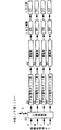
(3)LED画像記録
次に、図3によりLED画像記録について説明する。図3において、画像処理部からの信号は2値変換部201で2値化され、ビデオ信号カウント部220〜223に送られる。ビデオ信号カウント部220〜223では各色画像毎に、LEDの発光素子総数をカウントすることができる。
【0055】
その後2値化された画像信号は、遅延部202、203、204、205において紙先端センサ347とそれぞれの画像形成位置との距離に応じて遅延され、LED駆動206、207、208、209に送られる。LED駆動206、207、208、209はLED210、211、212、213を駆動するための信号を生成する。
【0056】
(4)カラーモードによる色帯(帯形状トナー像)形成動作
次に、本発明の特徴部分である画像形成モードに応じて、カウント手段を実行し、カウント値が所定の枚数を越えた場合に像担持体上に帯形状トナー像を形成し、搬送紙以外へ転写する方法について詳細に説明する。
【0057】
図5に本実施例のカラー画像形成装置の操作部Cを示す。9001はタッチパネルディスプレイであり、通常はコピー枚数、選択用紙サイズ、倍率、コピー濃度が表示されている。9002はリセットキーであり、コピーモードを標準モードに戻す。9003はスタートキーであり、コピー動作を開始する。9004はストップキーであり、コピー動作を中断する。9005はクリアキーであり、コピーモードを標準モードに戻す。9006はテンキーであり、コピー枚数を設定する。
【0058】
9007は画像形成モード選択手段としてのカラーモード選択キーであり、原稿に関係なく黒単色出力するBlaCKキーと、原稿に関係なくカラー出力するColorキーと、原稿がカラーであるか白黒であるかを自動的に判別して、カラーの場合はカラーで出力し、白黒の場合は白黒で出力するACSキーとがありいずれか一つのキーが点灯している。
【0059】
BlaCKキーが選択された場合、Y画像形成部317、M画像形成部318、C画像形成部319では用紙を搬送するために感光ドラムのみが回転し、K画像形成部320の処理により黒の画像形成を行い黒単色画像が形成される。
【0060】
Colorキーが選択された場合、Y画像形成部317、M画像形成部318、C画像形成部319、K画像形成部320の全てにおいて画像形成のための処理が行われ、フルカラー画像が形成される。
【0061】
ACSキーが選択された場合、カラーリーダー部Bの読み取った原稿が黒単色か否かによって、上記の黒単色画像形成とフルカラー画像形成のいずれかが行われる。
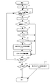
【0062】
以下、図6を用いて詳細に説明する。ユーザーがカラーモードの設定を行ってスタートキー9003でプリントジョブを開始すると、ステップS1でジョブ中の給紙枚数fを0にする。ジョブ中の給紙枚数fは、色帯形成動作をジョブ途中で行うか後回転時に行うかを判断するために用いる。ステップS2で用紙がレジストローラの位置に搬送されたか否かを判断し、YESであれば、ステップS3で、ジョブ中の給紙枚数fを「1」カウントアップする。
【0063】
次にステップS4で画像形成が黒単色かどうかを判断し、YESの黒単色の場合にはステップS5で黒単色画像形成枚数nを「1」カウントアップする。黒単色画像形成枚数nは、Y画像形成部317、M画像形成部318、C画像形成部319で画像形成が行われなかった枚数であり、これらY、M、C画像形成部(第1の画像形成部)で色帯形成動作を行うかどうかの判断に用いる。そして、ステップS6で黒単色画像形成枚数nが所定値500枚を越えたかを判断し、YESであれば、ステップS7でジョブ中の給紙枚数fが所定値50枚を越えているかを判断し、YESの場合には、レジストローラ位置に用紙を止めたままステップS8で黒以外のY、M、C画像形成部において色帯形成動作を実行する。この動作は、Y、M、C画像形成部それぞれで幅2mmの帯形状トナー像を感光ドラム上に形成し、これを転写ベルトに転写し、転写ベルト333上の色帯画像を転写ベルトクリーナー380で回収する。即ち、K画像形成部(第2の画像形成部)以外のY、M、C画像形成部(第1の画像形成部)の感光ドラムに帯形状トナーを形成させ、該帯形状トナーを転写ベルト333に転写させた後に感光ドラム上に残留する外添剤を帯電器に供給する。そして、この動作終了時に黒単色画像形成枚数nを0にクリアし、ステップS9において所定のタイミングでレジストローラから用紙を給紙し、ジョブを継続する。
【0064】
給紙枚数が50枚未満のジョブの色帯形成動作は、ステップS6のNOの場合で黒単色画像形成枚数nが所定値500枚を越え、ステップS7のNOの場合でジョブ中の給紙枚数fが所定値50枚を越えていないため、ステップS9でレジストローラから用紙を給紙して画像形成を行う。ステップS10において最終紙かと判断し、YESの場合は、ステップS11で黒単色画像形成枚数nが所定値500枚を越えているかを判断し、YESであれば、ステップ12において後回転時に前述した色帯形成動作を実行する。
実施例2.
図7を用いて、実施例2について詳細に説明する。ユーザーがタッチパネルディスプレイ9001から用紙サイズの選択を行ってスタートキー9003でプリントジョブを開始すると、ステップS1でジョブ中の給紙枚数fを0にする。ジョブ中の給紙枚数fは、色帯形成動作をジョブ途中で行うか後回転時に行うかを判断するために用いる。ステップS2で用紙がレジストローラの位置に搬送されたかを判断し、YESと検知したら、ステップS3で、ジョブ中の給紙枚数fを「1」カウントアップする。
【0065】
次にステップS4で搬送用紙の主走査方向の長さが所定値210mm以下かどうかを判断し、210mm以下のYESの場合にはステップS5で小サイズ画像形成枚数sを「1」カウントアップする。小サイズ画像形成枚数sは、Y画像形成部317、M画像形成部318、C画像形成部319、K画像形成部320で感光ドラムの両端に画像形成が行われなかった枚数であり、これらY、M、C、K画像形成部で色帯形成動作を行うかどうかの判断に用いる。
【0066】
そして、ステップS6で小サイズ画像形成枚数sが所定値500枚を越えたかを判断し、YESであれば、ステップS7でジョブ中の給紙枚数fが所定値50枚を越えたかを判断し、YESの場合には、レジストローラ位置に用紙を止めたままステップS8でY、M、C、K画像形成部において色帯形成動作を実行する。この動作は、Y、M、C、K画像形成部それぞれで幅2mmの帯形状トナー像を感光ドラム上に形成しこれを転写ベルトに転写し、転写ベルト上の色帯画像を転写ベルトクリーナー380で回収する。そして、この動作終了時に小サイズ画像形成枚数sを0にクリアし、ステップS9において所定のタイミングでレジストローラから用紙を給紙し、ジョブを継続する。
【0067】
給紙枚数が50枚未満のジョブの色帯形成動作は、ステップS6でNOであれば、小サイズ画像形成枚数sが所定値500枚を越え、ステップS7でNOであれば、ジョブ中の給紙枚数fが所定値50枚を越えていないため、ステップS9でレジストローラから用紙を給紙して画像形成を行う。ステップS10において最終紙かと判断し、YESであれば、ステップS11で小サイズ画像形成枚数sが所定値500枚を越えているかを判断し、YESであれば、ステップ12において後回転時に前述した色帯形成動作を実行する。
【0068】
【発明の効果】
以上説明したように、本発明によれば、画像形成が行われない像担持体に対し、又は幅サイズが所定サイズ以下である記録紙を所定枚数通紙した場合の像担持体に対し、帯状のトナー像を形成し、転写後に像担持体上に残ったトナー外添剤を帯電器内に供給、攪拌し、外添剤が付着したキャリアで像担持体上を削ることによってキャリア漏れの原因となる像担持体上の紙紛を取り除き、画像形成時に安定した画像品質を保つことができるという効果がある。
【図面の簡単な説明】
【図1】 本発明の実施例におけるカラー画像形成装置の構成図。
【図2】 ディジタル画像処理部の構成を示すブロック図。
【図3】 LED駆動部の構成を示すブロック図。
【図4】 帯電器の構成を示す概略図。
【図5】 操作部の構成を示す図。
【図6】 カラーモードによる色帯形成を説明するフローチャート。
【図7】 選択用紙サイズによる色帯形成を説明するフローチャート。
【符号の説明】
A・・カラープリンタ部
B・・カラーリーダ部
C・・操作部
322,325,328,331・・画像形成部(Y・M・C・K)
333・・転写ベルト
334・・定着器[0001]
BACKGROUND OF THE INVENTION
The present invention relates to a color image forming apparatus for forming a color image by forming an electrostatic latent image on an image carrier such as a photosensitive drum and developing and transferring the electrostatic latent image for each color. The present invention relates to a color image forming apparatus having no dedicated cleaning device around the image carrier.
[0002]
[Prior art]
In a color image forming apparatus called a color copying machine or a color printer, an electrophotographic method is known. In the image forming process, first, the surface of the photosensitive drum is uniformly charged by a charging device, and a laser or An electrostatic latent image is formed by the LED. Next, the electrostatic latent image is developed with toner, and the toner image is transferred to a recording material such as paper for each of the colors magenta, cyan, yellow, and black, and the toner image superimposed on the recording material is heated. Thus, a color image is formed by fixing the recording material to the recording material. In this color image forming process, the toner remaining on the photosensitive drum after the transfer is removed by a cleaning device.
[0003]
Incidentally, in recent years, there has been a demand for cost reduction and size reduction of the apparatus, and so-called cleaner-less apparatuses that do not have a cleaning apparatus around an image carrier such as a photosensitive drum have been proposed.
[0004]
In such a cleaner-less apparatus, a contact charging device arranged around the photosensitive drum plays a role of charging the photosensitive drum and removing residual toner on the photosensitive drum.
[0005]
For example, in a color image forming apparatus having a photosensitive drum for each of yellow, magenta, cyan, and black, when printing a black single-color image, the black photosensitive drum is placed by a contact-type charging device disposed around the black photosensitive drum. The charging operation of the contact type charging device which is charged and arranged around the other color photosensitive drums is not performed. On the other hand, when forming a full-color image, the photosensitive drums of all colors are charged by a contact-type charging device arranged around each photosensitive drum.
[0006]
As a method of removing the residual toner on the photosensitive drum of the contact type charging device, the contact type charging device temporarily takes in a small amount of toner remaining on the photosensitive drum after transfer, changes the electrostatic characteristics, and again the photosensitive member. A method is used in which the toner is returned to the drum, and then the developing device collects and reuses the toner. By this method, control is performed such that the residual toner on the surface of the photosensitive drum is collected for a certain period of time during a print job or during post-rotation at the end of the print job.
[0007]
Furthermore, the amount of untransferred toner increases during continuous printing of high-density images, and the process of returning the toner once captured onto the photosensitive drum cannot catch up with the process of capturing the residual toner into the charging device. The residual toner collection time is determined in accordance with the image density and the number of images to be formed, and control for collecting the residual toner is performed for that time.
[0008]
[Problems to be solved by the invention]
However, in the above-described color image forming apparatus, when the black monochromatic image print ratio is extremely high compared to a full color image, a ferrite carrier that forms a dielectric brush in a charging device on a color photosensitive drum that does not form an image. Leaks and causes drum scratches, and this drum scratch causes a noise image to appear during image formation. This is because the weakly magnetic carrier at a position away from the tip of the dielectric brush formed by the carrier in the charging device, that is, the sleeve having a magnetic field, is formed on the photosensitive drum due to paper dust on the surface of the photosensitive drum. Because it is attracted.
[0009]
Usually, when a toner image is formed on a photosensitive drum at the time of image formation, the external additive of the toner remaining on the photosensitive drum after the transfer is taken into the charger and stirred so that the external additive is added to the carrier. Then, the carrier is brought into contact with the photosensitive drum again by the rotation of the sleeve, whereby the surface of the photosensitive drum is scraped to remove the paper dust.
[0010]
The same problem also occurs when paper that is short relative to the length of the photosensitive drum continues to be conveyed, and paper dust scattered in the portion where the paper on both ends of the photosensitive drum does not pass is accumulated, and the charging device carrier leaks. A noise image appears in this portion when image formation is performed due to a scratch on the photosensitive drum.
[0011]
The present invention has been made to solve the above-described conventional problems. The object of the present invention is to form a belt-like toner image on an image carrier on which image formation is not performed, and to perform photosensitivity after transfer. The toner external additive remaining on the drum is fed into the charging device, stirred, and the photosensitive drum is scraped off with the carrier to which the external additive has adhered to remove paper dust on the photosensitive drum that causes carrier leakage, and image It is to maintain stable image quality during formation.
[0012]
[Means for Solving the Problems]
The present invention is characterized by the following configuration.PaintingAn image forming apparatus.
(1) a first image forming unit that forms a toner image containing an external additive, a second image forming unit that forms a toner image of a color different from that of the first image forming unit, and the first and second images A member that contacts both the forming unit and the recording material for transferring the toner images formed by the first and second image forming units to the recording paper, and that displays the color image on the recording paper. An image forming apparatus capable of forming, wherein the first image forming unit includes a first image carrier that carries a toner image, a charger that carries a magnetic carrier on a surface and charges the first image carrier, A first development that develops the latent image formed on the first image carrier after charging with toner and collects the toner that remains on the first image carrier without being transferred during the previous image formation. A second image carrier that carries a toner image; and A latent image formed on the two-image carrier with toner, and a second developer that collects toner remaining on the second image-bearing member without being transferred during the previous image formation. In the image forming apparatus for rotating the first and second image carriers together with the member during the image forming operation,
A counting unit that counts the number of images formed in a mode in which an image is formed on recording paper using only the second image forming unit, and a band shape on the first image carrier each time the count value by the counting unit exceeds a predetermined value Control means for controlling the external additive remaining on the first image carrier after forming the toner and transferring the belt-shaped toner to the member to be supplied to the charger. An image forming apparatus.
(2) The control means interrupts the image forming job to form the belt-shaped toner image when the number of images continuously formed in the mode exceeds a predetermined number smaller than the predetermined value. The image forming apparatus according to (1), wherein if the predetermined number of sheets is not exceeded, the belt-shaped toner image is formed during post-rotation.
(3) a first image forming unit that forms a toner image including an external additive, a second image forming unit that forms a toner image of a color different from that of the first image forming unit, and the first and second images. A member that contacts both the forming unit and the recording material for transferring the toner images formed by the first and second image forming units to the recording paper, and that displays the color image on the recording paper. An image forming apparatus capable of forming, wherein the first image forming unit includes a first image carrier that carries a toner image, a charger that carries a magnetic carrier on a surface and charges the first image carrier, A first development that develops the latent image formed on the first image carrier after charging with toner and collects the toner that remains on the first image carrier without being transferred during the previous image formation. A second image carrier that carries a toner image; and A latent image formed on the two-image carrier with toner, and a second developer that collects toner remaining on the second image-bearing member without being transferred during the previous image formation. In the image forming apparatus for rotating the first and second image carriers together with the member during the image forming operation,
A counting unit that counts the number of continuous images formed in a mode in which an image is formed on recording paper using only the second image forming unit, and a count value by the counting unit exceeds a predetermined value, the first image carrier Control means for controlling the external additive remaining on the first image carrier after the belt-shaped toner is formed and transferred to the member to the charger. An image forming apparatus characterized by the above.
(4)A first image forming unit that forms a toner image including an external additive, a second image forming unit that includes an external additive and forms a toner image having a color different from that of the first image forming unit; A member that contacts both the second image forming unit and a recording material for transferring the toner images formed by the first and second image forming units to the recording paper. An image forming apparatus capable of forming a color image, wherein each of the first and second image forming units carries an image carrier that carries a toner image, and a charger that carries a magnetic carrier on the surface and charges the image carrier. And developing the latent image formed on the image carrier with toner, and collecting the toner remaining on the image carrier without being transferred during the previous image formation. The image carrier of the first and second image forming units is rotated together with the member during the forming operation. In the image forming apparatus in which,
Counting means for counting the number of image forming sheets of recording paper whose size in the width direction of the recording paper is a predetermined size or less, and an image carrier of the first and second image forming units each time the count exceeds a predetermined value The external additive remaining on the image carrier of the first and second image forming portions after the belt-shaped toner is formed on the image forming member and the belt-shaped toner is transferred to the member, respectively. An image forming apparatus comprising: a control unit configured to control supply to a charger of the image forming unit.
(5) When the size of the recording paper in the width direction is equal to or smaller than the predetermined size and the number of images to be continuously formed exceeds a predetermined number smaller than the predetermined value, the control unit interrupts the image forming job. The image forming apparatus according to (3), wherein the belt-shaped toner image is formed, and if the predetermined number of sheets is not exceeded, the belt-shaped toner image is formed during post-rotation.
(6)A first image forming unit that forms a toner image including an external additive, a second image forming unit that includes an external additive and forms a toner image having a color different from that of the first image forming unit; A member that contacts both the second image forming unit and a recording material for transferring the toner images formed by the first and second image forming units to the recording paper. An image forming apparatus capable of forming a color image, wherein each of the first and second image forming units carries an image carrier that carries a toner image, and a charger that carries a magnetic carrier on the surface and charges the image carrier. And developing the latent image formed on the image carrier with toner, and collecting the toner remaining on the image carrier without being transferred during the previous image formation. The image carrier of the first and second image forming units is rotated together with the member during the forming operation. In the image forming apparatus in which,
Counting means for counting the number of images continuously formed on a recording sheet whose width in the width direction is equal to or less than a predetermined size, and the first and second images when the count exceeds a predetermined value An external additive remaining on the image carrier of the first and second image forming units after the belt-shaped toner is formed on the image carrier of the forming unit and the belt-shaped toner is transferred to the member, respectively. An image forming apparatus comprising: a control unit configured to control the first and second image forming units to be supplied to the charger.
[0021]
DETAILED DESCRIPTION OF THE INVENTION
Hereinafter, an embodiment of the present invention will be described with reference to the drawings.
Example 1.
FIG. 1 is a schematic configuration diagram of a color image forming apparatus of this embodiment. This color image forming apparatus is a color image forming apparatus using an electrophotographic process, and is roughly composed of a color reader unit B and a color printer unit A.
[0022]
(1) Configuration of color reader unit B
In FIG. 1, an original platen glass (platen) 301 is horizontally provided above the color reader unit B, and an original feeder (DF) 302 is provided thereon. There is a configuration in which a mirror pressure plate is mounted instead of the
[0023]
In the
[0024]
Further, mirrors 308 and 309 for condensing the reflected light from the
[0025]
Further, the
[0026]
The
[0027]
FIG. 2 is a block diagram showing a detailed configuration of the digital
[0028]
Then, the electric signal (analog image signal) is input to the
[0029]
The RGB signal is subjected to shading correction and black correction by the
[0030]
The input
[0031]
The signal output from the
[0032]
In order to correct the signal and timing generated by the black
[0033]
Here, “LOG” is a log conversion LOG used in mathematics. “CMY” means Cyan, Yellow, Magenta. “UCR” is an abbreviation for Under Color Reduction.
[0034]
The “color space compression & background removal & LOG conversion unit” determines whether the read image signal is within the range that can be reproduced by the printer, and if it is included, the image signal is read as it is. Make corrections so that they can be reproduced by the printer. Then, background removal processing is performed, and RGB signals are converted to CMY signals by LOG conversion.
[0035]
In the UCR & masking & black
[0036]
That is, the signal processed by the scaling
[0037]
The signal processed by the UCR & masking & black
[0038]
The signal processed as described above is converted from an 8-bit multilevel signal to a binary signal by the
[0039]
(2) Configuration of color printer unit A
In FIG. 1, a Y (yellow) image forming unit 317, an M (magenta)
Here, in correspondence with the description of the claims, the K (black) image forming unit 320 is the second image forming unit. At least one of the Y (yellow) image forming unit 317, the M (magenta)
[0040]
The
[0041]
Since the Y image forming unit 317, the M
[0042]
The Y image forming unit 317 is provided with a
In these operations, first, the
[0043]
The charger 321 in this example is a magnetic brush contact charger.(Charger that carries the magnetic carrier on the surface and charges the image carrier)As shown in FIG. 4, a low-
[0044]
Next, a latent image is formed on the surface of the photosensitive drum by the light from the
[0045]
The developing
[0046]
After this transfer, the
[0047]
Next, a procedure for forming an image on recording paper or the like will be described. The recording paper and the like stored in the
[0048]
The leading edge of the recording paper fed to the
[0049]
Thereafter, the recording paper or the like is conveyed by the
[0050]
In the black mode, which is black monochromatic image formation, toner image formation is executed only by the K image forming unit 320, and a black K toner image is formed on the recording paper or the like conveyed by the
[0051]
The recording paper or the like that has passed through the K image forming unit 320 is separated from the
[0052]
The separated recording paper or the like is charged by the
[0053]
In the image forming operation described above, the sheet-to-sheet conveyance interval is controlled so that the gap between the sheets is 40 mm when the black monochrome image is formed, and the gap between the sheets is 125 mm when the full-color image is formed.
[0054]
(3) LED image recording
Next, LED image recording will be described with reference to FIG. In FIG. 3, a signal from the image processing unit is binarized by a
[0055]
Thereafter, the binarized image signal is delayed in accordance with the distance between the paper leading
[0056]
(4) Color band (band-shaped toner image) forming operation in color mode
Next, according to the image forming mode which is a characteristic part of the present invention, the counting unit is executed, and when the count value exceeds a predetermined number, a belt-shaped toner image is formed on the image carrier, and other than the transport paper A method for transferring to the sheet will be described in detail.
[0057]
FIG. 5 shows an operation unit C of the color image forming apparatus of this embodiment.
[0058]
[0059]
When the BlaCK key is selected, in the Y image forming unit 317, the M
[0060]
When the Color key is selected, all of the Y image forming unit 317, the M
[0061]
When the ACS key is selected, either the black monochromatic image formation or the full color image formation described above is performed depending on whether or not the original read by the color reader unit B is black monochromatic.
[0062]
Hereinafter, it demonstrates in detail using FIG. When the user sets the color mode and starts a print job with the
[0063]
Next, in step S4, it is determined whether or not image formation is a single black color. If YES, the black single color image formation number n is incremented by "1" in step S5. The black monochromatic image forming number n is the number of images on which the Y image forming unit 317, the M
[0064]
The color band forming operation for a job with less than 50 sheets of paper is performed when the number of black monochrome image formations n exceeds a predetermined value of 500 in the case of NO in step S6, and the number of sheets fed in the job in the case of NO in step S7. Since f does not exceed the predetermined value of 50 sheets, a sheet is fed from the registration roller to form an image in step S9. In step S10, it is determined whether the sheet is the final sheet. If YES, it is determined in step S11 whether the number of black monochromatic images formed n exceeds a predetermined value of 500. A band forming operation is executed.
Example 2
Example 2 will be described in detail with reference to FIG. When the user selects a paper size from the
[0065]
Next, in step S4, it is determined whether or not the length of the conveyance sheet in the main scanning direction is equal to or less than a
[0066]
In step S6, it is determined whether the number of small-size image formation sheets s has exceeded a predetermined value of 500 sheets. If YES, it is determined in step S7 whether the number of fed sheets f in the job has exceeded a predetermined value of 50 sheets. If YES, the color band forming operation is executed in the Y, M, C, K image forming unit in step S8 while the sheet is stopped at the registration roller position. In this operation, each of the Y, M, C, and K image forming units forms a belt-shaped toner image having a width of 2 mm on the photosensitive drum, transfers it to the transfer belt, and transfers the color band image on the transfer belt to the
[0067]
If the color band forming operation for a job with fewer than 50 sheets is NO in step S6, the small-size image forming number s exceeds the
[0068]
【The invention's effect】
As explained above, according to the present invention,The paintingA belt-like toner image is formed on an image carrier on which image formation is not performed or on an image carrier when a predetermined number of recording sheets having a width size equal to or smaller than a predetermined size are passed.Image carrierThe remaining toner external additive is supplied into the charger, stirred, and the paper carrier on the image carrier that causes carrier leakage is removed by scraping the image carrier with the carrier to which the external additive has adhered, There is an effect that stable image quality can be maintained during image formation.
[Brief description of the drawings]
FIG. 1 is a configuration diagram of a color image forming apparatus according to an embodiment of the present invention.
FIG. 2 is a block diagram showing a configuration of a digital image processing unit.
FIG. 3 is a block diagram illustrating a configuration of an LED driving unit.
FIG. 4 is a schematic diagram illustrating a configuration of a charger.
FIG. 5 is a diagram illustrating a configuration of an operation unit.
FIG. 6 is a flowchart for explaining color band formation in a color mode.
FIG. 7 is a flowchart illustrating color band formation based on a selected paper size.
[Explanation of symbols]
A. Color printer section
B. Color reader
C ・ ・ Operation part
322, 325, 328, 331 ... Image forming part (Y / M / C / K)
333 ... Transfer belt
334 .. Fixing device
Claims (6)
前記第2画像形成部のみを用いて記録紙に画像形成するモードにおける画像形成枚数をカウントするカウント手段と、前記カウント手段によるカウント値が所定値を超える毎に前記第1像担持体に帯形状トナーを形成させ、該帯形状トナーを前記部材に転写させた後に前記第1像担持体上に残留する外添剤を前記帯電器に供給するように制御する制御手段と、を有することを特徴とした画像形成装置。A counting unit that counts the number of images formed in a mode in which an image is formed on recording paper using only the second image forming unit, and a band shape on the first image carrier each time the count value by the counting unit exceeds a predetermined value Control means for controlling the external additive remaining on the first image carrier after forming the toner and transferring the belt-shaped toner to the member to be supplied to the charger. An image forming apparatus.
前記第2画像形成部のみを用いて記録紙に画像形成するモードにおける連続画像形成枚数をカウントするカウント手段と、前記カウント手段によるカウント値が所定値を超えた場合、前記第1像担持体に帯形状トナーを形成させ、該帯形状トナーを前記部材に転写させた後に前記第1像担持体上に残留する外添剤を前記帯電器に供給するように制御する制御手段と、を有することを特徴とした画像形成装置。A counting unit that counts the number of continuous images formed in a mode in which an image is formed on recording paper using only the second image forming unit, and a count value by the counting unit exceeds a predetermined value, the first image carrier Control means for controlling the external additive remaining on the first image carrier after the belt-shaped toner is formed and transferred to the member to the charger. An image forming apparatus characterized by the above.
前記記録紙の幅方向のサイズが所定サイズ以下である記録紙の画像形成枚数をカウントするカウント手段と、前記カウントが所定値を超える毎に前記第1及び第2の画像形成部Count means for counting the number of image forming sheets of recording paper whose size in the width direction of the recording paper is equal to or smaller than a predetermined size, and the first and second image forming sections each time the count exceeds a predetermined value の像担持体に帯形状トナーを形成させ、該帯形状トナーを前記部材に転写させた後に前記第1及び第2の画像形成部の像担持体上に残留する外添剤をそれぞれ前記第1及び第2の画像形成部の帯電器に供給するように制御する制御手段と、を有することを特徴とした画像形成装置。After the belt-shaped toner is formed on the image carrier and the belt-shaped toner is transferred to the member, the external additive remaining on the image carrier of the first and second image forming units is respectively the first toner. And an image forming apparatus comprising: a control unit configured to perform control so as to be supplied to the charger of the second image forming unit.
前記記録紙の幅方向のサイズが所定サイズ以下である記録紙にて連続して画像形成した枚数をカウントするカウント手段と、前記カウントが所定値を超えた場合に前記第1及び第2の画像形成部の像担持体に帯形状トナーを形成させ、該帯形状トナーを前記部材に転写させた後に前記第1及び第2の画像形成部の像担持体上に残留する外添剤をそれぞれ前記第1及び第2の画像形成部の帯電器に供給するように制御する制御手段と、を有することを特徴とした画像形成装置。Counting means for counting the number of images continuously formed on a recording sheet whose width in the width direction is equal to or less than a predetermined size, and the first and second images when the count exceeds a predetermined value An external additive remaining on the image carrier of the first and second image forming units after the belt-shaped toner is formed on the image carrier of the forming unit and the belt-shaped toner is transferred to the member, respectively. An image forming apparatus comprising: control means for controlling to supply to the chargers of the first and second image forming units.
Priority Applications (1)
| Application Number | Priority Date | Filing Date | Title |
|---|---|---|---|
| JP2002104884A JP4040346B2 (en) | 2002-04-08 | 2002-04-08 | Image forming apparatus |
Applications Claiming Priority (1)
| Application Number | Priority Date | Filing Date | Title |
|---|---|---|---|
| JP2002104884A JP4040346B2 (en) | 2002-04-08 | 2002-04-08 | Image forming apparatus |
Publications (3)
| Publication Number | Publication Date |
|---|---|
| JP2003295559A JP2003295559A (en) | 2003-10-15 |
| JP2003295559A5 JP2003295559A5 (en) | 2005-03-03 |
| JP4040346B2 true JP4040346B2 (en) | 2008-01-30 |
Family
ID=29243037
Family Applications (1)
| Application Number | Title | Priority Date | Filing Date |
|---|---|---|---|
| JP2002104884A Expired - Fee Related JP4040346B2 (en) | 2002-04-08 | 2002-04-08 | Image forming apparatus |
Country Status (1)
| Country | Link |
|---|---|
| JP (1) | JP4040346B2 (en) |
Families Citing this family (1)
| Publication number | Priority date | Publication date | Assignee | Title |
|---|---|---|---|---|
| US7228088B2 (en) * | 2005-01-21 | 2007-06-05 | Kabushiki Kaisha Toshiba | Color image forming apparatus and color image forming method |
-
2002
- 2002-04-08 JP JP2002104884A patent/JP4040346B2/en not_active Expired - Fee Related
Also Published As
| Publication number | Publication date |
|---|---|
| JP2003295559A (en) | 2003-10-15 |
Similar Documents
| Publication | Publication Date | Title |
|---|---|---|
| JP3907155B2 (en) | Image data correction apparatus, image reading apparatus, and image forming apparatus | |
| JP4992315B2 (en) | Charging device and image forming apparatus using the same | |
| JP2006267682A (en) | Image forming apparatus | |
| JP4798854B2 (en) | Image forming apparatus and residual toner removing method in image forming apparatus | |
| JP4040346B2 (en) | Image forming apparatus | |
| US6256462B1 (en) | Image formation apparatus and control method thereof | |
| JP2003162109A (en) | Color image forming device | |
| JP3408214B2 (en) | Image forming device | |
| US6947680B2 (en) | Image forming apparatus | |
| JP3618992B2 (en) | Image forming apparatus | |
| JP3884871B2 (en) | Image forming apparatus and method of controlling image forming apparatus | |
| JP3897464B2 (en) | Image forming apparatus | |
| JP3402980B2 (en) | Image forming device | |
| JP3619022B2 (en) | Color electrophotographic image forming apparatus | |
| JP2001337504A (en) | Image forming device | |
| JP3720443B2 (en) | Image forming apparatus | |
| JP2005215281A (en) | Residual toner collecting method and image forming apparatus | |
| JP2003162182A (en) | Image forming apparatus | |
| JPH09190079A (en) | Image forming device | |
| JP3403013B2 (en) | Image forming device | |
| JPH0460568A (en) | Image forming device | |
| JP2000137387A (en) | Device and method for image forming and copying machine | |
| JP2001242674A (en) | Image forming device | |
| JPH1195571A (en) | Image forming device | |
| JP2004266736A (en) | Image forming apparatus |
Legal Events
| Date | Code | Title | Description |
|---|---|---|---|
| A521 | Written amendment |
Free format text: JAPANESE INTERMEDIATE CODE: A523 Effective date: 20040326 |
|
| A621 | Written request for application examination |
Free format text: JAPANESE INTERMEDIATE CODE: A621 Effective date: 20040326 |
|
| A977 | Report on retrieval |
Free format text: JAPANESE INTERMEDIATE CODE: A971007 Effective date: 20061221 |
|
| A131 | Notification of reasons for refusal |
Free format text: JAPANESE INTERMEDIATE CODE: A131 Effective date: 20061226 |
|
| A521 | Written amendment |
Free format text: JAPANESE INTERMEDIATE CODE: A523 Effective date: 20070222 |
|
| TRDD | Decision of grant or rejection written | ||
| A01 | Written decision to grant a patent or to grant a registration (utility model) |
Free format text: JAPANESE INTERMEDIATE CODE: A01 Effective date: 20071106 |
|
| A61 | First payment of annual fees (during grant procedure) |
Free format text: JAPANESE INTERMEDIATE CODE: A61 Effective date: 20071107 |
|
| FPAY | Renewal fee payment (event date is renewal date of database) |
Free format text: PAYMENT UNTIL: 20101116 Year of fee payment: 3 |
|
| R150 | Certificate of patent or registration of utility model |
Free format text: JAPANESE INTERMEDIATE CODE: R150 |
|
| FPAY | Renewal fee payment (event date is renewal date of database) |
Free format text: PAYMENT UNTIL: 20101116 Year of fee payment: 3 |
|
| FPAY | Renewal fee payment (event date is renewal date of database) |
Free format text: PAYMENT UNTIL: 20111116 Year of fee payment: 4 |
|
| FPAY | Renewal fee payment (event date is renewal date of database) |
Free format text: PAYMENT UNTIL: 20121116 Year of fee payment: 5 |
|
| FPAY | Renewal fee payment (event date is renewal date of database) |
Free format text: PAYMENT UNTIL: 20131116 Year of fee payment: 6 |
|
| LAPS | Cancellation because of no payment of annual fees |