JP4039742B2 - Automatic article dispenser - Google Patents
Automatic article dispenser Download PDFInfo
- Publication number
- JP4039742B2 JP4039742B2 JP18140398A JP18140398A JP4039742B2 JP 4039742 B2 JP4039742 B2 JP 4039742B2 JP 18140398 A JP18140398 A JP 18140398A JP 18140398 A JP18140398 A JP 18140398A JP 4039742 B2 JP4039742 B2 JP 4039742B2
- Authority
- JP
- Japan
- Prior art keywords
- article storage
- article
- outlet
- automatic
- casing
- Prior art date
- Legal status (The legal status is an assumption and is not a legal conclusion. Google has not performed a legal analysis and makes no representation as to the accuracy of the status listed.)
- Expired - Fee Related
Links
Images


Landscapes
- Control Of Vending Devices And Auxiliary Devices For Vending Devices (AREA)
- Vending Machines For Individual Products (AREA)
- Warehouses Or Storage Devices (AREA)
Description
【0001】
【発明の属する技術分野】
本発明は、ボーリング競技場の貸し靴の提供などに供する自動物品供出機に関するものである。
【0002】
一般に、この種の自動物品供出機は、縦長のケーシングの中に倒伏可能な複数の棚板を縦列に配備しており、これらの棚板に貸し靴等の物品を載せて、硬貨の投入に伴い、下の棚板から順に倒伏させることにより、各棚板上の物品をケーシングの下端に設けた取出口へと次々に落下させるようにしている(実公平2‐1655号公報)。
したがって、この自動物品供出機は、極めてシンプルに、コンパクトに形成できて、設置場所の省スペース化が可能である。また、低コストで生産できて、安価に提供でき、しかも、故障が少ない等々の利点があり、未だ高い需要率を維持している。
【0003】
【発明が解決しようとする課題】
しかし、その反面、
▲1▼ 取出口をケーシングの下端に設けなければならないため、物品を取り出す際にはその都度屈まなければならず、取り出し難い。
▲2▼ 下段の棚板ほど出荷頻度が高く、物品を多く補充することとなるが、上段では逆に少なくなって、ほとんど入れ替わらない。
▲3▼ 物品を全てケーシング下端の取出口まで落下させるため、物品によっては損傷するおそれがある。
▲4▼ 背後から物品を補充するためにケーシングの後面を開放させたものでは、物品が貸し靴の場合、上向きにして棚板に載せることで貸し靴の内部に塵埃が入り易い。
▲5▼ 物品を補充するにも、水平の目線の上方又は下方では品物の有無がわかり難い。
▲6▼ 上部、下部の棚板への物品の補充が容易でない。
等々の問題点も有しており、需要者層、年齢層、性別、地域、時間帯等から好まれない場合もある。
本発明は、これらの問題点を解決した新規な自動物品供出機を提供しようとするものである。
【0004】
【課題を解決するための手段】
上記目的達成のため、請求項1の発明は、前面の適所に取出口を配したケーシング内に、一部をその取出口に隣接させて環状移送ラインを設け、該環状移送ラインには、前面と後面を開放させた複数の物品収納筐を一列に配備させて、これらの物品収納筐を自動制御駆動手段により次々に上記取出口へと移動させるよう構成した移送式物品収納装置と、
上記各物品収納筐をそれぞれ上記取出口にて停止保持させるよう上記移送式物品収納装置に装備させたロック装置と、
上記取出口に位置する物品収納筐の背後に配した物品押出装置と、
上記各物品収納筐への外部からの物品補充手段と
を有して成る。
【0005】
請求項2の発明は、請求項1の自動物品供出機にあって、上記取出口を上記ケーシングの前面中間部に配し、その取出口には、上記移送式物品収納装置の動作との関連で自動的に開閉するシャッタを設け、また、上記物品補充手段として、上記ケーシングの背面を開放させて成る。
【0006】
請求項3の発明は、請求項2の自動物品供出機にあって、上記移送式物品収納装置として、前方に面する長円を形成して上下に張り回したチェーン、その他の長円形無端移送体を設け、上記各物品収納筐を前後面開放の角筒状に形成して、これらの物品収納筐をその長円形無端移送体の外周面に一列に配備させ、また、上記自動制御駆動手段として、上記各物品収納筐を上記取出口へと順次に移動させ停止させる電動移送装置と、取出口に来た物品収納筐が空であることを検出して該物品収納筐の取出口での停止を回避させるパス装置とを具有させて成る。
【0007】
請求項4の発明は、請求項1、請求項2又は請求項3の自動物品供出機にあって、上記移送式物品収納装置に上記各物品収納筐を一定姿勢で移動させるガイドレールを装備させて成る。
【0008】
請求項5の発明は、請求項1、請求項2、請求項3又は請求項4の自動物品供出機にあって、上記ロック装置を上記移送式物品収納装置の回転機構部へ回転不能に機械的に係合させる構造として成る。
【0009】
請求項6の発明は、請求項1、請求項2、請求項3、請求項4又は請求項5の自動物品供出機にあって、上記物品押出装置として、パンタグラフ型電動伸縮装置を用いて成る。
【0010】
【発明の実施の形態】
図面は、請求項1乃至請求項6の発明に係る貸し靴用自動物品供出機を示している。
図1乃至図5において、1は、電気的に回動する移送式物品収納装置、2は、該移送式物品収納装置に設けたロック装置、3は、その物品収納装置に設けた物品押出装置である。
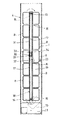
4は、これらの装置を内装し、前面の中間部に取出口5を設け、背面を開放したケーシングである。6は、その取出口に配した電動のシャッタである。
【0011】
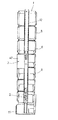
移送式物品収納装置1は、図3に示すように、前方に面して縦長の長円形をなす環状移送ライン7を中間の一部で取出口5に隣接させて設け、該環状移送ラインには、前面と後面を開放させた複数の物品収納筐8を上下に一列に配備させて、それらの物品収納筐を図2、図4に示す自動制御駆動手段9により次々に取出口5へと移動させ停止させるよう構成している。
而して、環状移送ライン7は、図2乃至図5に示すように、制御室10を形成するベース部11から前後一対の支柱12を起立させて、両支柱間の上端部と下端部に回転横軸13,14を軸承させ、両回転横軸の中間部にそれぞれ前後一対のスプロケットホイール15,16を固定し、上下のスプロケットホイール間にそれぞれ移送用チェーン17を掛け渡すことで、前方に面する長円にて上下に張り回した長円形無端移送体18を形成して成り、該長円形無端移送体の外周面に、角筒状で前後面開放の複数の物品収納筐8をそれぞれ連結金物19にて一列に装備させ、更に、両支柱12の内面で左右両側に、それらの物品収納筐8の内壁外面を前後両端部で摺動させて案内する内側のガイドレール77(図2)を付設するとともに、前の支柱12の左右両側に、それらの物品収納筐8の外壁外面を前端部で摺動させて案内する外側のガイドレール78(図4)を付設して、各物品収納筐8を一定姿勢で移動させるようにしている。
また、自動制御駆動手段9は、図2乃至図4に示すように、各物品収納筐8を上記取出口5へと順次に移動させ停止させる電動移送装置20と、その取出口5に来た物品収納筐8に物品が無いことを検出してその停止を回避させるパス装置21とを有して成る。
【0012】
電動移送装置20は、図2乃至図4に示すように、上記制御室10の適所に減速モータ22を配し、該減速モータの出力軸23と上記下の回転横軸14の一端とにスプロケットホイール24,25を設けて駆動用チェーン26を掛け回し、かつ、該駆動用チェーンの中間部分にアイドラ27を装備させて、減速モータ22からの回転力を環状移送ライン7たる長円形無端移送体18(移送用チェーン17)に伝えるようにし、更に、上記制御室10の適所に自動制御器28を配して、該自動制御器により上記減速モータ22したがって長円形無端移送体18の回転を制御し、各物品収納筐8を上記取出口5へと順次に移動させるとともに、各々が定位置に来たことを位置検出器29で検出して電気的に停止させるようにしている(図19)。
この場合の位置検出器29は、リミットスイッチでよく、物品収納筐8が定位置に到来したことを検出すれば足りるが(図2、図19)、無端移送体18(スプロケットホイール15,16、移送用チェーン17)、スプロケットホイール24,25、駆動用チェーン26等の回転機構部の適所に設けた突片でそのリミットスイッチを作動させるようにしてもよい。リミットスイッチに代えてリードスイッチ、近接スイッチ、光電スイッチ等を用い、これらを各物品収納筐8乃至回転機構部に付設した磁石、レフレクタ等により作動させるようにしてもよい。
【0013】
パス装置21は、図2、図3、図9乃至図11に示すように、上記取出口5の部位で上記前後一対の支柱12間に支持バー30を架設して、該支持バーに、スプリング31で出方向に付勢した回動可能な検知レバー32と、該検知レバーで作動される検知スイッチ33とから成る検知器34を装着し、各物品収納筐8の内側壁部に切欠35を設けて、その検知レバー32を該切欠を通じて取出口部位の物品収納筐8内へと遊挿させることで検知器34に当該物品収納筐8内の物品の有無を機械的電気的に検知させ、物品無し(空)の検知に伴い空の当該物品収納筐8を自動的に通過させるよう上記自動制御器28にて上記減速モータ22したがって長円形無端移送体18の回転を制御するようにしている(図19)。ただし、検知器34は、取出口5に位置する物品収納筐8から物品を取り出したことを検出して上記自動制御器28を作動させる物品取出検知器にも兼用している。
なお、検知器34は、光電方式のものでもよい。
【0014】
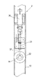
ロック装置2は、図2に示すように、移送式物品収納装置1の回転機構部へ回転不能に機械的に係合させるものであり、下の回転横軸14を物品収納筐8の一つあての移送に1又は2回転させるものとし、図12、図13に示すように、下の回転横軸14の他端にロックホイール36を設け、該ロックホイールの周面の適所にロックホール37を削設し、該ロックホールにスプリングで付勢したロックピン39を挿入させ、該ロックピンを電磁プランジャ38によりそのスプリングに抗して引抜き作動させるようにし、これら電磁プランジャ、ロックピン等を支柱12の適所に装着し、もって、各物品収納筐8の移動に当たり、上記自動制御器28により電磁プランジャ38を作動させることで、ロックピン39をロックホイール36のロックホール37から離脱させて回転機構部を回転させ、また、各物品収納筐8が定位置に来て回転機構部が停止した際には、その電磁プランジャ38をフリーにさせて、ロックピン39をスプリングの弾力でロックホイール36のロックホール37へと挿入させ、回転機構部の回転を阻止して、停止した各物品収納筐8の定位置、とりわけ取出口5に位置する物品収納筐8の定位置を確保させるようにしている(図19)。
なお、ロック装置2については、図14、図15に示すものや図16、図17に示すものを用いてもよい。図14、図15に示すものは、下の回転横軸14にアンモナイト形ホイール40を固定し、該アンモナイト形ホイールに、電磁プランジャ41で作動されるストッパ42を係合離脱自在に対応させたものであり、また、図16、図17に示すものは、下の回転横軸14の上記スプロケットホイール16にロック孔43を穿設し、該ロック孔に、電磁プランジャ44によりリンク機構45を介して出入されるロック棒46を係合離脱自在に対応させたものである。その他にも、上記アンモナイト形ホイール40の代わりに下の回転横軸14のスプロケットホイール16に突子を突設して使用するもの、下の回転横軸14のスプロケットホイール16にドッグクラッチ方式のロック手段を講じたもの、回転機構部のチェーンに回転しないギアを係合離脱自在に対応させたもの等が考えられる。
【0015】
物品押出装置3は、図2、図4、図6乃至図8に示すように、平面形状L形のプレート47にパンタグラフ型電動伸縮装置48を設けて成り、取出口5の後方でかつ物品収納筐8の背後に配して、そのプレート47を以て後部の支柱12の中間部にそのパンタグラフ型電動伸縮装置48を前方へ向けて固定している。
そして、パンタグラフ型電動伸縮装置48は、共通の複数の枢軸49,50,51で枢着した左右一対の平行リンク52の先端に一つの押板53を設けて、前方へ向かう伸縮自在なパンタグラフ54を形成し、該パンタグラフの基端部を各平行リンクにて取付基板55を介して上記プレート47に支持させ、該パンタグラフの基端部を可逆減速モータ57でチェーン機構58を介して開閉動させることにより、当該パンタグラフを伸縮させ、押板53を進退させるようにしており、また、その進出限と後退限を基端部の開閉動に対応させて配した各リミットスイッチ59,60で検出し、上記自動制御器28を働かせて、当該可逆減速モータ57を自動制御するようにしている(図19)。
この場合の可逆減速モータ57は、パンタグラフ54の基端部において、その上方に位置させ、また、チェーン機構58は、その可逆減速モータ57の軸とパンタグラフの基端部の定位置を維持する下の枢軸51とにスプロケットホイール61,62を装着して、両スプロケットホイール間にチェーン63を掛け回し、該チェーンと、パンタグラフ54の基端部の上下動する上の枢軸49とを、連結金物64で機械的に連繋させている。更に、進出限と後退限を検出する各リミットスイッチ59,60は、該上の枢軸49に対応させて配し、上記プレート47の適所に固定している。
【0016】
シャッタ6は、図1、図2、図4、図18に示すように、ケーシング4の前面中途部に設けた取出口5に対応させて配備させており、縦に長い長方形の枠体65を前の支柱12の一側に固定し、該枠体内に板体から成るシャッタ本体66を上昇で開口、下降で閉口するよう昇降可動に装備させ、該シャッタ本体をその枠体65内上部に設けた可逆減速モータ67でチェーン機構68を介して昇降させるようにし、枠体内の中間部にて、そのシャッタ本体66を閉口態勢でロックするシャッタ係止装置69を付設している。
この場合のチェーン機構68は、可逆減速モータ67と枠体65内の中間部に配したスプロケットホイール70,71にチェーン72を掛け回し、その途中にアイドラ73を配することで、可逆減速モータ67の回転に伴いチェーン72を介してシャッタ本体66を昇降させるようにしており、該シャッタ本体の上昇限と下降限をリミットスイッチ79,80で検出して自動制御器28により制御するようにしている(図19)。また、シャッタ係止装置69は、図18に示すように、下降限に位置するシャッタ本体66の上縁を係止爪74で係止し、これを自動制御器28の制御のもと電磁プランジャ75の作動で解除させるようにしている。更に、枠体65内の下端部には、図2に示すように、物品の取り出しを容易にするガイドローラ76を回転自在に装着している。
【0017】
如上の構成であるから、この貸し靴用自動物品供出機は、例えば、硬貨投入装置81(図19)と電気的に連繋させて、一定料金の硬貨の投入で作動させるようにし、移送式物品収納装置1の各物品収納筐8に背後から貸し靴を横向きに挿入(補充)して使用する。押釦操作で電気的に作動させるようにしてもよく、また、これを硬貨投入装置と併用するようにしてもよい。
而して、貸し靴の入った物品収納筐8を予め取出口5に位置させておくが、硬貨投入装置への一定料金の硬貨の投入或いは押釦の操作で、自動制御器28によりシャッタ係止装置69が解除されてシャッタ6が開く。また、物品押出装置3が取出口5に位置する物品収納筐8内に進出して該物品収納筐内の貸し靴を取出口5へと押し出す。この押し出しは途中までであり、後は取出口5から突出している貸し靴を手で引き抜けばよい。引き抜いたところで、貸し靴が無くなったことを検知器34(兼用するパス装置21の検出器)が検出し、自動制御器28により再びシャッタ6が閉じ、シャッタ係止装置69が働く。
これに伴い、自動制御器28により移送式物品収納装置1が作動して、全ての物品収納筐8が環状移送ライン7を一方向に移動し、貸し靴の入った次の物品収納筐8が取出口5に来たところで位置検出器29が働いて定位置に停止する。
この移動と停止は、電動移送装置20とパス装置21とから成る自動制御駆動手段9によって得ており、電動移送装置20により環状移送ライン7たる長円形無端移送体18が回動し、連結金物19を介して各物品収納筐8が連動して、各物品収納筐8が上記取出口5へと順次に移動し、定位置に来て位置検出器29が働いて停止するが、取出口5に来た物品収納筐8内に貸し靴が無いときには、パス装置21によりその停止を回避する。
【0018】
つまり、電動移送装置20は、長円形無端移送体18を形成する前後一対の移送用チェーン17を、制御室10に配した減速モータ22によりスプロケットホイール24,25、駆動用チェーン26等を介して回動させ、その減速モータ22を自動制御器28により制御して、各物品収納筐8を取出口5へと順次に移動させ、各々が定位置に来たことを位置検出器29で検出することにより自動制御器28を働かせてその減速モータ22を停止させ、各物品収納筐8を自動的に定位置に停止させる。
また、パス装置21は、検知器34で取出口5に来た物品収納筐8内に貸し靴が無いことを検出する。この検知器34は、スプリング31で出方向に付勢した検知レバー32を取出口5に来た物品収納筐8内へと切欠35を通じて遊挿させるようにしているから、取出口5に来た物品収納筐8内に貸し靴があればこの貸し靴で検知レバー32が押し動かされて検知スイッチ33が作動し、自動制御器28に各物品収納筐8の定位置停止のための電気的制御をさせる。これとは逆に、取出口5に来た物品収納筐8内に貸し靴が無ければ検知レバーが押し動かされることはなく、検知スイッチ33が切り替わることもないので、取出口5に来た物品収納筐8内に貸し靴が無いことを電気的に検出できて、空の当該物品収納筐8を自動的に通過させるよう自動制御器28に継続作動させ、減速モータ22したがって長円形無端移送体18の回転を持続させ、貸し靴が入った物品収納筐8だけを取出口5に定位置停止させるのである。
【0019】
この定位置停止に伴い、自動制御器28の作動のもとロック装置2が働き、該ロック装置が各物品収納筐8の定位置を確保する。このロック装置2、特に、図2、図5、図12、図13に示すロック装置2の場合は、各物品収納筐8の移動に当たり、自動制御器28により電磁プランジャ38を作動させてロックピン39をロックホイール36のロックホール37から離脱させ、回転機構部を自在に回転させる。また、各物品収納筐8が定位置に来てその回転機構部が停止した際には、電磁プランジャ38をフリーにさせて、ロックピン39をスプリングの弾力でロックホイール36のロックホール37へと挿入させ、回転機構部の回転を阻止して、取出口5に位置する物品収納筐8の定位置を確保させる。
他のロック装置2の場合でも、その機構に相応して作動させることで、回転機構部の回転又は回転阻止を得ればよい。
【0020】
ところで、図18に示すシャッタ係止装置69は、自動制御器28により電磁プランジャ75を作動させて係止爪74を回動させ、シャッタ本体66の上縁から離脱させることで解除させる。再び係合させるときは、電磁プランジャ75及び係止爪74を自重で逆動させる。
また、図2、図4に示すシャッタ6は、自動制御器28により可逆減速モータ67を正転させ、チェーン機構68を介してシャッタ本体66を上昇させることで開扉させる。また、貸し靴の取り出しに伴い、自動制御器28により可逆減速モータ67を逆転させ、チェーン機構68を介してシャッタ本体66を下降させて閉扉させる。
【0021】
図2、図4、図6乃至図8に示す物品押出装置3は、パンタグラフ型電動伸縮装置48において、自動制御器28により可逆減速モータ57を正逆回転させ、チェーン機構58を介してパンタグラフ54の基端部を開閉動させることで、パンタグラフ先端の押板53を進退させる。そして、その進出限と後退限をリミットスイッチ59,60により検出して自動制御器28に所要の制御を得る。
【0022】
なお、以上の説明では、硬貨投入装置に一定料金の硬貨が投入され或いは押釦が操作されると、シャッタ6等の作動が先行し、移送式物品収納装置1等の作動が後行しているが、その先行と後行が逆でもよい。
【0023】
【発明の効果】
本発明によれば、既述構成であるから、次の効果を奏する。
(1) ケーシング内において、物品を収容した複数の物品収納筐が上下に順次に移動するので、ケーシング前面の取出口を中間部等都合のよい任意の高さに配することができ、したがって、物品を取り出す際にその都度屈む必要がなく、取り出し易い。
(2) ケーシング内において、物品を収容した複数の物品収納筐が取出口へと順次に移動するので、収容した物品の出荷頻度が収容場所に関係なく均一となり、均等に入れ替えることができる。
(3) ケーシング内において、物品を収容した複数の物品収納筐を取出口へと順次に移動させるので、物品を落下させる必要がなく、落下による損傷を生じず、落下に伴う騒音も生じない。
(4) ケーシングの後面を開放させても、物品が貸し靴の場合、物品収納筐に横向きに収容させることができ、貸し靴内部に塵埃が入り難い。
(5) ケーシング内において、物品を収容した複数の物品収納筐が上下に順次に移動するので、各物品収納筐内へ物品を補充するにも水平の目線で行え、また、水平の目線で品物の有無を見分けることができて見分け易い。
(6) ケーシング内において、物品を収容した複数の物品収納筐が上下に順次に移動するので、各物品収納筐にはそれぞれ作業員に適合する一定の高さで物品を次々に補充でき、補充作業が容易である。
(7) 全体としてコンパクトに構成でき、専有スペースを少なくできる。
(8) 物品の取り出しの際、自動的にシャッタが開き、物品が押し出されるものとすることができて、取り出しをより容易にすることができる。
【図面の簡単な説明】
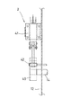
【図1】 本発明の実施の形態に係る正面図である。
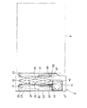
【図2】 同実施の形態に係る截断側面図である。
【図3】 同実施の形態に係る截断正面図である。
【図4】 同実施の形態に係るケーシング除去状態での前面側の斜視図である。
【図5】 同実施の形態に係るケーシング除去状態での背面側の斜視図である。
【図6】 同実施の形態に係る物品押出装置の拡大側面図である。
【図7】 同物品押出装置の動作状態を示す拡大側面図である。
【図8】 同物品押出装置の拡大截断背面図である。
【図9】 同実施の形態に係る検知器の拡大平面図である。
【図10】同検知器の拡大正面図である。
【図11】同検知器の拡大截断側面図である。
【図12】同実施の形態に係るロック装置の拡大正面図である。
【図13】同ロック装置の拡大側面図である。
【図14】他のロック装置の拡大正面図である。
【図15】同ロック装置の拡大側面図である。
【図16】更に他のロック装置の拡大正面図である。
【図17】同ロック装置の拡大側面図である。
【図18】同実施の形態に係るシャッタ係止装置の斜視図である。
【図19】同実施の形態に係る電気回路のブロック図である。
【符号の説明】
1…移送式物品収納装置 2…ロック装置
3…物品押出装置 4…ケーシング
5…取出口 6…シャッタ
7…環状移送ライン 8…物品収納筐
9…自動制御駆動手段 10…制御室
11…ベース部 12…支柱
13,14…回転横軸 15,16…スプロケットホイール
17…移送用チェーン 18…長円形無端移送体
19…連結金物 20…電動移送装置
21…パス装置 22…減速モータ
23…出力軸 24,25…スプロケットホイール
26…駆動用チェーン 27…アイドラ
28…自動制御器 29…位置検出器
30…支持バー 31…スプリング
32…検知レバー 33…検知スイッチ
34…検知器 35…切欠
36…ロックホイール 37…ロックホール
38…電磁プランジャ 39…ロックピン
40…アンモナイト形ホイール 41…電磁プランジャ
42…ストッパ 43…ロック孔
44…電磁プランジャ 45…リンク機構
46…ロック棒 47…プレート
48…パンタグラフ型電動伸縮装置 49,50,51…枢軸
52…平行リンク 53…押板
54…パンタグラフ 55…取付基板
57…可逆減速モータ 58…チェーン機構
59,60…リミットスイッチ 61,62…スプロケットホイール
63…チェーン 64…連結金物
65…枠体 66…シャッタ本体
67…可逆減速モータ 68…チェーン機構
69…シャッタ係止装置 70,71…スプロケットホイール
72…チェーン 73…アイドラ
74…係止爪 75…電磁プランジャ
76…ガイドローラ 77…内側のガイドレール
78…外側のガイドレール 79,80…リミットスイッチ
81…硬貨投入装置[0001]
BACKGROUND OF THE INVENTION
The present invention relates to an automatic article dispenser for use in providing rental shoes for a bowling stadium.
[0002]
In general, this type of automatic article dispenser has a plurality of shelves that can be laid down in a vertically long casing in a series of columns. Along with this, the articles on each shelf board are dropped one after another to the outlet provided at the lower end of the casing by laying down in order from the bottom shelf board (Japanese Utility Model Publication No. 2-1655).
Therefore, the automatic article dispenser can be formed extremely simply and compactly, and the installation space can be saved. In addition, it can be produced at a low cost, can be provided at a low cost, has few advantages such as fewer failures, and still maintains a high demand rate.
[0003]
[Problems to be solved by the invention]
However, on the other hand,
(1) Since the take-out port must be provided at the lower end of the casing, it is necessary to bend each time an article is taken out, which is difficult to take out.
{Circle around (2)} The lower shelves have a higher shipping frequency and more articles will be replenished. However, the upper shelves will be less and will hardly be replaced.
(3) Since all articles are dropped to the outlet at the lower end of the casing, some articles may be damaged.
(4) In the case where the rear surface of the casing is opened in order to replenish the article from behind, when the article is a rental shoe, it is easy to get dust inside the rental shoe by placing it on a shelf board facing upward.
(5) Even when replenishing articles, it is difficult to know the presence or absence of goods above or below the horizontal line of sight.
(6) It is not easy to replenish articles on the upper and lower shelf boards.
Etc., and there are cases where it is not preferred from the consumer group, age group, gender, region, time zone, etc.
The present invention seeks to provide a novel automatic article dispenser that solves these problems.
[0004]
[Means for Solving the Problems]
In order to achieve the above object, an invention according to
A lock device equipped in the transportable article storage device to stop and hold each of the article storage cases at the outlet;
An article extruding device disposed behind the article storage case located at the outlet;
It has an article replenishing means from the outside to each article storage case.
[0005]
The invention according to
[0006]
The invention according to
[0007]
According to a fourth aspect of the present invention, there is provided the automatic article dispensing machine according to the first, second, or third aspect, wherein the transportable article storage device is provided with a guide rail that moves the respective article storage casings in a fixed posture. It consists of
[0008]
According to a fifth aspect of the present invention, there is provided the automatic article dispensing machine according to the first, second, third, or fourth aspect, wherein the lock device is made non-rotatable to the rotation mechanism portion of the transportable article storage device. As a structure to be engaged with each other.
[0009]
The invention according to
[0010]
DETAILED DESCRIPTION OF THE INVENTION
The drawing shows an automatic article dispenser for rental shoes according to the inventions of
1 to 5, 1 is an electrically rotating transferable article storage device, 2 is a lock device provided in the transferable article storage device, and 3 is an article extrusion device provided in the article storage device. It is.
[0011]
As shown in FIG. 3, the transfer-type
Thus, as shown in FIGS. 2 to 5, the
Further, as shown in FIGS. 2 to 4, the automatic control drive means 9 has come to the take-out
[0012]
As shown in FIGS. 2 to 4, the
The
[0013]
As shown in FIGS. 2, 3, 9 to 11, the
The
[0014]
As shown in FIG. 2, the
In addition, about the
[0015]
As shown in FIGS. 2, 4, 6 to 8, the
The pantograph-type electric expansion /
In this case, the reversible
[0016]
As shown in FIGS. 1, 2, 4, and 18, the
In this case, the
[0017]
Since it is configured as above, the automatic article dispenser for rental shoes is electrically connected to, for example, a coin insertion device 81 (FIG. 19), and is operated by inserting coins of a fixed fee, so that a transferable article is provided. Rental shoes are inserted (supplemented) sideways from the back into each
Thus, the
Along with this, the transfer-type
This movement and stop is obtained by automatic control drive means 9 comprising an
[0018]
In other words, the
Further, the
[0019]
With this fixed position stop, the
Even in the case of another
[0020]
Incidentally, the
The
[0021]
The
[0022]
In the above description, when a fixed amount of coins is inserted into the coin insertion device or the push button is operated, the operation of the
[0023]
【The invention's effect】
According to the present invention, since it is the above-described configuration, the following effects are obtained.
(1) In the casing, a plurality of article storage casings containing articles move up and down sequentially, so that the outlet on the front surface of the casing can be arranged at any convenient height such as an intermediate portion, and therefore There is no need to bend each time the article is taken out, and it is easy to take it out.
(2) In the casing, the plurality of article storage casings containing articles are sequentially moved to the outlet, so that the shipping frequency of the contained articles is uniform regardless of the storage location, and can be replaced evenly.
(3) Since a plurality of article storage cases containing articles are sequentially moved to the outlet in the casing, there is no need to drop the articles, no damage is caused by dropping, and no noise is caused by dropping.
(4) Even if the rear surface of the casing is opened, if the article is a rental shoe, it can be stored sideways in the article storage case, and it is difficult for dust to enter the rental shoe.
(5) Since a plurality of article storage cabinets containing articles move up and down sequentially in the casing, it is possible to replenish articles in each article storage cabinet with a horizontal line of sight, and items with a horizontal line of sight. It is easy to tell if there is any.
(6) Since a plurality of article storage cases containing articles move in the casing one after another in the casing, each article storage case can be replenished one after another at a certain height suitable for the worker. Work is easy.
(7) As a whole, it can be configured compactly, and the exclusive space can be reduced.
(8) When the article is taken out, the shutter is automatically opened and the article can be pushed out, so that the taking out can be made easier.
[Brief description of the drawings]
FIG. 1 is a front view according to an embodiment of the present invention.
FIG. 2 is a cutaway side view according to the same embodiment.
FIG. 3 is a cut front view according to the same embodiment;
FIG. 4 is a perspective view of the front side in the casing removal state according to the same embodiment.
FIG. 5 is a perspective view of the back side in the casing removal state according to the same embodiment.
FIG. 6 is an enlarged side view of the article extrusion apparatus according to the embodiment.
FIG. 7 is an enlarged side view showing an operating state of the article extruding apparatus.
FIG. 8 is an enlarged cut rear view of the article extruding apparatus.
FIG. 9 is an enlarged plan view of the detector according to the same embodiment.
FIG. 10 is an enlarged front view of the detector.
FIG. 11 is an enlarged cut-away side view of the same detector.
FIG. 12 is an enlarged front view of the locking device according to the embodiment.
FIG. 13 is an enlarged side view of the locking device.
FIG. 14 is an enlarged front view of another locking device.
FIG. 15 is an enlarged side view of the locking device.
FIG. 16 is an enlarged front view of still another locking device.
FIG. 17 is an enlarged side view of the locking device.
FIG. 18 is a perspective view of the shutter locking device according to the embodiment.
FIG. 19 is a block diagram of an electric circuit according to the embodiment.
[Explanation of symbols]
DESCRIPTION OF
11 ...
13, 14 ... Rotating
17 ...
19 ...
21… Passing
23 ...
26 ...
28 ...
30 ...
32 ...
34 ...
36…
38…
40 ...
42 ...
44 ...
46 ...
48 ... Pantograph type electric
52 ...
54 ...
57 ...
59, 60 ...
63 ...
65 ...
67 ...
69 ... Shutter locking
72 ...
74 ... Locking
76…
78…
81 ... Coin insertion device
Claims (6)
上記各物品収納筐をそれぞれ上記取出口にて停止保持させるよう上記移送式物品収納装置に装備させたロック装置と、
上記取出口に位置する物品収納筐の背後に配した物品押出装置と、
上記各物品収納筐への外部からの物品補充手段と
を有して成る自動物品供出機。An annular transfer line is provided in a casing having an outlet at an appropriate position on the front side, and a part of the casing is adjacent to the outlet, and a plurality of article storage cabinets having a front surface and a rear surface opened are arranged in a row. A transportable article storage apparatus configured to move these article storage cases to the above-mentioned outlets one after another by automatic control drive means,
A lock device equipped in the transportable article storage device to stop and hold each of the article storage cases at the outlet;
An article extruding device disposed behind the article storage case located at the outlet;
An automatic article dispenser comprising an article replenishing means from the outside to each article storage case.
Priority Applications (1)
| Application Number | Priority Date | Filing Date | Title |
|---|---|---|---|
| JP18140398A JP4039742B2 (en) | 1998-06-11 | 1998-06-11 | Automatic article dispenser |
Applications Claiming Priority (1)
| Application Number | Priority Date | Filing Date | Title |
|---|---|---|---|
| JP18140398A JP4039742B2 (en) | 1998-06-11 | 1998-06-11 | Automatic article dispenser |
Publications (2)
| Publication Number | Publication Date |
|---|---|
| JP2000003473A JP2000003473A (en) | 2000-01-07 |
| JP4039742B2 true JP4039742B2 (en) | 2008-01-30 |
Family
ID=16100155
Family Applications (1)
| Application Number | Title | Priority Date | Filing Date |
|---|---|---|---|
| JP18140398A Expired - Fee Related JP4039742B2 (en) | 1998-06-11 | 1998-06-11 | Automatic article dispenser |
Country Status (1)
| Country | Link |
|---|---|
| JP (1) | JP4039742B2 (en) |
Cited By (1)
| Publication number | Priority date | Publication date | Assignee | Title |
|---|---|---|---|---|
| CN109859331A (en) * | 2019-03-06 | 2019-06-07 | 深圳市雷凌广通技术研发有限公司 | A kind of dust-protection type ticket-selling device for urban transportation based on block chain technology |
Families Citing this family (3)
| Publication number | Priority date | Publication date | Assignee | Title |
|---|---|---|---|---|
| KR200486558Y1 (en) * | 2017-02-21 | 2018-06-05 | 나정환 | Automatic storing device |
| CN109353733B (en) * | 2018-10-15 | 2024-03-12 | 潘秀兰 | Rotary disc type article rack |
| CN114468558A (en) * | 2022-01-07 | 2022-05-13 | 安徽继远软件有限公司 | Intelligent seal workbench based on Internet of things |
-
1998
- 1998-06-11 JP JP18140398A patent/JP4039742B2/en not_active Expired - Fee Related
Cited By (1)
| Publication number | Priority date | Publication date | Assignee | Title |
|---|---|---|---|---|
| CN109859331A (en) * | 2019-03-06 | 2019-06-07 | 深圳市雷凌广通技术研发有限公司 | A kind of dust-protection type ticket-selling device for urban transportation based on block chain technology |
Also Published As
| Publication number | Publication date |
|---|---|
| JP2000003473A (en) | 2000-01-07 |
Similar Documents
| Publication | Publication Date | Title |
|---|---|---|
| CN106485834B (en) | Automatic vending machine | |
| US5131449A (en) | Folding door storage system for a closet | |
| EP2006812B1 (en) | Apparatus for storing and selectively retrieving articles, and vending machine including such apparatus | |
| JP4039742B2 (en) | Automatic article dispenser | |
| JP3952579B2 (en) | vending machine | |
| CN110503769B (en) | Vending machine | |
| US20040026446A1 (en) | Small-sized vending machine | |
| KR102541531B1 (en) | Take-out mechanism of product vending machine | |
| EP1565894B1 (en) | Packaged product vending machine | |
| US4209111A (en) | Shelf locking apparatus | |
| CN108074343B (en) | Automatic vending machine | |
| US4046440A (en) | Vendor with door and shelf interlock | |
| JPH0519111Y2 (en) | ||
| CN208985276U (en) | The intelligent vending machine for having double warehousing cabinets | |
| CN111588228A (en) | Goods show sales equipment and storing frame thereof | |
| JPH09259342A (en) | Horizontal array housing type automatic vending machine | |
| JPH067438Y2 (en) | vending machine | |
| KR102477640B1 (en) | A module apparatus is able to install vending machine in inside of a wall | |
| JP2002150413A (en) | Vending machine | |
| JP2000259941A (en) | Merchandise housing and ejecting device for automatic vending machine | |
| JP4297989B2 (en) | Product take-out device | |
| CN110269435B (en) | Sock storage device | |
| JP2612048B2 (en) | Product unloading device for vending machines | |
| JP2501253Y2 (en) | Rice ball vending machine | |
| JPH0342231Y2 (en) |
Legal Events
| Date | Code | Title | Description |
|---|---|---|---|
| A621 | Written request for application examination |
Free format text: JAPANESE INTERMEDIATE CODE: A621 Effective date: 20050314 |
|
| RD02 | Notification of acceptance of power of attorney |
Free format text: JAPANESE INTERMEDIATE CODE: A7422 Effective date: 20061204 |
|
| A977 | Report on retrieval |
Free format text: JAPANESE INTERMEDIATE CODE: A971007 Effective date: 20071010 |
|
| TRDD | Decision of grant or rejection written | ||
| A01 | Written decision to grant a patent or to grant a registration (utility model) |
Free format text: JAPANESE INTERMEDIATE CODE: A01 Effective date: 20071023 |
|
| A61 | First payment of annual fees (during grant procedure) |
Free format text: JAPANESE INTERMEDIATE CODE: A61 Effective date: 20071106 |
|
| FPAY | Renewal fee payment (event date is renewal date of database) |
Free format text: PAYMENT UNTIL: 20101116 Year of fee payment: 3 |
|
| R150 | Certificate of patent or registration of utility model |
Free format text: JAPANESE INTERMEDIATE CODE: R150 |
|
| FPAY | Renewal fee payment (event date is renewal date of database) |
Free format text: PAYMENT UNTIL: 20101116 Year of fee payment: 3 |
|
| FPAY | Renewal fee payment (event date is renewal date of database) |
Free format text: PAYMENT UNTIL: 20111116 Year of fee payment: 4 |
|
| FPAY | Renewal fee payment (event date is renewal date of database) |
Free format text: PAYMENT UNTIL: 20111116 Year of fee payment: 4 |
|
| FPAY | Renewal fee payment (event date is renewal date of database) |
Free format text: PAYMENT UNTIL: 20121116 Year of fee payment: 5 |
|
| FPAY | Renewal fee payment (event date is renewal date of database) |
Free format text: PAYMENT UNTIL: 20121116 Year of fee payment: 5 |
|
| FPAY | Renewal fee payment (event date is renewal date of database) |
Free format text: PAYMENT UNTIL: 20131116 Year of fee payment: 6 |
|
| R250 | Receipt of annual fees |
Free format text: JAPANESE INTERMEDIATE CODE: R250 |
|
| R250 | Receipt of annual fees |
Free format text: JAPANESE INTERMEDIATE CODE: R250 |
|
| R250 | Receipt of annual fees |
Free format text: JAPANESE INTERMEDIATE CODE: R250 |
|
| R250 | Receipt of annual fees |
Free format text: JAPANESE INTERMEDIATE CODE: R250 |
|
| LAPS | Cancellation because of no payment of annual fees |