JP4035708B2 - Sound velocity measuring device - Google Patents
Sound velocity measuring device Download PDFInfo
- Publication number
- JP4035708B2 JP4035708B2 JP2002144133A JP2002144133A JP4035708B2 JP 4035708 B2 JP4035708 B2 JP 4035708B2 JP 2002144133 A JP2002144133 A JP 2002144133A JP 2002144133 A JP2002144133 A JP 2002144133A JP 4035708 B2 JP4035708 B2 JP 4035708B2
- Authority
- JP
- Japan
- Prior art keywords
- electrode
- substance
- distance
- comb
- longitudinal wave
- Prior art date
- Legal status (The legal status is an assumption and is not a legal conclusion. Google has not performed a legal analysis and makes no representation as to the accuracy of the status listed.)
- Expired - Fee Related
Links
Images


Description
【0001】
【発明の属する技術分野】
本発明は、物質の一方の界面を介してその物質中に超音波を照射し、物質のもう一方の界面によって反射させた超音波を遅延電気信号として検出することにより、物質中の音速Vを算出する音速測定装置に関する。
【0002】
【従来の技術】
液中の音速を測定するための超音波技術として、厚み振動モードの矩形状圧電トランスデューサが従来広く用いられている。液体中の超音波を検出するには、このような従来型のトランスデューサは、入力用だけでなく出力用電極としても用いられていたことから、入力電気信号と出力電気信号を区別するためにサーキュレータ等を必要とした。従って、このような従来型のトランスデューサは、複雑な回路構成を必要とし、応答性にも問題があった。一方、圧電基板に設けられたすだれ状トランスデューサは、圧電基板の厚さが波長に比べて十分に厚い場合には、圧電基板が液体と接触するときに液体と固体との界面において漏洩波トランスデューサとして機能する。このとき、圧電基板を伝搬する漏洩弾性表面波は速度分散のない唯一のモードしか存在しない。このようにして、従来の漏洩波トランスデューサは、超音波の照射方向を圧電基板に対し直交させることが難しいという問題を有しており、従って、測定精度に問題があるばかりでなく、安定な駆動も困難である。
【0003】
【発明が解決しようとする課題】
本発明の目的は、小型軽量で、デバイス構成が簡単で、低消費電力駆動が可能で、耐環境性にも優れる音速測定装置を提供することにある。
【0004】
【課題を解決するための手段】
請求項1に記載の音速測定装置は、圧電基板と、櫛型電極AおよびBで成る組み合わせ電極と、対向電極と、距離制御手段と、反射板と、信号分析器から成る音速測定装置であって、前記組み合わせ電極は、前記圧電基板の上端面に設けられており、前記対向電極は前記圧電基板の下端面に設けられていて、前記対向電極の下端面には、物質の一方の界面が接触しており、前記反射板は、前記物質の前記一方の界面と対面するもう一方の界面と接触しており、前記距離制御手段は、前記物質の前記一方の界面と前記もう一方の界面との距離Zi (i=1, 2,…, n)を制御し、前記櫛型電極Aと前記対向電極との間に、周波数fの入力電気信号が入力されることにより、前記圧電基板の下端面に垂直な方向の縦波が前記物質中に照射され、前記縦波は、前記反射板によって反射され、前記櫛型電極Bと前記対向電極との間では、反射された縦波が前記距離Ziに応じた遅延電気信号Di (i=1, 2,…, n)として検出されるとともに、前記入力電気信号からの結合信号も検出され、前記信号分析器では、前記遅延電気信号Diと前記結合信号との干渉信号Ri (i=1, 2,…, n)における各振幅と、前記距離Ziとの関係から距離周期ΔZが検出され、前記物質中の音速Vは、前記周波数fの2倍と前記距離周期ΔZとの積から算出される。
【0005】
請求項2に記載の音速測定装置は、前記圧電基板の厚さに対する前記組み合わせ電極の電極周期長の割合が、前記圧電基板中を伝搬する縦波速度に対する前記物質中を伝搬する縦波速度の割合の4倍以下である。
【0006】
請求項3に記載の音速測定装置は、第1圧電基板と、櫛型電極AおよびBで成る第1組み合わせ電極と、第2圧電基板と、櫛型電極AおよびBで成る第2組み合わせ電極と、対向電極と、距離制御手段と、反射板と、信号分析器から成る音速測定装置であって、前記第1組み合わせ電極は、前記第1圧電基板の下端面に設けられており、前記第1組み合わせ電極の下端面には、物質の一方の界面が接触しており、前記第2組み合わせ電極は、前記第2圧電基板の上端面に設けられており、前記対向電極は前記第1および第2圧電基板の間に設けられていて、前記反射板は、前記物質の前記一方の界面と対面するもう一方の界面と接触しており、前記距離制御手段は、前記物質の前記一方の界面と前記もう一方の界面との距離Zi (i=1, 2,…, n)を制御し、前記第1組み合わせ電極の前記櫛型電極Aと前記対向電極との間に、周波数fの入力電気信号が入力されることにより、前記第1圧電基板の下端面に垂直な方向の縦波が前記物質中に照射され、前記縦波は、前記反射板によって反射され、前記第2組み合わせ電極の前記櫛型電極Bと前記対向電極との間では、反射された縦波が前記距離Ziに応じた遅延電気信号Di (i=1, 2,…, n)として検出されるとともに、前記入力電気信号からの結合信号も検出され、前記信号分析器では、前記遅延電気信号Diと前記結合信号との干渉信号Ri (i=1, 2,…, n)における各振幅と、前記距離Ziとの関係から距離周期ΔZが検出され、前記物質中の音速Vは、前記周波数fの2倍と前記距離周期ΔZとの積から算出される。
【0007】
請求項4に記載の音速測定装置は、前記第1組み合わせ電極の代わりに第1櫛型電極が設けられ、前記第2組み合わせ電極の代わりに第2櫛型電極が設けられた音速測定装置であって、前記第1櫛型電極と前記対向電極との間に、周波数fの入力電気信号が入力されることにより、前記第1圧電基板の下端面に垂直な方向の縦波が前記物質中に照射され、前記縦波は、前記反射板によって反射され、前記第2櫛型電極と前記対向電極との間では、反射された縦波が前記距離Ziに応じた遅延電気信号Di (i=1, 2,…, n)として検出されるとともに、前記入力電気信号からの結合信号も検出される。
【0008】
請求項5に記載の音速測定装置は、前記物質が液体または細胞質で成る。
【0009】
請求項6に記載の音速測定装置は、前記物質の前記一方の界面と接触する部位に、新たに高分子膜が設けられている。
【0010】
【発明の実施の形態】
本発明の音速測定装置は、2つのタイプに大別される。第1のタイプの音速測定装置は圧電基板と、櫛型電極AおよびBで成る組み合わせ電極と、対向電極と、距離制御手段と、反射板と、信号分析器から成る簡単な構造を有する。組み合わせ電極は、圧電基板の上端面に設けられており、対向電極は圧電基板の下端面に設けられている。対向電極の下端面には、物質の一方の界面が接触しており、その一方の界面と対面するもう一方の界面と接触する位置に反射板が設けられている。物質の一方の界面ともう一方の界面との距離Zi (i=1, 2,…, n) は、距離制御手段によって制御される。
【0011】
もしも、櫛型電極Aと対向電極との間に周波数fの入力電気信号が入力されると、圧電基板の下端面に垂直な方向の縦波が物質中に照射される。この縦波は反射板によって反射され、反射された縦波は、櫛型電極Bと対向電極との間で、距離Ziに応じた遅延電気信号Di (i=1, 2,…, n)として検出される。一方、櫛型電極Bと対向電極との間では、入力電気信号からの結合信号も検出される。このようにして、遅延電気信号Diと結合信号との干渉信号Ri (i=1, 2,…, n)が生じる。信号分析器では、干渉信号Riにおける各振幅と、距離Ziとの関係から距離周期ΔZが得られる。物質中の音速Vは、周波数fの2倍と距離周期ΔZとの積から算出される。つまり、物質中の音速Vは、V=2fΔZで表される。
【0012】
第1のタイプの音速測定装置では、圧電基板の厚さに対する組み合わせ電極の電極周期長の割合が、圧電基板中を伝搬する縦波速度に対する物質中を伝搬する縦波速度の割合の4倍以下であるような構造を採用することにより、圧電基板の下端面に対し垂直な方向の縦波を効率よく物質中に照射することが可能となる。
【0013】
第2のタイプの音速測定装置は、第1圧電基板と、櫛型電極AおよびBで成る第1組み合わせ電極と、第2圧電基板と、櫛型電極AおよびBで成る第2組み合わせ電極と、対向電極と、距離制御手段と、反射板と、信号分析器から成る。第1組み合わせ電極は、第1圧電基板の下端面に設けられている。第1組み合わせ電極の下端面には物質の一方の界面が接触している。第2組み合わせ電極は、第2圧電基板の上端面に設けられており、対向電極は第1および第2圧電基板の間に設けられている。
【0014】
もしも、第1組み合わせ電極の櫛型電極Aと対向電極との間に周波数fの入力電気信号が入力されると、第1圧電基板の下端面に垂直な方向の縦波が物質中に照射される。このとき、第1圧電基板の厚さに対する第1組み合わせ電極の電極周期長の割合が、第1圧電基板中を伝搬する縦波速度に対する物質中を伝搬する縦波速度の割合の4倍以下であるような構造を採用することにより、第1圧電基板の下端面に対し垂直な方向の縦波を効率よく物質中に照射することが可能となる。縦波は反射板によって反射され、反射された縦波は、第2組み合わせ電極の櫛型電極Bと対向電極との間で、距離Ziに応じた遅延電気信号Diとして検出される。一方、第2組み合わせ電極の櫛型電極Bと対向電極との間では、入力電気信号からの結合信号も検出される。このようにして、遅延電気信号Diと結合信号との干渉信号Riが生じる。信号分析器では、干渉信号Riにおける各振幅と、距離Ziとの関係から距離周期ΔZが得られる。物質中の音速Vは、V=2fΔZで表される。
【0015】
第2のタイプの音速測定装置では、第1組み合わせ電極の代わりに第1櫛型電極が設けられ、第2組み合わせ電極の代わりに第2櫛型電極が設けられた構造が可能である。もしも、第1櫛型電極と対向電極との間に周波数fの入力電気信号が入力されると、第1圧電基板の下端面に垂直な方向の縦波が物質中に照射される。この縦波は反射板によって反射され、反射された縦波は、第2櫛型電極と対向電極との間で、距離Ziに応じた遅延電気信号Diとして検出される。一方、第2櫛型電極と対向電極との間では、入力電気信号からの結合信号も検出される。このようにして、遅延電気信号Diと結合信号との干渉信号Riが生じる。干渉信号Riにおける各振幅と、距離Ziとの関係から距離周期ΔZが得られる。物質中の音速Vは、V=2fΔZで表される。
【0016】
第1および第2のタイプの音速測定装置では、物質が液体や細胞質で成る構造が可能である。つまり、本発明の音速測定装置によれば、固体だけでなく、液体や細胞質中の音速を求めることが可能である。
【0017】
第1および第2のタイプの音速測定装置では、物質の一方の界面と接触する部位に、シリコンゴム等の高分子膜が設けられた構造が可能である。つまり、第1のタイプでは対向電極の下端面に、第2のタイプでは第1組み合わせ電極の下端面や、第1櫛型電極の下端面に高分子膜が塗布された構造が可能である。このような構造では、高分子膜を塗布しない構造に比べて、縦波をさらに効率よく物質中に照射することが可能となる。
【0018】
【実施例】
図1は本発明の音速測定装置の第1の実施例を示す断面図である。本実施例は圧電基板1、組み合わせ電極2、対向電極3、信号発生器4、信号分析器5、距離制御手段6および反射板7から成る。圧電基板1は厚さ500μmの圧電セラミック薄板で成り、その分極軸の方向が厚さ方向と平行である構造が採用されている。組み合わせ電極2および対向電極3は、ともにアルミニウム薄膜で成り、圧電基板1の上端面および下端面にそれぞれ設けられている。対向電極3の下端面は物質の一方の界面と接触している。反射板7は、物質のもう一方の界面と接触しており、圧電基板1の下端面と平行になるように設置されている。距離制御手段6は物質の一方の界面ともう一方の界面との距離Zi (i=1, 2,…, n)を制御している。このようにして、図1の音速測定装置は、小型軽量でしかも構造が簡単である。
【0019】
図2は組み合わせ電極2の平面図である。組み合わせ電極2は15個の電極対を有し、5mmの電極重複幅(L)と、75μmの電極指幅(W)と、300μmの電極周期長(P)を有する。組み合わせ電極2は櫛型電極2Aおよび2Bから成る。
【0020】
図1の音速測定装置において、周波数fの入力電気信号が信号発生器4から櫛型電極2Aと対向電極3の間に順次に印加されると、物質の一方の界面を介して、その物質中に縦波が照射される。この縦波は圧電基板1の下端面に対し垂直な成分から成る。もしもその物質が水の場合には、水中の縦波速度(VW)はほぼ1,500 m/sである。従って、圧電基板1中の縦波速度(V)は4,500 m/sであることから、V値に対するVW値の割合、つまりVW/Vはほぼ0.333となる。一方、圧電基板1の厚さ(T)に対する組み合わせ電極2の電極周期長(P)の割合、つまりP/Tは300/500、つまり0.6となり、この値は0.333の4倍よりも小さい。このような関係、すなわちP/T < 4Vw/Vという条件のもとでは、圧電基板1の下端面に対し垂直な方向の縦波が効率よく水中に照射される。このような縦波は、たとえば細胞質中にも効率よく照射される。
【0021】
物質の一方の界面を介して照射された縦波は、図1に示されるように、反射板7によって反射される。このとき、物質の一方の界面ともう一方の界面との距離Ziが、距離制御手段6によって徐々に制御されることから、反射された縦波は、櫛型電極2Bと対向電極3との間で距離Ziに応じた遅延電気信号Di (i=1, 2,…, n)として検出される。一方、櫛型電極2Bと対向電極3との間では、入力電気信号からの結合信号も検出される。このとき、遅延電気信号Diと結合信号が干渉し、その結果、干渉信号Ri (i=1, 2,…, n)が生じる。もしも干渉信号Riのそれぞれの振幅と、距離Ziとの関係を図で表せば、距離周期ΔZが得られる。このようにして、物質中の音速Vは、周波数fの2倍と距離周期ΔZとの積から算出される。つまり、物質中の音速Vは、V=2fΔZで表される。
【0022】
図3は、図1の音速測定装置に印加された入力電気信号の周波数fと挿入損失との関係を示す特性図である。但し、物質の一方の界面ともう一方の界面との距離が5cmの場合を示す。図3によれば、周波数fがほぼ4.2 MHzのときに挿入損失が最小となることは明らかである。
【0023】
図4は、図1の音速測定装置における距離Ziと、干渉信号Riの振幅との関係を示す特性図である。但し、入力電気信号の周波数fが4.2 MHzの場合を示す。図4によれば、距離Ziと振幅との間には周期的な関係が存在する。図4における2つの最大振幅間、または2つの最小振幅間の差が距離周期ΔZに相当する。
【0024】
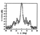
図5は図1の音速測定装置から水中へ照射された縦波の照射角度と、相対振幅との関係を示す特性図である。図5では、縦波の非垂直成分がかなり抑圧されていることがわかる。このことは、組み合わせ電極2を用いれば、ほぼ垂直成分から成る縦波を効率よく水中へ照射することができることを示す。このようにして、ほぼ垂直成分から成る縦波をたとえば皮膚を通して細胞質中に効率よく照射することが可能になる。
【0025】
図6は本発明の音速測定装置の第2の実施例を示す断面図である。本実施例は第1圧電基板8、第1組み合わせ電極9、第2圧電基板10、第2組み合わせ電極11、シリコンゴム12、対向電極3、信号発生器4、信号分析器5、距離制御手段6および反射板7から成る。第2組み合わせ電極11は第2圧電基板10の上端面に、第1組み合わせ電極9は第1圧電基板8の下端面にそれぞれ設けられ、対向電極3は第1圧電基板8と第2圧電基板10の間に設けられている。第1組み合わせ電極9の下端面はシリコンゴム12で覆われており、シリコンゴム12の下端面は物質の一方の界面と接触している。
【0026】
図7は第1組み合わせ電極9および第2組み合わせ電極11の構成図である。第1組み合わせ電極9の電極指の方向は、第2組み合わせ電極11の電極指の方向と直交している。第1組み合わせ電極9は、アルミニウム薄膜で成り、20個の電極対を有し、5mmの電極重複幅(L)と、57μmの電極指幅(W)と、225μmの電極周期長(P)を有する。第2組み合わせ電極11は第1組み合わせ電極9と同様な構造を有する。第1組み合わせ電極9は櫛型電極9Aおよび9Bから成り、第2組み合わせ電極11は櫛型電極11Aおよび11Bから成る。図7では、櫛型電極9Aは信号発生器4に接続され、櫛型電極11Bは信号分析器5に接続されている。
【0027】
図6の音速測定装置において、周波数fの入力電気信号が信号発生器4から櫛型電極9Aと対向電極3の間に順次に印加されると、シリコンゴム12を介して、その物質中に縦波が照射される。この縦波は第1圧電基板8の下端面に対し垂直な成分から成る。もしもその物質が水の場合には、第1圧電基板8の縦波速度(V)に対する水中の縦波速度(VW)の割合、つまりVW/Vは、上述の通りほぼ0.333となる。一方、第1圧電基板8の厚さ(T)に対する第1組み合わせ電極9の電極周期長(P)の割合、つまりP/Tは225/500、つまり0.45となり、この値は0.333の4倍よりも小さい。このような関係、すなわちP/T < 4Vw/Vという条件のもとでは、第1圧電基板8の下端面に対し垂直な方向の縦波が、シリコンゴム12を介して効率よく水中に照射される。さらに、この縦波の指向性は、図1における縦波の指向性よりも鋭い。つまり、P/Tが4Vw/Vよりも小さければ小さいほど、指向性が鋭くなる。
【0028】
シリコンゴム12を介して照射された縦波は、図6に示されるように、反射板7によって反射される。このとき、物質の一方の界面ともう一方の界面との距離Ziが、距離制御手段6によって徐々に制御されることから、反射された縦波は、櫛型電極11Bと対向電極3との間で距離Ziに応じた遅延電気信号Diとして検出される。このとき、反射された縦波の指向性は、先に照射された縦波の指向性よりも鋭い。これは、第1組み合わせ電極9の電極指の方向が、第2組み合わせ電極11の電極指の方向と直交していることに因る。一方、櫛型電極11Bと対向電極3との間では、入力電気信号からの結合信号も検出される。このとき、遅延電気信号Diと結合信号が干渉し、その結果、干渉信号Ri (i=1, 2,…, n)が生じる。もしも干渉信号Riのそれぞれの振幅と、距離Ziとの関係を図で表せば、距離周期ΔZが得られる。このようにして、物質中の音速Vは、周波数fの2倍と距離周期ΔZとの積から算出される。つまり、物質中の音速Vは、V=2fΔZで表される。さらに、図6の音速測定装置を用いれば、図1の場合よりもさらに精密に物質中の音速Vを求めることが可能となる。
【0029】
図8は組み合わせ電極2の電極指交叉領域を示す平面図である。
【0030】
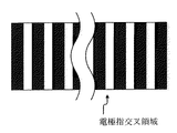
図9は第1組み合わせ電極9の電極指交叉領域を示す平面図である。第1組み合わせ電極9の電極指交叉領域の大きさは、組み合わせ電極2の電極指交叉領域の大きさと同じである。また、櫛型電極9Aの電極指の総面積は、櫛型電極2Aの電極指の総面積と等しい。
【0031】
図8と図9を比較すると、第1組み合わせ電極9と組み合わせ電極2が次のような点で異なることがわかる。第1に電極対の数、第2に電極指幅(W)、そして第3に電極周期長(P)である。第1組み合わせ電極9の電極対の数は組み合わせ電極2の4/3であり、第1組み合わせ電極9の電極周期長(P)は組み合わせ電極2の3/4であり、第1組み合わせ電極9の電極指幅(W)は組み合わせ電極2の3/4である。実際に、組み合わせ電極2を採用した場合に比べて、第1組み合わせ電極9を採用した場合の方が、垂直成分の指向性に優れた縦波を照射できることが確認されている。このことは、入力用電極の電極指の総面積が不変であるならば、その入力用電極の電極対の数が多いほど、物質中に照射される縦波の非垂直成分が抑圧されることを意味する。すなわち、入力用電極の電極指の総面積が不変であるならば、その入力用電極の電極対の数が縦波の指向性に影響を及ぼす。
【0032】
図10は本発明の音速測定装置の第3の実施例を示す断面図である。本実施例は、第1組み合わせ電極9および第2組み合わせ電極11の代わりに第1組み合わせ電極13および第2組み合わせ電極14がそれぞれ用いられていることを除いて、図6と同様な構造を有する。
【0033】
図11は第1組み合わせ電極13および第2組み合わせ電極14の構成図である。第1組み合わせ電極13の電極指の方向は、第2組み合わせ電極14の電極指の方向と直交している。第1組み合わせ電極13は、アルミニウム薄膜で成り、20個の電極対を有し、5mmの電極重複幅(L)と、225μmの電極周期長(P)を有する。第1組み合わせ電極13は櫛型電極13Aおよび13Bから成り、この櫛型電極13A は45μmの電極指幅(WA)を有し、櫛型電極13Bは12μmの電極指幅(WB)を有する。第2組み合わせ電極14は第1組み合わせ電極13と同様な構造を有する。但し、組み合わせ電極14の櫛型電極14Aは12μmの電極指幅(WA)を有し、櫛型電極14Bは45μmの電極指幅(WB)を有する。図10では、櫛型電極13Aは信号発生器4に接続され、櫛型電極14Bは信号分析器5に接続されている。
【0034】
図10の音速測定装置において、周波数fの入力電気信号が信号発生器4から櫛型電極13Aと対向電極3の間に順次に印加されると、シリコンゴム12を介して、その物質中に縦波が照射される。この縦波は第1圧電基板8の下端面に対し垂直な成分から成る。もしもその物質が水の場合には、P/T < 4Vw/Vという条件が満たされることから、第1圧電基板8の下端面に対し垂直な方向の縦波が、シリコンゴム12を介して効率よく水中に照射される。さらに、この縦波の指向性は、図6における縦波の指向性よりも鋭い。つまり、第1組み合わせ電極13におけるWA / WBという条件により、縦波の指向性がさらに鋭くなる。
【0035】
シリコンゴム12を介して照射された縦波は、図10に示されるように反射板7によって反射され、反射された縦波は、櫛型電極14Bと対向電極3との間で距離Ziに応じた遅延電気信号Diとして検出される。このとき、反射された縦波の指向性は、先に照射された縦波の指向性よりも鋭い。これは、第1組み合わせ電極13の電極指の方向が、第2組み合わせ電極14の電極指の方向と直交していることに因る。一方、櫛型電極14Bと対向電極3との間では、入力電気信号からの結合信号も検出される。このとき、遅延電気信号Diと結合信号が干渉し、その結果、干渉信号Riが生じる。もしも干渉信号Riのそれぞれの振幅と、距離Ziとの関係を図で表せば、距離周期ΔZが得られる。このようにして、物質中の音速Vは、周波数fの2倍と距離周期ΔZとの積から算出される。つまり、物質中の音速Vは、V=2fΔZで表される。さらに、図10の音速測定装置を用いれば、図6の場合よりもさらに精密に物質中の音速Vを求めることが可能となる。
【0036】
図12は本発明の音速測定装置の第4の実施例を示す断面図である。本実施例は、第1組み合わせ電極9および第2組み合わせ電極11の代わりに第1櫛型電極15および第2櫛型電極16がそれぞれ用いられていることを除いて、図6と同様な構造を有する。
【0037】
図13は第1櫛型電極15および第2櫛型電極16の構成図である。第1櫛型電極15の電極指の方向は、第2櫛型電極16の電極指の方向と直交している。第1櫛型電極15は40個の電極対を有し、5mmの電極重複幅(L)と、175μmの電極指幅(W)と、225μmの電極周期長(P)を有する。第2櫛型電極16は第1櫛型電極15と同様な構造を有する。
【0038】
図12の音速測定装置において、周波数fの入力電気信号が信号発生器4から第1櫛型電極15と対向電極3の間に順次に印加されると、シリコンゴム12を介して、その物質中に縦波が照射される。この縦波は第1圧電基板8の下端面に対し垂直な成分から成る。もしもその物質が水の場合には、P/T < 4Vw/Vという条件が満たされることから、第1圧電基板8の下端面に対し垂直な方向の縦波が、シリコンゴム12を介して効率よく水中に照射される。
【0039】
シリコンゴム12を介して照射された縦波は、図12に示されるように反射板7によって反射され、反射された縦波は、第2櫛型電極16と対向電極3との間で距離Ziに応じた遅延電気信号Diとして検出される。一方、第2櫛型電極16と対向電極3との間では、入力電気信号Eiからの結合信号Ciも検出される。このとき、遅延電気信号Diと結合信号Ciがそれぞれ干渉し、その結果、各々の干渉信号Riが生じる。もしも干渉信号Riのそれぞれの振幅と、距離Ziとの関係を図で表せば、距離周期ΔZが得られる。このようにして、物質中の音速Vは、周波数fの2倍と距離周期ΔZとの積から算出される。つまり、物質中の音速Vは、V=2fΔZで表される。
【0040】
【発明の効果】
本発明の第1のタイプの音速測定装置は圧電基板と、櫛型電極AおよびBで成る組み合わせ電極と、対向電極と、距離制御手段と、反射板と、信号分析器から成る。組み合わせ電極は、圧電基板の上端面に設けられており、対向電極は圧電基板の下端面に設けられている。対向電極の下端面には、物質の一方の界面が接触しており、その一方の界面と対面するもう一方の界面と接触する位置に反射板が設けられている。物質の一方の界面ともう一方の界面との距離Zi (i=1, 2,…, n) は、距離制御手段によって制御される。櫛型電極Aと対向電極との間に周波数fの入力電気信号が入力されると、圧電基板の下端面に垂直な方向の縦波が物質中に照射される。このとき、圧電基板の厚さに対する組み合わせ電極の電極周期長の割合が、圧電基板中を伝搬する縦波速度に対する物質中を伝搬する縦波速度の割合の4倍以下であるような構造を採用することにより、圧電基板の下端面に対し垂直な方向の縦波を効率よく物質中に照射することが可能となる。縦波は反射板によって反射され、反射された縦波は、櫛型電極Bと対向電極との間で、距離Ziに応じた遅延電気信号Di (i=1, 2,…, n)として検出される。一方、櫛型電極Bと対向電極との間では、入力電気信号からの結合信号も検出される。このようにして、遅延電気信号Diと結合信号との干渉信号Ri (i=1, 2,…, n)が生じる。信号分析器では、干渉信号Riにおける各振幅と、距離Ziとの関係から距離周期ΔZが得られる。物質中の音速Vは、周波数fの2倍と距離周期ΔZとの積から算出される。つまり、物質中の音速Vは、V=2fΔZで表される。
【0041】
本発明の第2のタイプの音速測定装置は第1圧電基板と、櫛型電極AおよびBで成る第1組み合わせ電極と、第2圧電基板と、櫛型電極AおよびBで成る第2組み合わせ電極と、対向電極と、距離制御手段と、反射板と、信号分析器から成る。第1組み合わせ電極は、第1圧電基板の下端面に設けられている。第1組み合わせ電極の下端面には物質の一方の界面が接触している。第2組み合わせ電極は、第2圧電基板の上端面に設けられており、対向電極は第1および第2圧電基板の間に設けられている。第1組み合わせ電極の櫛型電極Aと対向電極との間に周波数fの入力電気信号が入力されると、第1圧電基板の下端面に垂直な方向の縦波が物質中に照射される。このとき、第1圧電基板の厚さに対する第1組み合わせ電極の電極周期長の割合が、第1圧電基板中を伝搬する縦波速度に対する物質中を伝搬する縦波速度の割合の4倍以下であるような構造を採用することにより、第1圧電基板の下端面に対し垂直な方向の縦波を効率よく物質中に照射することが可能となる。縦波は反射板によって反射され、反射された縦波は、第2組み合わせ電極の櫛型電極Bと対向電極との間で、距離Ziに応じた遅延電気信号Diとして検出される。一方、第2組み合わせ電極の櫛型電極Bと対向電極との間では、入力電気信号からの結合信号も検出される。このようにして、遅延電気信号Diと結合信号との干渉信号Riが生じる。信号分析器では、干渉信号Riにおける各振幅と、距離Ziとの関係から距離周期ΔZが得られる。物質中の音速Vは、V=2fΔZで表される。また、第2のタイプの音速測定装置では、第1組み合わせ電極の代わりに第1櫛型電極が設けられ、第2組み合わせ電極の代わりに第2櫛型電極が設けられた構造が可能である。
【0042】
第1および第2のタイプの音速測定装置では、物質が液体や細胞質で成る構造が可能であり、固体だけでなく、液体や細胞質中の音速を求めることが可能である。また、物質の一方の界面と接触する部位に、シリコンゴム等の高分子膜が設けられた構造が可能である。つまり、第1のタイプでは対向電極の下端面に、第2のタイプでは第1組み合わせ電極の下端面や、第1櫛型電極の下端面に高分子膜が塗布された構造が可能である。このような構造では、高分子膜を塗布しない構造に比べて、縦波をさらに効率よく物質中に照射することが可能となる。
【図面の簡単な説明】
【図1】本発明の音速測定装置の第1の実施例を示す断面図。
【図2】組み合わせ電極2の平面図。
【図3】図1の音速測定装置に印加された入力電気信号の周波数fと挿入損失との関係を示す特性図。
【図4】図1の音速測定装置における距離Ziと、干渉信号Riの振幅との関係を示す特性図。
【図5】図1の音速測定装置から水中へ照射された縦波の照射角度と、相対振幅との関係を示す特性図。
【図6】本発明の音速測定装置の第2の実施例を示す断面図。
【図7】第1組み合わせ電極9および第2組み合わせ電極11の構成図。
【図8】組み合わせ電極2の電極指交叉領域を示す平面図。
【図9】第1組み合わせ電極9の電極指交叉領域を示す平面図。
【図10】本発明の音速測定装置の第3の実施例を示す断面図。
【図11】第1組み合わせ電極13および第2組み合わせ電極14の構成図。
【図12】本発明の音速測定装置の第4の実施例を示す断面図。
【図13】第1櫛型電極15および第2櫛型電極16の構成図。
【符号の説明】
1 圧電基板
2 組み合わせ電極
3 対向電極
4 信号発生器
5 信号分析器
6 距離制御手段
7 反射板
8 第1圧電基板
9 第1組み合わせ電極
10 第2圧電基板
11 第2組み合わせ電極
12 シリコンゴム
13 第1組み合わせ電極
14 第2組み合わせ電極
15 第1櫛型電極
16 第2櫛型電極
2A,2B 櫛型電極
9A,9B 櫛型電極
11A,11B 櫛型電極
13A,13B 櫛型電極
14A,14B 櫛型電極[0001]
BACKGROUND OF THE INVENTION
The present invention irradiates an ultrasonic wave into one substance through one interface of the substance, and detects the ultrasonic wave reflected by the other interface of the substance as a delayed electric signal, so that the speed of sound V in the substance is obtained. The present invention relates to a sound speed measuring device to be calculated.
[0002]
[Prior art]
As an ultrasonic technique for measuring the speed of sound in liquid, a rectangular piezoelectric transducer in a thickness vibration mode has been widely used. In order to detect ultrasonic waves in a liquid, such a conventional transducer was used not only as an input but also as an output electrode. Therefore, a circulator is used to distinguish between an input electric signal and an output electric signal. Needed. Therefore, such a conventional transducer requires a complicated circuit configuration and has a problem in response. On the other hand, the interdigital transducer provided on the piezoelectric substrate is a leaky wave transducer at the interface between the liquid and the solid when the piezoelectric substrate comes into contact with the liquid when the thickness of the piezoelectric substrate is sufficiently thick compared to the wavelength. Function. At this time, the leaky surface acoustic wave propagating through the piezoelectric substrate has only one mode without velocity dispersion. Thus, the conventional leaky wave transducer has the problem that it is difficult to make the direction of ultrasonic wave irradiation perpendicular to the piezoelectric substrate. Therefore, not only is there a problem in measurement accuracy, but also stable driving. It is also difficult.
[0003]
[Problems to be solved by the invention]
An object of the present invention is to provide a sound speed measuring device that is small and light, has a simple device configuration, can be driven with low power consumption, and has excellent environmental resistance.
[0004]
[Means for Solving the Problems]
The sound velocity measuring device according to
[0005]
The sonic velocity measuring apparatus according to
[0006]
According to a third aspect of the present invention, there is provided a sound velocity measuring apparatus comprising: a first piezoelectric substrate; a first combination electrode composed of comb electrodes A and B; a second piezoelectric substrate; a second combination electrode composed of comb electrodes A and B; , A sound velocity measuring device comprising a counter electrode, a distance control means, a reflector, and a signal analyzer, wherein the first combination electrode is provided on a lower end surface of the first piezoelectric substrate, One interface of the substance is in contact with the lower end surface of the combination electrode, the second combination electrode is provided on the upper end surface of the second piezoelectric substrate, and the counter electrode is the first and second electrodes. The reflector is provided between the piezoelectric substrates, the reflector is in contact with the other interface facing the one interface of the substance, and the distance control means includes the one interface of the substance and the interface Distance Z with the other interface i (i = 1, 2,..., n) is controlled, and an input electric signal having a frequency f is input between the comb-shaped electrode A of the first combination electrode and the counter electrode. A longitudinal wave in a direction perpendicular to the lower end surface of one piezoelectric substrate is irradiated into the substance, the longitudinal wave is reflected by the reflecting plate, and the comb-shaped electrode B of the second combination electrode and the counter electrode Between the reflected longitudinal waves, the distance Z i Delayed electrical signal D according to i (i = 1, 2,..., n) and a combined signal from the input electrical signal is also detected, and in the signal analyzer, the delayed electrical signal D i And interference signal R of the combined signal i Each amplitude at (i = 1, 2, ..., n) and the distance Z i The distance period ΔZ is detected from the relationship, and the sound velocity V in the substance is calculated from the product of twice the frequency f and the distance period ΔZ.
[0007]
The sound velocity measuring device according to
[0008]
In the sound velocity measuring device according to
[0009]
In the sound velocity measuring apparatus according to the sixth aspect, a polymer film is newly provided at a site in contact with the one interface of the substance.
[0010]
DETAILED DESCRIPTION OF THE INVENTION
The sound velocity measuring device of the present invention is roughly classified into two types. The first type of sound velocity measuring device has a simple structure including a piezoelectric substrate, a combination electrode composed of comb-shaped electrodes A and B, a counter electrode, a distance control means, a reflector, and a signal analyzer. The combination electrode is provided on the upper end surface of the piezoelectric substrate, and the counter electrode is provided on the lower end surface of the piezoelectric substrate. One interface of the substance is in contact with the lower end surface of the counter electrode, and a reflector is provided at a position in contact with the other interface facing the one interface. Distance Z between one interface of the material and the other interface i (i = 1, 2,..., n) is controlled by the distance control means.
[0011]
If an input electric signal having a frequency f is input between the comb electrode A and the counter electrode, a longitudinal wave in a direction perpendicular to the lower end surface of the piezoelectric substrate is irradiated into the material. This longitudinal wave is reflected by the reflecting plate, and the reflected longitudinal wave is a distance Z between the comb-shaped electrode B and the counter electrode. i Delayed electrical signal D according to i It is detected as (i = 1, 2, ..., n). On the other hand, a combined signal from the input electric signal is also detected between the comb electrode B and the counter electrode. In this way, the delayed electrical signal D i Interference signal R i (i = 1, 2, ..., n) occurs. In the signal analyzer, the interference signal R i Each amplitude and distance Z i The distance period ΔZ can be obtained from the relationship. The sound velocity V in the substance is calculated from the product of twice the frequency f and the distance period ΔZ. That is, the sound velocity V in the substance is expressed by V = 2fΔZ.
[0012]
In the first type of sound velocity measuring apparatus, the ratio of the electrode periodic length of the combination electrode to the thickness of the piezoelectric substrate is not more than four times the ratio of the longitudinal wave velocity propagating in the substance to the longitudinal wave velocity propagating in the piezoelectric substrate. By adopting such a structure, it becomes possible to efficiently irradiate a substance with a longitudinal wave in a direction perpendicular to the lower end surface of the piezoelectric substrate.
[0013]
A second type of sound velocity measuring apparatus includes a first piezoelectric substrate, a first combination electrode composed of comb electrodes A and B, a second piezoelectric substrate, a second combination electrode composed of comb electrodes A and B, It consists of a counter electrode, a distance control means, a reflector, and a signal analyzer. The first combination electrode is provided on the lower end surface of the first piezoelectric substrate. One interface of the substance is in contact with the lower end surface of the first combination electrode. The second combination electrode is provided on the upper end surface of the second piezoelectric substrate, and the counter electrode is provided between the first and second piezoelectric substrates.
[0014]
If an input electric signal having a frequency f is input between the comb electrode A of the first combination electrode and the counter electrode, a longitudinal wave in a direction perpendicular to the lower end surface of the first piezoelectric substrate is irradiated into the material. The At this time, the ratio of the electrode periodic length of the first combination electrode to the thickness of the first piezoelectric substrate is less than four times the ratio of the longitudinal wave velocity propagating in the substance to the longitudinal wave velocity propagating in the first piezoelectric substrate. By adopting a certain structure, it becomes possible to efficiently irradiate a substance with a longitudinal wave in a direction perpendicular to the lower end surface of the first piezoelectric substrate. The longitudinal wave is reflected by the reflecting plate, and the reflected longitudinal wave is a distance Z between the comb-shaped electrode B of the second combination electrode and the counter electrode. i Delayed electrical signal D according to i Detected as On the other hand, a combined signal from the input electric signal is also detected between the comb electrode B of the second combination electrode and the counter electrode. In this way, the delayed electrical signal D i Interference signal R i Occurs. In the signal analyzer, the interference signal R i Each amplitude and distance Z i The distance period ΔZ can be obtained from the relationship. The speed of sound V in the substance is represented by V = 2fΔZ.
[0015]
In the second type of sound velocity measuring device, a structure in which a first comb electrode is provided instead of the first combination electrode and a second comb electrode is provided instead of the second combination electrode is possible. If an input electrical signal having a frequency f is input between the first comb electrode and the counter electrode, a longitudinal wave in a direction perpendicular to the lower end surface of the first piezoelectric substrate is irradiated into the material. This longitudinal wave is reflected by the reflecting plate, and the reflected longitudinal wave is a distance Z between the second comb electrode and the counter electrode. i Delayed electrical signal D according to i Detected as On the other hand, a combined signal from the input electric signal is also detected between the second comb electrode and the counter electrode. In this way, the delayed electrical signal D i Interference signal R i Occurs. Interference signal R i Each amplitude and distance Z i The distance period ΔZ can be obtained from the relationship. The speed of sound V in the substance is represented by V = 2fΔZ.
[0016]
In the first and second types of sound velocity measuring apparatuses, a structure in which the substance is made of liquid or cytoplasm is possible. That is, according to the sound velocity measuring apparatus of the present invention, it is possible to obtain the sound velocity not only in a solid but also in a liquid or cytoplasm.
[0017]
The first and second types of sound velocity measuring apparatuses can have a structure in which a polymer film such as silicon rubber is provided at a portion that contacts one interface of a substance. That is, a structure in which the polymer film is applied to the lower end surface of the counter electrode in the first type, the lower end surface of the first combination electrode in the second type, and the lower end surface of the first comb electrode is possible. In such a structure, it becomes possible to irradiate a material with a longitudinal wave more efficiently than a structure in which a polymer film is not applied.
[0018]
【Example】
FIG. 1 is a sectional view showing a first embodiment of a sound velocity measuring apparatus according to the present invention. This embodiment comprises a
[0019]
FIG. 2 is a plan view of the
[0020]
In the sound velocity measuring apparatus of FIG. 1, when an input electrical signal having a frequency f is sequentially applied from the
[0021]
The longitudinal wave irradiated through one interface of the substance is reflected by the reflecting
[0022]
FIG. 3 is a characteristic diagram showing the relationship between the frequency f of the input electrical signal applied to the sound velocity measuring device of FIG. 1 and the insertion loss. However, the case where the distance between one interface of the substance and the other interface is 5 cm is shown. According to FIG. 3, it is clear that the insertion loss is minimized when the frequency f is approximately 4.2 MHz.
[0023]
FIG. 4 shows the distance Z in the sound velocity measuring device of FIG. i And interference signal R i It is a characteristic view which shows the relationship with the amplitude of. However, the case where the frequency f of the input electric signal is 4.2 MHz is shown. According to FIG. 4, the distance Z i There is a periodic relationship between and. The difference between the two maximum amplitudes or the two minimum amplitudes in FIG. 4 corresponds to the distance period ΔZ.
[0024]
FIG. 5 is a characteristic diagram showing the relationship between the irradiation angle of the longitudinal wave irradiated into the water from the sound velocity measuring device of FIG. 1 and the relative amplitude. In FIG. 5, it can be seen that the non-vertical component of the longitudinal wave is considerably suppressed. This indicates that if the
[0025]
FIG. 6 is a sectional view showing a second embodiment of the sound velocity measuring apparatus according to the present invention. In this embodiment, the first
[0026]
FIG. 7 is a configuration diagram of the
[0027]
In the sound velocity measuring device of FIG. 6, when an input electrical signal having a frequency f is sequentially applied between the comb-shaped
[0028]
The longitudinal wave irradiated through the
[0029]
FIG. 8 is a plan view showing an electrode finger crossing region of the
[0030]
FIG. 9 is a plan view showing an electrode finger crossing region of the
[0031]
Comparing FIG. 8 and FIG. 9, it can be seen that the
[0032]
FIG. 10 is a sectional view showing a third embodiment of the sound velocity measuring apparatus according to the present invention. This embodiment has the same structure as that of FIG. 6 except that the
[0033]
FIG. 11 is a configuration diagram of the
[0034]
In the sound velocity measuring apparatus of FIG. 10, when an input electrical signal having a frequency f is sequentially applied between the comb-shaped
[0035]
The longitudinal wave irradiated through the
[0036]
FIG. 12 is a sectional view showing a fourth embodiment of the sound velocity measuring apparatus according to the present invention. This embodiment has the same structure as that of FIG. 6 except that the
[0037]
FIG. 13 is a configuration diagram of the
[0038]
In the sound velocity measuring device of FIG. 12, when an input electrical signal having a frequency f is sequentially applied between the first comb-shaped
[0039]
The longitudinal wave irradiated through the
[0040]
【The invention's effect】
The first type of sound velocity measuring apparatus of the present invention comprises a piezoelectric substrate, a combination electrode composed of comb electrodes A and B, a counter electrode, a distance control means, a reflector, and a signal analyzer. The combination electrode is provided on the upper end surface of the piezoelectric substrate, and the counter electrode is provided on the lower end surface of the piezoelectric substrate. One interface of the substance is in contact with the lower end surface of the counter electrode, and a reflector is provided at a position in contact with the other interface facing the one interface. Distance Z between one interface of the material and the other interface i (i = 1, 2,..., n) is controlled by the distance control means. When an input electric signal having a frequency f is input between the comb electrode A and the counter electrode, a longitudinal wave in a direction perpendicular to the lower end surface of the piezoelectric substrate is irradiated into the substance. At this time, a structure in which the ratio of the electrode periodic length of the combination electrode to the thickness of the piezoelectric substrate is not more than four times the ratio of the longitudinal wave velocity propagating in the substance to the longitudinal wave velocity propagating in the piezoelectric substrate By doing so, it becomes possible to efficiently irradiate a substance with a longitudinal wave in a direction perpendicular to the lower end surface of the piezoelectric substrate. Longitudinal waves are reflected by the reflector, and the reflected longitudinal waves are separated by a distance Z between the comb-shaped electrode B and the counter electrode. i Delayed electrical signal D according to i It is detected as (i = 1, 2, ..., n). On the other hand, a combined signal from the input electric signal is also detected between the comb electrode B and the counter electrode. In this way, the delayed electrical signal D i Interference signal R i (i = 1, 2, ..., n) occurs. In the signal analyzer, the interference signal R i Each amplitude and distance Z i The distance period ΔZ can be obtained from the relationship. The sound velocity V in the substance is calculated from the product of twice the frequency f and the distance period ΔZ. That is, the sound velocity V in the substance is expressed by V = 2fΔZ.
[0041]
The second type of sound velocity measuring apparatus according to the present invention includes a first piezoelectric substrate, a first combination electrode composed of comb electrodes A and B, a second piezoelectric substrate, and a second combination electrode composed of comb electrodes A and B. And a counter electrode, a distance control means, a reflector, and a signal analyzer. The first combination electrode is provided on the lower end surface of the first piezoelectric substrate. One interface of the substance is in contact with the lower end surface of the first combination electrode. The second combination electrode is provided on the upper end surface of the second piezoelectric substrate, and the counter electrode is provided between the first and second piezoelectric substrates. When an input electric signal having a frequency f is input between the comb electrode A of the first combination electrode and the counter electrode, a longitudinal wave in a direction perpendicular to the lower end surface of the first piezoelectric substrate is irradiated into the material. At this time, the ratio of the electrode periodic length of the first combination electrode to the thickness of the first piezoelectric substrate is less than four times the ratio of the longitudinal wave velocity propagating in the substance to the longitudinal wave velocity propagating in the first piezoelectric substrate. By adopting a certain structure, it becomes possible to efficiently irradiate a substance with a longitudinal wave in a direction perpendicular to the lower end surface of the first piezoelectric substrate. The longitudinal wave is reflected by the reflecting plate, and the reflected longitudinal wave is a distance Z between the comb-shaped electrode B of the second combination electrode and the counter electrode. i Delayed electrical signal D according to i Detected as On the other hand, a combined signal from the input electric signal is also detected between the comb electrode B of the second combination electrode and the counter electrode. In this way, the delayed electrical signal D i Interference signal R i Occurs. In the signal analyzer, the interference signal R i Each amplitude and distance Z i The distance period ΔZ can be obtained from the relationship. The speed of sound V in the substance is represented by V = 2fΔZ. Further, the second type of sound velocity measuring device can have a structure in which a first comb electrode is provided instead of the first combination electrode, and a second comb electrode is provided instead of the second combination electrode.
[0042]
In the first and second types of sound velocity measuring apparatuses, a structure in which a substance is made of liquid or cytoplasm is possible, and it is possible to obtain sound velocity not only in solid but also in liquid or cytoplasm. In addition, a structure in which a polymer film such as silicon rubber is provided at a portion in contact with one interface of the substance is possible. That is, a structure in which the polymer film is applied to the lower end surface of the counter electrode in the first type, the lower end surface of the first combination electrode in the second type, and the lower end surface of the first comb electrode is possible. In such a structure, it becomes possible to irradiate a material with a longitudinal wave more efficiently than a structure in which a polymer film is not applied.
[Brief description of the drawings]
FIG. 1 is a sectional view showing a first embodiment of a sound velocity measuring apparatus according to the present invention.
FIG. 2 is a plan view of a
FIG. 3 is a characteristic diagram showing the relationship between the frequency f of the input electrical signal applied to the sound velocity measuring device of FIG. 1 and the insertion loss.
4 is a diagram illustrating a distance Z in the sound velocity measuring device of FIG. i And interference signal R i The characteristic view which shows the relationship with the amplitude of.
5 is a characteristic diagram showing a relationship between an irradiation angle of a longitudinal wave irradiated into water from the sound velocity measuring device of FIG. 1 and a relative amplitude.
FIG. 6 is a sectional view showing a second embodiment of the sound velocity measuring apparatus according to the present invention.
7 is a configuration diagram of a
FIG. 8 is a plan view showing an electrode finger crossing region of the
9 is a plan view showing an electrode finger crossing region of the
FIG. 10 is a sectional view showing a third embodiment of the sound velocity measuring apparatus according to the present invention.
11 is a configuration diagram of a
FIG. 12 is a sectional view showing a fourth embodiment of the sound velocity measuring apparatus according to the present invention.
13 is a configuration diagram of a
[Explanation of symbols]
1 Piezoelectric substrate
2 Combination electrodes
3 Counter electrode
4 Signal generator
5 Signal analyzer
6 Distance control means
7 Reflector
8 First piezoelectric substrate
9 First combination electrode
10 Second piezoelectric substrate
11 Second combination electrode
12 Silicone rubber
13 First combination electrode
14 Second combination electrode
15 First comb electrode
16 Second comb electrode
2A, 2B comb electrodes
9A, 9B Comb electrode
11A, 11B Comb electrode
13A, 13B Comb electrode
14A, 14B Comb electrode
Claims (6)
Priority Applications (1)
| Application Number | Priority Date | Filing Date | Title |
|---|---|---|---|
| JP2002144133A JP4035708B2 (en) | 2002-05-20 | 2002-05-20 | Sound velocity measuring device |
Applications Claiming Priority (1)
| Application Number | Priority Date | Filing Date | Title |
|---|---|---|---|
| JP2002144133A JP4035708B2 (en) | 2002-05-20 | 2002-05-20 | Sound velocity measuring device |
Publications (2)
| Publication Number | Publication Date |
|---|---|
| JP2003337123A JP2003337123A (en) | 2003-11-28 |
| JP4035708B2 true JP4035708B2 (en) | 2008-01-23 |
Family
ID=29703886
Family Applications (1)
| Application Number | Title | Priority Date | Filing Date |
|---|---|---|---|
| JP2002144133A Expired - Fee Related JP4035708B2 (en) | 2002-05-20 | 2002-05-20 | Sound velocity measuring device |
Country Status (1)
| Country | Link |
|---|---|
| JP (1) | JP4035708B2 (en) |
-
2002
- 2002-05-20 JP JP2002144133A patent/JP4035708B2/en not_active Expired - Fee Related
Also Published As
| Publication number | Publication date |
|---|---|
| JP2003337123A (en) | 2003-11-28 |
Similar Documents
| Publication | Publication Date | Title |
|---|---|---|
| KR100762087B1 (en) | Supersonic transducer drive method | |
| JP2005092527A (en) | Ultrasonic touch panel | |
| JP4035708B2 (en) | Sound velocity measuring device | |
| JP4035707B2 (en) | Ultrasonic velocity measuring device | |
| EP0618446A1 (en) | Method and device for separating acoustic wave-generated energy from directly coupled electromagnetic interference | |
| KR20030096264A (en) | Improved geometry for pulsed acoustic measurements of particle size | |
| US6755082B2 (en) | Device for measuring sound velocity in material | |
| US6640631B1 (en) | System and measuring sound velocity in material | |
| US6637268B1 (en) | Vibration displacement sensing system | |
| JP4066077B2 (en) | Vibration displacement measuring device | |
| JP4066076B2 (en) | Ultrasonic irradiation and detection equipment | |
| JPH1055240A (en) | Ultrasonic touch panel | |
| JP3488981B2 (en) | Ultrasonic gas sensor | |
| JP3488980B2 (en) | Ultrasonic touch panel | |
| JPH0643995A (en) | Ultrasonic touch panel | |
| JP4045586B2 (en) | Ultrasonic irradiation device | |
| JP3959532B2 (en) | Ultrasonic contact position detector | |
| JP4026030B2 (en) | Ultrasonic touch panel | |
| JPH1145147A (en) | Ultrasonic touch panel | |
| JPH1055245A (en) | Ultrasonic touch panel | |
| JP2673289B2 (en) | Ultrasonic device | |
| JPH07318542A (en) | Ultrasonic gas sensor | |
| JPH1055243A (en) | Ultrasonic touch panel | |
| JP2004151049A (en) | Device for measuring moving speed | |
| JPH06229749A (en) | Ultrasonic position detector |
Legal Events
| Date | Code | Title | Description |
|---|---|---|---|
| A621 | Written request for application examination |
Free format text: JAPANESE INTERMEDIATE CODE: A621 Effective date: 20050427 |
|
| A977 | Report on retrieval |
Free format text: JAPANESE INTERMEDIATE CODE: A971007 Effective date: 20061107 |
|
| A131 | Notification of reasons for refusal |
Free format text: JAPANESE INTERMEDIATE CODE: A131 Effective date: 20061219 |
|
| A521 | Written amendment |
Free format text: JAPANESE INTERMEDIATE CODE: A523 Effective date: 20070207 |
|
| TRDD | Decision of grant or rejection written | ||
| A01 | Written decision to grant a patent or to grant a registration (utility model) |
Free format text: JAPANESE INTERMEDIATE CODE: A01 Effective date: 20071002 |
|
| A61 | First payment of annual fees (during grant procedure) |
Free format text: JAPANESE INTERMEDIATE CODE: A61 Effective date: 20071016 |
|
| R150 | Certificate of patent or registration of utility model |
Free format text: JAPANESE INTERMEDIATE CODE: R150 |
|
| FPAY | Renewal fee payment (event date is renewal date of database) |
Free format text: PAYMENT UNTIL: 20101109 Year of fee payment: 3 |
|
| FPAY | Renewal fee payment (event date is renewal date of database) |
Free format text: PAYMENT UNTIL: 20111109 Year of fee payment: 4 |
|
| FPAY | Renewal fee payment (event date is renewal date of database) |
Free format text: PAYMENT UNTIL: 20121109 Year of fee payment: 5 |
|
| FPAY | Renewal fee payment (event date is renewal date of database) |
Free format text: PAYMENT UNTIL: 20121109 Year of fee payment: 5 |
|
| FPAY | Renewal fee payment (event date is renewal date of database) |
Free format text: PAYMENT UNTIL: 20131109 Year of fee payment: 6 |
|
| LAPS | Cancellation because of no payment of annual fees |