JP4035520B2 - Angular position sensor - Google Patents
Angular position sensor Download PDFInfo
- Publication number
- JP4035520B2 JP4035520B2 JP2004181094A JP2004181094A JP4035520B2 JP 4035520 B2 JP4035520 B2 JP 4035520B2 JP 2004181094 A JP2004181094 A JP 2004181094A JP 2004181094 A JP2004181094 A JP 2004181094A JP 4035520 B2 JP4035520 B2 JP 4035520B2
- Authority
- JP
- Japan
- Prior art keywords
- sensor
- magnetic flux
- magnet
- magnets
- angular position
- Prior art date
- Legal status (The legal status is an assumption and is not a legal conclusion. Google has not performed a legal analysis and makes no representation as to the accuracy of the status listed.)
- Expired - Fee Related
Links
Images


Classifications
-
- G—PHYSICS
- G01—MEASURING; TESTING
- G01D—MEASURING NOT SPECIALLY ADAPTED FOR A SPECIFIC VARIABLE; ARRANGEMENTS FOR MEASURING TWO OR MORE VARIABLES NOT COVERED IN A SINGLE OTHER SUBCLASS; TARIFF METERING APPARATUS; MEASURING OR TESTING NOT OTHERWISE PROVIDED FOR
- G01D5/00—Mechanical means for transferring the output of a sensing member; Means for converting the output of a sensing member to another variable where the form or nature of the sensing member does not constrain the means for converting; Transducers not specially adapted for a specific variable
- G01D5/12—Mechanical means for transferring the output of a sensing member; Means for converting the output of a sensing member to another variable where the form or nature of the sensing member does not constrain the means for converting; Transducers not specially adapted for a specific variable using electric or magnetic means
- G01D5/14—Mechanical means for transferring the output of a sensing member; Means for converting the output of a sensing member to another variable where the form or nature of the sensing member does not constrain the means for converting; Transducers not specially adapted for a specific variable using electric or magnetic means influencing the magnitude of a current or voltage
- G01D5/142—Mechanical means for transferring the output of a sensing member; Means for converting the output of a sensing member to another variable where the form or nature of the sensing member does not constrain the means for converting; Transducers not specially adapted for a specific variable using electric or magnetic means influencing the magnitude of a current or voltage using Hall-effect devices
- G01D5/145—Mechanical means for transferring the output of a sensing member; Means for converting the output of a sensing member to another variable where the form or nature of the sensing member does not constrain the means for converting; Transducers not specially adapted for a specific variable using electric or magnetic means influencing the magnitude of a current or voltage using Hall-effect devices influenced by the relative movement between the Hall device and magnetic fields
-
- F—MECHANICAL ENGINEERING; LIGHTING; HEATING; WEAPONS; BLASTING
- F02—COMBUSTION ENGINES; HOT-GAS OR COMBUSTION-PRODUCT ENGINE PLANTS
- F02D—CONTROLLING COMBUSTION ENGINES
- F02D9/00—Controlling engines by throttling air or fuel-and-air induction conduits or exhaust conduits
- F02D9/08—Throttle valves specially adapted therefor; Arrangements of such valves in conduits
- F02D9/10—Throttle valves specially adapted therefor; Arrangements of such valves in conduits having pivotally-mounted flaps
- F02D9/1035—Details of the valve housing
- F02D9/105—Details of the valve housing having a throttle position sensor
Landscapes
- Engineering & Computer Science (AREA)
- Physics & Mathematics (AREA)
- General Physics & Mathematics (AREA)
- Chemical & Material Sciences (AREA)
- Combustion & Propulsion (AREA)
- Mechanical Engineering (AREA)
- General Engineering & Computer Science (AREA)
- Measurement Of Length, Angles, Or The Like Using Electric Or Magnetic Means (AREA)
- Transmission And Conversion Of Sensor Element Output (AREA)
- Control Of Throttle Valves Provided In The Intake System Or In The Exhaust System (AREA)
- Combined Controls Of Internal Combustion Engines (AREA)
Description
本発明は、機械の作動構成要素の回転を検出するために使用される磁気センサに関する。より詳細には、本発明は、例えばオートバイや自動車のエンジンを制御するのに使用する時のスロットルの作動回転を検知するホール効果センサのような磁石及び関連する磁気感応装置の使用に関する。 The present invention relates to a magnetic sensor used to detect the rotation of an operating component of a machine. More particularly, the present invention relates to the use of magnets and associated magnetically sensitive devices such as Hall effect sensors that detect the working rotation of a throttle when used, for example, to control a motorcycle or automobile engine.
2つの対向する磁石がシリンダに添付され、そのために、シリンダがその軸線上で回転すると、磁石は反対の向きに回転することができることは公知である。磁石の移動する磁界は、回転するシリンダの内部で対向する磁石の間に配置されたホール効果センサのような固定式磁気感応検出器によって検出されることも公知である。センサは、磁石が回転する時にその上部磁束感知面で変化する磁束角度を検出し、シリンダの回転の程度に対応する信号を生成する。この種の公知の装置は、磁束検知器を対向する磁石の幾何学的及び磁気的対称軸上に配置し、磁石が回転した時の磁束の正弦波の変化を検出した。この装置は、約±30°の比較的小さな角度距離に亘ってのみ回転の許容誤差を有するものであった。 It is known that two opposing magnets are attached to a cylinder so that when the cylinder rotates on its axis, the magnet can rotate in opposite directions. It is also known that the magnetic field in which a magnet moves is detected by a stationary magnetically sensitive detector such as a Hall effect sensor disposed between opposing magnets inside a rotating cylinder. The sensor detects a magnetic flux angle that changes at the upper magnetic flux sensing surface when the magnet rotates, and generates a signal corresponding to the degree of rotation of the cylinder. This type of known device has a magnetic flux detector placed on the geometric and magnetic symmetry axes of the opposing magnets to detect changes in the sine wave of the magnetic flux as the magnet rotates. This device had a rotation tolerance only over a relatively small angular distance of about ± 30 °.
実質的に増大した範囲の角度移動に亘って改善された精度で磁束の線形変化を検出するために、対向する磁石と関連するホール効果センサ又は他の磁気感応装置とを使用することができることは有利であろう。望ましい増大した範囲の角度移動に亘って磁束検出の精度及び線形性を最適化するために、そのような装置の構成要素に対するパラメータを選択することもまた有利であると考えられる。この種の改善された角度位置センサは、例えばオートバイ又は自動車のスロットル制御の角度移動の検出に十分に適するであろう。この改良型センサはまた、任意の装置の構成要素の回転を正確に検出するのに使用することができると考えられる。 In order to detect a linear change in magnetic flux with improved accuracy over a substantially increased range of angular movement, it is possible to use a Hall effect sensor or other magnetically sensitive device associated with the opposing magnet. Would be advantageous. It may also be advantageous to select parameters for the components of such a device in order to optimize the accuracy and linearity of magnetic flux detection over the desired increased range of angular movement. An improved angular position sensor of this kind would be well suited for detecting angular movements of, for example, a motorcycle or automobile throttle control. This improved sensor could also be used to accurately detect the rotation of any device component.
本発明は、それ自体の軸線に関して回転する例えば円筒形であるハウジングを使用する角度位置センサに関する。本発明のシステムでは、少なくとも一対の磁石は、シリンダの回転軸に垂直でそれと交差する対称軸の反対端においてハウジング上に間隔が空いた関係で配置される。磁石は、その対向する極がシリンダ内に介在する空間に亘って互いに面するように向きが決められる。例えばホール効果センサのような磁束検出器は、シリンダ内の磁石間の静止位置に配置されるが、磁石の対称軸から所定の固定距離だけオフセットされる。このホール効果センサの非対称配置は、磁石がシリンダと共に回転する時に、センサが磁束の変化を高い精度で検出することを可能にする。磁界の磁束密度は、オフセットセンサの角度位置に対して、例えば±75°に亘ってほぼ直線的に変化し、センサによって正確に検出することができる。 The present invention relates to an angular position sensor using a housing, for example cylindrical, that rotates about its own axis. In the system of the present invention, at least a pair of magnets are arranged in spaced relation on the housing at the opposite end of the axis of symmetry perpendicular to and intersecting the rotational axis of the cylinder. The magnets are oriented so that their opposing poles face each other over a space interposed in the cylinder. A magnetic flux detector, such as a Hall effect sensor, is placed at a stationary position between the magnets in the cylinder, but is offset by a predetermined fixed distance from the axis of symmetry of the magnets. This asymmetric arrangement of Hall effect sensors allows the sensor to detect magnetic flux changes with high accuracy when the magnet rotates with the cylinder. The magnetic flux density of the magnetic field changes substantially linearly over, for example, ± 75 ° with respect to the angular position of the offset sensor, and can be accurately detected by the sensor.
線形磁束変化の検出を最適化するための本発明のオフセットセンサ及び方法は、オートバイ又は自動車のためのスロットル制御の角度位置を正確に検出し、関連するエンジンの作動を制御する対応する電気信号を生成するために応用することができる。本発明の方法及び装置はまた、他の装置の回転構成要素の角度位置を検出するのに有利に使用することができる。本発明の角度位置センサの上記及び他の恩典及び特徴は、現時点で好ましい実施形態の以下の詳細説明及び添付図面を考えると明らかになるであろう。 The offset sensor and method of the present invention for optimizing the detection of linear flux changes accurately detects the angular position of the throttle control for a motorcycle or automobile and provides a corresponding electrical signal that controls the operation of the associated engine. It can be applied to generate. The method and apparatus of the present invention can also be advantageously used to detect the angular position of rotating components in other devices. These and other benefits and features of the angular position sensor of the present invention will become apparent in view of the following detailed description of the presently preferred embodiment and the accompanying drawings.
図1は、改良型角度位置センサの概略図である。図1に示すように、シリンダ1は、対向する一対の磁石3と、装置の上部感知面と直角方向に検出された磁束の強さに相当する電気信号を生成するオフセット磁気感応検出器又は磁束センサ5、例えば、ホール効果磁束センサ又は磁気抵抗器とを包含する。異なる検出方向を有する磁気感応装置は、相応の異なるオフセット方向を有するであろう。
磁石3は、対向するN極とS極が互いに向き合うようにシリンダ1に添付される。幾何学的及び磁気的対称の仮想線9は、シリンダ1の回転軸線11を通過して磁石の面を接続する。線9は、シリンダ1の円形断面の直径上にある。磁石の配列は、従って、線9及びシリンダ1の回転軸線11に対して対称である。
FIG. 1 is a schematic diagram of an improved angular position sensor. As shown in FIG. 1, the cylinder 1 includes a pair of
The
磁束センサ5は、線9から距離D(図1に対応する矢印で示されている)だけオフセットしている。磁束センサ5が線9からオフセットする距離Dは、直線性とセンサの角度検出の精度とを最適化するように選択される。線9上の磁石間の距離又は間隔SPとオフセットDとの比は、多くの場合にほぼ最適な作動に対して約8から12であることが見出されている。現在入手可能な情報はまた、構成要素の物理的パラメータと角度移動Rを検出する精度と直線性の必要なレベルとによって、センサオフセットに対する磁石間隔SPの比は、約2から16の範囲としてもよいことを示唆している。従って、磁束センサは、シリンダ1が回転する時にその感知面7で磁束検出の直線性及び精度を向上させるために非対称に配置され、比SP/Dは、磁束検出の直線性及び精度を最適化するように選択される。
The magnetic flux sensor 5 is offset from the line 9 by a distance D (indicated by an arrow corresponding to FIG. 1). The distance D at which the magnetic flux sensor 5 is offset from the line 9 is selected to optimize the linearity and the accuracy of sensor angle detection. It has been found that the ratio of the distance or spacing SP between the magnets on line 9 to the offset D is often about 8 to 12 for nearly optimal operation. Currently available information also indicates that the ratio of magnet spacing SP to sensor offset may be in the range of about 2 to 16, depending on the physical parameters of the component, the accuracy of detecting the angular movement R and the required level of linearity. Suggests good. Therefore, the magnetic flux sensor is asymmetrically arranged to improve the linearity and accuracy of magnetic flux detection at its
作動時には、シリンダ1は、その軸線11の周りを回転し、それが回転する時、磁石3もそれらがシリンダ1に添付されているので回転する。磁石は、シリンダ1の内面に添付されるように示されているが、磁石の磁束がシリンダ1内の空間に十分な強度で入り、磁界がオフセット磁束センサ5によってその感知面7において検出することができる限り、磁石をシリンダ1の外面にも添付することができることを認めるべきである。
In operation, the cylinder 1 rotates about its
図2a〜bは、磁石3の静止磁束センサ5に対する回転移動を示す。磁石が回転する時、磁束センサ5は、矢印14で示す長さDの半径を有する円弧の経路に亘って磁束密度を検出する。磁石が回転する時、静止磁束センサ5は、比較的十分な範囲の角度変位に亘って、感知面7に垂直な磁石3からの比較的線形の磁束密度の変化を検出する。図3a〜bは、同じ効果を達成するために磁束センサを静止磁石に対してどのように回転させることができるかを示している。必要なのは、磁束センサ5と磁石3の間の相対的な移動である。
FIGS. 2 a-b show the rotational movement of the
図4は、シリンダ1及び磁石3が開始位置から±90°の変位まで回転する時の磁束センサ5の感知面7と垂直方向に検出された磁束の大きさのグラフである。図4aを参照して分るように、約±75°の比較的十分な角度距離に亘る検出磁束とシリンダ及び磁石の角移動との間には線形の関係がある。この線形の関係により、センサから±75°に亘ってシリンダ1の角移動に比例する電気出力信号がもたらされる。開示の感知装置及び方法は、オートバイの円筒形スロットルの回転的なねじりの動きを正確に検出して、オートバイエンジンの対応する制御のための電気信号を加えるために使用することができることが見出されている。本装置はまた、自動車の吸気マニホルドのアクセルペダル又はバタフライ弁の角度位置を検出することができるので、自動車エンジンの作動を制御することができる。
FIG. 4 is a graph of the magnitude of the magnetic flux detected in the direction perpendicular to the
図4bは、オフセット磁束センサを使用する開示の装置で行われた角度測定に伴う誤差(角度で表す)と、オフセットされていない磁束センサを使用する公知の装置(正弦波角度センサ)によって行われた同じ計測の誤差とを比較するグラフである。図4bに示すように、オフセットセンサに関する誤差のグラフ15は、対称線9上に配置された磁束センサで行われた同じ計測値に関する誤差のグラフ17よりも十分に小さい。
FIG. 4b is performed by an error (expressed in angle) associated with an angle measurement made with the disclosed apparatus using an offset flux sensor and a known apparatus using a non-offset flux sensor (sinusoidal angle sensor). It is a graph which compares with the error of the same measurement. As shown in FIG. 4 b, the
線19は、公知の正弦波角度検出器の誤差が、本発明のオフセット磁束センサを備えた検出器の誤差を超える乗数を表すグラフである。図4bに示すように、公知の装置の誤差は、角度感知の用途としては最も広い用途と考えられる±45°の回転範囲で本発明の装置の誤差の10倍を超える。また、本発明のより高精度の装置は、±45°に亘って回転を検出し、線形性が約±30°の範囲に制約される正弦波装置よりも大きな線形性を有することを理解すべきである。
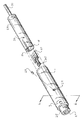
図5は、オフセット磁束センサを備えた磁気角度位置検出器の実施形態の組立分解斜視図である。図6は、オートバイのスロットルの角度位置を感知するために使用されるこの検出器の断面図である。図5及び6に示すように、対向する円筒形磁石3は、直径及び長さが約0.125インチであり、円筒形ハウジング1の凹部内に添付されて埋め込まれる。これらの磁石は、円筒形ハウジング1内に約0.45インチの距離で間隔を置いて配置される。厚さが約0.03インチの回路基板21は、回路基板21を収容する、円筒形ハウジング1内に配置された内部シリンダ23の成形レール18上に担持される。レール18は、回路基板の作動位置を見つけるために使用される端部止めを有する。回路基板21は、回路基板の端部の各反対側に取付けられて回路基板及びシリンダ23が円筒形ハウジング1内に完全に収容された時に磁石3の対称線9とオフセットの関係で配置された磁束センサ5の出力を処理及び/又は中継するのに必要ないかなる電子構成要素も有している。磁石3が円筒形ハウジング1内で回転する時、磁束は、センサ5のオフセット上面に垂直に検出される。円筒形ハウジング1が回転する間、内部シリンダ23は静止状態で保持される。構成要素の上述の寸法は、例示的な実施形態を開示するために提供されたものであり、他の寸法も使用することができる。
FIG. 5 is an exploded perspective view of an embodiment of a magnetic angular position detector with an offset magnetic flux sensor. FIG. 6 is a cross-sectional view of this detector used to sense the angular position of a motorcycle throttle. As shown in FIGS. 5 and 6, the opposing
図5に示すように、磁束センサ5は、回路基板21上に各々同じ大きさのオフセットで、共有磁石3の対称線9の両側に配置することができる。この構成に必要な空間を増すことが可能な場合は、回路基板の同じ側に互いに隣り合わせでデュアルセンサを配置することもできるであろう。デュアル磁束センサは、磁石が回転する時に重複する角度位置を読み取るのに使用してもよい。二重の読取値は、電子的に比較されて角度位置感知機構が正しく作動していることを確認することができる。2つのセンサの読取値の間に著しい変化が検出された場合、関連するエンジンのスロットルは、自動的に安全なアイドリングモードで作動して危険な作動条件を回避する。勿論、重複が要求されない場合は、回路基板21は、角度位置を検出するための単一センサだけをサポートすることができる。
As shown in FIG. 5, the magnetic flux sensors 5 can be arranged on both sides of the symmetry line 9 of the shared
図5及び6の装置の作動時に、円筒形ハウジング1は、オートバイのハンドルバーのチューブ内で回転するように配置される。外側シリンダ1の露出端25は、ハンドルバーの開放端から延びて、オートバイエンジンを制御するために、係合され、手動でねじられる円筒形スロットルグリップ(図示せず)と係合する。スロットルグリップは、ハンドルバーの上を摺動し、円筒形ハウジング1及び円筒形スロットルグリップ間の確実な摩擦嵌合をもたらすために端部25内の摩擦突起27と係合する一体型端部キャップ(図示せず)を有する。従って、円筒形ハウジング1は、エンジンを制御するためにスロットルグリップがねじられて回転された時にハンドルバー内で回転する。
円筒形ハウジング1の許容される回転角度は、内側シリンダ23内に形成された凹部30に挿入されて例えば接着剤によって添付されたペグ28によって制限される。ペグ28は、円筒形ハウジング1内に形成された弓形スロット29と摺動係合して延びる。例えば、スロットの長さは、スロットルグリップ及び円筒形ハウジング1に対して±45°のねじり回転をもたらすのに必要な寸法にされる。
In operation of the apparatus of FIGS. 5 and 6, the cylindrical housing 1 is arranged to rotate within the tube of a motorcycle handlebar. The exposed
The permissible rotation angle of the cylindrical housing 1 is limited by a
内側シリンダ23は、非鉄又は非磁性材料、例えばプラスチックで作られ、外側円筒形ハウジング1は、金属又はプラスチックで作られる。円筒形ハウジング1が大きな妨害を受けることなく内側シリンダ23上で回転するように、シリンダの材料は、摩擦係数が適度に小さくなければならない。静止内側シリンダ23は、回路基板17からの電線(図示せず)が電子制御装置まで通されてエンジンを制御するために関連する信号が中継される中空ネック部分31を有する。例えばクルーズ制御として作用する位置にスロットルグリップ及びセンサを保持するために、電気クラッチ(図示せず)を追加することができる。
The
磁気的に飽和したサマリウムコバルト(SmCo)磁石が、角度位置の検出のために望ましい作動を提供することが見出されている。スイスのチューリッヒ所在のミクロナス・セミコンダクター・カンパニーから提供される例えば「Micronas HAL 401」のようなホール効果センサは、約±75°の回転に亘る磁束変化に相当する比較的精密で線形の電気信号を発生する。2つの磁石に対する磁束センサのオフセット配置は、磁石の比較的大きな角度変位に亘るセンサ出力の実質的に向上した線形性及び精度を達成する。 It has been found that magnetically saturated samarium cobalt (SmCo) magnets provide desirable actuation for angular position detection. Hall effect sensors such as the “Micronas HAL 401” from the Micronas Semiconductor Company in Zurich, Switzerland, provide a relatively precise and linear electrical signal corresponding to a change in magnetic flux over a rotation of approximately ± 75 °. appear. The offset placement of the flux sensor relative to the two magnets achieves substantially improved linearity and accuracy of sensor output over a relatively large angular displacement of the magnet.
間隔SPが13mm、磁石の直径が7mm、磁石の長さが3mmの典型的な磁石の角度検出の精度を図7に示す。この図に示すように、±30°に亘るこれらの構成要素の回転の検出に対して、オフセット比(SP/D)が約20において約0.1°の最小誤差が達成される。この誤差は、理論的な角度センサの出力角度を正確な入力角度と比較し、次に、誤差の量を予測することによって決定された。記録された誤差は、この理論モデルから特定された最大値である。磁束検出器が他の文献で提案されたように磁石の対称線に配置されると、SP/Dの比は、非常に大きな値(D=0の位置で無限大)に増大して、検出器は、1.0°の誤差、又は0.1°の最適誤差の約10倍の誤差に近いより高い付随した誤差を有する。より広い角度(すなわち、±45°、±60°、又は±75°)の計測が要求される場合、累進的に大きな感知誤差が発生する。しかし、これらの誤差は、SP/Dの比を調節することによって最小にすることができる。その結果、選択された角度の範囲に亘る角度検出の誤差を最小にするために、所定の磁石の配置、直径、及び長さに関して、磁束センサのオフセットが選択される。 FIG. 7 shows the accuracy of angle detection of a typical magnet having a distance SP of 13 mm, a magnet diameter of 7 mm, and a magnet length of 3 mm. As shown in this figure, a minimum error of about 0.1 ° is achieved at an offset ratio (SP / D) of about 20 for detection of rotation of these components over ± 30 °. This error was determined by comparing the theoretical angle sensor output angle with the correct input angle and then predicting the amount of error. The recorded error is the maximum value identified from this theoretical model. When the magnetic flux detector is placed in the symmetry line of the magnet as proposed in other literature, the SP / D ratio increases to a very large value (infinite at the position of D = 0) for detection. The instrument has a higher associated error which is close to an error of 1.0 ° or about 10 times the optimal error of 0.1 °. When a wider angle (ie, ± 45 °, ± 60 °, or ± 75 °) is required, progressively larger sensing errors occur. However, these errors can be minimized by adjusting the SP / D ratio. As a result, the flux sensor offset is selected for a given magnet placement, diameter, and length to minimize angle detection errors over a selected range of angles.
図8及び9は、使用する磁石の配置と直径は同じであるが、長さがそれぞれ12mmと48mmに増加した装置に関する誤差のデータを示す。図7〜図9のグラフは、所定の磁石のサイズと間隔に対して、誤差は、長さを約12mmに増すことにより減少し、長さを約48mmに増すことによりほんの僅かな更なる増加しか得られないことを示す。図7〜図9のグラフは、オフセット磁束センサを備えた角度位置検出器の性能を最適化するために使用される解析手法を明らかにする。 FIGS. 8 and 9 show error data for devices with the same magnet arrangement and diameter used, but with lengths increased to 12 mm and 48 mm, respectively. The graphs of FIGS. 7-9 show that for a given magnet size and spacing, the error is reduced by increasing the length to about 12 mm and only a slight further increase by increasing the length to about 48 mm. It can only be obtained. The graphs of FIGS. 7-9 reveal the analytical techniques used to optimize the performance of angular position detectors with offset flux sensors.
指定された角度限界内で正確かつ線形の計測値を生成する角度センサを導出する本方法は、次のようにまとめることができる。
1.磁気回路は、例えば「Ansoft Maxwell 3D静磁気ソフトウエア バージョン9.0」を使用してモデル化される。モデル化の処理は、磁石形状の作成、材料特性と磁気方向の割当て、モデルを解くこと、及び可能なセンサ位置を表示する様々な曲線に沿って磁界の値を抽出することによるデータの事後処理が必要である。
2.センサの出力が計算され、例えば「MS Excel 97」を使用して完全に線形の理想センサと比較される。計算は、磁界の値をデータ処理ソフトウエアにインポートし、計算された磁界のベクトル特性と使用された磁石センサのベクトル特性との観点からセンサ応答を計算することによって実行される。センサの値は、次にスケーリングされ、所定の回転範囲の線形理想曲線に対して最も良く適合するようにオフセットされる。スケーリングとオフセットは、所定のセンサオフセットDと角度範囲との組合せに関して解析された全ての角度位置に対して一定に保たれる。計算されたシステム出力は、次に線形出力と比較され、最大絶対誤差が記録されてグラフにされる。
3.様々なセンサ出力のグラフを考察し、線形性と、同じく許容範囲、用途の仕様、及び幾何学的制約とを考慮し、磁気回路内の磁石の所定の間隔、直径、及び長さに対して望ましいセンサオフセットを選択することにより、望ましい出力が選択される。
The present method for deriving an angle sensor that produces accurate and linear measurements within specified angular limits can be summarized as follows.
1. The magnetic circuit is modeled using, for example, “Ansoft Maxwell 3D magnetostatic software version 9.0”. Modeling processes include post-processing of data by creating magnet shapes, assigning material properties and magnetic directions, solving models, and extracting magnetic field values along various curves that display possible sensor positions is required.
2. The output of the sensor is calculated and compared to a fully linear ideal sensor using, for example, “MS Excel 97”. The calculation is performed by importing the value of the magnetic field into the data processing software and calculating the sensor response in terms of the calculated magnetic field vector characteristics and the used magnetic sensor vector characteristics. The sensor value is then scaled and offset to best fit the linear ideal curve for a given range of rotation. Scaling and offset remain constant for all angular positions analyzed for a given sensor offset D and angular range combination. The calculated system output is then compared to the linear output and the maximum absolute error is recorded and graphed.
3. Consider various graphs of sensor output, taking into account linearity as well as tolerances, application specifications, and geometric constraints, for a given spacing, diameter, and length of magnets in the magnetic circuit. By selecting the desired sensor offset, the desired output is selected.
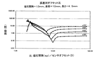
図10〜図13は、更に解析的方法の結果を明らかにし、それによって構成要素に対する最適パラメータが選択される。図10は、磁石間隔が13mm、磁石直径が10mm、及び磁石長さが4.5mmの検出器のために計算された誤差を示す。図11〜図13は、磁石の直径をそれぞれ16mm、24mm、及び52mmに変化させて実行された解析の結果を示す。図12に示すように、最小誤差は、磁石の直径24mmで達成される。しかし、図10及び図11に示すように、別のSP/D比を使用すれば、ごく僅かの誤差の増加で、より小さな磁石を使用することができる。 10-13 further reveal the results of the analytical method, whereby the optimal parameters for the component are selected. FIG. 10 shows the error calculated for a detector with a magnet spacing of 13 mm, a magnet diameter of 10 mm, and a magnet length of 4.5 mm. FIGS. 11 to 13 show the results of analyzes performed with the magnet diameter changed to 16 mm, 24 mm, and 52 mm, respectively. As shown in FIG. 12, the minimum error is achieved with a magnet diameter of 24 mm. However, as shown in FIGS. 10 and 11, if another SP / D ratio is used, a smaller magnet can be used with only a slight increase in error.
装置に対する比較的小さなサイズと最高の精度及び線形性とが要求される場合、図12の構成が選択される。図12の最大の誤差削減は、SP/Dが約5の比較的小さな比率の時に達成される。磁石の間隔SPは、図10〜図13の場合と同じなので、図12の誤差の減少は、磁束センサのオフセット距離Dの増加によってのみ達成され、装置のサイズに影響を与えないはずである。十分に定まった単一最小誤差がないので、図13の52mmの直径は選択されないであろう。また、図13の誤差は、図10〜図12の構成要素によって達成された最小値を超える。 If a relatively small size for the device and the highest accuracy and linearity are required, the configuration of FIG. 12 is selected. The maximum error reduction of FIG. 12 is achieved when the SP / D is a relatively small ratio of about 5. Since the magnet spacing SP is the same as in FIGS. 10-13, the reduction in error in FIG. 12 should be achieved only by increasing the offset distance D of the magnetic flux sensor and should not affect the size of the device. Since there is no well-defined single minimum error, the 52 mm diameter of FIG. 13 would not be selected. Also, the error of FIG. 13 exceeds the minimum value achieved by the components of FIGS.
図10〜図13はまた、磁石の直径が10mmから24mmに増加し、SP/D比が減少してオフセットの増加を示す時に、所定の構成要素の寸法で計測誤差が減少することを明らかにする。このデータセットで磁石の直径が24mmを超えて増加すると、感知誤差の増加がもたらされ、従って、最適な感知作動が要求される場合は望ましくない。ここで、本発明の解析的方法は、オフセット磁束センサを使用する全ての角度位置検出器の作動を最適化するのに使用することができることを理解すべきである。また、本発明は、磁石の直径、長さ、及び間隔のパラメータのみの調節に制限されない。角度の計測値を最適化するために、他のパラメータを開示の方法で調節して解析することができる。例えば、性能を最適化するために、磁束センサをシリンダの回転軸上の一点の周りの相対的回転から離して移動させる効果を判断することができるであろう。勿論、他のいかなる物理パラメータの変化も評価することができる。 FIGS. 10-13 also reveal that the measurement error decreases for a given component dimension when the magnet diameter increases from 10 mm to 24 mm and the SP / D ratio decreases to indicate an increase in offset. To do. Increasing the magnet diameter beyond 24 mm in this data set results in an increase in sensing error and is therefore undesirable when optimal sensing operation is required. Here, it should be understood that the analytical method of the present invention can be used to optimize the operation of all angular position detectors using offset flux sensors. Also, the present invention is not limited to adjusting only the magnet diameter, length, and spacing parameters. Other parameters can be adjusted and analyzed in the disclosed manner to optimize angle measurements. For example, to optimize performance, it would be possible to determine the effect of moving the magnetic flux sensor away from relative rotation about a point on the axis of rotation of the cylinder. Of course, any other changes in physical parameters can be evaluated.
図14は、拡張された範囲に亘って角度位置を精密に感知する装置を示す。この実施形態では、それぞれ独自の磁束検出器37を備えた二対33の磁石が使用される。サポート39が回転する時に、一対の磁石とそれに関連したセンサとが所定の最適角度範囲に亘って角度位置を検出する。この範囲を超えると、次の角度の範囲に亘って角度位置を精密に検出するために、第2の磁石の対とセンサとが使用される。角度位置を検出するための各磁石対とそのセンサとを交替に選択し、同時に他の磁石対によって生成されたデータを消すか又は無視するために、公知の電子ゲート回路を使用することができる。また、磁石対は、それらを隔てている距離又は磁束シールド40のいずれかによって互いに分離される。このようにして、±90°を超えて恐らくは±180°に至る範囲に亘り、精密かつ線形の計測値が取られる。上述のように例えば円筒形ハウジング1によって磁石3を回転させ、サポート39を静止状態に維持することによってもこれらの改善された結果を得ることができることは勿論である。
FIG. 14 shows an apparatus for precisely sensing angular position over an extended range. In this embodiment, two pairs of 33 magnets, each with its own
図15aは、拡張された範囲に亘って角度移動を検出するための装置の別の実施形態を示す。この装置は、異なる範囲の角度位置を検出するために直角に配置された2つの磁束センサを使用する。図15aに示すように、1つの磁束センサは、図示する向きの磁石の動きを検出する。図15bは、別の磁束センサで動きを検出するための磁石の向きを示す。磁束センサは、同じ量Dだけオフセットされるか、又は、必要に応じて作動結果を改善するためにオフセットを変化させることができる。 FIG. 15a shows another embodiment of an apparatus for detecting angular movement over an extended range. This device uses two magnetic flux sensors arranged at right angles to detect different ranges of angular positions. As shown in FIG. 15a, one magnetic flux sensor detects the movement of the magnet in the orientation shown. FIG. 15b shows the orientation of the magnet for detecting movement with another magnetic flux sensor. The magnetic flux sensors can be offset by the same amount D, or the offset can be varied to improve the operating results as needed.
図16は、拡張された範囲に亘って回転を検出するために、オフセットDで三角形に配置された3つの磁束センサを使用する別の実施形態を示す。図17は、重複した感知のために二対の磁束センサを使用し、拡張された範囲に亘って回転を検出するために、オフセットDで4つの磁束センサを使用する実施形態を示す。それぞれのセンサ対の対向するセンサ構成要素は、大きさが同じで、磁界方向が180°変化した相対的方向が反対の重複した角度位置を検出し、従って、センサ対の構成要素のセンサの読取値は、同じ角度範囲で線形である。上述のように、信頼性又は診断機能を付加するために重複読取値を使用することができる。また、グループ内のセンサに対して別のオフセットを使用することができる。図16及び図17の実施形態は、センサ及びそれらの磁石間の相対的な角度移動に応答して、連続して作動する磁束センサ又は磁束センサ対の各々からデータを読み取るために電子ゲートを必要とする場合がある。 FIG. 16 shows another embodiment using three magnetic flux sensors arranged in a triangle with an offset D to detect rotation over an extended range. FIG. 17 illustrates an embodiment using two pairs of flux sensors for overlapping sensing and using four flux sensors at offset D to detect rotation over an extended range. The opposing sensor components of each sensor pair detect overlapping angular positions that are the same size and opposite in relative direction with a 180 ° change in the magnetic field direction, and thus the sensor readings of the sensor pair components. The value is linear over the same angular range. As described above, duplicate readings can be used to add reliability or diagnostic capabilities. Also, another offset can be used for the sensors in the group. The embodiment of FIGS. 16 and 17 requires an electronic gate to read data from each of the continuously operating flux sensors or flux sensor pairs in response to relative angular movement between the sensors and their magnets. It may be.
図18は、自動車エンジン制御のための角度位置センサの構成要素の分解組立斜視図である。センサハウジング41は、上述した方法で間隔を空けて配置された2つの対向する磁石3を保持するロータ43を支持する。例えばホール効果センサである磁束センサ5は、ハウジング41の裏面に圧接されて埋め込まれたプリント基板45と係合する。磁束センサ5は、上述のように、磁石3間の所定位置に保持され、磁石の対称軸からオフセットされる。前面カバー47は、全ての構成要素を保持するためにハウジング41と係合される。
FIG. 18 is an exploded perspective view of components of an angular position sensor for automobile engine control. The sensor housing 41 supports a
ロータ43は、自動車エンジン(図示せず)吸気マニホルドのスロットル本体に配置された従来のバタフライバルブ(図示せず)と回転のために係合される。作動時には、自動車のアクセルペダル(図示せず)が作動すると、それは機械的にバタフライバルブにリンクされ、従って、アクセルペダルの動きは、従来の方法でバタフライバルブの対応する動きを引き起こす。ロータ43は、バタフライバルブと共に±45°回転し、磁束センサ5は、バタフライバルブの角度位置と関連するアクセルペダルの作動位置とに対応する電気信号を生成する。この信号は、自動車エンジンを従来の方法で制御するために磁束センサの角度位置情報を使用する従来のエンジン制御コンピュータに入力として加えられる。
The
代替実施形態では、上述の機能を備えた角度位置センサは、アクセルペダル及び吸気マニホルドのバタフライバルブの両方に結合することができる。アクセルペダルセンサは、次に、アクセルペダルの角度位置を検出し、バタフライバルブを対応する位置まで回転させるように制御信号を送信するか、又はバタフライバルブに機械的に連結されたままであるアクセルペダルの角度位置をモニタするだけかのいずれかである。どちらの場合も、これらの構成要素の適正な同期作動を確認するために、アクセルペダルの感知された角度位置は、バタフライバルブの感知された角度位置と比較することができる。アクセルペダルの感知された角度位置とバタフライバルブの感知された角度位置とが互いに一致する場合、対応する角度位置情報は、制御コンピュータのデータとして加えられるであろう。感知位置が一致しない場合、安全予防策として、エンジンをアイドリング条件で運転するのが良い。 In an alternative embodiment, an angular position sensor with the functions described above can be coupled to both the accelerator pedal and the intake manifold butterfly valve. The accelerator pedal sensor then detects the angular position of the accelerator pedal and sends a control signal to rotate the butterfly valve to the corresponding position, or the accelerator pedal that remains mechanically coupled to the butterfly valve. Either just monitor the angular position. In either case, the sensed angular position of the accelerator pedal can be compared to the sensed angular position of the butterfly valve to confirm proper synchronized operation of these components. If the sensed angular position of the accelerator pedal and the sensed angular position of the butterfly valve coincide with each other, the corresponding angular position information will be added as control computer data. If the sensing positions do not match, the engine should be operated under idling conditions as a safety precaution.
オートバイ又は自動車のスロットルの角度位置の検出に使用するための角度位置センサを開示したが、センサは、任意の装置の回転位置を検出するのに使用することができることを理解すべきである。また、実施形態は、円筒形ハウジングの動きに関連して説明したが、関連する磁束センサが望ましいオフセットで配置される限り、任意の望ましい形状のハウジングを使用することができることを認めるべきである。更に、開示の実施形態には、円筒形磁石が示されて製造にも好ましいが、例えば正方形、矩形、又はL字形のような任意形状の磁石を使用することができ、更に対向する磁石の形状が異なっていても使用することができる。また、磁束センサと一対の磁石との間の相対的な動きは、任意の望ましい経路に亘って達成することができる。しかし、磁気的及び幾何学対称線9と回転軸11とに関して同心の円弧として形成された経路が望ましい。勿論、開示した本発明の解析的方法は、角度位置感知装置に対する任意の選択経路、磁石の形状、又は構成要素の他の任意の変更、又は、構成要素の向き又はサイズの有効性を評価するのに使用することができると考えられる。
開示の実施形態の変形及び修正は、従って、本発明の範囲を逸脱することなく行うことができる。上述の説明は、従って限定的ではなく例示的であるように意図されており、特許請求の範囲及びその均等物が本発明の範囲を示すことを理解すべきである。
While an angular position sensor for use in detecting the angular position of a motorcycle or automobile throttle has been disclosed, it should be understood that the sensor can be used to detect the rotational position of any device. Also, although the embodiments have been described in connection with the movement of a cylindrical housing, it should be appreciated that any desired shaped housing can be used as long as the associated magnetic flux sensor is positioned at the desired offset. Further, although the disclosed embodiment shows a cylindrical magnet, which is preferred for manufacturing, any shape of magnet can be used, such as square, rectangular, or L-shaped, and the shape of the opposing magnet Can be used even if they are different. Also, relative movement between the flux sensor and the pair of magnets can be achieved over any desired path. However, a path formed as a concentric arc with respect to the magnetic and geometric symmetry line 9 and the axis of
Variations and modifications of the disclosed embodiments may thus be made without departing from the scope of the invention. The foregoing description is thus intended to be illustrative rather than limiting, and it is to be understood that the claims and their equivalents indicate the scope of the invention.
1 シリンダ
3 対向する一対の磁石
5 磁束センサ
7 感知面
9 幾何学的及び磁気的対称の仮想線
SP 磁石の間隔
DESCRIPTION OF SYMBOLS 1
Claims (19)
磁界感知面を有し、前記磁石間に配置され、該磁界感知面が前記対称線と交差しないように該対称線から所定のオフセット距離だけ離れた間隔で配置された少なくとも1つの磁束センサと、
を含み、
前記センサは、それによって、前記磁石対及び前記センサ間の相対的角度移動に応答して磁束の比較的線形の変化を感知する、
ことを特徴とする角度位置センサ。 At least a pair of magnets having opposing opposite poles arranged in a spaced relationship and forming a geometric and magnetic symmetry line therebetween;
At least one magnetic flux sensor having a magnetic field sensing surface, disposed between the magnets, and spaced at a predetermined offset distance from the symmetry line so that the magnetic field sensing surface does not intersect the symmetry line;
Including
The sensor thereby senses a relatively linear change in magnetic flux in response to a relative angular movement between the magnet pair and the sensor;
An angular position sensor characterized by the above.
前記軸線に垂直でそれと交差する線の反対端において前記円筒形スロットル制御部内に間隔を空けた関係で配置され、対向する反対の極を有してその間の幾何学的及び磁気的対称線を形成する少なくとも一対の磁石と、
磁界感知面を有し、前記磁石間に配置され、前記対称線から所定のオフセット距離だけ離れた間隔で配置された少なくとも1つの磁束センサと、
を含み、
前記磁束センサは、それによって、前記円筒形スロットル制御部及び磁石が該センサに対して回転する時に磁束の比較的線形の変化を感知する、
ことを特徴とする電子スロットル位置センサ。 A non-magnetic cylindrical throttle control for rotationally twisting on an axis to control motorcycle acceleration;
Arranged in a spaced relationship within the cylindrical throttle control at the opposite end of the line perpendicular to and intersecting the axis and having opposing opposite poles to form geometric and magnetic symmetry lines therebetween At least a pair of magnets,
At least one magnetic flux sensor having a magnetic field sensing surface, disposed between the magnets and spaced apart from the symmetry line by a predetermined offset distance;
Including
The magnetic flux sensor thereby senses a relatively linear change in magnetic flux as the cylindrical throttle control and magnet rotate relative to the sensor.
An electronic throttle position sensor.
前記円筒形ハウジング上に、反対の極が対向するように、該ハウジングの直径の反対端に間隔を空けて一対の磁石を添付する段階と、
前記円筒形ハウジング内に少なくとも1つの磁束センサを取り付け、前記磁石間の対称線から所定の固定距離だけオフセットさせる段階と、
前記円筒形ハウジング及び磁石が前記磁束センサに対して前記軸線の周りに所定の角度だけ回転した時に、磁束の線形変化を検出する段階と、
を含むことを特徴とする、角度位置を検出する方法。 Rotating the cylindrical housing about its axis;
Attaching a pair of magnets to the opposite ends of the diameter of the housing such that opposite poles face each other on the cylindrical housing;
Mounting at least one magnetic flux sensor within the cylindrical housing and offsetting it from a symmetry line between the magnets by a predetermined fixed distance;
Detecting a linear change in magnetic flux when the cylindrical housing and magnet rotate a predetermined angle about the axis relative to the magnetic flux sensor;
A method for detecting an angular position, comprising:
前記それぞれの対に対して異なる所定の角度距離に亘る磁束の線形変化を検出する段階と、
を含むことを特徴とする請求項15に記載の方法。 Using two or more pairs of magnets and associated magnetic flux sensors;
Detecting a linear change in magnetic flux over different predetermined angular distances for each pair;
The method according to claim 15, comprising:
Applications Claiming Priority (1)
| Application Number | Priority Date | Filing Date | Title |
|---|---|---|---|
| US10/464,704 US6960973B2 (en) | 2003-06-18 | 2003-06-18 | Angular position sensor |
Publications (2)
| Publication Number | Publication Date |
|---|---|
| JP2005010164A JP2005010164A (en) | 2005-01-13 |
| JP4035520B2 true JP4035520B2 (en) | 2008-01-23 |
Family
ID=33418160
Family Applications (1)
| Application Number | Title | Priority Date | Filing Date |
|---|---|---|---|
| JP2004181094A Expired - Fee Related JP4035520B2 (en) | 2003-06-18 | 2004-06-18 | Angular position sensor |
Country Status (3)
| Country | Link |
|---|---|
| US (2) | US6960973B2 (en) |
| EP (1) | EP1489378A3 (en) |
| JP (1) | JP4035520B2 (en) |
Families Citing this family (20)
| Publication number | Priority date | Publication date | Assignee | Title |
|---|---|---|---|---|
| US20050068024A1 (en) * | 2003-09-29 | 2005-03-31 | Byram Robert James | Rotary position sensor |
| JP4401926B2 (en) * | 2004-10-14 | 2010-01-20 | ヤマハ発動機株式会社 | Relative position detection control device and saddle riding type vehicle |
| JP4911889B2 (en) * | 2004-10-14 | 2012-04-04 | ヤマハ発動機株式会社 | Relative position detection device and saddle riding type vehicle |
| JP2006112879A (en) * | 2004-10-14 | 2006-04-27 | Yamaha Motor Co Ltd | Relative position detector and saddle ride type vehicle |
| EP1830162B1 (en) * | 2004-12-14 | 2015-04-01 | NTN Corporation | Rotation detecting apparatus and bearing provided with same |
| DE102005012622A1 (en) * | 2005-03-18 | 2006-09-21 | Siemens Ag | Method for regulating output of motorcycle involves determination of rotating position of handle whereby collected rotating position is supplied by sensor lines to throttle valve or slider or to controller |
| US7304472B2 (en) * | 2005-04-28 | 2007-12-04 | Williams Controls Industries, Inc. | Rotary position sensor |
| DE202005016726U1 (en) * | 2005-10-24 | 2007-03-01 | Rema Lipprandt Gmbh & Co. Kg | Driving switch for controlling a traction drive of a power-driven industrial truck |
| KR101382515B1 (en) | 2006-09-29 | 2014-04-07 | 각코호진 와세다다이가쿠 | Medical technique evaluation system, technique evaluation device, technique evaluation device program |
| JP4870226B2 (en) * | 2008-03-04 | 2012-02-08 | アルプス電気株式会社 | Position detection device |
| KR101095032B1 (en) * | 2009-05-20 | 2011-12-20 | 에스엘 주식회사 | Apparatus for electron control transmission |
| JP5105266B2 (en) | 2010-06-02 | 2012-12-26 | 株式会社デンソー | Rotation angle detector |
| WO2013022390A1 (en) * | 2011-08-08 | 2013-02-14 | Husqvarna Ab | A magnet holder for use in a throttle position sensor, a magnet holder for use in an angular position sensor, and methods for manufacturing them |
| US9244090B2 (en) | 2012-12-18 | 2016-01-26 | Trail Tech, Inc. | Speed sensor assembly |
| DE102013216093B4 (en) * | 2013-08-14 | 2016-06-02 | Carl Zeiss Industrielle Messtechnik Gmbh | Reduction of errors of a rotating device, in particular for the determination of coordinates of a workpiece or the machining of a workpiece |
| KR101602062B1 (en) | 2014-10-07 | 2016-03-21 | 주식회사 현대케피코 | Apparatus and method for measuring magnet flux for the rotation detecting sensor |
| JP6289399B2 (en) * | 2015-02-23 | 2018-03-07 | 本田技研工業株式会社 | Position detection device |
| JP2017045190A (en) * | 2015-08-25 | 2017-03-02 | 株式会社東海理化電機製作所 | Position sensor |
| US10385605B2 (en) | 2016-11-16 | 2019-08-20 | Vermeer Manufacturing Company | Tailgate sensor |
| US10850723B2 (en) | 2017-08-11 | 2020-12-01 | Vermeer Manufacturing Company | Self-propelled vehicles having a steering position sensor |
Family Cites Families (10)
| Publication number | Priority date | Publication date | Assignee | Title |
|---|---|---|---|---|
| JPS56107119A (en) | 1980-01-30 | 1981-08-25 | Nippon Denso Co Ltd | Detecting device for rotational angle |
| JP3206204B2 (en) * | 1992-05-22 | 2001-09-10 | 株式会社デンソー | Throttle position sensor |
| US6137288A (en) | 1998-05-08 | 2000-10-24 | Luetzow; Robert Herman | Magnetic rotational position sensor |
| JP4378814B2 (en) * | 1999-07-16 | 2009-12-09 | 株式会社日本自動車部品総合研究所 | Rotation angle detector |
| US6489761B1 (en) | 1999-09-09 | 2002-12-03 | Delphi Technologies, Inc. | Magnetic arrangement for an analog angle encoder |
| JP3600114B2 (en) * | 2000-04-04 | 2004-12-08 | 株式会社デンソー | Rotation angle detector |
| JP4291936B2 (en) * | 2000-07-12 | 2009-07-08 | カヤバ工業株式会社 | Rotation angle sensor |
| JP3511171B2 (en) * | 2001-03-30 | 2004-03-29 | 富士通カンタムデバイス株式会社 | High frequency semiconductor device |
| US6703829B2 (en) * | 2001-09-07 | 2004-03-09 | Jeff Tola | Magnetic position sensor |
| US6806702B2 (en) * | 2002-10-09 | 2004-10-19 | Honeywell International Inc. | Magnetic angular position sensor apparatus |
-
2003
- 2003-06-18 US US10/464,704 patent/US6960973B2/en not_active Expired - Lifetime
-
2004
- 2004-05-20 EP EP04252945A patent/EP1489378A3/en not_active Withdrawn
- 2004-06-18 JP JP2004181094A patent/JP4035520B2/en not_active Expired - Fee Related
-
2005
- 2005-06-15 US US11/153,808 patent/US20050231883A1/en not_active Abandoned
Also Published As
| Publication number | Publication date |
|---|---|
| EP1489378A3 (en) | 2006-02-08 |
| US6960973B2 (en) | 2005-11-01 |
| JP2005010164A (en) | 2005-01-13 |
| EP1489378A2 (en) | 2004-12-22 |
| US20040257067A1 (en) | 2004-12-23 |
| US20050231883A1 (en) | 2005-10-20 |
Similar Documents
| Publication | Publication Date | Title |
|---|---|---|
| JP4035520B2 (en) | Angular position sensor | |
| JP4115388B2 (en) | Butterfly valve connection piece | |
| CA2143810C (en) | Internal combustion engine throttle position sensor | |
| CA2143919C (en) | Rotary position sensor with improved bearing tolerance | |
| JP5079816B2 (en) | Preferably a magnetic position sensor having a magnet shape that varies pseudo-sinusoidally. | |
| US8970210B2 (en) | Bidirectional magnetic position sensor having field rotation | |
| JP6359079B2 (en) | Hall sensor insensitive to external magnetic field | |
| JP2000028312A (en) | Low profile non-contacting position sensor | |
| US6972558B1 (en) | Magnetic sensor system | |
| JP6651962B2 (en) | Position detection device | |
| US7710110B2 (en) | Rotary sensor with rotary sensing element and rotatable hollow magnet | |
| JP2007263854A (en) | Rotation angle detecting device | |
| US6930477B1 (en) | Rotation angle detection device | |
| US6396260B1 (en) | Measuring device for contactless detection of a rotational angle | |
| JP5757285B2 (en) | Position detection device | |
| JP2014113881A (en) | Throttle grip device | |
| US7219562B2 (en) | Angle sensor | |
| JP2002530637A (en) | Measuring device for non-contact detection of rotation angle | |
| JPH11211410A (en) | Non-contact position sensor | |
| US10060760B2 (en) | Magnetix flux position detector that detects the magnetic flux at minimum position along a magnetic circuit | |
| KR101518899B1 (en) | Accelerator pedal angle detecting device for vehicle | |
| JP3855763B2 (en) | Rotation angle detector | |
| JP7431120B2 (en) | accelerator position sensor | |
| US6885189B1 (en) | Measuring instrument for contactless detection of an angle of rotation | |
| JP2010223656A (en) | Angle sensor and turning angle detecting device using the same |
Legal Events
| Date | Code | Title | Description |
|---|---|---|---|
| A711 | Notification of change in applicant |
Free format text: JAPANESE INTERMEDIATE CODE: A712 Effective date: 20060622 |
|
| A131 | Notification of reasons for refusal |
Free format text: JAPANESE INTERMEDIATE CODE: A131 Effective date: 20061016 |
|
| A521 | Written amendment |
Free format text: JAPANESE INTERMEDIATE CODE: A523 Effective date: 20070115 |
|
| TRDD | Decision of grant or rejection written | ||
| A01 | Written decision to grant a patent or to grant a registration (utility model) |
Free format text: JAPANESE INTERMEDIATE CODE: A01 Effective date: 20071001 |
|
| A61 | First payment of annual fees (during grant procedure) |
Free format text: JAPANESE INTERMEDIATE CODE: A61 Effective date: 20071029 |
|
| FPAY | Renewal fee payment (event date is renewal date of database) |
Free format text: PAYMENT UNTIL: 20101102 Year of fee payment: 3 |
|
| R150 | Certificate of patent or registration of utility model |
Free format text: JAPANESE INTERMEDIATE CODE: R150 |
|
| FPAY | Renewal fee payment (event date is renewal date of database) |
Free format text: PAYMENT UNTIL: 20111102 Year of fee payment: 4 |
|
| FPAY | Renewal fee payment (event date is renewal date of database) |
Free format text: PAYMENT UNTIL: 20121102 Year of fee payment: 5 |
|
| FPAY | Renewal fee payment (event date is renewal date of database) |
Free format text: PAYMENT UNTIL: 20121102 Year of fee payment: 5 |
|
| FPAY | Renewal fee payment (event date is renewal date of database) |
Free format text: PAYMENT UNTIL: 20131102 Year of fee payment: 6 |
|
| LAPS | Cancellation because of no payment of annual fees |