JP4035403B2 - Feeding container - Google Patents
Feeding container Download PDFInfo
- Publication number
- JP4035403B2 JP4035403B2 JP2002254286A JP2002254286A JP4035403B2 JP 4035403 B2 JP4035403 B2 JP 4035403B2 JP 2002254286 A JP2002254286 A JP 2002254286A JP 2002254286 A JP2002254286 A JP 2002254286A JP 4035403 B2 JP4035403 B2 JP 4035403B2
- Authority
- JP
- Japan
- Prior art keywords
- container
- contents
- rotating body
- screw rod
- convex portion
- Prior art date
- Legal status (The legal status is an assumption and is not a legal conclusion. Google has not performed a legal analysis and makes no representation as to the accuracy of the status listed.)
- Expired - Lifetime
Links
Images


Description
【0001】
【発明の属する技術分野】
本発明は、容器本体内に収納した内容物を押し上げて塗布ヘッドの表面上に排出し該内容物の塗布を可能とする繰り出し容器に関するものであって、内容物を押し出したときに生じる残存圧に起因した必要以上の排出を確実に防止しようとするものである。
【0002】
【従来の技術】
粘度が比較的高い固形あるいはクリーム状の内容物を塗布ヘッドに適量排出して直接塗布することができる繰り出し容器は、容器本体内に収納、保持した内容物を塗布ヘッドの開孔部分から押し出すことができるように、その底部に繰り出し機構が組み込まれている。
【0003】
この繰り出し機構は、内容物を保持する中皿とこの中皿に一体的に連結するスクリューロッドとこのスクリューロッドに係合してその回動にて中皿をスクリューロッドとともに塗布ヘッドに向けてスライドさせる回転部材にて構成されていて、回転部材の回転度合いによって排出量の調整が行なえるようになっている。
【0004】
ところで、従来の繰り出し容器は、中皿をスライドさせて内容物を排出した場合、その際の押圧力が容器内の内容物にそのまま残存するため回転部材の回転を停止させた状態にあるにもかかわらず、内容物が塗布ヘッドの開孔から排出される不具合があり内容物の効率的な排出ができないところに問題を残していた。
【0005】
本発明の課題は、繰り出し容器において従来問題となっていた残存圧に起因した内容物の必要以上の排出を防止できる新規な構造について提案するところにある。
【0006】
【課題を解決するための手段】
本発明は、内容物を収納する容器本体と、この容器本体の口部に装着されその外表面に容器本体の内側に通じる複数の開孔を有する塗布ヘッドと、容器本体内に収納された内容物を押し上げて塗布ヘッドの開孔を通して排出させる容器であって、
内容物を保持し容器本体の内壁に沿って摺動可能な中皿と、この中皿の背面にて連結するスクリューロッドと、このスクリューロッドを移動可能に支えるベースと、容器本体の底壁及びベースの相互間にて弾性支持されその回転にて中皿をスクリューロッドとともに塗布ヘッドに向けてスライドさせる回転体とを備え、
前記回転体に、その回転中、スクリューロッドを中皿とともに極僅かに上下動させて内容物のバックサクションを誘導する振動手段を設けたことを特徴とする繰り出し容器である。
【0007】
上記の構成になる繰り出し容器において振動手段は、ベースに設けられた凸部と、このベースに接触する回転体の底面に設けられ該凸部に適合する凹部からなるもの、あるいは、回転体に設けられた凸部と、この回転体に接触する容器本体の底壁に設けられ該凸部に適合する凹部からなるものにて構成することができる。
【0008】
【発明の実施の形態】
以下、図面を用いて本発明をより具体的に説明する。
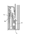
図1(a)(b)は本発明に従う繰り出し容器の構成を模式的に示した図である。
【0009】
図1において1は内容物Pを収納する容器本体である。この容器本体1は内容器1aと外容器1bとを組み合わせて構成することができる。
【0010】
また、2は容器本体1の口部に装着される塗布ヘッドであって、その外表面には容器本体1の内側に通じる複数の開孔2aが設けられている。
【0011】
3は塗布ヘッド2を覆うように容器本体1に取り付けられるオーバーキャップ、4は容器本体内に収納された内容物を押し上げ塗布ヘッド2の開孔2aを通して外表面に排出する繰り出し手段である。
【0012】
繰り出し手段4は内容物を保持し内容器1aの内壁に沿って摺動可能な中皿4aと、この中皿4aの背面(下端)にて連結するスクリューロッド4bと、このスクリューロッド4bを移動可能に支えるベース4cと、内容器1aの底壁及びベース4cの相互間にて弾性支持されその回転にて中皿4aをスクリューロッド4bとともに塗布ヘッド2に向けてスライドさせる回転体4dからなっている。
【0013】
また、5は回転体4dを内容器1aとベース4cの間で弾性支持するための切り起こし舌片状の板ばね、6は回転体4dの回転中にスクリューロッド4bを中皿4aとともに極僅かに上下動させて内容物Pのバックサクションを誘導する振動手段である。この振動手段6はベース4cの環状体に間隔をおいて設けられた鋸刃状の凸部6aとこのベース4cに接触する回転体4dの底面に設けられ該凸部6aに適合する形状を有する図4に示すような凹部6bからなっていて、これにより回転体4dの一方向のみの回転を許容するラチェットを構成しスクリューロッド4bを中皿4aとともに極僅かに上下動させながら定量排出を行う。
【0014】
内容物Pを排出すべく、オーバーキャップ3を取り外して回転体4dを回転させるとこの回転体4dにねじ係合するスクリューロッド4bがベース4cのガイドgに沿って中皿4aとともに塗布ヘッド2に向かって直線的に移動していき、これにより中皿4aに保持された内容物Pが押し上げられ塗布ヘッド2の開孔2aから排出される。
【0015】
このとき、回転体4dに設けられた凹部6bはベース4cの環状体に設けられた凸部6aを次々と乗り越えながら移動するため、該回転体4d、スクリューロッド4b、中皿4a、内容物Pはスクリューロッド4bの軸心Lに沿う向きに上下動(振動)する。
【0016】
内容物Pの排出をやめるべく回転体4dを停止させると回転体4dが容器本体1の底部に向けて下降する分だけ中皿4aが容器本体1内に引き込まれる、いわゆるバックサクションが誘導され、それがため内容物Pの排出に負荷される押圧力はすぐさま解除されることとなり残存圧によって内容物が必要以上に排出されることはない。
【0017】
回転体4dは一方向のみの回転を許容したラチェット式として図示したが、凸部6aおよび凹部6bにつき、なだらかな傾斜を設けて逆向きに回転させる構造としてもよくこの構造によれば必要に応じて内容物Pを容器内に引き込むことが可能となる。
【0018】
図2(a)〜(d)は本発明に従う繰り出し容器の他の構成を示したものである。
【0019】
この例は、その要部を図3(a)(b)に示すごとく、振動手段6のうちの凸部6aを回転体6dの先端部に下向きに設け、この凸部6aに適合する凹部6bを内容器1aの底壁に上向きに設けた構造のものであり、これによっても上掲図1に示した構造のものと同様のバックサクションを誘導することができる。
【0020】
回転体4dを容器本体1とベース4cの間で弾性支持する板ばね5は図1では、内容器1aの底壁を舌片状に切り起こした板ばねとして示したが、この板ばね5は、図3(b)に示すように、回転体4dの先端壁を舌片状に切り起こしたものを適用してもよい。
【0021】
また、凸部6a、凹部6bは、図4あるいは図5に示すような箇所に設けるようにしてもよく、凸部6a、凹部6bはベース4c、回転体4dの形状に応じてその設置箇所は適宜に変更することができる。
【0022】
【発明の効果】
本発明によれば、内容物を排出する際に容器内に残存圧が生じないので、必要以上に内容物が排出されることはなく、該内容物を効率よく使用することができる。
【図面の簡単な説明】
【図1】 本発明に従う繰り出し容器の実施の形態を示した図である。
【図2】 (a)〜(d)は本発明に従う繰り出し容器の他の実施の形態を示した図である。
【図3】 (a)(b)は図1に示した容器の要部の外観斜視図である。
【図4】 本発明に従う繰り出し容器の他の実施の形態をその要部について示した図である。
【図5】 本発明に従う繰り出し容器の他の実施の形態をその要部について示した図である。
【符号の説明】
1 容器本体
1a 内容器
1b 外容器
2 塗布ヘッド
2a 開孔
3 オーバーキャップ
4 繰り出し手段
4a 中皿
4b スクリューロッド
4c ベース
4d 回転体
5 板ばね
6 振動手段
6a 凸部
6b 凹部
g ガイド[0001]
BACKGROUND OF THE INVENTION
The present invention relates to a feeding container that pushes up the contents stored in the container body and discharges the contents onto the surface of the coating head so that the contents can be applied, and the residual pressure generated when the contents are pushed out. It is intended to surely prevent unnecessary discharge caused by the above.
[0002]
[Prior art]
A feeding container that can discharge a suitable amount of solid or cream-like contents with relatively high viscosity to the application head and apply it directly, pushes out the contents stored and held in the container body from the opening part of the application head. The feeding mechanism is built into the bottom of the machine.
[0003]
The feeding mechanism is configured to slide the middle plate toward the coating head together with the screw rod by engaging the screw rod and the screw rod integrally connected to the middle plate, and rotating the middle plate to hold the contents. It is comprised by the rotating member to be made, and discharge amount can be adjusted with the rotation degree of a rotating member.
[0004]
By the way, the conventional feeding container is in a state where the rotation of the rotating member is stopped because the pressing force at that time remains in the contents in the container when the contents are discharged by sliding the inner tray. Regardless, there is a problem in that the contents are discharged from the opening of the coating head and the contents cannot be discharged efficiently.
[0005]
An object of the present invention is to propose a novel structure capable of preventing unnecessary discharge of contents due to residual pressure, which has been a problem in the conventional delivery container.
[0006]
[Means for Solving the Problems]
The present invention relates to a container main body for storing contents, an application head having a plurality of openings attached to the outer surface of the container main body and connected to the inside of the container main body, and contents stored in the container main body. A container that pushes up an object and discharges it through the opening of the coating head,
An inner plate that holds the contents and is slidable along the inner wall of the container body, a screw rod that is connected to the back surface of the inner plate, a base that movably supports the screw rod, a bottom wall of the container body, and A rotating body that is elastically supported between the bases and slides the intermediate dish together with the screw rod toward the coating head by rotation thereof;
The feeding container is characterized in that the rotating body is provided with vibration means for guiding the back suction of the contents by slightly moving the screw rod up and down together with the inner plate during the rotation.
[0007]
In the feeding container having the above-described configuration, the vibration means includes a convex portion provided on the base and a concave portion provided on the bottom surface of the rotating body that contacts the base, and is provided on the rotating body. And a convex portion provided on the bottom wall of the container main body that comes into contact with the rotating body, and a concave portion that conforms to the convex portion.
[0008]
DETAILED DESCRIPTION OF THE INVENTION
Hereinafter, the present invention will be described more specifically with reference to the drawings.
1 (a) and 1 (b) are diagrams schematically showing the configuration of a feeding container according to the present invention.
[0009]
In FIG. 1, reference numeral 1 denotes a container body that stores the contents P. The container body 1 can be configured by combining an inner container 1a and an outer container 1b.
[0010]
[0011]
3 is an overcap attached to the container main body 1 so as to cover the
[0012]
The feeding means 4 holds the contents and is slidable along the inner wall of the inner container 1a, a
[0013]
In addition, 5 is a cut-and-raised plate-like leaf spring for elastically supporting the rotating
[0014]
When the overcap 3 is removed and the rotating
[0015]
At this time, since the
[0016]
When the rotating
[0017]
Although the rotating
[0018]
2 (a) to 2 (d) show other configurations of the feeding container according to the present invention.
[0019]
In this example, as shown in FIGS. 3 (a) and 3 (b), the
[0020]
The
[0021]
Further, the
[0022]
【The invention's effect】
According to the present invention, since no residual pressure is generated in the container when the contents are discharged, the contents are not discharged more than necessary, and the contents can be used efficiently.
[Brief description of the drawings]
FIG. 1 is a view showing an embodiment of a feeding container according to the present invention.
FIGS. 2A to 2D are views showing another embodiment of a feeding container according to the present invention.
FIGS. 3A and 3B are external perspective views of main parts of the container shown in FIG.
FIG. 4 is a view showing the main part of another embodiment of the feeding container according to the present invention.
FIG. 5 is a view showing a main part of another embodiment of the feeding container according to the present invention.
[Explanation of symbols]
DESCRIPTION OF SYMBOLS 1 Container main body 1a Inner container
Claims (3)
内容物を保持し容器本体の内壁に沿って摺動可能な中皿と、この中皿の背面にて連結するスクリューロッドと、このスクリューロッドを移動可能に支えるベースと、容器本体の底壁及びベースの相互間にて弾性支持されその回転にて中皿をスクリューロッドとともに塗布ヘッドに向けてスライドさせる回転体とを備え、
前記回転体に、その回転中、スクリューロッドを中皿とともに極僅かに上下動させて内容物のバックサクションを誘導する振動手段を設けたことを特徴とする繰り出し容器。A container main body for storing contents, an application head having a plurality of openings attached to the outer surface of the container main body and connected to the inside of the container main body, and the content stored in the container main body A container that is discharged through a hole in the coating head,
An inner plate that holds the contents and is slidable along the inner wall of the container body, a screw rod that is connected to the back surface of the inner plate, a base that movably supports the screw rod, a bottom wall of the container body, and A rotating body that is elastically supported between the bases and slides the intermediate dish together with the screw rod toward the coating head by rotation thereof;
A feeding container characterized in that the rotating body is provided with vibration means for guiding the back suction of the contents by slightly moving the screw rod up and down together with the inner plate during the rotation.
Priority Applications (1)
| Application Number | Priority Date | Filing Date | Title |
|---|---|---|---|
| JP2002254286A JP4035403B2 (en) | 2002-08-30 | 2002-08-30 | Feeding container |
Applications Claiming Priority (1)
| Application Number | Priority Date | Filing Date | Title |
|---|---|---|---|
| JP2002254286A JP4035403B2 (en) | 2002-08-30 | 2002-08-30 | Feeding container |
Publications (2)
| Publication Number | Publication Date |
|---|---|
| JP2004090976A JP2004090976A (en) | 2004-03-25 |
| JP4035403B2 true JP4035403B2 (en) | 2008-01-23 |
Family
ID=32060084
Family Applications (1)
| Application Number | Title | Priority Date | Filing Date |
|---|---|---|---|
| JP2002254286A Expired - Lifetime JP4035403B2 (en) | 2002-08-30 | 2002-08-30 | Feeding container |
Country Status (1)
| Country | Link |
|---|---|
| JP (1) | JP4035403B2 (en) |
Families Citing this family (6)
| Publication number | Priority date | Publication date | Assignee | Title |
|---|---|---|---|---|
| JP4869762B2 (en) * | 2006-03-31 | 2012-02-08 | 大成化工株式会社 | Application container |
| WO2009053509A1 (en) * | 2007-10-26 | 2009-04-30 | Olexandr Punchenko | Device for applying paste products |
| JP5146932B2 (en) * | 2007-11-30 | 2013-02-20 | 株式会社吉野工業所 | Feeding container |
| JP5301358B2 (en) * | 2009-05-29 | 2013-09-25 | 株式会社壽 | Liquid feed container |
| JP5688732B2 (en) * | 2010-12-28 | 2015-03-25 | 株式会社吉野工業所 | A container equipped with a raising mechanism |
| JP2013234001A (en) * | 2013-06-19 | 2013-11-21 | Kotobuki & Co Ltd | Liquid dispensing container |
-
2002
- 2002-08-30 JP JP2002254286A patent/JP4035403B2/en not_active Expired - Lifetime
Also Published As
| Publication number | Publication date |
|---|---|
| JP2004090976A (en) | 2004-03-25 |
Similar Documents
| Publication | Publication Date | Title |
|---|---|---|
| EP1584260A3 (en) | Device for storing and applying a product | |
| JP4035403B2 (en) | Feeding container | |
| EP2287929A3 (en) | Power light emitting die package with reflecting lens and the method of making the same | |
| JP4526967B2 (en) | Container with dispenser | |
| GB0027471D0 (en) | Processes | |
| USD533174S1 (en) | Instrument support holder | |
| PL1630106T3 (en) | Cup-shaped container with a spoon | |
| JP3670404B2 (en) | Parts supply device | |
| US5992422A (en) | Toe nail polish removing device | |
| JP5253431B2 (en) | Container with dispenser | |
| JP5108657B2 (en) | Feeding container | |
| MY125839A (en) | Rotor braking device for spinning reel | |
| JP4017475B2 (en) | Feeding container | |
| JP4223250B2 (en) | Feeding container | |
| JP4999534B2 (en) | Nozzle head and pressure accumulator | |
| KR200363983Y1 (en) | Receptacle for Semifluid Material | |
| US20050057506A1 (en) | Mouse structure | |
| JP5138336B2 (en) | Liquid ejector stopper | |
| KR102395138B1 (en) | Plotting cutter | |
| WO2000006453A8 (en) | Dispensing device, in particular for filling machine feeder, and feeder equipped with same | |
| KR20110009606U (en) | Back Filling Type lipstick | |
| JPH046657Y2 (en) | ||
| JP2019136347A (en) | Puncture needle cartridge and its manufacturing method | |
| JP2017035368A (en) | Roll paper holder | |
| JP2738207B2 (en) | Method and apparatus for manufacturing electrolytic capacitor |
Legal Events
| Date | Code | Title | Description |
|---|---|---|---|
| A621 | Written request for application examination |
Free format text: JAPANESE INTERMEDIATE CODE: A621 Effective date: 20050331 |
|
| A977 | Report on retrieval |
Free format text: JAPANESE INTERMEDIATE CODE: A971007 Effective date: 20070725 |
|
| TRDD | Decision of grant or rejection written | ||
| A01 | Written decision to grant a patent or to grant a registration (utility model) |
Free format text: JAPANESE INTERMEDIATE CODE: A01 Effective date: 20071023 |
|
| A61 | First payment of annual fees (during grant procedure) |
Free format text: JAPANESE INTERMEDIATE CODE: A61 Effective date: 20071029 |
|
| FPAY | Renewal fee payment (event date is renewal date of database) |
Free format text: PAYMENT UNTIL: 20101102 Year of fee payment: 3 |
|
| R150 | Certificate of patent or registration of utility model |
Ref document number: 4035403 Country of ref document: JP Free format text: JAPANESE INTERMEDIATE CODE: R150 Free format text: JAPANESE INTERMEDIATE CODE: R150 |
|
| FPAY | Renewal fee payment (event date is renewal date of database) |
Free format text: PAYMENT UNTIL: 20111102 Year of fee payment: 4 |
|
| FPAY | Renewal fee payment (event date is renewal date of database) |
Free format text: PAYMENT UNTIL: 20121102 Year of fee payment: 5 |
|
| FPAY | Renewal fee payment (event date is renewal date of database) |
Free format text: PAYMENT UNTIL: 20131102 Year of fee payment: 6 |
|
| EXPY | Cancellation because of completion of term |