JP4035112B2 - Beverage extractor - Google Patents
Beverage extractor Download PDFInfo
- Publication number
- JP4035112B2 JP4035112B2 JP2004067483A JP2004067483A JP4035112B2 JP 4035112 B2 JP4035112 B2 JP 4035112B2 JP 2004067483 A JP2004067483 A JP 2004067483A JP 2004067483 A JP2004067483 A JP 2004067483A JP 4035112 B2 JP4035112 B2 JP 4035112B2
- Authority
- JP
- Japan
- Prior art keywords
- control
- temperature
- beverage
- extraction
- heat retention
- Prior art date
- Legal status (The legal status is an assumption and is not a legal conclusion. Google has not performed a legal analysis and makes no representation as to the accuracy of the status listed.)
- Expired - Fee Related
Links
Images


Landscapes
- Apparatus For Making Beverages (AREA)
Description
本発明は、飲料抽出器に関するものである。 The present invention relates to a beverage extractor.
コーヒーメーカーなどの飲料抽出器は、水を受け入れる給水タンクと、飲料抽出原料を収容するバケットと、抽出した飲料を受け入れる飲料容器を着脱可能に設置するベースとを備えている。そして、前記給水タンクには、ベースの下部を経て前記バケットの上方に配管される給水パイプが接続されている。また、この給水パイプには、前記ベース内に位置するように、前記パイプ内の水を加熱するとともに前記ベースに設置した飲料容器を加熱する加熱手段が配設されている。 BACKGROUND ART A beverage extractor such as a coffee maker includes a water supply tank that receives water, a bucket that stores a beverage extraction raw material, and a base that detachably installs a beverage container that receives the extracted beverage. The water supply tank is connected to a water supply pipe that is connected to the upper part of the bucket through the lower part of the base. The water supply pipe is provided with heating means for heating water in the pipe and heating a beverage container installed on the base so as to be located in the base.
この飲料抽出器は、前記給水タンクに所定量の水を入れた状態でスイッチを操作することにより、前記加熱手段を動作させ、飲料の抽出制御を実行する。そして、この飲料抽出制御が終了すると、続いて所定温度に保持するための保温制御を実行する。 This beverage extractor operates the heating means by operating a switch in a state where a predetermined amount of water is put in the water supply tank, and executes beverage extraction control. And when this beverage extraction control is complete | finished, the heat retention control for hold | maintaining at predetermined temperature is performed continuously.
本発明の飲料抽出器に関連する先行技術文献情報としては次のものがある。 Prior art document information related to the beverage extractor of the present invention includes the following.
特許文献1では、抽出制御を開始すると温度センサーにより抽出開始が検知され、同時に自動的にコーヒー保温用加熱手段に通電して保温制御を開始する。また、この特許文献1では、抽出制御を開始した時点から保温時間を示すタイマ表示を点灯させ、以後30分毎の時間経過によりタイマ表示を順次変更する。これにより、保温時間が長くなることに伴って味が低下する前にユーザに飲むことを促すようにしている。
In
特許文献2では、保温制御は、保温開始してから所定時間が経過するまでは温調温度を第一の所定温度とする保温を行い、所定時間経過すると温調温度を第二の所定温度とする保温に切り替えるようにしている。これにより、保温時間が30分を越えても抽出した飲料を82℃〜85℃の適温範囲内に維持できるようにしている。
In
しかしながら、特許文献1の飲料抽出器では、飲料の抽出後に続いて実行する保温制御をユーザが停止し、再び保温制御を実行し、飲料容器内の飲料の容量が少なくなっている場合には、煮詰まり易いという問題がある。この問題は、再保温の実行により前記タイマ表示がリセットされるため、実際の保温時間が解らなくなるため、発生し易くなるという不都合がある。
However, in the beverage extractor of
また、特許文献2の飲料抽出器では、所定時間後に保温制御を行う温調温度を切り替えるため、煮詰まりの問題は抑制可能である。しかし、前記と同様に、一旦、保温制御を停止した後、再び保温制御を実行した場合には、最初の所定時間内は高温に維持するように保温制御を行うため、やはり煮詰まりの問題が生じる可能性が高い。
Moreover, in the drink extractor of
そこで、本発明では、保温による飲料の煮詰まりを確実に防止できる飲料抽出器を提供することを課題とするものである。 Therefore, an object of the present invention is to provide a beverage extractor that can reliably prevent boiling of a beverage due to heat retention.
前記課題を解決するため、本発明の飲料抽出器は、水を受け入れる給水タンクと、飲料抽出原料を収容するバケットと、該バケットの下部に位置し流出する飲料を受け入れる飲料容器を着脱可能に設置するベースと、前記給水タンクからベースの下部を経て前記バケットの上方に配管する給水パイプと、前記ベース内において前記パイプ内の水を加熱するとともに前記ベースに設置した飲料容器を加熱する加熱手段と、前記飲料容器の温度を検出する温度検出手段と、前記加熱手段による飲料の抽出を実行するためのスイッチと、該スイッチの操作により前記加熱手段を制御して飲料の抽出制御を実行した後に続いて前記飲料容器の通常の保温制御を実行する制御手段とを備えた飲料抽出器において、前記制御手段は、前記通常保温制御とは別に、前記抽出制御を実行することなく前記飲料容器を保温するとともに、前記通常保温制御での通電率より低い通電率で前記加熱手段に通電する再保温制御を実行する構成としており、前記スイッチのオン操作または前記加熱手段による加熱開始後の予め設定した判断時間内に前記温度検出手段によって検出した温度に基づいて、前記抽出制御を実行するか再保温制御を実行するかを判断し、前記判断時間内に予め設定した基準温度を越えた場合には前記再保温制御を実行し、判断時間内に基準温度を越えない場合には前記抽出制御を実行する構成としている。
In order to solve the above problems, a beverage extractor of the present invention is detachably installed with a water supply tank for receiving water, a bucket for storing beverage extraction raw materials, and a beverage container for receiving a beverage flowing out at the bottom of the bucket. And a water supply pipe that pipes from the water supply tank through the lower part of the base to the upper side of the bucket, and heating means that heats water in the pipe in the base and heats a beverage container installed in the base. A temperature detection means for detecting the temperature of the beverage container; a switch for executing beverage extraction by the heating means; and after the beverage extraction control is executed by controlling the heating means by operating the switch. in the beverage extractor and a control means for executing the normal temperature retaining control of the beverage container Te, the control means, the normal heat keeping control and the To, as well as thermal insulation of the beverage container without performing the extraction control, and a configuration to perform re-incubated control for energizing the heating means at a lower duty ratio than the duty ratio in the normal temperature retaining control, the switch Based on the temperature detected by the temperature detection means within a predetermined determination time after the ON operation or the heating start by the heating means, it is determined whether to perform the extraction control or the reheat control, and the determination The re-warming control is executed when the preset reference temperature is exceeded within the time, and the extraction control is executed when the reference temperature is not exceeded within the judgment time.
この飲料抽出器では、前記抽出制御後に実行する通常保温制御は、異なる2種以上の温調温度が設定されており、前記制御手段は、抽出制御の開始後に、抽出が完了したことを示す予め設定した温度に至るまでに要した時間に基づいて予め設定された温調温度で保温制御を実行することが好ましい。
In this beverage extractor, two or more different temperature control temperatures are set in the normal heat retention control executed after the extraction control, and the control means indicates in advance that the extraction has been completed after the start of the extraction control. It is preferable to execute the heat retention control at a preset temperature control temperature based on the time required to reach the set temperature.
本発明の飲料抽出器では、抽出した飲料を再び保温する場合、飲料容器内の飲料の容量が少なくなっていることが多いが、温調温度が低い再保温専用の制御を実行するため、煮詰まりの問題を確実に防止できる。また、この再保温制御は、抽出制御を実行するための同一のスイッチを操作するだけで、自動的にいずれの制御を実行するかを判断して行うため、利便性の向上を図ることができる。 In the beverage extractor of the present invention, when the extracted beverage is to be kept warm again, the volume of the beverage in the beverage container is often small, but since the temperature control temperature is low, dedicated control for re-keeping is performed, so It is possible to reliably prevent this problem. In addition, since the re-warming control is performed by simply determining which control is to be executed only by operating the same switch for executing the extraction control, the convenience can be improved. .
また、抽出制御の開始後に、抽出が完了したことを示す予め設定した温度に至るまでに要した時間に基づいて、続いて実行する通常保温制御の温調温度を変更する構成としているため、少ない抽出量であった場合の煮詰まりを防止できるうえ、多い抽出量であった場合の保温不足の問題を防止できる。
Further, since the temperature control temperature of the normal heat retention control to be subsequently executed is changed based on the time required to reach a preset temperature indicating that the extraction is completed after the start of the extraction control, the temperature control temperature is small. In addition to preventing clogging when the amount is extracted, it is possible to prevent the problem of insufficient heat retention when the amount is extracted.
以下、本発明の実施の形態を図面に従って説明する。 Hereinafter, embodiments of the present invention will be described with reference to the drawings.
図1および図2は、本発明の実施形態に係る飲料抽出器を示す。この飲料抽出器の本体10は、その上部から前方に突出するノーズ11と、下部から前方に突出するベース13とを有し、その内部に、大略、給水タンクと、バケット18と、ベース13と、前記給水タンク16およびバケット18を接続する給水パイプ21と、加熱手段であるヒータ22と、温度検出手段である温度センサ23とを配設し、温度センサ23による検出温度に基づいて前記ヒータ22を制御手段であるマイコンが制御して飲料の抽出制御および保温制御を実行するものである。
1 and 2 show a beverage extractor according to an embodiment of the present invention. The
前記ノーズ11には、後述するバケット18内にお湯を均一に散布するための給水部材12が配設されている。前記ベース13は、ノーズ11の下部に配設されるバケット18の下部に位置し、該バケット18から流出する飲料を受け入れる飲料容器14を着脱可能に設置するものである。このベース13の上面には、後述するヒータ22による熱を飲料容器14に与えるための円形状の金属板15が配設されている。
The
前記給水タンク16は、前記本体10において、ノーズ11とベース13とを連続させる背部において、上端から下向きに延びるように配設され、その上端開口から水を受け入れ、着脱可能な蓋17によって閉塞されるものである。
The
前記バケット18は、飲料の抽出原料を収容するもので、前記ノーズ11の下部に回動可能に配設されている。具体的には、このバケット18は、前記ノーズ11の下部に回動可能なカバー19が配設され、このカバー19の内部に着脱可能に配設されている。また、バケットの下部には、前記飲料容器14がベース13に配設されていない状態では、内部の飲料が滴下されないようにするための止水機構20が配設されている。
The bucket 18 accommodates beverage extraction ingredients, and is rotatably disposed at the lower portion of the
前記給水パイプ21は、前記給水タンク16からベース13の下部を経て前記バケット18の上方に配管される金属製のものである。具体的には、この給水パイプ21は、まず、給水タンク16の下部に下方に延びるように接続される。そして、本体10の下部で屈曲し、前記ベース13内において前記金属板15と同一軸心としてU字形状に屈曲されている。その後、本体10の背部において上向きに延び、本体10の上部で屈曲し、ノーズ11内において前記給水部材12上に配管されている。
The
前記ヒータ22は、前記ベース13の金属板15の下部において、前記給水パイプ21の上部にU字形状に配設され、該給水パイプ21内の水を加熱するとともに、前記金属板15を介してベース13に設置した飲料容器14を加熱するものである。また、このヒータ22は、給水パイプ21内の水を加熱することにより加熱されたお湯の圧力上昇を利用し、そのお湯を上方のバケット18に供給する供給手段の役割をなす。
The
前記温度センサ23は、前記給水パイプ21およびヒータ22の近傍に位置するように、これらを位置決め固定するための固定部材24に配設されたサーミスタからなる。この温度センサ23は、飲料容器14が触接される金属板15および前記固定部材24を介して伝わる熱により前記飲料容器14の温度を検出することができる。
The
図示しないマイコンは、本体10に配設した飲料の抽出を実行するためのスイッチ25が操作されることにより、前記ヒータ22を制御して飲料の抽出制御を実行した後、続いて飲料容器14内の飲料の通常保温制御を実行するものである。
The microcomputer (not shown) controls the
そして、本実施形態では、前記抽出制御に続いて行う通常保温制御とは別に、前記抽出制御を実行することなく前記飲料容器14を保温する再保温制御を実行する構成としている。そして、前記スイッチ25が操作され、予め設定された判断時間t1内に温度センサ23によって検出した温度Tに基づいて、前記抽出制御および再保温制御のいずれを実行するかを判断し、いずれかを自動的に行うように設定されている。
And in this embodiment, it is set as the structure which performs the re-warming control which heats the said
具体的には、図3(A),(B)に示すように、判断時間t1は、1カップの飲料を抽出するのに要する時間(約150秒)より短い時間に設定しており、本実施形態では50秒としている。また、抽出制御を実行するか再保温制御を実行するかを判断する基準温度T1として、抽出制御が完了したことを示す温度(約150℃)を設定する。そして、この判断時間t1内に温度センサ23によって検出した温度が温度T1を越えた場合には再保温制御を実行し、温度T1を越えない場合には抽出制御を実行し、続いて通常保温制御を実行するように構成されている。
Specifically, as shown in FIGS. 3A and 3B, the determination time t1 is set to be shorter than the time required to extract one cup of beverage (about 150 seconds). In the embodiment, it is 50 seconds. In addition, a temperature (about 150 ° C.) indicating that the extraction control is completed is set as the reference temperature T1 for determining whether to perform the extraction control or the re-warming control. Then, when the temperature detected by the
ここで、図3(A)に示すように、ヒータ22が冷めた状態において、ユーザが給水タンク16に水を入れてスイッチ25をオン操作することによる通常のドリップ操作を行った場合には、ヒータ22の加熱により昇温するが、給水パイプ21への通水により、温度センサ23によって検出する温度は、徐々に上昇して判断時間t1を経過した後に基準温度T1に達する。また、図3(B)に示すように、ヒータ22が冷めた状態において、ユーザが保温を目的としてスイッチ25をオン操作した場合には、給水パイプ21への通水がなされず、ヒータ22の加熱による熱が直接温度センサ23に伝わるため、その検出温度は、その上昇勾配が高く、判断時間t1を経過する前に基準温度T1に達する。そのため、この判断時間t1内に予め設定した基準温度T1を越えるか否かにより、通常のドリップ操作か再保温操作かを判断することができる。
Here, as shown in FIG. 3A, when the
また、本実施形態では、抽出制御に続いて実行する通常保温制御は、先の抽出制御に要した時間tに基づいて温調温度が異なる保温制御を実行するように設定されている。言い換えれば、ユーザが抽出を希望する飲料の量に基づいて保温制御での温調温度が異なるように設定されている。具体的には、図4に示すように、抽出する飲料の量によって異なる抽出が完了したことを示す温度T1に至るまでに要した時間tを計測する。そして、温調温度が高い第1通常保温制御を実行するか、温調温度が低い第2通常保温制御を実行するかを決定するための基準時間t2を設定しておき、抽出に要した時間tが時間t2以上の場合には第1通常保温制御を実行し、時間t2より短い場合には第2通常保温制御を実行するように構成している。なお、前記基準時間t2は、5カップの飲料を抽出するのに要する時間である。 Further, in the present embodiment, the normal heat retention control executed following the extraction control is set to execute the heat retention control with different temperature control temperatures based on the time t required for the previous extraction control. In other words, the temperature control temperature in the heat retention control is set to be different based on the amount of beverage that the user wants to extract. Specifically, as shown in FIG. 4, the time t required to reach a temperature T <b> 1 indicating that different extraction is completed depending on the amount of beverage to be extracted is measured. Then, a reference time t2 for determining whether to execute the first normal heat retention control with a high temperature control temperature or the second normal heat control with a low temperature control temperature is set, and the time required for extraction When t is more than time t2, 1st normal heat retention control is performed, and when shorter than time t2, 2nd normal heat retention control is performed. The reference time t2 is the time required to extract 5 cups of beverage.
なお、以下の表1に、抽出制御、通常保温制御および再保温制御でのヒータ22の通電率、保温温度の関係を示す。
Table 1 below shows the relationship between the energization rate of the

前記表1に示すように、本実施形態では、抽出制御、通常(第1,第2)保温制御および再保温制御のいずれでもヒータ22に対しては100%のフルパワーで通電を行う。そして、抽出制御では、通電を遮断することなく100%の通電率で通電を行い続ける。また、第1通常保温制御では、例えば150秒オフ、130秒オンを繰り返し、約46.4%の通電率で通電を行い、飲料容器14内の飲料の温調温度が約85℃となるように保温制御を行う。また、第2通常保温制御では、例えば140秒オフ、120秒オンを繰り返し、約46.2%の通電率で通電を行い、飲料容器14内の飲料の温調温度が約83℃となるように保温制御を行う。また、再保温制御では、例えば135秒オフ、115秒オンを繰り返し、約46.0%の通電率で通電を行い、飲料容器14内の飲料の温調温度が約82℃となるように保温制御を行う。
As shown in Table 1, in this embodiment, the
次に、前記マイコンによる制御について具体的に説明する。 Next, the control by the microcomputer will be specifically described.
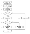
マイコンは、スイッチ25のオン操作を検出すると、まず、図5に示すように、ステップS1で、ヒータ22に対してフルパワーでフル通電を行う。その後、ステップS2で、前述のように、判断時間t1内に基準温度T1に達するか否かによって再保温制御の実行判断処理を実行した後、ステップS3で、再保温制御を実行させるか否かを意味するフラグfに1が入力(再保温制御を実行)されているか否を検出する。そして、fに0が入力されている場合、即ち、再保温制御を実行せずに抽出制御を実行する場合にはステップS4に進み、fに1が入力されている場合、即ち、再保温制御を実行する場合にはステップS8に進む。
When the microcomputer detects the on operation of the
ステップS4では、内蔵したタイマによって計測しながら、フルパワーでのフル通電を維持して飲料の抽出動作を行った後、抽出動作が完了したことを温度センサ23によって検出すると、ステップS5で、抽出制御に要した時間tが基準時間t2以上であるか否かを検出する。そして、t≧t2である場合にはステップS6に進み、温調温度が高い第1通常保温制御処理を実行する。また、t<t2である場合にはステップS7に進み、温調温度が低い第2通常保温制御処理を実行する。
In step S4, the
一方、ステップS3で、再保温制御を実行するように判断した場合にはステップS8で、温調温度が前記通常保温制御より更に低い再保温制御を実行する。 On the other hand, if it is determined in step S3 that re-warming control is to be executed, re-warming control in which the temperature control temperature is lower than the normal warming control is executed in step S8.
次に、ステップS2の再保温制御実行判断処理について具体的に説明する。なお、このステップS2では、再保温制御実行判断処理とは別に、空の飲料容器14をセットし、または、飲料容器14をセットすることなく、更に給水タンク16に水を入れることなくスイッチ25をオン操作した場合の空焚き判断処理が並行して実行される。
Next, the re-warming control execution determination process in step S2 will be specifically described. In this step S2, separately from the re-warming control execution determination process, the
この再保温制御実行判断処理では、マイコンは、図6に示すように、まず、ステップS10で、内蔵したタイマをスタートさせる。ついで、ステップS11で、温度センサ23によって温度Tを検出し、ステップS12で、その検出温度Tが基準温度T1より高いか否かを比較する。そして、T>T1である場合にはステップS13に進み、T≦T1である場合にはステップS15に進む。
In the re-warming control execution determination process, the microcomputer first starts a built-in timer in step S10 as shown in FIG. Next, in step S11, the temperature T is detected by the
ステップS13では、再保温制御を実行させるためのフラグfに1を入力した後、ステップS14で、タイマをリセットしてリターンする。 In step S13, 1 is input to the flag f for executing the re-warming control, and in step S14, the timer is reset and the process returns.
一方、ステップS15では、計測した経過時間tが判断時間t1を越えたか否かを検出する。そして、経過時間tが判断時間t1を越えた(t>t1)場合には、ステップS16に進み、抽出制御を実行させるためにフラグfに0を入力してステップS14に進み、タイマをリセットしてリターンする。また、経過時間tが判断時間t1を越えていない(t≦t1)場合にはステップS11に戻る。 On the other hand, in step S15, it is detected whether or not the measured elapsed time t has exceeded the determination time t1. If the elapsed time t exceeds the determination time t1 (t> t1), the process proceeds to step S16, and 0 is input to the flag f to execute the extraction control, and the process proceeds to step S14 to reset the timer. And return. If the elapsed time t does not exceed the determination time t1 (t ≦ t1), the process returns to step S11.
なお、ステップS6,7,8の第1,第2の通常保温制御および再保温制御は、スイッチ25がオフ操作されるまで、保温制御が実行され続け、スイッチ25がオフ操作されることによりヒータ22への通電を停止して制御を終了する。
Note that the first and second normal warming control and re-warming control in steps S6, S7, and S8 continue to be performed until the
このように、本実施形態の飲料抽出器では、抽出した飲料を再び保温する場合、飲料容器14内の飲料の容量が少なくなっていることが多いが、本実施形態では、判断時間t1のみフルパワーでフル通電した後に、温調温度が低い再保温専用の制御を実行するため、煮詰まりの問題を確実に防止できる。また、この再保温制御は、抽出制御を実行するための同一のスイッチ25を操作するだけで、自動的にいずれの制御を実行するかを判断して行うため、利便性の向上を図ることができる。
Thus, in the beverage extractor of the present embodiment, when the extracted beverage is kept warm again, the volume of the beverage in the
また、本実施形態では、抽出制御に要した時間tに基づいて続いて実行する通常保温制御の温調温度を変更する構成としているため、少ない抽出量であった場合の煮詰まりを防止できるうえ、多い抽出量であった場合の保温不足の問題を防止できる。 Moreover, in this embodiment, since it is set as the structure which changes the temperature control temperature of the normal heat retention control performed continuously based on the time t required for extraction control, it can prevent the clogging when it is a small extraction amount, The problem of insufficient heat retention when the amount of extraction is large can be prevented.
図7および図8は第2実施形態の飲料抽出器の制御を示す。この第2実施形態では、抽出制御の完了後に、ヒータ22が冷めていない状態で更に抽出制御を連続して行う場合、および、通常保温制御を一旦停止した後に再び保温する場合をも確実に抽出制御および再保温制御を実行できるように構成したものである。
7 and 8 show the control of the beverage extractor of the second embodiment. In the second embodiment, after the extraction control is completed, the extraction is performed reliably even when the extraction control is continuously performed in a state where the
なお、図1,2に示す飲料抽出器の各構成部品の構成、図3(A),(B)に示すヒータ22が冷めた状態での抽出制御および再保温制御の構成、および、図4に示す抽出制御に続いて実行する第1,第2の通常保温制御は、第1実施形態と同一である。
In addition, the structure of each component of the beverage extractor shown in FIGS. 1 and 2, the structure of the extraction control and the re-warming control in the state where the
第2実施形態のマイコンは、図7(A),(B)に示すように、前記スイッチ25が操作されると、予め設定された判断時間t1内に温度センサ23によって検出した温度Tが基準温度T1を越えるか否かによって、抽出制御および再保温制御のいずれを実行するかを判断するが、判断時間t1内の更に設定時間t1’内は除くように構成している。言い換えれば、第2実施形態では、スイッチ25のオン操作の後、t1’≦t≦t1の範囲内において検出温度Tが基準温度T1を越えた場合には再保温制御を実行するように構成している。また、経過時間tが設定時間t1’未満である場合に基準温度T1を超えており、この設定時間t1’を越えても基準温度T1を下回らない場合には、空焚きなどの異常と判断し、動作を停止するように構成している。
As shown in FIGS. 7A and 7B, in the microcomputer of the second embodiment, when the
ここで、図7(A)に示すように、ヒータ22が冷めていない状態において、ユーザが給水タンク16に水を入れてスイッチ25をオン操作することによる連続的なドリップ操作を行った場合には、温度センサ23によって検出する温度は、給水パイプ21への通水により徐々に下降して設定時間t1’を経過した時点では基準温度T1を下回り、再び徐々に上昇して判断時間t1を経過した後に基準温度T1に達する。また、図7(B)に示すように、ヒータ22が冷めていない状態において、ユーザがスイッチ25をオフ操作して再びオン操作した場合には、温度センサ23によって検出する温度は、ヒータ22より温度が低い飲料により若干下降し続けて設定時間t1’を経過した時点では基準温度T1を下回り、飲料の昇温とともに再び徐々に上昇して判断時間t1を経過する前に基準温度T1に達する。そのため、t1’≦t≦t1の範囲内において検出温度Tが基準温度T1を越えるか否かにより、連続ドリップ操作か再保温操作かを判断することができる。
Here, as shown in FIG. 7A, when the user performs a continuous drip operation by putting water into the
次に、第2実施形態のマイコンによる再保温制御実行判断処理について具体的に説明する。 Next, the re-warming control execution determination process by the microcomputer of the second embodiment will be specifically described.
この再保温制御実行判断処理では、マイコンは、図8に示すように、まず、ステップS20で、内蔵したタイマをスタートさせる。ついで、ステップS21で、温度センサ23によって温度Tを検出し、ステップS22で、その検出温度Tが基準温度T1より高いか否かを比較する。そして、T>T1である場合にはステップS23に進み、T≦T1である場合にはステップS27に進む。
In this re-warming control execution determination process, as shown in FIG. 8, the microcomputer first starts a built-in timer in step S20. Next, in step S21, the temperature T is detected by the
ステップS23では、経過時間tが設定時間t1’を越えるまで待機する。そして、経過時間tが設定時間t1’を越えると、ステップS24で、再び温度Tを検出し、ステップS25で、その検出温度Tが基準温度T1より高いか否かを比較する。そして、T>T1である場合には異常であると判断してステップS26に進み、停止処理を実行して動作を終了する。また、T≦T1である場合にはステップS27に進む。 In step S23, the process waits until the elapsed time t exceeds the set time t1 '. When the elapsed time t exceeds the set time t1 ', the temperature T is detected again in step S24, and whether or not the detected temperature T is higher than the reference temperature T1 is compared in step S25. If T> T1, it is determined that there is an abnormality, the process proceeds to step S26, a stop process is executed, and the operation is terminated. If T ≦ T1, the process proceeds to step S27.
ステップS27では、温度センサ23によって温度Tを検出し、ステップS28で、その検出温度Tが基準温度T1より高いか否かを比較する。そして、T>T1である場合にはステップS29に進み、T≦T1である場合にはステップS31に進む。
In step S27, the temperature T is detected by the
ステップS29では、再保温制御を実行させるためのフラグfに1を入力した後、ステップS30で、タイマをリセットしてリターンする。 In step S29, 1 is input to the flag f for executing the re-warming control, and in step S30, the timer is reset and the process returns.
一方、ステップS31では、計測した経過時間tが判断時間t1を越えたか否かを検出する。そして、経過時間tが判断時間t1を越えた(t>t1)場合には、ステップS32に進み、抽出制御を実行させるためにフラグfに0を入力してステップS30に進み、タイマをリセットしてリターンする。また、経過時間tが判断時間t1を越えていない(t≦t1)場合にはステップS27に戻る。 On the other hand, in step S31, it is detected whether or not the measured elapsed time t has exceeded the determination time t1. If the elapsed time t exceeds the determination time t1 (t> t1), the process proceeds to step S32, and 0 is input to the flag f to execute the extraction control, the process proceeds to step S30, and the timer is reset. And return. If the elapsed time t does not exceed the determination time t1 (t ≦ t1), the process returns to step S27.
この第2実施形態の飲料抽出器では、第1実施形態と同様の作用および効果を得ることができるうえ、ヒータ22が冷めていない状態であっても確実にユーザの目的に応じた制御を自動的に実行させることができるため、より利便性を向上できる。
In the beverage extractor according to the second embodiment, the same operation and effect as the first embodiment can be obtained, and control according to the user's purpose is automatically performed even when the
なお、本発明の飲料抽出器は、前記実施形態の構成に限定されるものではなく、種々の変更が可能である。 In addition, the drink extractor of this invention is not limited to the structure of the said embodiment, A various change is possible.
例えば、前記各実施形態では、判断時間t1内において、温度センサ23によって繰り返し温度Tを検出したが、判断時間t1が経過した時点の1回のみ検出する構成としてもよい。
For example, in each of the embodiments, the temperature T is repeatedly detected by the
また、通常保温制御は、温調温度が異なる2種の保温制御としたが、3以上異なる温調温度で保温制御するように構成してもよい。 In addition, the normal temperature control is two types of temperature control with different temperature control temperatures, but the temperature control may be performed at three or more different temperature control temperatures.
10…本体、11…ノーズ、12…給水部材、13…ベース、14…飲料容器、15…金属板、16…給水タンク、17…蓋、18…バケット、19…カバー、20…止水機構、21…給水パイプ、22…ヒータ(加熱手段)、23…温度センサ(温度検出手段)、24…固定部材、25…スイッチ。
DESCRIPTION OF
Claims (2)
前記制御手段は、前記通常保温制御とは別に、前記抽出制御を実行することなく前記飲料容器を保温するとともに、前記通常保温制御での通電率より低い通電率で前記加熱手段に通電する再保温制御を実行する構成としており、
前記スイッチのオン操作または前記加熱手段による加熱開始後の予め設定した判断時間内に前記温度検出手段によって検出した温度に基づいて、前記抽出制御を実行するか再保温制御を実行するかを判断し、前記判断時間内に予め設定した基準温度を越えた場合には前記再保温制御を実行し、判断時間内に基準温度を越えない場合には前記抽出制御を実行するようにしたことを特徴とする飲料抽出器。 A water supply tank for receiving water, a bucket for storing beverage extraction raw materials, a base for detachably installing a beverage container positioned at the lower portion of the bucket and receiving a beverage to flow out, and the bucket from the water supply tank through the lower portion of the base A water supply pipe piped above, heating means for heating the water in the pipe in the base and heating the beverage container installed in the base, temperature detecting means for detecting the temperature of the beverage container, A switch for executing the beverage extraction by the heating means, and a control means for controlling the heating means by the operation of the switch to execute the beverage extraction control, and subsequently executing the normal heat retention control of the beverage container; In a beverage extractor comprising
In addition to the normal heat retention control , the control means keeps the beverage container warm without executing the extraction control, and reheats the current by energizing the heating means at an energization rate lower than the energization rate in the normal heat insulation control. It is configured to execute control ,
It is determined whether to perform the extraction control or the re-warming control based on the temperature detected by the temperature detection means within a preset determination time after the switch is turned on or the heating means starts heating. The re-warming control is executed when a preset reference temperature is exceeded within the determination time, and the extraction control is executed when the reference temperature is not exceeded within the determination time. Beverage extractor.
前記制御手段は、抽出制御の開始後に、抽出が完了したことを示す予め設定した温度に至るまでに要した時間に基づいて予め設定された温調温度で保温制御を実行するようにしたことを特徴とする請求項1に記載の飲料抽出器。 In the normal heat retention control executed after the extraction control, two or more different temperature control temperatures are set,
The control means is configured to perform the heat retention control at a preset temperature control temperature based on a time required to reach a preset temperature indicating that the extraction is completed after the start of the extraction control. The beverage extractor according to claim 1, wherein
Priority Applications (1)
| Application Number | Priority Date | Filing Date | Title |
|---|---|---|---|
| JP2004067483A JP4035112B2 (en) | 2004-03-10 | 2004-03-10 | Beverage extractor |
Applications Claiming Priority (1)
| Application Number | Priority Date | Filing Date | Title |
|---|---|---|---|
| JP2004067483A JP4035112B2 (en) | 2004-03-10 | 2004-03-10 | Beverage extractor |
Publications (2)
| Publication Number | Publication Date |
|---|---|
| JP2005253593A JP2005253593A (en) | 2005-09-22 |
| JP4035112B2 true JP4035112B2 (en) | 2008-01-16 |
Family
ID=35079917
Family Applications (1)
| Application Number | Title | Priority Date | Filing Date |
|---|---|---|---|
| JP2004067483A Expired - Fee Related JP4035112B2 (en) | 2004-03-10 | 2004-03-10 | Beverage extractor |
Country Status (1)
| Country | Link |
|---|---|
| JP (1) | JP4035112B2 (en) |
Families Citing this family (1)
| Publication number | Priority date | Publication date | Assignee | Title |
|---|---|---|---|---|
| JP2007301293A (en) * | 2006-05-15 | 2007-11-22 | Zojirushi Corp | Beverage extracting machine |
-
2004
- 2004-03-10 JP JP2004067483A patent/JP4035112B2/en not_active Expired - Fee Related
Also Published As
| Publication number | Publication date |
|---|---|
| JP2005253593A (en) | 2005-09-22 |
Similar Documents
| Publication | Publication Date | Title |
|---|---|---|
| RU2565657C2 (en) | Fast heating of thermal treatment device, for example, for coffee machine | |
| RU2468730C2 (en) | Method and device for cooking food, such as rice | |
| JP3867637B2 (en) | Steam generating device and cooking device provided with steam generating device | |
| CN106163351A (en) | Carry out the method for cooking process based on liquid, controller and cooking stove assembly | |
| US20040159240A1 (en) | Beverage brewing apparatus and method | |
| JP2013531526A5 (en) | ||
| JP4035112B2 (en) | Beverage extractor | |
| US20090293734A1 (en) | Beverage maker having a thermostat for controlling the operation of heating means for heating water | |
| JP2011224167A (en) | Electric rice cooker | |
| JP2007044327A (en) | Electric hot-water storage vessel | |
| JP4036180B2 (en) | Electric water heater | |
| JP2013075095A (en) | Rice cooker | |
| JP5408118B2 (en) | rice cooker | |
| JP2005348990A (en) | Rice cooker | |
| JP2008178507A (en) | Beverage dispenser | |
| JP2013034890A (en) | Electric pot | |
| JP5176580B2 (en) | an electronic pot | |
| JP2007097936A (en) | Electric kettle | |
| JP3876868B2 (en) | rice cooker | |
| JP2023137410A (en) | liquid heater | |
| JP4260143B2 (en) | Electric pot | |
| JP5272931B2 (en) | Electric water heater | |
| JP3876869B2 (en) | rice cooker | |
| JP2008228985A (en) | Electric hot water reserving container | |
| JP2024141225A (en) | Liquid Heater |
Legal Events
| Date | Code | Title | Description |
|---|---|---|---|
| A621 | Written request for application examination |
Free format text: JAPANESE INTERMEDIATE CODE: A621 Effective date: 20051108 |
|
| A977 | Report on retrieval |
Free format text: JAPANESE INTERMEDIATE CODE: A971007 Effective date: 20070622 |
|
| A131 | Notification of reasons for refusal |
Free format text: JAPANESE INTERMEDIATE CODE: A131 Effective date: 20070703 |
|
| A521 | Written amendment |
Free format text: JAPANESE INTERMEDIATE CODE: A523 Effective date: 20070817 |
|
| TRDD | Decision of grant or rejection written | ||
| A01 | Written decision to grant a patent or to grant a registration (utility model) |
Free format text: JAPANESE INTERMEDIATE CODE: A01 Effective date: 20071023 |
|
| A61 | First payment of annual fees (during grant procedure) |
Free format text: JAPANESE INTERMEDIATE CODE: A61 Effective date: 20071026 |
|
| FPAY | Renewal fee payment (event date is renewal date of database) |
Free format text: PAYMENT UNTIL: 20101102 Year of fee payment: 3 |
|
| R150 | Certificate of patent or registration of utility model |
Ref document number: 4035112 Country of ref document: JP Free format text: JAPANESE INTERMEDIATE CODE: R150 Free format text: JAPANESE INTERMEDIATE CODE: R150 |
|
| FPAY | Renewal fee payment (event date is renewal date of database) |
Free format text: PAYMENT UNTIL: 20101102 Year of fee payment: 3 |
|
| FPAY | Renewal fee payment (event date is renewal date of database) |
Free format text: PAYMENT UNTIL: 20131102 Year of fee payment: 6 |
|
| R250 | Receipt of annual fees |
Free format text: JAPANESE INTERMEDIATE CODE: R250 |
|
| R250 | Receipt of annual fees |
Free format text: JAPANESE INTERMEDIATE CODE: R250 |
|
| R250 | Receipt of annual fees |
Free format text: JAPANESE INTERMEDIATE CODE: R250 |
|
| LAPS | Cancellation because of no payment of annual fees |