JP4034603B2 - Digital camera - Google Patents
Digital camera Download PDFInfo
- Publication number
- JP4034603B2 JP4034603B2 JP2002176222A JP2002176222A JP4034603B2 JP 4034603 B2 JP4034603 B2 JP 4034603B2 JP 2002176222 A JP2002176222 A JP 2002176222A JP 2002176222 A JP2002176222 A JP 2002176222A JP 4034603 B2 JP4034603 B2 JP 4034603B2
- Authority
- JP
- Japan
- Prior art keywords
- digital camera
- subject image
- power saving
- power
- saving mode
- Prior art date
- Legal status (The legal status is an assumption and is not a legal conclusion. Google has not performed a legal analysis and makes no representation as to the accuracy of the status listed.)
- Expired - Fee Related
Links
Images


Landscapes
- Camera Bodies And Camera Details Or Accessories (AREA)
- Studio Devices (AREA)
Description
【0001】
【発明の属する技術分野】
本発明は、デジタルカメラに係り、特に、デジタルカメラの省電力化に関する。
【0002】
【従来の技術】
近年、CCD(Charge Coupled Device)、CMOS(Complementary Metal Oxide Semiconductor)イメージ・センサ等の撮像素子の高解像度化に伴い、デジタルカメラの需要が急増している。
【0003】
ところで、この種のデジタルカメラで使用される電気部品は、上記撮像素子、高速のCPU(中央演算処理装置)、液晶ディスプレイ(以下、「LCD」という。)、当該LCDのバックライト等、消費電力の大きなものが多い。その一方で、この種のデジタルカメラは、携帯してのモバイル環境における使用が前提とされており、筐体の大きさと重量から、大きな電池や多数本の電池を使用することはできない。このため、電池の容量に比較して消費電力が大きいため、使用時間の短い機種が多い。
【0004】
この点に鑑み、特開2000−59675に記載の技術では、録画モードや再生モード等の動作モードを選択するスイッチと、電源スイッチと、レリーズスイッチの操作状況から装置の動作状態を判定し、装置の動作状態の継続時間がそれぞれの動作状態に応じた所定時間を越えたことを判定したときに省電力モードに移行するようにしていた。
【0005】
【発明が解決しようとする課題】
しかしながら、上記特開2000−59675に記載の技術では、各種スイッチ類が操作されない状態が所定時間を越えて継続したときには無条件に省電力モードに移行するので、例えば、撮影シーンを決定しようとしてデジタルカメラの向きを変えているとき等の継続的なスイッチ類の操作が行われないときにも省電力モードに移行してしまう、という問題点があった。この場合、撮影のために省電力モードを解除する必要が生じ、ユーザにとっての利便性が著しく損なわれることになる。
【0006】
また、電源スイッチを切らないままデジタルカメラをポケット、鞄、収納ケース等に収納した場合には、できるだけ早く省電力モードに移行させたいが、上記特開2000−59675に記載の技術では、このような場合であっても所定時間が経過するまで省電力モードに移行しない、という問題点もあった。この問題点を解消するためには、上記所定時間を短く定めればよいが、この場合には、撮影シーンを決定しようとしてデジタルカメラの向きを変えているとき等の省電力モードに移行して欲しくないときにも省電力モードに移行しやすくなってしまう、という新たな問題点が発生する。
【0007】
本発明は上記問題点を解消するためになされたものであり、的確なタイミングで省電力モードに移行することのできるデジタルカメラを提供することを目的とする。
【0008】
【課題を解決するための手段】
上記目的を達成するために、請求項1記載のデジタルカメラは、被写体を撮像して被写体像を示す画像情報を得る撮像手段と、前記撮像手段により得られた前記画像情報に基づいて前記被写体像に動きがあったか否かを判断する判断手段と、前記判断手段により前記被写体像に所定時間以上動きがなかったと判断されたときに消費電力を低減させる省電力モードに移行させる移行手段と、各種操作を行うために操作される操作手段と、を備え、前記移行手段が、当該移行手段による前記省電力モードへの移行を行わない状態で前記操作手段に対する操作が前記所定時間より長い第2の時間以上行われなかったときに前記省電力モードに移行させるものである。
【0009】
請求項1に記載のデジタルカメラによれば、撮像手段によって被写体が撮像されて被写体像を示す画像情報が得られ、当該画像情報に基づいて被写体像に動きがあったか否かが判断手段により判断される。なお、上記撮像手段には、CCD、CMOSイメージ・センサ等の固体撮像素子が含まれる。
【0010】
ここで、請求項1に記載の発明では、上記判断手段により被写体像に所定時間以上動きがなかったと判断されたときに、消費電力を低減させる省電力モードに移行手段によって移行される。
【0011】
すなわち、デジタルカメラに設けられたスイッチ類に対する操作が行われない状態が継続した場合であっても、省電力モードに移行させたくない状態として、撮影対象とする被写体をファインダ内に収めたり、ファインダ内に収まった被写体の構図を決定する等のためにデジタルカメラの撮影方向を変更している状態が殆どを占める。そして、この状態のときには、デジタルカメラの撮影方向が変更されているので、殆どの場合は撮像により得られた画像情報によって示される被写体像に動きがある状態となる。
【0012】
本発明では、この点に着目し、上記被写体像に所定時間以上動きがなかったと判断されたときに省電力モードに移行させるようにしており、これによってデジタルカメラに設けられたスイッチ類に対する操作が行われない状態が継続した場合に省電力モードに移行させる従来技術より的確なタイミングで省電力モードに移行させることができるようにしている。
【0013】
また、本発明は、被写体像に動きがなかった場合に省電力モードに移行させるものであるので、電源スイッチを切らないままデジタルカメラをポケット、鞄、収納ケース等に収納した場合においても、この場合は被写体像に動きがない状態となるので、速やかに省電力モードに移行させることができる。
【0014】
このように、請求項1に記載のデジタルカメラによれば、撮像によって得られた画像情報により示される被写体像に所定時間以上動きがなかったと判断されたときに省電力モードに移行させているので、的確なタイミングで省電力モードに移行することができる。
【0016】
また、請求項1に記載のデジタルカメラによれば、各種操作を行うために操作手段が操作される。なお、当該操作手段には、撮影を行う際に操作されるレリーズスイッチ、動作モードを設定する際に操作されるモード切替スイッチ、被写体像の拡大ないし縮小を行う際に操作されるズームボタン等の、デジタルカメラに設けられている全てのスイッチ類、ボタン類が含まれる。
【0017】
ここで、請求項1に記載の発明では、移行手段により、当該移行手段による省電力モードへの移行を行わない状態で操作手段に対する操作が上記所定時間より長い第2の時間以上行われなかったときに省電力モードに移行される。
【0018】
すなわち、本発明では、画像情報によって示される被写体像に継続的に動きがある場合であっても、操作手段に対する操作が継続的に行われない場合には、撮影を行う意志がないものと見なして省電力モードに移行するようにしており、これによって、より的確なタイミングで省電力モードに移行させることができるようにしている。
【0019】
このように、請求項1に記載のデジタルカメラによれば、省電力モードへの移行が行われない状態で操作手段に対する操作が本発明の所定時間より長い第2の時間以上行われなかったときに省電力モードに移行させているので、より的確なタイミングで省電力モードに移行することができる。
【0020】
更に、請求項2記載のデジタルカメラは、請求項1記載の発明において、前記移行手段により前記省電力モードに移行された後、前記判断手段により前記被写体像に予め定めた第3の時間以上動きがなかったと判断されたときに電源オフの状態とする電源オフ手段を更に備えたものである。
【0021】
請求項2に記載のデジタルカメラによれば、本発明の移行手段により省電力モードに移行された後、本発明の判断手段により被写体像に予め定めた第3の時間以上動きがなかったと判断されたときに、電源オフ手段によって電源オフの状態とされる。
【0022】
すなわち、本発明では、省電力モードに移行された後も、撮像により得られた画像情報によって示される被写体像に継続的に動きがない場合には、暫くは撮影が行われることがないものと見なして電源オフの状態としており、これによって省電力効果を大幅に向上できるようにしている。
【0023】
このように、請求項2に記載のデジタルカメラによれば、請求項1記載の発明と同様の効果を奏することができると共に、省電力モードに移行された後、被写体像に予め定めた第3の時間以上動きがなかったと判断されたときに電源オフの状態としているので、省電力効果を大幅に向上させることができる。
【0024】
なお、上記請求項2記載の発明の好適な態様(以下、「第1態様」という。)として、前記移行手段により前記省電力モードに移行された後で、かつ前記電源オフ手段により電源オフの状態とされる前に前記判断手段により前記被写体像に動きがあったと判断されたときに前記省電力モードを解除する解除手段を更に備える態様を挙げることができる。
【0025】
本第1態様に係るデジタルカメラによれば、移行手段により省電力モードに移行された後で、かつ電源オフ手段により電源オフの状態とされる前に、判断手段により被写体像に動きがあったと判断されたときに上記省電力モードが解除手段によって解除される。
【0026】
このように、本第1態様に係るデジタルカメラによれば、請求項2記載の発明と同様の効果を奏することができると共に、省電力モードに移行された後で、かつ電源オフの状態とされる前に、被写体像に動きがあったと判断されたときに上記省電力モードを解除しているので、省電力モードに移行した後の通常のモードへの復帰の手間を無くすることができ、ユーザにとっての利便性を向上させることができる。
【0027】
また、本発明の好適な態様(以下、「第2態様」という。)として、前記画像情報により示される前記被写体像の全体的な明るさが所定レベル以下である場合、他の場合より前記所定時間を短いものとする態様を挙げることができる。
【0028】
すなわち、電源スイッチを切らないままデジタルカメラをポケット、鞄、収納ケース等に収納した場合には、撮像により得られた画像情報によって示される被写体像は一様に暗い画像となる。
【0029】
この点に着目し、本第2態様に係るデジタルカメラでは、上記画像情報により示される被写体像の全体的な明るさが所定レベル以下である場合には、デジタルカメラが収納されたものと見なして他の場合より上記所定時間を短いものとしており、これによって、デジタルカメラが収納された場合の省電力モードへの移行のタイミングを他の場合より早して、省電力効果を向上できるようにしている。
【0030】
このように、本第2態様に係るデジタルカメラによれば、請求項1又は請求項2記載の発明と同様の効果を奏することができると共に、画像情報により示される被写体像の全体的な明るさが所定レベル以下である場合、他の場合より本発明の所定時間を短いものとしているので、省電力効果をより向上させることができる。
【0031】
また、本発明の好適な態様(以下、「第3態様」という。)として、前記判断手段は、前記画像情報の変化量に基づいて前記被写体像に動きがあったか否かを判断する態様を挙げることができる。
【0032】
本第3態様に係るデジタルカメラによれば、判断手段により、上記画像情報の変化量に基づいて被写体像に動きがあったか否かが判断される。より具体的には、上記画像情報の変化量が所定量以上である場合には被写体像に動きがあったものとし、他の場合には被写体像に動きがなかったものとする。
【0033】
このように、本第3態様に係るデジタルカメラによれば、請求項1又は請求項2記載の発明と同様の効果を奏することができると共に、画像情報の変化量に基づいて被写体像に動きがあったか否かを判断しているので、被写体像に動きがあったか否かの判断にマージンを設けることができ、柔軟性の高い判断を行うことができる。
【0034】
更に、本第3態様に係る発明の好適な態様(以下、「第4態様」という。)として、前記判断手段は、前記画像情報に基づいて得られる前記被写体像の複数の分割領域における測光レベルの変化量に基づいて前記被写体像に動きがあったか否かを判断する態様を挙げることができる。
【0035】
本第4態様に係るデジタルカメラによれば、判断手段により、画像情報に基づいて得られる被写体像の複数の分割領域における測光レベルの変化量に基づいて被写体像に動きがあったか否かが判断される。
【0036】
すなわち、現在のデジタルカメラには、自動露出機能を実現するために、画像情報に基づいて被写体像の複数の分割領域における測光レベルを検出しているものが多い。この点に着目し、本第4態様に係るデジタルカメラでは、当該測光レベルを画像情報に基づく情報として利用して、当該測光レベルの変化量に基づいて被写体像の動きの有無を判断するようにしており、これによって、画像情報そのものを用いて判断する場合に比較して、短時間に判断できるようにしている。
【0037】
このように、本第4態様に係るデジタルカメラによれば、上記第3態様に係る発明と同様の効果を奏することができると共に、画像情報に基づいて得られる被写体像の複数の分割領域における測光レベルの変化量に基づいて被写体像に動きがあったか否かを判断しているので、当該判断を短時間に行うことができる。
【0038】
【発明の実施の形態】
以下、図面を参照して、本発明の実施の形態について詳細に説明する。
【0039】
〔第1実施形態〕
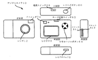
まず、図1を参照して、本実施の形態に係るデジタルカメラ10の外観上の構成を説明する。同図に示すように、デジタルカメラ10の正面には、被写体像を結像させるためのレンズ12と、撮影する被写体の構図を決定するために用いられるファインダ70と、が備えられている。また、デジタルカメラ10の上面には、撮影を実行する際に撮影者によって押圧操作されるレリーズボタン(所謂シャッター)60と、電源スイッチ66と、が備えられている。
【0040】
なお、本実施の形態に係るレリーズボタン60は、中間位置まで押下される状態(以下、「半押し状態」という。)と、当該中間位置を超えた最終押下位置まで押下される状態(以下、「全押し状態」という。)と、の2段階の押圧操作が検出可能に構成されている。そして、本実施の形態に係るデジタルカメラ10では、レリーズボタン60を半押し状態にすることによりAE(Automatic Exposure、自動露出)機能が働いて露出状態(シャッタースピード、絞りの状態)が設定された後、AF(Auto Focus、自動合焦)機能が働いて合焦制御され、その後、引き続き全押し状態にすると露光(撮影)が行われる。
【0041】
一方、デジタルカメラ10の背面には、前述のファインダ70の接眼部と、撮影によって得られたデジタル画像データにより示される被写体像や各種メニュー画面、メッセージ等を表示するための液晶ディスプレイ(以下、「LCD」という。)30と、撮影を行うモードである撮影モード及び撮影によって得られたデジタル画像データにより示される被写体像をLCD30に表示(再生)するモードである再生モードの何れかのモードに設定するために操作されるモード切替スイッチ62と、LCD30の表示領域における上下左右の4方向の移動方向を示す4つの矢印キー及び当該4つの矢印キーの中央部に位置された決定キーの合計5つのキーを含んで構成された十字カーソルボタン64と、が備えられている。
【0042】
一方、デジタルカメラ10の側面には、撮影によって得られたデジタル画像データが記録可能な記録メディア(ここでは、当該デジタル画像データが画像ファイルとして記録される記録メディア。)を装着することができるスロットSL1及びスロットSL2が設けられており、デジタルカメラ10の底面には、外部装置と所定のインタフェース規格(本実施の形態では、USB(Universal Serial Bus))により電気的に接続するために用いられるレセプタクル72が設けられている。
【0043】
次に、図2を参照して、本実施の形態に係るデジタルカメラ10の電気系の構成を説明する。
【0044】
同図に示すように、デジタルカメラ10は、前述のレンズ12を含んで構成された光学ユニット13と、レンズ12の光軸後方に配設されたCCD14と、相関二重サンプリング回路(以下、「CDS」という。)16と、入力されたアナログ信号をデジタルデータに変換するアナログ/デジタル変換器(以下、「ADC」という。)18と、を含んで構成されており、CCD14の出力端はCDS16の入力端に、CDS16の出力端はADC18の入力端に、各々接続されている。
【0045】
ここで、CDS16による相関二重サンプリング処理は、固体撮像素子の出力信号に含まれるノイズ(特に熱雑音)等を軽減することを目的として、固体撮像素子の1画素毎の出力信号に含まれるフィードスルー成分レベルと画素信号成分レベルとの差をとることにより正確な画素データを得る処理である。
【0046】
一方、デジタルカメラ10は、所定容量のラインバッファを内蔵すると共に入力されたデジタル画像データを後述する第2メモリ40の所定領域に直接記憶させる制御を行う画像入力コントローラ20と、デジタル画像データに対して各種画像処理を施す画像信号処理回路22と、所定の圧縮形式でデジタル画像データに対して圧縮処理を施す一方、圧縮処理されたデジタル画像データに対して圧縮形式に応じた形式で伸張処理を施す圧縮・伸張処理回路24と、デジタル画像データにより示される画像やメニュー画面等をLCD30に表示させるための信号を生成してLCD30に供給する一方、LCD30に表示させる画像を示す映像信号(本実施の形態では、NTSC信号。)を生成してビデオ出力端子OUTに出力するビデオ/LCDエンコーダ28と、を含んで構成されている。なお、画像入力コントローラ20の入力端はADC18の出力端に接続されている。
【0047】
また、デジタルカメラ10は、デジタルカメラ10全体の動作を司るCPU32と、AF機能を働かせるために必要とされる物理量(本実施の形態では、CCD14による撮像によって得られた画像のコントラスト値。)を検出するAF検出回路34と、AE機能及びAWB(Automatic White Balance)機能を働かせるために必要とされる物理量(本実施の形態では、CCD14による撮像によって得られた画像の明るさを示す量(以下、「測光データ」という。)。)を検出するAE・AWB検出回路36と、CPU32による各種処理の実行時のワークエリア等として用いられるSDRAM(Synchronous Dynamic Random Access Memory)により構成された第1メモリ38と、主として撮影により得られたデジタル画像データを記憶するVRAM(Video RAM)により構成された第2メモリ40と、を含んで構成されている。
【0048】
更に、デジタルカメラ10は、スロットSL1に装着された記録メディア42A及びスロットSL2に装着された記録メディア42Bをデジタルカメラ10でアクセス可能とするためのメディアコントローラ42と、前述のレセプタクル72に接続されると共にUSB規格による外部との間の通信を司るUSBインタフェース46と、を含んで構成されている。
【0049】
以上の画像入力コントローラ20、画像信号処理回路22、圧縮・伸張処理回路24、ビデオ/LCDエンコーダ28、CPU32、AF検出回路34、AE・AWB検出回路36、第1メモリ38、第2メモリ40、メディアコントローラ42、及びUSBインタフェース46は、各々システムバスBUSを介して相互に接続されている。
【0050】
従って、CPU32は、画像入力コントローラ20、画像信号処理回路22、圧縮・伸張処理回路24、及びビデオ/LCDエンコーダ28の各々の作動の制御と、AF検出回路34及びAE・AWB検出回路36により検出された物理量の取得と、第1メモリ38、第2メモリ40、記録メディア42A、及び記録メディア42Bへのアクセスと、レセプタクル72に接続された外部装置との相互通信と、を各々行うことができる。
【0051】
一方、デジタルカメラ10には、主としてCCD14を駆動させるためのタイミング信号を生成してCCD14に供給するタイミングジェネレータ48が設けられており、当該タイミングジェネレータ48の入力端はCPU32に、出力端はCCD14に、各々接続されており、CCD14の駆動は、CPU32によりタイミングジェネレータ48を介して制御される。
【0052】
更に、CPU32はモータ駆動部50の入力端に接続され、モータ駆動部50の出力端は光学ユニット13に備えられた焦点調整モータ、ズームモータ及び絞り駆動モータに接続されている。
【0053】
本実施の形態に係る光学ユニット13に含まれるレンズ12は複数枚のレンズを有し、焦点距離の変更(変倍)が可能なズームレンズとして構成されており、図示しないレンズ駆動機構を備えている。このレンズ駆動機構に上記焦点調整モータ、ズームモータ及び絞り駆動モータは含まれるものであり、焦点調整モータ、ズームモータ及び絞り駆動モータは各々CPU32の制御下でモータ駆動部50から供給された駆動信号によって駆動される。
【0054】
CPU32は、光学ズーム倍率を変更する際にはズームモータを駆動制御して光学ユニット13に含まれるレンズの焦点距離を変化させる。
【0055】
また、CPU32は、CCD14による撮像によって得られた画像のコントラスト値が最大となるように上記焦点調整モータを駆動制御することによって合焦制御を行う。すなわち、本実施の形態に係るデジタルカメラ10では、合焦制御として、読み取られた画像のコントラストが最大となるようにレンズの位置を設定する、所謂TTL(Through The Lens)方式を採用している。
【0056】
更に、前述のレリーズボタン60、モード切替スイッチ62、十字カーソルボタン64、及び電源スイッチ66の各種ボタン類及びスイッチ類(図2では、「操作部52」と総称。)はCPU32に接続されており、CPU32は、これらのボタン類及びスイッチ類に対する操作状態を常時把握できる。
【0057】
また、本実施の形態に係るデジタルカメラ10には、電源回路54と電池56が備えられており、電源回路54は、CPU32による制御の下に、電池56から出力された電力に基づいて適切な作動用の電力を生成して各部に供給する。なお、錯綜を回避するために、同図では、電源回路54から電力が供給される各部への接続線の図示を省略している。
【0058】
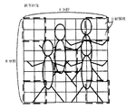
ところで、本実施の形態に係るAE・AWB検出回路36では、図3に示すように、CCD14による撮像等によって得られたデジタル画像データが示す被写体像を所定数×所定数(本実施の形態では、8×8)の分割領域に分割し、各分割領域毎に当該分割領域の平均的な明るさを示す測光データを逐次導出するように構成されている。従って、CPU32は、最新の各分割領域毎の測光データをAE・AWB検出回路36から任意に取得することができる。
【0059】
CCD14が本発明の撮像手段に、操作部52が本発明の操作手段に、CPU32が本発明の判断手段、移行手段、及び電源オフ手段に、各々相当する。また、CPU32が前述の第1態様における解除手段に相当する。
【0060】
次に、本実施の形態に係るデジタルカメラ10の作用を説明する。まず、撮影時におけるデジタルカメラ10の作用を簡単に説明する。
【0061】
光学ユニット13を介した撮像によってCCD14から出力された被写体像を示す信号は順次CDS16に入力されて相関二重サンプリング処理が施された後にADC18に入力され、ADC18は、CDS16から入力されたR(赤)、G(緑)、B(青)の信号を各々12ビットのR、G、B信号(デジタル画像データ)に変換して画像入力コントローラ20に出力する。
【0062】
画像入力コントローラ20は内蔵しているラインバッファにADC18から順次入力されるデジタル画像データを蓄積して一旦第2メモリ40の所定領域に格納する。
【0063】
第2メモリ40の所定領域に格納されたデジタル画像データは、CPU32による制御下で画像信号処理回路22によって読み出され、これらにAE・AWB検出回路36により検出された物理量(測光データ)に応じたデジタルゲインをかけることでホワイトバランス調整を行うと共に、ガンマ処理及びシャープネス処理を行なって8ビットのデジタル画像データを生成し、更にYC信号処理を施して輝度信号Yとクロマ信号Cr、Cb(以下、「YC信号」という。)を生成し、YC信号を第2メモリ40の上記所定領域とは異なる領域に格納する。
【0064】
なお、LCD30は、CCD14による連続的な撮像によって得られた動画像(スルー画像)を表示してファインダとして使用することができるものとして構成されているが、このようにLCD30をファインダとして使用する場合には、生成したYC信号を、ビデオ/LCDエンコーダ28を介して順次LCD30に出力する。これによってLCD30にスルー画像が表示されることになる。
【0065】
ここで、レリーズボタン60がユーザによって全押し状態とされたときには、その時点で第2メモリ40に格納されているYC信号を、圧縮・伸張処理回路24によって所定の圧縮形式(本実施の形態では、JPEG形式)で圧縮した後にメディアコントローラ42を介して記録メディア42Aに記録する。
【0066】
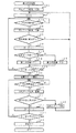
次に、図4を参照して、デジタルカメラ10において実行される電力切替処理について説明する。なお、図4は、電源スイッチ66がオン状態とされているときにデジタルカメラ10のCPU32で実行される電力切替処理プログラムの処理の流れを示すフローチャートである。
【0067】
同図のステップ100では、AE・AWB検出回路36から所定の分割領域における測光データを取得して第1メモリ38の所定領域に記憶し、次のステップ102では、変数Nに0(零)を代入する。なお、上記所定の分割領域として、本実施の形態では、被写体像の中心部に位置する4つの分割領域と、被写体像の四隅に各々位置する4つの分割領域の合計20の分割領域(図3の破線で囲まれた分割領域)の測光データを適用する。これによって、被写体像の中心部に動きがなく、かつ被写体像の周辺部に動きがある場合と、被写体像の周辺部に動きがなく、かつ被写体像の中心部に動きがある場合と、の双方の場合に対応できるようにしている。
【0068】
次のステップ104では、CPU32に内蔵された不図示のタイマを用いて所定時間(本実施の形態では、3秒)の経過待ちを行い、次のステップ106では、再びAE・AWB検出回路36から上記所定の分割領域における測光データを取得して第1メモリ38の他の領域に記憶する。
【0069】
次のステップ108では、上記ステップ100及びステップ106において第1メモリ38に記憶した測光データに基づいて被写体像に動きがあったか否かを判定し、肯定判定の場合は上記ステップ102に戻り、否定判定の場合にはステップ110に移行する。
【0070】
なお、本実施の形態に係るデジタルカメラ10では、上記ステップ108における被写体像に動きがあったか否かの判定を、上記ステップ106において記憶した測光データと、上記ステップ100において記憶した測光データとを対応する分割領域毎に各々比較し、測光データが所定値(本実施の形態では、上記ステップ100において記憶した当該分割領域の測光データの10%に相当する値)以上変化した分割領域数が所定数(本実施の形態では、適用した分割領域数の2分の1に相当する10)以上存在するか否かを判定することによって行う。また、上記ステップ102〜ステップ108の処理を繰り返して実行する場合に上記ステップ108では、直前のステップ106の処理によって記憶した測光データと、その前回のステップ106の処理によって記憶した測光データと、に基づいて被写体像に動きがあったか否かを判定する。
【0071】
ステップ110では、変数Nを1だけインクリメントし、次のステップ112では、上記ステップ106において記憶した測光データによって示される被写体像の全体的な明るさが所定レベル(本実施の形態では、最大明るさの5%の明るさに相当するレベル)を越えているか否かを判定し、肯定判定の場合はステップ114に移行して、予め定めた自然数である値VLを第1所定値として設定した後にステップ118に移行し、否定判定の場合にはステップ116に移行して、値VLより小さな自然数として予め定めた値VSを第1所定値として設定した後にステップ118に移行する。なお、本実施の形態に係るデジタルカメラ10では、上記被写体像の全体的な明るさとして、上記ステップ106において記憶した各分割領域毎の測光データの平均値を適用している。
【0072】
ステップ118では、変数Nの値が上記ステップ114又は上記ステップ116において設定された第1所定値を越えているか否かを判定し、否定判定の場合は上記ステップ104に戻って再び上記ステップ104〜ステップ116の処理を実行し、肯定判定の場合にはステップ120に移行する。なお、上記ステップ104〜ステップ118の処理を繰り返して実行する場合に上記ステップ108では、直前のステップ106の処理によって記憶した測光データと、その前回のステップ106の処理によって記憶した測光データと、に基づいて被写体像に動きがあったか否かを判定する。
【0073】
ステップ120では、デジタルカメラ10の消費電力を低減させる省電力モードに移行させるように電源回路54を制御する。なお、本実施の形態に係るデジタルカメラ10では、省電力モードに移行させる制御として、電源回路54からビデオ/LCDエンコーダ28及びLCD30への作動用の電力の供給を停止させる制御を適用しているが、これに限らず、測光データの生成に関係する各部(光学ユニット13、CCD14、タイミングジェネレータ48、モータ駆動部50、AE・AWB検出回路36等)及びCPU32を除く他の各部(圧縮・伸張処理回路24、メディアコントローラ42等)への電力供給を停止させる制御を適用してもよいし、CPU32に供給されるクロック信号の周波数を必要最小限に低減させる制御を適用してもよいし、これらの制御の組み合わせを適用してもよい。
【0074】
以上の処理により、被写体像に動きがあると認められる間は上記ステップ102〜ステップ108の処理が繰り返して実行され、被写体像に動きがないと認められた状態が、上記ステップ104で経過待ちが行われる所定時間と、上記ステップ114又はステップ116において設定された第1所定値とに応じて決定される所定時間(請求項1記載の発明の「所定時間」に相当し、以下、「第1の時間」という。)を越えて継続された時点でステップ120に移行されて省電力モードに移行されることになる。また、このとき、上記第1所定値として被写体像の全体的な明るさが所定レベル以下である場合は、他の場合より小さな値が設定されるので、デジタルカメラ10が、電源スイッチ66がオン状態とされたままポケット、鞄、収納ケース等に収納された場合には、上記第1所定値として小さな値が設定され、他の場合より早いタイミングで省電力モードに移行させることができる。
【0075】
次のステップ122では、CPU32に内蔵された不図示のタイマを用いて所定時間(本実施の形態では、3秒)の経過待ちを行い、次のステップ124では、再びAE・AWB検出回路36から上記所定の分割領域における測光データを取得して第1メモリ38の他の領域に記憶する。
【0076】
次のステップ126では、上記ステップ106及びステップ124において第1メモリ38に記憶した測光データに基づいて被写体像に動きがあったか否かを上記ステップ108と同様の手順で判定し、肯定判定の場合はステップ128に移行して省電力モードを解除することにより通常のモードに復帰させた後、上記ステップ102に戻り、否定判定の場合にはステップ130に移行する。
【0077】
ステップ130では、変数Nを1だけインクリメントし、次のステップ132では、変数Nの値が上記第1所定値より大きな自然数として予め定めた第2所定値を越えているか否かを判定し、否定判定の場合は上記ステップ122に戻って再び上記ステップ122〜ステップ130の処理を実行し、肯定判定の場合にはステップ134に移行する。なお、上記ステップ122〜ステップ132の処理を繰り返して実行する場合に上記ステップ126では、直前のステップ124の処理によって記憶した測光データと、その前回のステップ124の処理によって記憶した測光データと、に基づいて被写体像に動きがあったか否かを判定する。
【0078】
ステップ134では、電源スイッチ66がオフ状態とされたときと同様の処理を行うことにより電源オフの状態とし、その後に本電力切替処理プログラムを終了する。
【0079】
上記ステップ122以降の処理により、上記ステップ120の処理によって省電力モードに移行されてから、上記ステップ122で経過待ちが行われる所定時間と上記第2所定値とに応じて決定される所定時間(請求項3記載の発明の「第3の時間」に相当し、以下、「第3の時間」という。)が経過するまでの期間において被写体像に動きがあったと認められた場合には、自動的に省電力モードが解除されて通常のモードに復帰される。これによって、省電力モードに移行した後の通常のモードへの復帰の手間を無くすることができ、ユーザにとっての利便性を向上させることができる。
【0080】
これに対し、省電力モードに移行されてから上記第3の時間が経過するまでの期間において被写体像に動きがあったと認められなかった場合には、電源をオフするタイミングであるものと見なしてステップ134にて電源オフの状態としている。
【0081】
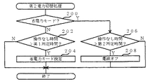
次に、図5を参照して、デジタルカメラ10において実行される第2電力切替処理について説明する。なお、図5は、前述の電力切替処理プログラム(図4も参照)の実行途中でデジタルカメラ10のCPU32により所定時間毎に割り込み処理として実行される第2電力切替処理プログラムの処理の流れを示すフローチャートである。
【0082】
同図のステップ200では、省電力モードに移行されているか否かを判定し、否定判定の場合はステップ202に移行して、操作部52(レリーズボタン60、モード切替スイッチ62、十字カーソルボタン64、電源スイッチ66)に対する操作が行われていない時間が上記第1の時間より長い時間として予め定めた第1所定時間(本発明の「第2の時間」に相当し、本実施の形態では3分。)を越えたか否かを判定し、肯定判定の場合はステップ204に移行して前述の電力切替処理(図4も参照)のステップ120の処理と同様にして省電力モードに移行させた後に本第2電力切替処理プログラムを終了し、否定判定の場合には上記ステップ204の処理を実行することなく本第2電力切替処理プログラムを終了する。
【0083】
一方、上記ステップ200において肯定判定された場合、すなわち、省電力モードに移行されている場合にはステップ206に移行し、操作部52に対する操作が行われていない時間が予め定めた第2所定時間(本実施の形態では5分。)を越えたか否かを判定し、肯定判定の場合はステップ208に移行して前述の電力切替処理のステップ134の処理と同様にして電源オフの状態とした後に本第2電力切替処理プログラムを終了し、否定判定の場合には上記ステップ208の処理を実行することなく本第2電力切替処理プログラムを終了する。
【0084】
本第2電力切替処理により、前述の電力切替処理によって省電力モードに移行されない場合であっても、操作部52に対する操作が第1所定時間を越えて行われない場合には自動的に省電力モードに移行させることができる。また、本第2電力切替処理により、前述の電力切替処理又は本第2電力切替処理により省電力モードに移行された後において、前述の電力切替処理によって通常のモードに復帰されない場合であっても、操作部52に対する操作が第2所定時間を越えて行われない場合には自動的に通常のモードに復帰させることができる。
【0085】
なお、本実施の形態では、被写体像に動きがあったか否かの判定に用いる測光データとして、被写体像の中心部に位置する4つの分割領域と、被写体像の四隅に各々位置する4つの分割領域の合計20の分割領域(図3の破線で囲まれた分割領域)の測光データを適用した場合について説明したが、本発明はこれに限定されるものではなく、例えば、撮影対象とする被写体の動作状態や処理速度の制限等に応じて被写体像の中心部に位置する分割領域のみを適用する形態や、被写体像の周辺部に位置する分割領域のみを適用する形態等とすることもできる。この場合も、本実施の形態と同様の効果を奏することができる。
【0086】
〔第2実施形態〕
上記第1実施形態では、被写体像の動きを検出するためにAE・AWB検出回路36によって検出された測光データを用いた形態について説明したが、本第2実施形態では、被写体像の動きを検出するために撮像によって得られたデジタル画像データを直接用いる形態について説明する。なお、本第2実施形態に係るデジタルカメラ10の構成は、上記第1実施形態に係るデジタルカメラ10と同一であるので、ここでの説明は省略する。また、本第2実施形態に係るデジタルカメラ10の撮影時における作用も上記第1実施形態と同一であるので、ここでの説明は省略する。
【0087】
以下、図6を参照して、本第2実施形態に係るデジタルカメラ10において実行される電力切替処理について説明する。なお、図6は、電源スイッチ66がオン状態とされているときに本第2実施形態に係るデジタルカメラ10のCPU32で実行される電力切替処理プログラムの処理の流れを示すフローチャートであり、図4に示されるプログラムと同一の処理を行うステップについては図4と同一のステップ番号を付して、その説明を省略する。
【0088】
図6のステップ100Bでは、この時点で第2メモリ40に記憶されているデジタル画像データ(ここでは、YC信号)を読み出して第1メモリ38の所定領域に記憶する。また、ステップ106Bでは、この時点で第2メモリ40に記憶されているデジタル画像データ(ここでは、YC信号)を読み出して第1メモリ38の他の所定領域に記憶する。
【0089】
そして、ステップ108Bでは、上記ステップ100B及びステップ106Bにおいて第1メモリ38に記憶したデジタル画像データに基づいて被写体像に動きがあったか否かを判定し、肯定判定の場合はステップ102に戻り、否定判定の場合にはステップ110に移行する。なお、本実施の形態に係るデジタルカメラ10では、上記ステップ108Bにおける被写体像に動きがあったか否かの判定を、上記ステップ106Bにおいて記憶したデジタル画像データと、上記ステップ100Bにおいて記憶したデジタル画像データとを対応する画素データ(ここでは、クロマ信号Cr)毎に各々比較し、画素データが所定値(本実施の形態では、上記ステップ100Bにおいて記憶した画素データの10%に相当する値)以上変化した画素データ数が所定数(本実施の形態では、被写体像1枚における全画素数の2分の1に相当する数)以上存在するか否かを判定することによって行う。
【0090】
なお、ステップ102〜ステップ108Bの処理を繰り返して実行する場合に上記ステップ108Bでは、直前のステップ106Bの処理によって記憶したデジタル画像データと、その前回のステップ106Bの処理によって記憶したデジタル画像データと、に基づいて被写体像に動きがあったか否かを判定する。また、ステップ104〜ステップ118の処理を繰り返して実行する場合にも上記ステップ108Bでは、直前のステップ106Bの処理によって記憶したデジタル画像データと、その前回のステップ106Bの処理によって記憶したデジタル画像データと、に基づいて被写体像に動きがあったか否かを判定する。
【0091】
一方、ステップ124Bでは、この時点で第2メモリ40に記憶されているデジタル画像データを読み出して第1メモリ38の所定領域に記憶する。そして、ステップ126Bでは、上記ステップ106B及びステップ124Bにおいて第1メモリ38に記憶したデジタル画像データに基づいて被写体像に動きがあったか否かを上記ステップ108Bと同様の手順で判定し、肯定判定の場合はステップ128に移行し、否定判定の場合にはステップ130に移行する。
【0092】
なお、ステップ122〜ステップ132の処理を繰り返して実行する場合に上記ステップ126Bでは、直前のステップ124Bの処理によって記憶したデジタル画像データと、その前回のステップ124Bの処理によって記憶したデジタル画像データと、に基づいて被写体像に動きがあったか否かを判定する。
【0093】
なお、本第2実施形態では、被写体像に動きがあったか否かの判定に用いるデジタル画像データとして被写体像の全域の画素データを適用した場合について説明したが、本発明はこれに限定されるものではなく、例えば、撮影対象とする被写体の動作状態や処理速度の制限等に応じて図3の破線で囲まれた分割領域内の画素データのみを適用する形態、被写体像の中心部に位置する分割領域内の画素データのみを適用する形態、被写体像の周辺部に位置する分割領域内の画素データのみを適用する形態等や、一部画素データを間引いた画像データを適用する形態等とすることもできる。この場合は、本実施の形態に比較して、被写体像の動きの判定精度がやや低下するものの、処理速度を高速化することができる。
【0094】
以上詳細に説明したように、上記各実施の形態に係るデジタルカメラ10では、撮像によって得られたデジタル画像データにより示される被写体像に上記第1の時間以上動きがなかったと判断されたときに省電力モードに移行させているので、的確なタイミングで省電力モードに移行することができる。
【0095】
また、上記各実施の形態に係るデジタルカメラ10では、省電力モードへの移行が行われない状態で操作部52に対する操作が上記第1の時間より長い第2の時間以上行われなかったときに省電力モードに移行させているので、より的確なタイミングで省電力モードに移行することができる。
【0096】
また、上記各実施の形態に係るデジタルカメラ10では、省電力モードに移行された後、被写体像に予め定めた第3の時間以上動きがなかったと判断されたときに電源オフの状態としているので、省電力効果を大幅に向上させることができる。
【0097】
また、上記各実施の形態に係るデジタルカメラ10では、省電力モードに移行された後で、かつ電源オフの状態とされる前に、被写体像に動きがあったと判断されたときに上記省電力モードを解除しているので、省電力モードに移行した後の通常のモードへの復帰の手間を無くすることができ、ユーザにとっての利便性を向上させることができる。
【0098】
また、上記各実施の形態に係るデジタルカメラ10では、デジタル画像データにより示される被写体像の全体的な明るさが所定レベル以下である場合、他の場合より上記第1の時間を短いものとしているので、省電力効果をより向上させることができる。
【0099】
また、本第2実施形態に係るデジタルカメラ10では、デジタル画像データの変化量に基づいて被写体像に動きがあったか否かを判断しているので、被写体像に動きがあったか否かの判断にマージンを設けることができ、柔軟性の高い判断を行うことができる。
【0100】
更に、上記第1実施形態に係るデジタルカメラ10では、デジタル画像データに基づいて得られる被写体像の複数の分割領域における測光レベルの変化量に基づいて被写体像に動きがあったか否かを判断しているので、当該判断を短時間に行うことができる。
【0101】
なお、上記各実施の形態において説明した各種処理プログラム(図4〜図6参照)の処理の流れは一例であり、本発明の主旨を逸脱しない範囲内において適宜変更可能であることは言うまでもない。
【0102】
【発明の効果】
請求項1に記載のデジタルカメラによれば、撮像によって得られた画像情報により示される被写体像に所定時間以上動きがなかったと判断されたときに省電力モードに移行させているので、的確なタイミングで省電力モードに移行することができる、という効果が得られる。
【0103】
また、請求項1に記載のデジタルカメラによれば、省電力モードへの移行が行われない状態で操作手段に対する操作が本発明の所定時間より長い第2の時間以上行われなかったときに省電力モードに移行させているので、より的確なタイミングで省電力モードに移行することができる、という効果が得られる。
【0104】
更に、請求項2に記載のデジタルカメラによれば、省電力モードに移行された後、被写体像に予め定めた第3の時間以上動きがなかったと判断されたときに電源オフの状態としているので、省電力効果を大幅に向上させることができる、という効果が得られる。
【図面の簡単な説明】
【図1】実施の形態に係るデジタルカメラ10の外観を示す外観図である。
【図2】実施の形態に係るデジタルカメラ10の電気系の構成を示すブロック図である。
【図3】実施の形態に係る測光データ及び分割領域の説明に供する概略図である。
【図4】第1実施形態に係る電力切替処理プログラムの処理の流れを示すフローチャートである。
【図5】電力切替処理プログラムの実行途中で割り込み処理として実行される第2電力切替処理プログラムの処理の流れを示すフローチャートである。
【図6】第2実施形態に係る電力切替処理プログラムの処理の流れを示すフローチャートである。
【符号の説明】
10 デジタルカメラ
14 CCD(撮像手段)
32 CPU(判断手段、移行手段、電源オフ手段、解除手段)
52 操作部(操作手段)
54 電源回路[0001]
BACKGROUND OF THE INVENTION
The present invention relates to a digital camera, and more particularly to power saving of a digital camera.
[0002]
[Prior art]
In recent years, the demand for digital cameras has increased rapidly with the increase in resolution of imaging devices such as CCD (Charge Coupled Device) and CMOS (Complementary Metal Oxide Semiconductor) image sensors.
[0003]
By the way, the electrical components used in this type of digital camera are the power consumption such as the imaging device, the high-speed CPU (Central Processing Unit), the liquid crystal display (hereinafter referred to as “LCD”), the backlight of the LCD, and the like. There are many big ones. On the other hand, this type of digital camera is presumed to be used in a mobile environment that is carried around, and due to the size and weight of the housing, a large battery or a large number of batteries cannot be used. For this reason, since power consumption is large compared with the capacity | capacitance of a battery, there are many models with short use time.
[0004]
In view of this point, in the technique described in Japanese Patent Laid-Open No. 2000-59675, the operation state of the apparatus is determined from the operation status of the switch for selecting an operation mode such as a recording mode and a playback mode, a power switch, and a release switch, and the apparatus When it is determined that the continuation time of the operation state exceeds a predetermined time corresponding to each operation state, the mode is shifted to the power saving mode.
[0005]
[Problems to be solved by the invention]
However, in the technique described in Japanese Patent Laid-Open No. 2000-59675, when a state in which various switches are not operated continues for a predetermined time, the mode is unconditionally shifted to the power saving mode. There is a problem in that even when the operation of the switches is not performed, such as when the direction of the camera is changed, the mode is shifted to the power saving mode. In this case, it is necessary to cancel the power saving mode for shooting, and the convenience for the user is significantly impaired.
[0006]
Further, when the digital camera is stored in a pocket, bag, storage case or the like without turning off the power switch, it is desired to shift to the power saving mode as soon as possible. However, in the technique described in the above Japanese Patent Laid-Open No. 2000-59675, Even in such a case, there is a problem that the mode does not shift to the power saving mode until a predetermined time elapses. In order to solve this problem, the predetermined time may be set short. In this case, the digital camera shifts to a power saving mode when the direction of the digital camera is changed to determine the shooting scene. There is a new problem that it is easy to shift to the power saving mode even when it is not desired.
[0007]
The present invention has been made to solve the above-described problems, and an object of the present invention is to provide a digital camera that can shift to a power saving mode at an accurate timing.
[0008]
[Means for Solving the Problems]
In order to achieve the above object, the digital camera according to
[0009]
According to the digital camera of the first aspect, the subject is imaged by the imaging unit to obtain image information indicating the subject image, and the determination unit determines whether or not the subject image has moved based on the image information. The Note that the imaging means includes a solid-state imaging device such as a CCD or a CMOS image sensor.
[0010]
According to the first aspect of the present invention, when the determination unit determines that the subject image has not moved for a predetermined time or more, the shift unit shifts to the power saving mode for reducing power consumption.
[0011]
In other words, even if the switches on the digital camera are not operated, the subject to be photographed can be placed in the viewfinder or the viewfinder can be set as a state where it is not desired to shift to the power saving mode. In most cases, the shooting direction of the digital camera is changed in order to determine the composition of the subject within the image. In this state, since the shooting direction of the digital camera is changed, in most cases, the subject image indicated by the image information obtained by the imaging is in a state of movement.
[0012]
In the present invention, focusing on this point, when it is determined that the subject image has not moved for a predetermined time or more, the mode is shifted to the power saving mode. When the state that is not performed continues, it is possible to shift to the power saving mode at a more accurate timing than the prior art that shifts to the power saving mode.
[0013]
In addition, since the present invention shifts to the power saving mode when the subject image does not move, even when the digital camera is stored in a pocket, bag, storage case, etc. without turning off the power switch. In this case, the subject image does not move, so that it is possible to quickly shift to the power saving mode.
[0014]
As described above, according to the digital camera of the first aspect, when it is determined that the subject image indicated by the image information obtained by imaging has not moved for a predetermined time or more, the mode is shifted to the power saving mode. It is possible to shift to the power saving mode at an appropriate timing.
[0016]
Also,Claim1According to the digital camera described in the above, the operation means is operated to perform various operations. The operation means includes a release switch that is operated when shooting, a mode switch that is operated when setting an operation mode, a zoom button that is operated when enlarging or reducing the subject image, and the like. All switches and buttons provided in the digital camera are included.
[0017]
Where the claim1In the invention described in the above, when the operation of the operation unit is not performed for a second time longer than the predetermined time without the shift unit performing the shift to the power saving mode by the shift unit, the power save mode is set. To be migrated.
[0018]
That is, in the present invention, even when the subject image indicated by the image information continuously moves, if the operation with respect to the operation means is not continuously performed, it is considered that there is no intention to perform shooting. Thus, the mode is shifted to the power saving mode, whereby the mode can be shifted to the power saving mode at a more appropriate timing.
[0019]
Thus, the claim1According to the digital camera described in the above, when the operation on the operation unit is not performed for the second time longer than the predetermined time of the present invention without the transition to the power saving mode, the operation mode is shifted to the power saving mode. Therefore, it is possible to shift to the power saving mode at a more accurate timing.
[0020]
Further claims2The described digital camera is claimed1In the described invention, after the transition unit shifts to the power saving mode, the determination unit determines that the subject image has not moved for a predetermined third time or more, and the power is turned off. A power-off means is further provided.
[0021]
Claim2According to the digital camera described in the above, when the transition unit of the present invention shifts to the power saving mode and then the determination unit of the present invention determines that the subject image has not moved for a predetermined third time or more. The power is turned off by the power off means.
[0022]
In other words, in the present invention, even if the subject image indicated by the image information obtained by imaging does not move continuously even after shifting to the power saving mode, imaging is not performed for a while. In view of this, the power is turned off, and this can greatly improve the power saving effect.
[0023]
Thus, the claim2According to the digital camera described in claim1The effect similar to that of the described invention can be obtained, and the power-off state is set when it is determined that the subject image has not moved for a predetermined third time or more after the shift to the power saving mode. The power saving effect can be greatly improved.
[0024]
The above claims2As a preferred aspect of the described invention (hereinafter referred to as “first aspect”), after the transition unit shifts to the power saving mode and before the power off unit sets the power off state. An aspect may further include a cancellation unit that cancels the power saving mode when the determination unit determines that the subject image has moved.
[0025]
According to the digital camera of the first aspect, it is assumed that the subject image has moved by the determining unit after the shift unit has shifted to the power saving mode and before the power-off unit has been turned off. When judged, the power saving mode is canceled by the canceling means.
[0026]
Thus, according to the digital camera of the first aspect, the claims2The above-described power saving can be achieved when it is determined that the subject image has moved after the transition to the power saving mode and before the power is turned off. Since the mode is released, the trouble of returning to the normal mode after shifting to the power saving mode can be eliminated, and convenience for the user can be improved.
[0027]
Further, as a preferred aspect of the present invention (hereinafter referred to as “second aspect”), when the overall brightness of the subject image indicated by the image information is equal to or lower than a predetermined level, the predetermined brightness is higher than in other cases. An embodiment in which the time is short can be mentioned.
[0028]
That is, when the digital camera is stored in a pocket, bag, storage case or the like without turning off the power switch, the subject image indicated by the image information obtained by the imaging is uniformly dark.
[0029]
Focusing on this point, in the digital camera according to the second aspect, if the overall brightness of the subject image indicated by the image information is not more than a predetermined level, it is considered that the digital camera is housed. The predetermined time is shorter than in other cases, so that the timing of shifting to the power saving mode when the digital camera is housed is earlier than in other cases, so that the power saving effect can be improved. Yes.
[0030]
Thus, according to the digital camera of the second aspect,OrClaim2The same effect as that of the described invention can be obtained, and when the overall brightness of the subject image indicated by the image information is below a predetermined level, the predetermined time of the present invention is shorter than the other cases. The power saving effect can be further improved.
[0031]
As a preferred aspect of the present invention (hereinafter referred to as “third aspect”), the determination unit may determine whether or not the subject image has moved based on the amount of change in the image information. be able to.
[0032]
According to the digital camera of the third aspect, the determination unit determines whether or not the subject image has moved based on the change amount of the image information. More specifically, it is assumed that the subject image has moved when the change amount of the image information is a predetermined amount or more, and the subject image has not moved in other cases.
[0033]
Thus, according to the digital camera of the third aspect,OrClaim2The effect similar to that of the described invention can be obtained, and since it is determined whether or not the subject image has moved based on the amount of change in the image information, there is a margin in determining whether or not the subject image has moved. It can be provided and a highly flexible judgment can be made.
[0034]
Furthermore, as a preferred aspect of the invention according to the third aspect (hereinafter, referred to as “fourth aspect”), the determination means includes a photometric level in a plurality of divided regions of the subject image obtained based on the image information. An example of determining whether or not the subject image has moved based on the amount of change of the subject can be given.
[0035]
According to the digital camera of the fourth aspect, the determination unit determines whether or not the subject image has moved based on the amount of change in the photometric level in the plurality of divided regions of the subject image obtained based on the image information. The
[0036]
That is, many current digital cameras detect photometric levels in a plurality of divided regions of a subject image based on image information in order to realize an automatic exposure function. Focusing on this point, in the digital camera according to the fourth aspect, the photometry level is used as information based on the image information, and the presence or absence of movement of the subject image is determined based on the amount of change in the photometry level. This makes it possible to make a determination in a shorter time than in the case where the determination is made using the image information itself.
[0037]
As described above, according to the digital camera of the fourth aspect, the same effects as those of the invention of the third aspect can be obtained, and photometry in a plurality of divided regions of the subject image obtained based on the image information can be obtained. Since it is determined whether or not the subject image has moved based on the level change amount, the determination can be made in a short time.
[0038]
DETAILED DESCRIPTION OF THE INVENTION
Hereinafter, embodiments of the present invention will be described in detail with reference to the drawings.
[0039]
[First Embodiment]
First, an external configuration of the
[0040]
Note that the release button 60 according to the present embodiment is in a state where the release button 60 is pressed down to an intermediate position (hereinafter referred to as “half-pressed state”) and a state where the release button 60 is pressed down to a final pressed position beyond the intermediate position (hereinafter, referred to as “lower pressed state”). It is configured to be able to detect a two-stage pressing operation of “fully pressed state”. In the
[0041]
On the other hand, on the back of the
[0042]
On the other hand, on the side of the
[0043]
Next, the configuration of the electrical system of the
[0044]
As shown in the figure, the
[0045]
Here, the correlated double sampling processing by the
[0046]
On the other hand, the
[0047]
Further, the
[0048]
Further, the
[0049]
[0050]
Therefore, the
[0051]
On the other hand, the
[0052]
Further, the
[0053]
The lens 12 included in the optical unit 13 according to the present embodiment has a plurality of lenses, and is configured as a zoom lens that can change (magnify) the focal length, and includes a lens driving mechanism (not shown). Yes. The lens drive mechanism includes the focus adjustment motor, the zoom motor, and the aperture drive motor. The focus adjustment motor, the zoom motor, and the aperture drive motor are each supplied with a drive signal supplied from the
[0054]
When changing the optical zoom magnification, the
[0055]
Further, the
[0056]
Further, the various buttons and switches (generally referred to as “
[0057]
The
[0058]
By the way, in the AE / AWB detection circuit 36 according to the present embodiment, as shown in FIG. 3, a predetermined number × predetermined number of subject images indicated by digital image data obtained by imaging by the CCD 14 (in this embodiment) , 8 × 8) divided areas, and photometric data indicating the average brightness of the divided areas is sequentially derived for each divided area. Therefore, the
[0059]
The CCD 14 corresponds to the image pickup means of the present invention, the
[0060]
Next, the operation of the
[0061]
A signal indicating the subject image output from the CCD 14 by imaging through the optical unit 13 is sequentially input to the
[0062]
The
[0063]
The digital image data stored in the predetermined area of the
[0064]
The
[0065]
Here, when the release button 60 is fully pressed by the user, the YC signal stored in the
[0066]
Next, with reference to FIG. 4, the power switching process executed in the
[0067]
In
[0068]
In the
[0069]
In the
[0070]
In the
[0071]
In
[0072]
In
[0073]
In
[0074]
As a result of the above processing, while it is recognized that the subject image is moving, the processing of
[0075]
In the
[0076]
In the next step 126, it is determined whether or not the subject image has moved based on the photometric data stored in the
[0077]
In
[0078]
In step 134, the same process as when the power switch 66 is turned off is performed to turn the power off, and then the power switching process program is terminated.
[0079]
A predetermined time (determined in accordance with the predetermined time during which the process waits in
[0080]
On the other hand, if it is not recognized that the subject image has moved during the period from the transition to the power saving mode until the third time elapses, it is assumed that it is the timing to turn off the power. In step 134, the power is off.
[0081]
Next, the second power switching process executed in the
[0082]
In
[0083]
On the other hand, if an affirmative determination is made in
[0084]
Even if the second power switching process does not shift to the power saving mode by the power switching process, the power saving is automatically performed when the operation on the
[0085]
In the present embodiment, as the photometric data used for determining whether or not the subject image has moved, four divided regions located at the center of the subject image and four divided regions located at the four corners of the subject image, respectively. However, the present invention is not limited to this, and the present invention is not limited to this. For example, the subject to be photographed It is also possible to adopt a form in which only a divided area located at the center of the subject image is applied or a form in which only a divided area located at the periphery of the subject image is applied according to the operating state, processing speed limitation, or the like. Also in this case, the same effects as in the present embodiment can be obtained.
[0086]
[Second Embodiment]
In the first embodiment, the mode using the photometric data detected by the AE / AWB detection circuit 36 to detect the motion of the subject image has been described. However, in the second embodiment, the motion of the subject image is detected. In order to achieve this, a mode in which digital image data obtained by imaging is directly used will be described. The configuration of the
[0087]
Hereinafter, with reference to FIG. 6, the power switching process executed in the
[0088]
In step 100B of FIG. 6, the digital image data (here, YC signal) stored in the
[0089]
In step 108B, it is determined whether or not the subject image has moved based on the digital image data stored in the
[0090]
In the case where the processing of
[0091]
On the other hand, in step 124B, the digital image data stored in the
[0092]
In the case where the processing of
[0093]
In the second embodiment, the case where the pixel data of the entire area of the subject image is applied as the digital image data used to determine whether or not the subject image has moved has been described. However, the present invention is not limited to this. Instead, for example, a mode in which only pixel data in the divided area surrounded by a broken line in FIG. 3 is applied according to the operation state of the subject to be photographed, processing speed limitation, and the like, located in the center of the subject image A mode in which only pixel data in the divided area is applied, a mode in which only pixel data in the divided area located in the periphery of the subject image is applied, a mode in which image data obtained by thinning out part of the pixel data is applied, etc. You can also. In this case, the processing speed can be increased although the determination accuracy of the movement of the subject image is slightly lowered as compared with the present embodiment.
[0094]
As described above in detail, in the
[0095]
Further, in the
[0096]
Further, in the
[0097]
Further, in the
[0098]
In the
[0099]
Further, in the
[0100]
Further, in the
[0101]
It should be noted that the processing flow of the various processing programs (see FIGS. 4 to 6) described in the above embodiments is merely an example, and it is needless to say that the flow can be appropriately changed without departing from the gist of the present invention.
[0102]
【The invention's effect】
According to the digital camera of the first aspect, since it is shifted to the power saving mode when it is determined that the subject image indicated by the image information obtained by imaging has not moved for a predetermined time or more, the accurate timing is obtained. Thus, the effect of being able to shift to the power saving mode can be obtained.
[0103]
Claims1According to the digital camera described in (1), when the operation on the operation means is not performed for a second time longer than the predetermined time of the present invention without being shifted to the power saving mode, the operation mode is shifted to the power saving mode. Therefore, it is possible to obtain an effect that the mode can be shifted to the power saving mode at a more accurate timing.
[0104]
Further claims2According to the digital camera described above, since the power-off state is determined when it is determined that the subject image has not moved for a predetermined third time or more after the transition to the power saving mode, the power saving effect is achieved. The effect that it can improve significantly is acquired.
[Brief description of the drawings]
FIG. 1 is an external view showing an external appearance of a
FIG. 2 is a block diagram showing a configuration of an electric system of the
FIG. 3 is a schematic diagram for explaining photometric data and divided areas according to the embodiment.
FIG. 4 is a flowchart showing a process flow of a power switching process program according to the first embodiment.
FIG. 5 is a flowchart showing a process flow of a second power switching process program executed as an interrupt process in the middle of execution of the power switching process program.
FIG. 6 is a flowchart showing a process flow of a power switching process program according to the second embodiment.
[Explanation of symbols]
10 Digital camera
14 CCD (imaging means)
32 CPU (determination means, transition means, power-off means, release means)
52 Operation part (operation means)
54 Power supply circuit
Claims (2)
前記撮像手段により得られた前記画像情報に基づいて前記被写体像に動きがあったか否かを判断する判断手段と、
前記判断手段により前記被写体像に所定時間以上動きがなかったと判断されたときに消費電力を低減させる省電力モードに移行させる移行手段と、
各種操作を行うために操作される操作手段と、を備え、
前記移行手段は、当該移行手段による前記省電力モードへの移行を行わない状態で前記操作手段に対する操作が前記所定時間より長い第2の時間以上行われなかったときに前記省電力モードに移行させるデジタルカメラ。 Imaging means for imaging a subject to obtain image information indicating a subject image;
Determining means for determining whether or not the subject image has moved based on the image information obtained by the imaging means;
Transition means for shifting to a power saving mode for reducing power consumption when it is determined by the determination means that the subject image has not moved for a predetermined time or more;
Operating means operated to perform various operations,
The transition means shifts to the power saving mode when an operation on the operation means is not performed for a second time longer than the predetermined time in a state where the transition means does not shift to the power saving mode. Digital camera.
を更に備えた請求項1記載のデジタルカメラ。And a power-off means for turning off the power when the judgment means judges that the subject image has not moved for a predetermined third time or more after the transition means has shifted to the power saving mode. The digital camera according to claim 1, further comprising:
Priority Applications (1)
| Application Number | Priority Date | Filing Date | Title |
|---|---|---|---|
| JP2002176222A JP4034603B2 (en) | 2002-06-17 | 2002-06-17 | Digital camera |
Applications Claiming Priority (1)
| Application Number | Priority Date | Filing Date | Title |
|---|---|---|---|
| JP2002176222A JP4034603B2 (en) | 2002-06-17 | 2002-06-17 | Digital camera |
Related Child Applications (1)
| Application Number | Title | Priority Date | Filing Date |
|---|---|---|---|
| JP2007247879A Division JP4227181B2 (en) | 2007-09-25 | 2007-09-25 | Digital camera |
Publications (2)
| Publication Number | Publication Date |
|---|---|
| JP2004023476A JP2004023476A (en) | 2004-01-22 |
| JP4034603B2 true JP4034603B2 (en) | 2008-01-16 |
Family
ID=31174642
Family Applications (1)
| Application Number | Title | Priority Date | Filing Date |
|---|---|---|---|
| JP2002176222A Expired - Fee Related JP4034603B2 (en) | 2002-06-17 | 2002-06-17 | Digital camera |
Country Status (1)
| Country | Link |
|---|---|
| JP (1) | JP4034603B2 (en) |
Families Citing this family (4)
| Publication number | Priority date | Publication date | Assignee | Title |
|---|---|---|---|---|
| JP4648173B2 (en) * | 2005-12-01 | 2011-03-09 | オリンパス株式会社 | Microscope digital camera, control method and program for microscope digital camera |
| JP2008227672A (en) * | 2007-03-09 | 2008-09-25 | Fujitsu Ltd | Portable terminal, power saving control method, and power saving control program |
| US8085338B2 (en) | 2008-05-16 | 2011-12-27 | Panasonic Corporation | Imaging apparatus and camera system |
| JP5832373B2 (en) * | 2012-05-16 | 2015-12-16 | キヤノン株式会社 | Interchangeable lens device and camera device |
-
2002
- 2002-06-17 JP JP2002176222A patent/JP4034603B2/en not_active Expired - Fee Related
Also Published As
| Publication number | Publication date |
|---|---|
| JP2004023476A (en) | 2004-01-22 |
Similar Documents
| Publication | Publication Date | Title |
|---|---|---|
| JP4497912B2 (en) | Camera and zoom control method of camera | |
| JP4446787B2 (en) | Imaging apparatus and display control method | |
| JP2012165090A (en) | Imaging apparatus and control method of the same | |
| JP4000293B2 (en) | Digital camera | |
| JP5339802B2 (en) | Imaging apparatus and control method thereof | |
| CN101277392B (en) | Electronic device, image display method | |
| JP2004157353A (en) | Camera having operation member with pressure sensor | |
| JP4136958B2 (en) | Digital camera and digital camera control method | |
| JP4034603B2 (en) | Digital camera | |
| JP2004080285A (en) | Digital camera | |
| JP2009223056A (en) | Photographic apparatus and method | |
| JP3750500B2 (en) | Electronic camera and photographing method | |
| JP4227181B2 (en) | Digital camera | |
| JP2003255428A (en) | camera | |
| JP2009049639A (en) | Imaging device | |
| JP4355855B2 (en) | Imaging apparatus, shooting switching method, and program | |
| JP2003319213A (en) | Imaging device | |
| JP2006221103A (en) | IMAGING DEVICE AND IMAGING DEVICE CONTROL PROGRAM | |
| JP4558108B2 (en) | Information processing apparatus, information processing method, and recording medium | |
| JP7558280B2 (en) | Imaging device, imaging method, and imaging program | |
| JP4369350B2 (en) | Imaging device | |
| JP4335750B2 (en) | Imaging apparatus and photographing aspect ratio confirmation method | |
| JPH10294919A (en) | Information processing device and recording medium | |
| JP5686869B2 (en) | Imaging device | |
| JP4181352B2 (en) | Digital camera |
Legal Events
| Date | Code | Title | Description |
|---|---|---|---|
| A621 | Written request for application examination |
Free format text: JAPANESE INTERMEDIATE CODE: A621 Effective date: 20050210 |
|
| A711 | Notification of change in applicant |
Free format text: JAPANESE INTERMEDIATE CODE: A712 Effective date: 20061212 |
|
| A977 | Report on retrieval |
Free format text: JAPANESE INTERMEDIATE CODE: A971007 Effective date: 20070709 |
|
| A131 | Notification of reasons for refusal |
Free format text: JAPANESE INTERMEDIATE CODE: A131 Effective date: 20070724 |
|
| A521 | Request for written amendment filed |
Free format text: JAPANESE INTERMEDIATE CODE: A523 Effective date: 20070925 |
|
| TRDD | Decision of grant or rejection written | ||
| A01 | Written decision to grant a patent or to grant a registration (utility model) |
Free format text: JAPANESE INTERMEDIATE CODE: A01 Effective date: 20071023 |
|
| A61 | First payment of annual fees (during grant procedure) |
Free format text: JAPANESE INTERMEDIATE CODE: A61 Effective date: 20071025 |
|
| FPAY | Renewal fee payment (event date is renewal date of database) |
Free format text: PAYMENT UNTIL: 20101102 Year of fee payment: 3 |
|
| R150 | Certificate of patent or registration of utility model |
Ref document number: 4034603 Country of ref document: JP Free format text: JAPANESE INTERMEDIATE CODE: R150 Free format text: JAPANESE INTERMEDIATE CODE: R150 |
|
| FPAY | Renewal fee payment (event date is renewal date of database) |
Free format text: PAYMENT UNTIL: 20111102 Year of fee payment: 4 |
|
| R250 | Receipt of annual fees |
Free format text: JAPANESE INTERMEDIATE CODE: R250 |
|
| FPAY | Renewal fee payment (event date is renewal date of database) |
Free format text: PAYMENT UNTIL: 20121102 Year of fee payment: 5 |
|
| R250 | Receipt of annual fees |
Free format text: JAPANESE INTERMEDIATE CODE: R250 |
|
| FPAY | Renewal fee payment (event date is renewal date of database) |
Free format text: PAYMENT UNTIL: 20121102 Year of fee payment: 5 |
|
| FPAY | Renewal fee payment (event date is renewal date of database) |
Free format text: PAYMENT UNTIL: 20131102 Year of fee payment: 6 |
|
| R250 | Receipt of annual fees |
Free format text: JAPANESE INTERMEDIATE CODE: R250 |
|
| R250 | Receipt of annual fees |
Free format text: JAPANESE INTERMEDIATE CODE: R250 |
|
| R250 | Receipt of annual fees |
Free format text: JAPANESE INTERMEDIATE CODE: R250 |
|
| R250 | Receipt of annual fees |
Free format text: JAPANESE INTERMEDIATE CODE: R250 |
|
| R250 | Receipt of annual fees |
Free format text: JAPANESE INTERMEDIATE CODE: R250 |
|
| R250 | Receipt of annual fees |
Free format text: JAPANESE INTERMEDIATE CODE: R250 |
|
| R250 | Receipt of annual fees |
Free format text: JAPANESE INTERMEDIATE CODE: R250 |
|
| R250 | Receipt of annual fees |
Free format text: JAPANESE INTERMEDIATE CODE: R250 |
|
| R250 | Receipt of annual fees |
Free format text: JAPANESE INTERMEDIATE CODE: R250 |
|
| LAPS | Cancellation because of no payment of annual fees |