JP4034026B2 - Construction equipment working equipment - Google Patents
Construction equipment working equipment Download PDFInfo
- Publication number
- JP4034026B2 JP4034026B2 JP2000117029A JP2000117029A JP4034026B2 JP 4034026 B2 JP4034026 B2 JP 4034026B2 JP 2000117029 A JP2000117029 A JP 2000117029A JP 2000117029 A JP2000117029 A JP 2000117029A JP 4034026 B2 JP4034026 B2 JP 4034026B2
- Authority
- JP
- Japan
- Prior art keywords
- hook
- work tool
- pin
- mounting pin
- arm
- Prior art date
- Legal status (The legal status is an assumption and is not a legal conclusion. Google has not performed a legal analysis and makes no representation as to the accuracy of the status listed.)
- Expired - Fee Related
Links
- 238000010276 construction Methods 0.000 title claims description 20
- 230000008878 coupling Effects 0.000 claims description 21
- 238000010168 coupling process Methods 0.000 claims description 21
- 238000005859 coupling reaction Methods 0.000 claims description 21
- 230000002093 peripheral effect Effects 0.000 description 15
- 238000005452 bending Methods 0.000 description 3
- 238000013459 approach Methods 0.000 description 2
- 230000004048 modification Effects 0.000 description 2
- 238000012986 modification Methods 0.000 description 2
- 238000009412 basement excavation Methods 0.000 description 1
- 210000000078 claw Anatomy 0.000 description 1
- 238000007596 consolidation process Methods 0.000 description 1
- 230000000694 effects Effects 0.000 description 1
- 230000002265 prevention Effects 0.000 description 1
Images


Landscapes
- Shovels (AREA)
Description
【0001】
【発明の属する技術分野】
本発明は、例えば土木作業、建設作業を行うのに好適に用いられる油圧ショベル等の建設機械の作業装置に関し、特に、複数種類の作業具を交換して取付ける構成とした建設機械の作業装置に関する。
【0002】
【従来の技術】
一般に、油圧ショベル等の建設機械に用いる作業装置は、上部旋回体の前側に俯仰動可能に設けられたブームと、該ブームの先端側に俯仰動可能に設けられたアームと、該アームの先端側に回動可能に設けられたバケット等の作業具と、前記ブーム、アームおよび作業具をそれぞれ駆動する油圧シリンダとによって大略構成されている。
【0003】
また、油圧ショベルの作業装置には、形状や大きさの異なる複数種類のバケットを交換して取付けたり、例えば掘削作業、突き崩し作業、地固め作業等の作業内容に応じてバケット、ブレーカ、タンパ等の作業具を交換して取付ける構造を備えたものがあり、このような作業装置を有する油圧ショベルは、1台の車両で複数種類の作業を行なうことができる。
【0004】
この種の従来技術による作業装置は、例えば特開平9−209391号公報(以下、第1の従来技術という)、特開平11−117345号公報(以下、第2の従来技術という)等によって知られている。この作業装置は、アームの先端側に作業具連結手段を備え、作業具には該作業具連結手段に係合する第1,第2の取付ピンを有し、該作業具は作業具連結手段に各取付ピンを介して着脱可能(交換可能)に取付ける構成としている。
【0005】
ここで、第1の従来技術による作業具連結手段は、作業具に設けられた第1,第2の取付ピンのうち、一方の取付ピンに係合する切欠きを有するブラケットと、該ブラケットに揺動可能に設けられ、他方のピンに係合する切欠きを有するアームと、前記ブラケットとアームとの間に設けられ、ブラケットに対してアームを揺動し、ブラケットの切欠きとアームの切欠きとの間隔を接近、離間する油圧シリンダ等の開閉装置とによって大略構成している。
【0006】
そして、第1の従来技術による作業具連結手段は、油圧シリンダによってブラケットの切欠きとアームの切欠きとを接近させ、この状態でブラケットとアームを作業具の第1,第2の取付ピン間に配置する。次に、油圧シリンダによりブラケットの切欠きとアームの切欠きとを離間させ、該各切欠きを取付ピンに係合する。これにより、作業具連結手段は、作業具の各取付ピンに内側から係合するから、作業具を着脱可能に保持することができる。
【0007】
また、第2の従来技術による作業具連結手段は、アームの先端にカプラを設け、該カプラには、作業具に設けられた第1,第2の取付ピンのうち、一方の取付ピンに係合するフック部を一体に設け、また、作業具の他方の取付ピンが挿通するピン穴を有するカプラリンクを回動可能に設ける構成としている。
【0008】
そして、第2の従来技術による作業具連結手段は、カプラに一体に設けられたフック部を作業具の一方の取付ピンに係合させ、また、他方の取付ピンを作業具のブラケットとカプラリンクのピン穴とに挿通する。これにより、作業具連結手段は、作業具の各取付ピンに係合し、該作業具を着脱可能に保持することができる。
【0009】
【発明が解決しようとする課題】
ところで、特開平9−209391号公報に記載された第1の従来技術による油圧ショベルの作業装置では、ブラケットとアームとの間に油圧シリンダを設けているから、作業具連結手段の構造が複雑になる上に、油圧シリンダを駆動するためのホース等が必要になり、作業装置全体としてコストの上昇、組立作業性の低下等を招くという問題がある。
【0010】
また、特開平11−117345号公報に記載された第2の従来技術による油圧ショベルの作業装置では、カプラリンクをバケットのブラケットに取付けるときに、作業具のブラケットに形成されたピン穴とカプラリンクのピン穴とを位置合わせし、これらのピン穴に亘って取付ピンを挿入しなくてはならず、位置合わせ作業に時間を要するから、組立作業性が低下するという問題がある。
【0011】
一方、第1、第2の従来技術による作業具連結手段は、作業具を交換するときに、他の作業具に設けられた第1の取付ピンと第2の取付ピンとの間隔が異なる場合には、油圧シリンダによるブラケットとアームの開き寸法を調整したり、フック部とカプラリンクとの回動角度を調整したりすることにより対応することができる。
【0012】
しかし、作業具に設けられた取付ピンの長さ寸法、即ち取付ピンの両端側を支持しているブラケット間の寸法が異なる場合には、これに対応することができない。このため、作業具連結手段に作業具を取付けることができたとしても、作業具によってはブラケットと作業具連結手段との間に隙間が形成されてしまい、この隙間により取付ピンの軸方向にがたつきを生じてしまうという問題がある。
【0013】
本発明は上述した従来技術の問題に鑑みなされたもので、本発明の目的は、油圧シリンダ等のアクチュエータを用いることなく作業具を着脱することができ、作業具連結手段の構成を簡略化することができるようにした建設機械の作業装置を提供することにある。
【0014】
また、本発明の他の目的は、作業具に設けられた取付ピンを抜き差しすることなく、簡単な作業で作業具を交換することができるようにした建設機械の作業装置を提供することにある。
【0015】
また、本発明の他の目的は、作業具連結手段に対して作業具ががたつくのを防止して、作業性、信頼性を向上することができるようにした建設機械の作業装置を提供することにある。
【0016】
さらに、本発明の他の目的は、作業具連結手段にブラケットの間隔が異なる他の作業具を連結したときに、作業具が作業具連結手段に対してがたつくのを防止し、種々の作業具を利用することができるようにした建設機械の作業装置を提供することにある。
【0017】
【課題を解決するための手段】
請求項1の発明による油圧ショベルの作業装置は、車体のフレームに俯仰動可能に取付けられたブームと、該ブームの先端側に俯仰動可能に設けられたアームと、該アームの先端側に設けられた作業具連結手段と、ブラケットに設けられた第1,第2の取付ピンにより該作業具連結手段を用いて前記アームの先端側に着脱可能に取付けられる作業具とによって構成している。
【0018】
そして、上述した課題を解決するために、請求項1の発明が採用する構成の特徴は、作業具連結手段は、アームの先端側に取付けられるフック支持体と、該フック支持体に固定して設けられ作業具の第1,第2の取付ピンのうち一方の取付ピンに係合する固定フックと、前記フック支持体に回動可能に設けられ他方の取付ピンに係合する回動フックと、該回動フックに対して相対移動可能に設けられ該回動フックと一緒に他方の取付ピンに係合することにより回動フックの抜止めを行なう抜止め部材とにより構成し、前記回動フックは、基端側を前記フック支持体に設けられた連結ピンに回動可能に取付けると共に先端側に他方の取付ピンに係合する切欠開口を設ける構成とし、前記抜止め部材は、基端側を前記連結ピンの径方向にスライド可能に取付けると共に先端側に他方の取付ピンに係合する切欠開口を設ける構成としたことにある。
【0019】
このように構成したことにより、第1,第2の取付ピンのうち、一方の取付ピンに外周側から固定フックを係合し、この状態で回動フックを揺動しつつ外周側から他方の取付ピンに係合し、続いて抜止め部材を他の取付ピンに外周側から係合することによって、作業具連結手段と作業具との間には、固定フック、回動フック、作業具等によって三角形を形成することができるから、作業具連結手段に対して作業具を強固に支持することができる。しかも、固定フック、回動フックおよび抜止め部材は、いずれも取付ピンに外周側から係合する構成としているから、これらを取付ピンに対して容易に係合、離脱することができる。
また、回動フックは、基端側をフック支持体に設けられた連結ピンに回動可能に取付けると共に先端側に他方の取付ピンに係合する切欠開口を設ける構成とし、抜止め部材は、基端側を前記連結ピンの径方向にスライド可能に取付けると共に先端側に他方の取付ピンに係合する切欠開口を設ける構成としているので、回動フックを作業具の他方の取付ピンに近付けた状態で、該回動フックが回動(揺動)することにより、その切欠開口は他方の取付ピンに外周側から容易に係合することができる。さらに、抜止め部材が前記連結ピンの径方向にスライドすることにより、その切欠開口は他方の取付ピンに容易に係合することができる。
【0020】
一方、請求項2の発明が採用する構成の特徴は、作業具連結手段は、アームの先端側に取付けられるフック支持体と、該フック支持体に固定して設けられ作業具の第1,第2の取付ピンのうち一方の取付ピンに係合する固定フックと、前記フック支持体に回動可能に設けられ他方の取付ピンに係合する回動フックと、該回動フックに対して相対移動可能に設けられ該回動フックと一緒に他方の取付ピンに係合することによって回動フックの抜止めを行なう抜止め部材とにより構成し、前記フック支持体には前記回動フックを回動可能に支持する連結ピンを設け、前記抜止め部材には該連結ピンが挿通される長穴状のガイド穴を設け、前記抜止め部材は、回動フックに対し該ガイド穴に沿って相対移動することにより前記他方の取付ピンに係合するラッチ板により構成したことにある。
【0021】
このように構成したことにより、請求項1の発明と同様に、作業具連結手段と作業具との間には、固定フック、回動フック、作業具等によって三角形を形成することができ、作業具連結手段に対して作業具を強固に支持することができる。しかも、固定フック、回動フックおよび抜止め部材 ( ラッチ板)は、いずれも取付ピンに外周側から係合する構成としているから、これらを取付ピンに対して容易に係合、離脱することができる。そして、ラッチ板はフック支持体の連結ピンに回動フックと一緒に取付けることができる。さらに、ラッチ板は、長穴状のガイド穴により回動フックに対して移動可能となっているから、該ガイド穴に沿って移動することができ、他方の取付ピンに係合、離脱することができる。
【0022】
請求項3の発明によると、回動フックと抜止め部材との間には、該回動フックと抜止め部材を他方の取付ピンに係合させた状態で両者を一体的に固定する固定部材を設けたことにある。
【0023】
このように構成したことにより、固定部材は、回動フックと抜止め部材を他方の取付ピンに係合させた状態で両者を一体的に固定することができるから、作業時等に抜止め部材が他方の取付ピンから離脱するのを防止することができる。
【0024】
請求項4の発明によると、固定フックには、該固定フックを作業具の一方の取付ピンに係合させたときに作業具のブラケットに対して弾性的に当接する弾性体を設けたことにある。
【0025】
このように構成したことにより、取付ピンを支持しているブラケットと固定フックとの間に隙間がある場合でも、弾性体は、固定フックを作業具の一方の取付ピンに取付けたときに作業具のブラケットに弾性的に当接し、該ブラケットと固定フックとの間の隙間を埋めてがたつきを抑えることができる。
【0026】
請求項5の発明によると、抜止め部材には、該抜止め部材を作業具の他方の取付ピンに係合させたときに作業具のブラケットに対して弾性的に当接する弾性体を設けたことにある。
【0027】
このように構成したことにより、取付ピンを支持しているブラケットと抜止め部材との間に隙間がある場合でも、弾性体は、抜止め部材を作業具の他方の取付ピンに取付けたときに作業具のブラケットに弾性的に当接するから、該ブラケットと抜止め部材との間の隙間を埋めてがたつきを抑えることができる。
【0032】
請求項6の発明によると、弾性体は作業具連結手段のフックに取付けられた板ばねにより構成したことにある。これにより、フックを取付ピンに係合したときには、板ばねがフックとブラケットとの間の隙間に応じて撓み(弾性変形)、前記各ブラケット間でフックのがたつくのを防止する。
【0033】
請求項7の発明によると、板ばねは作業具連結手段のフックに交換可能に取付ける構成としたことにある。これにより、例えば撓み量の小さい板ばね、撓み量の大きい板ばねを用意し、交換して用いることによって、フックとブラケットとの間の隙間が小さい場合から大きい場合まで、広範囲に対応することができる。また、板ばねがへたりを生じたり、損傷したときには、容易に交換することができる。
【0034】
【発明の実施の形態】
以下、本発明の実施の形態による建設機械の作業装置としてバックホウ式のバケットを備えた油圧ショベルの作業装置を例に挙げ、図1ないし図17に基づいて詳細に説明する。
【0035】
1は油圧ショベルの下部走行体、2は該下部走行体1上に旋回可能に搭載され、該下部走行体1と共に車体を構成する上部旋回体で、該上部旋回体2は、旋回フレーム3と、該旋回フレーム3上のほぼ中央に設けられた運転席4と、該運転席4の後側に位置して前記旋回フレーム3の後端部に取付けられたカウンタウェイト5とによって大略構成されている。また、旋回フレーム3の前部には後述する作業装置11が設けられている。
【0036】
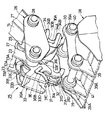
11は上部旋回体2に設けられた作業装置で、該作業装置11は、旋回フレーム3に俯仰動可能に設けられたロアブーム12と、該ロアブーム12の先端部に左,右方向に揺動可能に取付けられたアッパブーム13と、該アッパブーム13の先端部に左,右方向に揺動可能に取付けられたアームリテーナ14と、該アームリテーナ14に俯仰動可能に設けられたアーム15と、該アーム15の先端に回動可能に取付けられた後述の作業具連結装置25およびバケット38とによって大略構成されている。
【0037】
また、ロアブーム12の先端部とアームリテーナ14との間にはリンクロッド16が回動可能に連結され、該リンクロッド16は、ロアブーム12、アッパブーム13、アームリテーナ14と共に平行リンクを形成し、この平行リンクによりロアブーム12に対してアーム15(アームリテーナ14)を常時平行状態に保持している。
【0038】
さらに、旋回フレーム3とロアブーム12との間にはブームシリンダ17が設けられ、アームリテーナ14とアーム15との間にはアームシリンダ18が設けられ、アーム15と作業具連結装置25(バケット38)との間にはバケットシリンダ19が設けられている。また、ロアブーム12とアッパブーム13との間にはオフセットシリンダ20が設けられている。
【0039】
21,21はアーム15の先端側に該アーム15を左,右から挟むように設けられた左,右一対のアームリンク(左側のみ図示)で、該アームリンク21は、図2に示すように、基端側が連結ピン22を介してアーム15に回動可能に取付けられている。
【0040】
23,23はアームリンク21の先端側に挟まれるように設けられた左,右一対の中継リンクで、該左,右の中継リンク23,23は連結板23Aによって一体的に固着されている。また、中継リンク23は、基端側がアームリンク21の先端側とバケットシリンダ19のロッド先端に連結ピン24を介して回動可能に取付けられている。
【0041】
25はアーム15の先端部に回動可能に取付けられた本実施の形態による作業具連結手段としての作業具連結装置で、該作業具連結装置25は、図3に示す如く、後述するフック支持体26、固定フック30、回動フック31、ラッチ板33、板ばね34,36、固定ピン37等によって大略構成されている。
【0042】
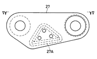
26はフック支持体で、該フック支持体26は、アーム15の先端部を挟むように配設された左,右一対の側板27,27と、該各側板27の基端側に設けられ、該各側板27をアーム15に回動可能に連結した連結ピン28と、前記各側板27の先端側に設けられた連結ピン29とによって大略構成されている。
【0043】
ここで、各側板27のうち、左側の側板27は、図4、図5に示すように、長円状の板体からなり、その長さ方向の中間部には、後述の固定フック30が取付けられる取付座27Aが形成されている。なお、右側の側板27は左側の側板27と対称形状となっているだけなのでその説明を省略する。さらに、各側板27の先端側に設けられた連結ピン29には、中継リンク23の先端部と、後述の回動フック31、ラッチ板33とが取付けられている。
【0044】
30はフック支持体26の各側板27間に取付けられた固定フックで、該固定フック30は、図6、図7に示す如く、基端側が各側板27の取付座27A間にボルト止めされ、先端側が斜め下側に伸びた左,右一対の板体30A,30Aと、該各板体30Aの先端側にそれぞれ形成された切欠開口30B,30Bとによって構成されている。ここで、各切欠開口30Bは、後述する第2の取付ピン41と反対側に向けて開口し、第1の取付ピン40に外周側から係合するものである。
【0045】
31はフック支持体26の先端側に設けられた回動フックで、該回動フック31は、図8、図9に示す如く、ほぼ長円状に形成された左,右一対の板体31A,31Aと、該各板体31Aの基端側に位置して該各板体31Aを連結した連結筒体31Bと、前記各板体31Aの先端側に固着された固定板31Cとによって大略構成されている。また、各板体31Aの先端側には、回動フック31が揺動(回動)することにより第1の取付ピン40と反対側から第2の取付ピン41に係合する切欠開口31Dが形成されている。さらに、各板体31Aの長さ方向中間部には、後述の固定ピン37が挿通するピン穴31Eが穿設されている。また、固定板31Cには、後述のラッチ板33を第2の取付ピン41から離脱させるための離脱用ボルト32が上向きに螺着されている。
【0046】
このように構成された回動フック31は、図3に示すように、その基端側がフック支持体26の先端側に設けられた連結ピン29の中央部分に回動可能に取付けられている。これにより、回動フック31は、フック支持体26(固定フック30)に対する回動角度を調整することにより、固定フック30の切欠開口30Bと該回動フック31の切欠開口31Dとの離間寸法を変更することができ、作業具として用いられる他のバケット、ブレーカ、タンパ(いずれも図示せず)毎に異なる取付ピン間の距離に対応することができる。
【0047】
33は回動フック31を挟むように配設された抜止め部材としてのラッチ板で、該ラッチ板33は、図10、図11に示す如く、回動フック31の各板体31Aに対面して配設された左,右の板体33A,33Aと、該各板体33Aを連結するように前方に張出した連結板33Bとによって大略構成されている。また、各板体33Aの基端側には、第2の取付ピン41に対する係合方向、即ち長さ方向に長穴状となったガイド穴33Cが形成され、ラッチ板33は該ガイド穴33Cによって連結ピン29の軸線と直交する方向にスライド可能となっている。また、各板体33Aの先端側には、第2の取付ピン41に係合する切欠開口33Dが形成されている。さらに、各板体33Aの長さ方向中間部には、回動フック31のピン穴31Eに対応する位置にピン穴33Eが穿設されている。
【0048】
ここで、ラッチ板33は、ガイド穴33Cを介してフック支持体26の連結ピン29に移動可能、即ち、連結ピン29に取付けられた回動フック31と相対移動可能となっている。そして、回動フック31の切欠開口31Dは、連結ピン29を中心として揺動しながら第2の取付ピン41に係合するのに対し、ラッチ板33の切欠開口33Dは、ガイド穴33Cに沿って移動(スライド)しながら第2の連結ピン41に係合するように形成されている。これにより、ラッチ板33は、第2の取付ピン41に切欠開口33Dを係合することによって回動フック31の切欠開口31Dが取付ピン41から離脱するのを後述の固定ピン37と共に防止することができる。
【0049】
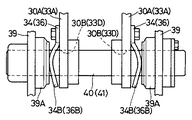
34,34は固定フック30の各板体30A外面に位置して切欠開口30Bの近傍に交換可能に取付けられた弾性体としての左,右一対の板ばねで、該各板ばね34は、板体30Aにボルト35,35を介して取付けられた長方形状の取付部34Aと、該取付部34Aの両端側から切欠開口30Bに沿って湾曲して伸びたばね部34B,34Bとによって構成されている。
【0050】
そして、板ばね34は、図14に示すように、自由状態においてばね部34Bが後述するバケット38に設けられたブラケット39,39間の離間寸法(第1の取付ピン40の有効長さ寸法)L1 よりも大きく張出した全体幅寸法L2 を有している。ここで、例えば板ばね34には、前述した全体幅寸法が小さくなるように撓み量が小さく形成された板ばね、大きくなるように撓み量が大きく形成された板ばね等の他の板ばねが用意され、これらの板ばねは、他の作業具に設けられたブラケット間の離間寸法に応じて適宜交換して用いられる。
【0051】
これにより、各板ばね34は、図15に示すように、固定フック30をバケット38の取付ピン40に係合させたときには、ブラケット39に設けられたボス部39Aの内端面に弾性的に当接し、該ブラケット39と固定フック30との間の隙間を埋め、バケット38が取付ピン40の軸方向にがたつくのを防止することができる。
【0052】
また、36,36はラッチ板33の各板体33A外面に位置して切欠開口33Dの近傍に交換可能に取付けられた弾性体としての左,右の板ばねで、該各板ばね36は、固定フック30側の板ばね34とほぼ同様に、板体33Aにボルト35,35を介して取付けられた長方形状の取付部36Aと、該取付部36Aの一方の端部から切欠開口33Dに沿って湾曲して伸びたばね部36Bとによって構成されている。そして、板ばね36は、自由状態においてばね部36Bがバケット38の各ブラケット39間寸法(第2の取付ピン41の有効長さ寸法)L3 よりも大きく張出した全体幅寸法L4 を有している。ここで、例えば板ばね36には、前記板ばね34と同様に、全体幅寸法が異なるように撓み量が設定された他の板ばねが用意され、適宜交換して用いられる。
【0053】
これにより、各板ばね36は、板ばね34と同様に、ラッチ板33をバケット38の取付ピン41に係合させたときには、ブラケット39に設けられたボス部39Aの内端面に弾性的に当接し、バケット38ががたつくのを防止することができる。
【0054】
37は回動フック31とラッチ板33との間に設けられた固定部材としての固定ピンで、該固定ピン37は、第2の取付ピン41に対し回動フック31とラッチ板33の両方が係合した状態で、それぞれのピン穴31E,33Eに亘って挿通され、両者を一体的に固定するものである。
【0055】
一方、38は作業具連結装置25に着脱可能に取付けられる作業具の一つを構成するバックホウ式のバケットで、該バケット38は、図1に示す如く、U字状に折曲げられた底板と左,右の側板とによって前方に開口し、開口側の先端部には複数の爪部が設けられている。また、バケット38の基端側には左,右のブラケット39,39が設けられ、該各ブラケット39の開口側寄りには、ボス部39A,39Aを介して第1の取付ピン40が取付けられ、後部側にはボス部39A,39Aを介して第2の取付ピン41がほぼ平行に取付けられている。
【0056】
本実施の形態による油圧ショベルは上述の如き構成を有するもので、次に、本実施の形態の特徴部分である作業具連結装置25を用いたバケット38の着脱作業について図12ないし図17を参照して説明する。
【0057】
まず、作業具連結装置25にバケット38を取付ける場合には、図12に示す如く、バケット38をブラケット39が上側となるように配置し、この状態でロアブーム12、アーム15等を操作して作業具連結装置25をバケット38に近付ける。
【0058】
そして、図13に示すように、固定フック30に設けられた切欠開口30Bをバケット38の第1の取付ピン40に外周側から径方向に係合する。このときには、図15に示すように、板体30Aに設けられた板ばね34がブラケット39のボス部39A端面に弾性的に当接するから、固定フック30に対してバケット38ががたつくのを防止することができる。
【0059】
次に、第1の取付ピン40に固定フック30を係合させたら、図16に示すように、回動フック31を第2の取付ピン41に向けて回動し、該取付ピン41に切欠開口31Dを径方向の横側から係合する。
【0060】
また、第2の取付ピン41に回動フック31の切欠開口31Dを係合させたら、図17に示すように、ラッチ板33を下向きにスライドさせ、第2の取付ピン41に切欠開口33Dに上側から係合させる。このときには、固定フック30に設けられた板ばね34と同様に、ラッチ板33に設けられた板ばね36がブラケット39のボス部39A端面に弾性的に当接するから、ラッチ板33(回動フック31)とバケット38との隙間を埋め、該バケット38ががたつくのを防止することができる。
【0061】
そして、第2の取付ピン41に回動フック31とラッチ板33とを係合させたら、該回動フック31とラッチ板33とに亘って固定ピン37を取付けることにより、両者を一体的に固定することができる。
【0062】
このようにして、第1の取付ピン40に固定フック30を係合し、第2の取付ピン41に回動フック31とラッチ板33を係合することにより、固定フック30、回動フック31、バケット38(ブラケット39)等によってピン29,40,41を結ぶ三角形を形成することができる。従って、作業具連結装置25は、この三角形による支持でバケット38を確実に支持することができる。
【0063】
一方、作業具連結装置25からバケット38を取外す場合には、前述した取付作業と逆の作業を行なうことにより取外すことができる。このバケット38の取外し作業では、第2の取付ピン41からラッチ板33を取外すときに、離脱用ボルト32をねじ込んでラッチ板33の連結板33Bを上側に押圧することにより、該ラッチ板33を容易に取外すことができる。
【0064】
かくして、本実施の形態によれば、作業具連結装置25にバケット38を取付ける場合に、第1の従来技術で述べたように別途油圧シリンダ等の動力源を設ける必要がないから、作業具連結装置25の構成を簡略化することができ、組立作業性の向上、コストの低減等を図ることができる。
【0065】
しかも、バケット38に設けられた第1の取付ピン40に対し固定フック30を係合するとき、また第2の取付ピン41に対し回動フック31、ラッチ板33を係合するときには、各取付ピン40,41の外周側から容易に係合することができる。従って、第2の従来技術のように取付ピンを挿通するための位置合わせ作業を行なうことなく、バケット38の着脱作業を簡単に行なうことができるから、一人でバケット38の着脱作業を行なうこともできる。
【0066】
また、第1の取付ピン40に固定フック30を係合し、第2の取付ピン41に回動フック31等を係合した状態では、固定フック30、回動フック31およびバケット38によって三角形を形成することができるから、作業具連結装置25に対してバケット38等の作業具を強固に支持することができ、作業時の耐久性を高め、信頼性を向上することができる。
【0067】
一方、固定フック30に板ばね34を設け、ラッチ板33に板ばね36を設け、これらの板ばね34,36をバケット38のブラケット39にそれぞれ弾性的に押付ける構成としている。
【0068】
これにより、作業具連結装置25とバケット38との間でバケット38ががたつくような事態を防止することができ、作業性、信頼性等を向上することができる。また、板ばね34,36は作業具連結装置25に対してボルト35によって交換可能に取付けられているから、例えば撓み量の小さい板ばね、撓み量の大きい板ばねを用意し交換して用いることにより、隙間が小さい場合から大きい場合まで、広範囲に対応することができる。また、板ばね34,36がへたりを生じたり、損傷したときには、ボルト35によって容易に交換することができる。
【0069】
しかも、バケット38を、他のバケットや作業具に交換したときに、作業具毎にブラケットの間隔が異なる場合には、板ばね34,36がブラケットとの隙間に応じて撓み量を変化させ、この隙間を埋める。従って、数多くの種類の作業具をがたつくことなく確実に取付けることができ、作業具連結装置25の適用範囲を広めることができる。
【0070】
さらに、ラッチ板33は第2の取付ピン41に対する係合方向に長穴状となったガイド穴33Cを介してフック支持体26の連結ピン29に移動可能に取付ける構成としているから、ラッチ板33を回動フック31と一緒に連結ピン29を利用して取付けることができ、構成を簡略化することができる。しかも、ラッチ板33は、ガイド穴33Cにより回動フック31に対して移動可能となっているから、該ラッチ板33を第2の取付ピン41に容易に係合、離脱することができる。
【0071】
なお、実施の形態では、作業具連結装置25は、バケット38の第1の取付ピン40に固定フック30を係合し、第2の取付ピン41に回動フック31とラッチ板33を係合した場合を例に挙げて説明したが、本発明はこれに限るものではなく、例えば図18に示す変形例による作業具連結装置25′のように、固定フック30′を第2の取付ピン41に係合し、回動フック31′とラッチ板33′を第1の取付ピン40に係合する構成としてもよい。
【0072】
また、実施の形態では、板ばね34は、長方形状の取付部34Aと該取付部34Aから伸びたばね部34B,34Bとによって構成し、板ばね36は、長方形状の取付部36Aと該取付部36Aから伸びたばね部36Bとによって構成した場合を例示したが、本発明はこれに限らず、例えば、板ばね34,36は複数枚の板ばねを重ね合わせることによりリーフスプリングとして形成してもよい。この場合には、重ね合わせるばね板の枚数を調整することにより、撓み量を容易に変更することができる。
【0073】
また、実施の形態では、作業具連結装置25に作業具としてバックホウ式のバケット38を着脱する場合を例に挙げて説明したが、本発明はこれに限らず、例えば作業具連結装置25にブレーカ、タンパ等からなる他の作業具をバケット38に代えて取付ける構成としてもよい。
【0074】
さらに、実施の形態では、履帯を有する下部走行体1を備えた油圧ショベルを例示したが、これに替えて、ホイール式の油圧ショベル等の他の建設機械に適用してもよい。
【0075】
【発明の効果】
以上詳述した通り、請求項1の発明によれば、作業具連結手段は、アームの先端側に取付けられるフック支持体と、該フック支持体に固定して設けられ作業具の第1,第2の取付ピンのうち一方の取付ピンに係合する固定フックと、前記フック支持体に回動可能に設けられ他方の取付ピンに係合する回動フックと、該回動フックに対して相対移動可能に設けられ該回動フックと一緒に他方の取付ピンに係合することにより回動フックの抜止めを行なう抜止め部材とにより構成し、前記回動フックは、基端側を前記フック支持体に設けられた連結ピンに回動可能に取付けると共に先端側に他方の取付ピンに係合する切欠開口を設ける構成とし、前記抜止め部材は、基端側を前記連結ピンの径方向にスライド可能に取付けると共に先端側に他方の取付ピンに係合する切欠開口を設ける構成としている。
【0076】
従って、第1,第2の取付ピンのうち、一方の取付ピンに外周側から固定フックを係合し、この状態で回動フックを揺動しつつ外周側から他方の取付ピンに係合し、続いて抜止め部材を他の取付ピンに外周側から係合することによって、作業具連結手段と作業具との間には、固定フック、回動フック、作業具等によって三角形を形成することができる。これにより、作業具連結手段に対して作業具を強固に支持することができ、信頼性を向上することができる。しかも、固定フック、回動フックおよび抜止め部材は、いずれも取付ピンに外周側から係合する構成としているから、これらを取付ピンに対して容易に係合、離脱することができ、作業具を着脱するときの作業性を向上することができる。
【0077】
そして、前記回動フックは、基端側をフック支持体に設けられた連結ピンに回動可能に取付けると共に先端側に他方の取付ピンに係合する切欠開口を設ける構成とし、抜止め部材は、基端側を前記連結ピンの径方向にスライド可能に取付けると共に先端側に他方の取付ピンに係合する切欠開口を設ける構成としているので、回動フックを作業具の他方の取付ピンに近付けた状態で、該回動フックが回動(揺動)することにより、その切欠開口は他方の取付ピンに外周側から容易に係合することができる。また、抜止め部材が連結ピンの径方向にスライドすることにより、その切欠開口は他方の取付ピンに容易に係合することができる。これらのことにより、作業具連結手段に対する作業具の着脱作業を容易に行なうことができる。
【0078】
一方、請求項2の発明によると、作業具連結手段は、アームの先端側に取付けられるフック支持体と、該フック支持体に固定して設けられ作業具の第1,第2の取付ピンのうち一方の取付ピンに係合する固定フックと、前記フック支持体に回動可能に設けられ他方の取付ピンに係合する回動フックと、該回動フックに対して相対移動可能に設けられ該回動フックと一緒に他方の取付ピンに係合することによって回動フックの抜止めを行なう抜止め部材とにより構成し、前記フック支持体には前記回動フックを回動可能に支持する連結ピンを設け、前記抜止め部材には該連結ピンが挿通される長穴状のガイド穴を設け、前記抜止め部材は、回動フックに対し該ガイド穴に沿って相対移動することにより前記他方の取付ピンに係合するラッチ板により構成しているので、請求項1の発明と同様に、作業具連結手段と作業具との間には、固定フック、回動フック、作業具等によって三角形を形成することができ、作業具連結手段に対して作業具を強固に支持することができると共に、信頼性を向上することができる。しかも、固定フック、回動フックおよび抜止め部材は、いずれも取付ピンに外周側から係合する構成としているから、これらを取付ピンに対して容易に係合、離脱することができ、作業具を着脱するときの作業性を向上することができる。
【0079】
そして、フック支持体には回動フックを回動可能に支持する連結ピンを設け、抜止め部材には該連結ピンが挿通される長穴状のガイド穴を設け、抜止め部材は回動フックに対し該ガイド穴に沿って相対移動することにより他方の取付ピンに係合するラッチ板により構成しているので、ラッチ板はフック支持体の連結ピンに回動フックと一緒に取付けることができ、これらの取付構造を簡略化することができる。しかも、ラッチ板は、長穴状のガイド穴によって回動フックに対して移動可能となっているから、他方の取付ピンに係合、離脱することができ、作業具の着脱作業を容易に行なうことができる。
【0080】
請求項3の発明によれば、回動フックと抜止め部材との間には、該回動フックと抜止め部材を他方の取付ピンに係合させた状態で両者を一体的に固定する固定部材を設けているので、固定部材は、作業時等に抜止め部材が他方の取付ピンから離脱するのを防止することができ、信頼性を高めることができる。
【0081】
請求項4の発明によれば、固定フックには、該固定フックを作業具の一方の取付ピンに係合させたときに作業具のブラケットに対して弾性的に当接する弾性体を設けているので、取付ピンを支持しているブラケットと固定フックとの間に隙間がある場合でも、弾性体によってブラケットと固定フックとの間の隙間を埋めてがたつきを抑えることができ、作業性、信頼性等を向上することができる。
【0082】
請求項5の発明によれば、抜止め部材には、該抜止め部材を作業具の他方の取付ピンに係合させたときに作業具のブラケットに対して弾性的に当接する弾性体を設けているので、取付ピンを支持しているブラケットと抜止め部材との間に隙間がある場合でも、弾性体は、ブラケットと抜止め部材との間の隙間を埋めてがたつきを抑えることができ、作業性、信頼性等を向上することができる。
【0083】
請求項6の発明によれば、弾性体は作業具連結手段のフックに取付けられた板ばねにより構成しているので、フックを取付ピンに係合したときには、板ばねがフックとブラケットとの間の隙間に応じて撓むから、各ブラケット間でフックががたつくのを防止することができる。
【0084】
請求項7の発明によれば、板ばねは作業具連結手段のフックに交換可能に取付ける構成としているので、例えば撓み量の小さい板ばね、撓み量の大きい板ばねを用意し、交換して用いることにより、フックとブラケットとの間の隙間が小さい場合から大きい場合まで、広範囲に対応することができる。また、板ばねがへたりを生じたり、損傷したときには、容易に交換することができる。
【図面の簡単な説明】
【図1】本発明の実施の形態による作業装置を備えた油圧ショベルを示す正面図である。
【図2】図1中のアーム、作業具連結装置、バケット等を示す一部破断の要部拡大図である。
【図3】作業具連結装置とバケットとを分解した状態で示す要部拡大の外観斜視図である。
【図4】フック支持体の側板を単体で示す正面図である。
【図5】図4中の矢示V−V方向からみた側板の平面図である。
【図6】固定フックを単体で示す正面図である。
【図7】図6中の矢示 VII−VII 方向からみた固定フックの右側面図である。
【図8】回動フックを単体で示す正面図である。
【図9】図8中の矢示IX−IX方向からみた回動フックの右側面図である。
【図10】ラッチ板を単体で示す正面図である。
【図11】図10中の矢示XI−XI方向からみたラッチ板の右側面図である。
【図12】作業具連結装置をバケットに近付けている状態を示す一部破断の要部拡大図である。
【図13】作業具連結装置の固定フックをバケットの第1の取付ピンに係合させた状態を示す一部破断の要部拡大図である。
【図14】固定フック(ラッチ板)を取付ピンから離脱して板ばねを自由状態で示す要部拡大図である。
【図15】固定フック(ラッチ板)を取付ピンに係合して板ばねを弾性変形させた状態を示す要部拡大図である。
【図16】作業具連結装置の固定フックをバケットの第1の取付ピンに係合させ、回動フックを第2の取付ピンに係合させた状態を示す一部破断の要部拡大図である。
【図17】作業具連結装置の固定フックをバケットの第1の取付ピンに係合させ、回動フックとラッチ板を第2の取付ピンに係合させた状態を示す一部破断の要部拡大図である。
【図18】本発明の変形例によるアーム、作業具連結装置、バケット等を示す一部破断の要部拡大図である。
【符号の説明】
1 下部走行体(車体)
2 上部旋回体(車体)
11 作業装置
12 ロアブーム
13 アッパブーム
15 アーム
25 作業具連結装置(作業具連結手段)
26 フック支持体
29 連結ピン
30 固定フック
30B,31D,33D 切欠開口
31 回動フック
33 ラッチ板(抜止め部材)
33C ガイド穴
34,36 板ばね(ばね部材)
37 固定ピン(固定部材)
38 バケット(作業具)
39 ブラケット
40 第1の取付ピン
41 第2の取付ピン[0001]
BACKGROUND OF THE INVENTION
The present invention relates to a work device for a construction machine such as a hydraulic excavator that is preferably used for civil engineering work and construction work, and more particularly to a work machine for a construction machine configured to replace and install a plurality of types of work tools. .
[0002]
[Prior art]
In general, a working device used for a construction machine such as a hydraulic excavator includes a boom that can be raised and lowered on the front side of an upper swing body, an arm that can be raised and lowered on the tip side of the boom, and a tip of the arm. A work tool such as a bucket that is rotatably provided on the side, and a hydraulic cylinder that drives the boom, the arm, and the work tool, respectively.
[0003]
Also, the excavator work device can be mounted by exchanging multiple types of buckets of different shapes and sizes, for example, buckets, breakers, tampers, etc. according to the work contents such as excavation work, collapsing work, consolidation work etc. The excavator having such a work device can perform a plurality of types of work with one vehicle.
[0004]
This type of prior art working device is known, for example, from Japanese Patent Laid-Open No. 9-209391 (hereinafter referred to as the first prior art), Japanese Patent Laid-Open No. 11-117345 (hereinafter referred to as the second prior art), and the like. ing. The work device includes a work tool connecting means on the distal end side of the arm, and the work tool has first and second mounting pins that engage with the work tool connecting means. It is configured to be detachable (replaceable) through each mounting pin.
[0005]
Here, the work tool connecting means according to the first prior art includes a bracket having a notch that engages one of the first and second mounting pins provided on the work tool, and the bracket. An arm that is swingably provided and has a notch that engages with the other pin, and is provided between the bracket and the arm. The arm is swung with respect to the bracket. It is generally configured by an opening / closing device such as a hydraulic cylinder that approaches and separates the gap from the notch.
[0006]
The work tool connecting means according to the first prior art makes the notch of the bracket and the notch of the arm approach by a hydraulic cylinder, and in this state, the bracket and the arm are connected between the first and second mounting pins of the work tool. To place. Next, the notch of the bracket and the notch of the arm are separated from each other by the hydraulic cylinder, and each notch is engaged with the mounting pin. Thereby, since the work tool connection means engages with each mounting pin of the work tool from the inside, the work tool can be detachably held.
[0007]
The work tool connecting means according to the second prior art is provided with a coupler at the tip of the arm, and the coupler is engaged with one of the first and second mounting pins provided on the work tool. A hook portion to be joined is provided integrally, and a coupler link having a pin hole through which the other attachment pin of the work tool is inserted is rotatably provided.
[0008]
According to the second prior art work tool connecting means, the hook portion provided integrally with the coupler is engaged with one mounting pin of the work tool, and the other mounting pin is connected to the bracket of the work tool and the coupler link. Insert it into the pin hole. Thereby, the work tool connecting means can be engaged with each mounting pin of the work tool and can hold the work tool in a detachable manner.
[0009]
[Problems to be solved by the invention]
By the way, in the hydraulic excavator working device according to the first prior art described in JP-A-9-209391, a hydraulic cylinder is provided between the bracket and the arm, so that the structure of the work tool connecting means is complicated. In addition, a hose or the like for driving the hydraulic cylinder is required, and there is a problem in that the work apparatus as a whole increases costs and lowers assembly workability.
[0010]
Further, in the hydraulic excavator working device according to the second prior art described in JP-A-11-117345, when the coupler link is attached to the bracket of the bucket, the pin hole and the coupler link formed in the bracket of the working tool. There is a problem in that the assembly workability is deteriorated because it is necessary to align the pin holes with each other and insert the mounting pins over these pin holes, and the alignment work takes time.
[0011]
On the other hand, when the work tool connecting means according to the first and second prior arts replaces the work tool, the distance between the first mounting pin and the second mounting pin provided on the other work tool is different. This can be dealt with by adjusting the opening dimension of the bracket and the arm by the hydraulic cylinder, or adjusting the rotation angle between the hook portion and the coupler link.
[0012]
However, when the length dimension of the mounting pin provided in the work tool, that is, the dimension between the brackets supporting both ends of the mounting pin is different, this cannot be dealt with. For this reason, even if the work tool can be attached to the work tool connecting means, depending on the work tool, a gap is formed between the bracket and the work tool connecting means. There is a problem that it causes rattling.
[0013]
The present invention has been made in view of the above-described problems of the prior art, and an object of the present invention is to allow a work tool to be attached and detached without using an actuator such as a hydraulic cylinder, and to simplify the configuration of the work tool connecting means. An object of the present invention is to provide a working device for a construction machine that can be used.
[0014]
Another object of the present invention is to provide a working device for a construction machine that allows a work tool to be replaced with a simple work without inserting or removing a mounting pin provided on the work tool. .
[0015]
Another object of the present invention is to provide a working device for a construction machine which can improve workability and reliability by preventing the work tool from rattling against the work tool connecting means. It is in.
[0016]
Furthermore, another object of the present invention is to prevent the work tool from rattling against the work tool connecting means when another work tool having a different bracket interval is connected to the work tool connecting means. It is an object of the present invention to provide a working device for a construction machine that can be used.
[0017]
[Means for Solving the Problems]
According to a first aspect of the present invention, there is provided a working apparatus for a hydraulic excavator, a boom attached to a frame of a vehicle body so as to be able to be lifted and lowered, an arm provided so as to be able to be lifted and lowered on a tip side of the boom, And a work tool that is detachably attached to the distal end side of the arm using the work tool connection means by means of first and second mounting pins provided on the bracket.
[0018]
In order to solve the above-mentioned problem, the feature of the configuration adopted by the invention of
[0019]
With this configuration, the fixing hook is engaged with one of the first and second mounting pins from the outer peripheral side, and the rotating hook is swung in this state while the other is connected from the outer peripheral side. By engaging the mounting pin and subsequently engaging the retaining member with the other mounting pin from the outer peripheral side, a fixing hook, a rotating hook, a working tool, etc. are provided between the working tool connecting means and the working tool. Therefore, the work tool can be firmly supported with respect to the work tool connecting means. In addition, since the fixed hook, the rotating hook, and the retaining member are all engaged with the mounting pin from the outer peripheral side, they can be easily engaged with and detached from the mounting pin.
In addition, the pivot hook is configured to pivotally attach the base end side to a connecting pin provided on the hook support and to provide a notch opening that engages the other attachment pin on the distal end side. Since the base end side is slidably mounted in the radial direction of the connecting pin and the notch opening that engages the other mounting pin is provided on the distal end side, the rotating hook is brought close to the other mounting pin of the work tool. In this state, when the turning hook is turned (swinged), the notch opening can be easily engaged with the other mounting pin from the outer peripheral side. Furthermore, when the retaining member slides in the radial direction of the connecting pin, the notch opening can be easily engaged with the other mounting pin.
[0020]
on the other hand,Invention of Claim 2The working tool connecting means includes a hook support attached to the distal end side of the arm and one of the first and second attachment pins of the work tool provided fixed to the hook support. A fixed hook that engages with the mounting pin, a rotating hook that is pivotally provided on the hook support and engages with the other mounting pin, and that is provided so as to be relatively movable with respect to the rotating hook. A connecting pin that includes a moving hook and a retaining member for retaining the rotating hook by engaging with the other mounting pin, and the hook supporting member rotatably supports the rotating hook. The retaining member is provided with an elongate guide hole through which the connecting pin is inserted, and the retaining member moves relative to the rotating hook along the guide hole, thereby A latch plate that engages the mounting pin. ToothThat is.
[0021]
With this configuration,As in the first aspect of the invention, a triangle can be formed between the work tool connecting means and the work tool by a fixing hook, a rotating hook, a work tool, and the like. Can be firmly supported. Moreover, fixed hooks, rotating hooks and retaining members ( Since all of the latch plates are configured to engage with the mounting pins from the outer peripheral side, they can be easily engaged with and detached from the mounting pins. The latch plate can be attached to the connecting pin of the hook support together with the rotating hook. Furthermore, since the latch plate can be moved with respect to the rotating hook by the elongated hole-shaped guide hole, it can be moved along the guide hole, and is engaged with and detached from the other mounting pin.can do.
[0022]
According to the invention of claim 3,Between the rotating hook and the retaining member, a fixing member that integrally fixes the rotating hook and the retaining member with the other mounting pin engaged.It is in having established.
[0023]
With this configuration,Since the fixing member can integrally fix both of the rotating hook and the retaining member with the other mounting pin, the retaining member is detached from the other mounting pin when working or the like. PreventCan.
[0024]
According to the invention of claim 4,Fixing hookIn theFixing hookThe work implementoneAnd an elastic body that elastically abuts against the bracket of the work tool when engaged with the other mounting pin.
[0025]
With this configuration, the bracket supporting the mounting pin andFixing hookEven if there is a gap betweenFixing hookThe work implementoneElastically abuts the work implement bracket when mounted on the other mounting pinShiThe bracket andFixing hookThe gap between them can be filled and rattling can be suppressed.
[0026]
According to the invention of
[0027]
With this configuration,Even when there is a gap between the bracket that supports the mounting pin and the retaining member, the elastic body elastically attaches to the bracket of the work tool when the retaining member is attached to the other mounting pin of the work tool. Since it abuts, it fills the gap between the bracket and the retaining member to reduce rattling.Can.
[0032]
Claim6According to the invention, the elastic body is constituted by a leaf spring attached to the hook of the work tool connecting means. Accordingly, when the hook is engaged with the mounting pin, the leaf spring is bent (elastically deformed) according to the gap between the hook and the bracket, and the hook is prevented from rattling between the brackets.
[0033]
Claim7According to the invention, the leaf spring is configured to be exchangeably attached to the hook of the work tool connecting means. Thus, for example, a leaf spring with a small amount of deflection and a leaf spring with a large amount of deflection are prepared.,By exchanging and usingWhatIt is possible to deal with a wide range from a small gap to a large gap between the hook and the bracket. Further, when the leaf spring is sagged or damaged, it can be easily replaced.
[0034]
DETAILED DESCRIPTION OF THE INVENTION
Hereinafter, a working device for a hydraulic excavator provided with a backhoe-type bucket will be described as an example of a working device for a construction machine according to an embodiment of the present invention, and will be described in detail with reference to FIGS.
[0035]
[0036]
[0037]
A
[0038]
Further, a boom cylinder 17 is provided between the revolving frame 3 and the
[0039]
21 and 21 are a pair of left and right arm links (only the left side is shown) provided on the distal end side of the
[0040]
[0041]
[0042]
[0043]
Here, among the
[0044]
[0045]
[0046]
As shown in FIG. 3, the
[0047]
[0048]
Here, the
[0049]
[0050]
As shown in FIG. 14, the
[0051]
Accordingly, as shown in FIG. 15, each
[0052]
[0053]
As a result, each
[0054]
Reference numeral 37 denotes a fixing pin as a fixing member provided between the
[0055]
On the other hand, 38 is a backhoe-type bucket that constitutes one of the work tools that are detachably attached to the work
[0056]
The hydraulic excavator according to the present embodiment has the above-described configuration. Next, with reference to FIGS. To explain.
[0057]
First, when attaching the
[0058]
Then, as shown in FIG. 13, the
[0059]
Next, when the fixing
[0060]
When the
[0061]
Then, when the
[0062]
In this way, the fixed
[0063]
On the other hand, when removing the
[0064]
Thus, according to the present embodiment, when attaching the
[0065]
In addition, when the fixed
[0066]
When the fixed
[0067]
On the other hand, a
[0068]
Thereby, the situation where the
[0069]
Moreover, when the
[0070]
Further, the
[0071]
In the embodiment, the work
[0072]
In the embodiment, the
[0073]
In the embodiment, the case where the backhoe-
[0074]
Furthermore, in the embodiment, the hydraulic excavator provided with the
[0075]
【The invention's effect】
As described above in detail, according to the invention of
[0076]
Accordingly, of the first and second mounting pins, the fixing hook is engaged with one of the mounting pins from the outer peripheral side, and the rotating hook is swung in this state and the other mounting pin is engaged from the outer peripheral side. Subsequently, by engaging the retaining member with another mounting pin from the outer peripheral side, a triangle is formed between the work tool connecting means and the work tool by a fixing hook, a rotating hook, a work tool, etc. Can. ThisThe work tool can be firmly supported with respect to the work tool connecting means, and the reliability can be improved. In addition, since the fixed hook, the rotation hook, and the retaining member are all engaged with the mounting pin from the outer peripheral side, they can be easily engaged with and detached from the mounting pin. Workability when attaching and detaching can be improved.
[0077]
The pivot hook is configured to pivotally attach a proximal end side to a connecting pin provided on the hook support and to provide a notch opening on the distal end side to engage with the other mounting pin. Since the base end side is slidably mounted in the radial direction of the connecting pin and the notch opening for engaging the other mounting pin is provided on the distal end side, the rotating hook is brought close to the other mounting pin of the work tool. In this state, when the turning hook is turned (swinged), the notch opening can be easily engaged with the other mounting pin from the outer peripheral side. In addition, since the retaining member slides in the radial direction of the connecting pin, the notch opening can be easily engaged with the other mounting pin. Thus, the work tool can be easily attached to and detached from the work tool connecting means.be able to.
[0078]
on the other hand,Claim2According to the inventionThen, the work tool connecting means is connected to one of the first and second mounting pins of the work tool, which is fixed to the hook support body attached to the tip end side of the arm and fixed to the hook support body. A fixed hook to be coupled, a pivot hook provided on the hook support so as to be pivotable and engaged with the other mounting pin, and a pivot hook provided relative to the pivot hook. A retaining member for retaining the rotating hook by engaging with the other mounting pin, and the hook support body is provided with a connecting pin for rotatably supporting the rotating hook, The stopper member is provided with a long hole-shaped guide hole through which the connecting pin is inserted, and the retaining member is engaged with the other mounting pin by moving relative to the rotating hook along the guide hole. The latch plate Similarly to the invention of
[0079]
The hook support body is provided with a connecting pin that rotatably supports the rotating hook, and the retaining member is provided with an elongated guide hole through which the connecting pin is inserted, and the retaining member is the rotating hook. The latch plate is configured to be engaged with the other mounting pin by moving relative to the guide hole, so that the latch plate can be attached to the connecting pin of the hook support body together with the rotating hook. These mounting structures can be simplified. In addition, since the latch plate is movable with respect to the rotating hook by the elongated hole-shaped guide hole, it can be engaged with and detached from the other mounting pin, and the work tool can be easily attached and detached.be able to.
[0080]
Claim3According to the invention, the rotating hookA fixing member is provided between the rotating hook and the retaining member so as to integrally fix the rotating hook and the retaining member while being engaged with the other mounting pin.BecauseThe fixing member can prevent the retaining member from detaching from the other mounting pin at the time of work or the like, and improves the reliability.be able to.
[0081]
Claim4According to the invention ofThe fixed hook is provided with an elastic body that elastically contacts the bracket of the work tool when the fixed hook is engaged with one mounting pin of the work tool.BecauseEven if there is a gap between the bracket that supports the mounting pin and the fixed hook, the elastic body can fill the gap between the bracket and the fixed hook to reduce rattling, thus improving workability and reliability. Etc.be able to.
[0082]
Claim5According to the invention ofThe retaining member is attached to the retaining member.Work implementThe otherEngage with mounting pinLetWhenWork implementSince an elastic body that elastically contacts the bracket is provided,Even if there is a gap between the bracket supporting the mounting pin and the retaining member,Elastic body and bracketRetaining memberGap betweenCan improve the workability, reliability, etc.Can.
[0083]
Claim6According to the invention, since the elastic body is constituted by the leaf spring attached to the hook of the work tool connecting means, when the hook is engaged with the attachment pin, the leaf spring is placed in the gap between the hook and the bracket. Because it bends according to the hook between each bracketButIt is possible to prevent rattling.
[0084]
Claim7According to the invention, the leaf spring is configured to be exchangeably attached to the hook of the work tool coupling means. For example, a leaf spring having a small deflection amount and a leaf spring having a large deflection amount are prepared.,By using it by exchanging it, it is possible to deal with a wide range from a small gap to a large gap between the hook and the bracket. Further, when the leaf spring is sagged or damaged, it can be easily replaced.
[Brief description of the drawings]
FIG. 1 is a front view showing a hydraulic excavator provided with a working device according to an embodiment of the present invention.
FIG. 2 is an enlarged view of a main part of the partially broken portion showing the arm, the work tool coupling device, the bucket and the like in FIG.
FIG. 3 is an external perspective view of an enlarged main part shown in a state in which the work tool coupling device and the bucket are disassembled.
FIG. 4 is a front view showing a side plate of a hook support body alone.
5 is a plan view of a side plate as seen from the direction of arrows VV in FIG. 4;
FIG. 6 is a front view showing a single fixing hook.
7 is a right side view of the fixing hook as seen from the direction of arrows VII-VII in FIG. 6. FIG.
FIG. 8 is a front view showing a single rotation hook.
9 is a right side view of the rotating hook as seen from the direction of arrows IX-IX in FIG.
FIG. 10 is a front view showing a single latch plate.
11 is a right side view of the latch plate as viewed from the direction of arrows XI-XI in FIG.
FIG. 12 is an enlarged view of a main part of a partially broken view showing a state in which the work tool coupling device is approaching the bucket.
FIG. 13 is an enlarged view of a principal part of a partially broken view showing a state in which the fixing hook of the work tool coupling device is engaged with the first mounting pin of the bucket.
FIG. 14 is an enlarged view of an essential part showing the leaf spring in a free state by detaching the fixing hook (latch plate) from the mounting pin.
FIG. 15 is a main part enlarged view showing a state in which a fixed spring (latch plate) is engaged with a mounting pin and a leaf spring is elastically deformed.
FIG. 16 is an enlarged view of a principal part of a partially broken view showing a state in which the fixing hook of the work tool coupling device is engaged with the first attachment pin of the bucket and the rotation hook is engaged with the second attachment pin. is there.
FIG. 17 is a partially broken main portion showing a state in which the fixing hook of the work tool coupling device is engaged with the first mounting pin of the bucket, and the rotating hook and the latch plate are engaged with the second mounting pin. It is an enlarged view.
FIG. 18 is an enlarged view of a main part of a partially broken view showing an arm, a work tool coupling device, a bucket and the like according to a modification of the present invention.
[Explanation of symbols]
1 Lower traveling body (car body)
2 Upper swing body (car body)
11 Working device
12 Lower boom
13 Upper boom
15 arms
25 Work tool connecting device (work tool connecting means)
26 Hook support
29 Connecting pin
30 Fixed hook
30B, 31D, 33D Notch opening
31 Rotating hook
33 Latch plate (prevention member)
33C Guide hole
34, 36 Leaf spring (spring member)
37 Fixing pin (fixing member)
38 bucket (work implement)
39 Bracket
40 First mounting pin
41 Second mounting pin
Claims (7)
前記作業具連結手段は、前記アームの先端側に取付けられるフック支持体と、該フック支持体に固定して設けられ前記作業具の第1,第2の取付ピンのうち一方の取付ピンに係合する固定フックと、前記フック支持体に回動可能に設けられ他方の取付ピンに係合する回動フックと、該回動フックに対して相対移動可能に設けられ該回動フックと一緒に他方の取付ピンに係合することにより回動フックの抜止めを行なう抜止め部材とにより構成し、
前記回動フックは、基端側を前記フック支持体に設けられた連結ピンに回動可能に取付けると共に先端側に他方の取付ピンに係合する切欠開口を設ける構成とし、前記抜止め部材は、基端側を前記連結ピンの径方向にスライド可能に取付けると共に先端側に他方の取付ピンに係合する切欠開口を設ける構成としたことを特徴とする建設機械の作業装置。A boom mounted on the frame of the vehicle body so as to be able to be lifted and lowered, an arm provided so as to be able to be lifted and lowered on the tip side of the boom, a work tool connecting means provided on the tip side of the arm, and a bracket. In the working device of the construction machine configured by the work tool detachably attached to the distal end side of the arm using the work tool connecting means by the first and second mounting pins,
The implement coupling means includes a hook support attached et is Ru distally of the arm, first the working tool is provided fixed to the hook support, one of the mounting pins of the second attachment pin A fixed hook that engages with the hook support, a rotary hook that is rotatably provided on the hook support and engages with the other mounting pin, and a rotary hook that is provided so as to be relatively movable with respect to the rotary hook, It is constituted by a retaining member for retaining the rotating hook by engaging the other mounting pin together ,
The rotating hook is configured to pivotally attach a proximal end side to a connecting pin provided on the hook support and to provide a notch opening on the distal end side to engage with the other mounting pin, and the retaining member is A construction machine working apparatus characterized in that the base end side is slidably mounted in the radial direction of the connecting pin and a notch opening is provided on the distal end side to engage with the other mounting pin .
前記作業具連結手段は、前記アームの先端側に取付けられるフック支持体と、該フック支持体に固定して設けられ前記作業具の第1,第2の取付ピンのうち一方の取付ピンに係合する固定フックと、前記フック支持体に回動可能に設けられ他方の取付ピンに係合する回動フックと、該回動フックに対して相対移動可能に設けられ該回動フックと一緒に他方の取付ピンに係合することによって回動フックの抜止めを行なう抜止め部材とにより構成し、The work tool connecting means is provided on a hook support attached to the tip end side of the arm and one of the first and second attachment pins of the work tool provided fixed to the hook support. A fixed hook to be coupled, a pivot hook provided on the hook support so as to be pivotable and engaged with the other mounting pin, and a pivot hook provided relative to the pivot hook, together with the pivot hook A retaining member for retaining the rotating hook by engaging the other mounting pin;
前記フック支持体には前記回動フックを回動可能に支持する連結ピンを設け、前記抜止め部材には該連結ピンが挿通される長穴状のガイド穴を設け、前記抜止め部材は、回動フックに対し該ガイド穴に沿って相対移動することにより前記他方の取付ピンに係合するラッチ板により構成したことを特徴とする建設機械の作業装置。The hook support body is provided with a connecting pin that rotatably supports the rotating hook, the retaining member is provided with a long hole-shaped guide hole through which the connecting pin is inserted, and the retaining member is A working device for a construction machine, comprising a latch plate that engages with the other mounting pin by moving relative to the rotating hook along the guide hole.
Priority Applications (1)
| Application Number | Priority Date | Filing Date | Title |
|---|---|---|---|
| JP2000117029A JP4034026B2 (en) | 2000-04-18 | 2000-04-18 | Construction equipment working equipment |
Applications Claiming Priority (1)
| Application Number | Priority Date | Filing Date | Title |
|---|---|---|---|
| JP2000117029A JP4034026B2 (en) | 2000-04-18 | 2000-04-18 | Construction equipment working equipment |
Publications (2)
| Publication Number | Publication Date |
|---|---|
| JP2001295316A JP2001295316A (en) | 2001-10-26 |
| JP4034026B2 true JP4034026B2 (en) | 2008-01-16 |
Family
ID=18628407
Family Applications (1)
| Application Number | Title | Priority Date | Filing Date |
|---|---|---|---|
| JP2000117029A Expired - Fee Related JP4034026B2 (en) | 2000-04-18 | 2000-04-18 | Construction equipment working equipment |
Country Status (1)
| Country | Link |
|---|---|
| JP (1) | JP4034026B2 (en) |
Families Citing this family (4)
| Publication number | Priority date | Publication date | Assignee | Title |
|---|---|---|---|---|
| WO2004001141A1 (en) * | 2002-06-24 | 2003-12-31 | Jrb Company, Inc. | Arm assembly for excavation apparatus and method of using same |
| JP2004107936A (en) * | 2002-09-17 | 2004-04-08 | Shin Caterpillar Mitsubishi Ltd | Attaching / detaching device for attachment |
| CA3156755A1 (en) * | 2019-11-01 | 2021-05-06 | David Aperahama Calvert | A packer |
| JP7397761B2 (en) * | 2020-06-11 | 2023-12-13 | 日立Geニュークリア・エナジー株式会社 | Boiling water type natural circulation furnace |
-
2000
- 2000-04-18 JP JP2000117029A patent/JP4034026B2/en not_active Expired - Fee Related
Also Published As
| Publication number | Publication date |
|---|---|
| JP2001295316A (en) | 2001-10-26 |
Similar Documents
| Publication | Publication Date | Title |
|---|---|---|
| EP2414595B1 (en) | Quick coupling device for a works machine | |
| CA2762426C (en) | Thumb with detachable body | |
| CA1307767C (en) | Work-implement adapter for front loader | |
| KR100586087B1 (en) | Simple attachment and detachable arm of construction machine | |
| JP4034026B2 (en) | Construction equipment working equipment | |
| CA2730731C (en) | Locking device for securing a backhoe attachment to a carrier lift arm | |
| US7866935B1 (en) | Manually operated coupler | |
| US6332748B1 (en) | Rotating pawl tool latch | |
| JP4688569B2 (en) | Tractor-mounted backhoe | |
| JP2005090052A (en) | bucket | |
| JP3643238B2 (en) | Construction machinery | |
| JPH1068140A (en) | Operation attachment | |
| JP2006274725A (en) | Working machine | |
| JP5372818B2 (en) | Work machine, front device of work machine, and mounting method of front device of work machine | |
| JP2006097348A (en) | Work implement mounting device | |
| JP2000192495A (en) | Mounting structure of attachment for construction work | |
| JP2005087170A (en) | Adapter device and implement-coupling device of transferable agricultural machine using the same | |
| JP3983195B2 (en) | Construction machinery attachment drive mechanism | |
| CA2289278C (en) | Rotating pawl tool latch | |
| CN120917203A (en) | Thumb device for ground engaging work tool | |
| JP2002061220A (en) | Fixing construction of bucket attaching link for construction machine | |
| JP2004124466A (en) | Working machine | |
| JPH1129955A (en) | Quick coupler | |
| KR20220168738A (en) | Excavator attachment type thumb device | |
| JPS5825003Y2 (en) | Excavation of civil engineering excavator - dual-grip multi-purpose bucket attachment |
Legal Events
| Date | Code | Title | Description |
|---|---|---|---|
| A621 | Written request for application examination |
Free format text: JAPANESE INTERMEDIATE CODE: A621 Effective date: 20050721 |
|
| A977 | Report on retrieval |
Free format text: JAPANESE INTERMEDIATE CODE: A971007 Effective date: 20070308 |
|
| A131 | Notification of reasons for refusal |
Free format text: JAPANESE INTERMEDIATE CODE: A131 Effective date: 20070417 |
|
| A521 | Written amendment |
Free format text: JAPANESE INTERMEDIATE CODE: A523 Effective date: 20070614 |
|
| TRDD | Decision of grant or rejection written | ||
| A01 | Written decision to grant a patent or to grant a registration (utility model) |
Free format text: JAPANESE INTERMEDIATE CODE: A01 Effective date: 20071023 |
|
| A61 | First payment of annual fees (during grant procedure) |
Free format text: JAPANESE INTERMEDIATE CODE: A61 Effective date: 20071024 |
|
| FPAY | Renewal fee payment (event date is renewal date of database) |
Free format text: PAYMENT UNTIL: 20101102 Year of fee payment: 3 |
|
| R150 | Certificate of patent or registration of utility model |
Free format text: JAPANESE INTERMEDIATE CODE: R150 |
|
| LAPS | Cancellation because of no payment of annual fees |