JP4032460B2 - Wheel brake hydraulic pressure control device - Google Patents
Wheel brake hydraulic pressure control device Download PDFInfo
- Publication number
- JP4032460B2 JP4032460B2 JP25252097A JP25252097A JP4032460B2 JP 4032460 B2 JP4032460 B2 JP 4032460B2 JP 25252097 A JP25252097 A JP 25252097A JP 25252097 A JP25252097 A JP 25252097A JP 4032460 B2 JP4032460 B2 JP 4032460B2
- Authority
- JP
- Japan
- Prior art keywords
- wheel brake
- connection port
- hole
- valve
- master cylinder
- Prior art date
- Legal status (The legal status is an assumption and is not a legal conclusion. Google has not performed a legal analysis and makes no representation as to the accuracy of the status listed.)
- Expired - Lifetime
Links
Images


Description
【0001】
【発明の属する技術分野】
この出願の発明は、自動車の液圧ブレーキ装置に関し、特に、ブレーキ時の車輪のロックを防止するための車輪ブレーキ液圧制御装置に関するものである。
【0002】
【従来の技術】
この種の車輪ブレーキ液圧制御装置は、マスタシリンダと車輪ブレーキとの連通を開閉制御するための電磁弁と、リザーバと、車輪ブレーキとリザーバとの連通を開閉制御するための電磁弁と、電気モータにより駆動されリザーバのブレーキ液をダンパ室とオリフィスを順次介してマスタシリンダ側に戻す戻しポンプとを主たる構成要素としており、これらの構成要素はマスタシリンダ接続口および車輪ブレーキ接続口を形成した1つのボデーに組付けられている(特開平7−267064号公報、特開平8−80827号公報参照)。
【0003】
【発明が解決しようとする課題】
マスタシリンダ接続口および車輪ブレーキ接続口は、車両への搭載作業製を良くし、ブレーキ配管内へのブレーキ液充填時における排気度を高めるため、ボデーの上部に配設されている。ダンパ室をマスタシリンダ接続口から大きく離間させて配設した従来装置は、ダンパ室とマスタシリンダ接続口との距離が長いので、ダンパ室とマスタシリンダ接続口とを連通する通路と同通路内に固定する部材にオリフィスを形成することが必要であり、コストの点での改良の余地がある。この出願の発明は、コストの点で従来装置よりも有利な車輪ブレーキ液圧制御装置を提供することを目的とする。
【0004】
【課題を解決するための手段】
この出願の請求項1に係る発明は、マスタシリンダ接続口および車輪ブレーキ接続口が設けられたボデーの内部に、前記車輪ブレーキ接続口と前記マスタシリンダ接続口との連通を開閉制御するための第1の弁、リザーバ、前記車輪ブレーキ接続口と前記リザーバとの連通を開閉制御するための第2の弁、前記リザーバのブレーキ液をダンパ室とオリフィスを順次介して前記マスタシリンダ接続口に戻すための戻しポンプが配設されている車輪ブレーキ液圧制御装置において、前記ボデーに形成された第1の孔内に前記ダンパ室が形成され、前記ボデーに形成されて前記第1の孔の側方を前記第1の孔に近接して横切っている第2の孔により前記マスタシリンダ接続口と前記第1の弁との間の通路が形成され、前記第1の孔の周面と前記第2の孔の周面との近接部を隔てる壁の最も肉薄の個所に前記オリフィスが前記第1の孔の側からポンチによって打ち抜き形成されていることを特徴とする車輪ブレーキ液圧制御装置である。
【0005】
【発明の実施の形態】
以下、この出願に係る発明の一実施形態について図を参照して説明する。
【0006】
図1は、自動車の液圧ブレーキ装置の概略構成を示す図である。図1において、ブレーキペダル11はブースタ12を介してタンデムマスタシリンダ13と連結されており、ブレーキペダル11に加えられたブレーキ操作力はブースタ12により倍加されてタンデムマスタシリンダ13に入力される。タンデムマスタシリンダ13の2つの圧力発生室のうちの一方圧力発生室は、連通管14、車輪ブレーキ液圧制御装置24、連通管15を介して前左車輪ブレーキ16に接続されるとともに連通管14、車輪ブレーキ液圧制御装置24、連通管17を介して後右車輪ブレーキ18に接続され、またタンデムマスタシリンダ13の2つの圧力発生室のうちの他方圧力発生室は、連通管19、車輪ブレーキ液圧制御装置24、連通管20を介して前右車輪ブレーキ21に接続されるとともに連通路19、車輪ブレーキ液圧制御装置24、連通管22を介して後左車輪ブレーキ23に接続される。
【0007】
車輪ブレーキ液圧制御装置24は、マスタシリンダ13と車輪ブレーキ16、18、21、22の各々と連通を開閉制御するための常開の電磁弁25、26、27、28と、車輪ブレーキ16、18の各々とリザーバ26との連通を開閉制御するための常閉の電磁弁29、30と、車輪ブレーキ16、18から電磁弁29、30を通ってリザーバ26に流入したブレーキ液をダンパ室31とオリフィス32を順次介して電磁弁25、26の上流側に戻す戻しポンプ33と、車輪ブレーキ21、23の各々とリザーバ34との連通を開閉制御するための常閉の電磁弁35、36と、車輪ブレーキ21、23から電磁弁35、36を通ってリザーバ34に流入したブレーキ液をダンパ室37とオリフィス38を順次介して電磁弁27、28の上流側に戻す戻しポンプ39と、ポンプ31、39を駆動する1個の電気モータ40を主たる構成要素としている。
【0008】
ブレーキペダル11が操作されマスタシリンダ13から車輪ブレーキ16,18,21,23に液圧が付与されている状態において、車輪ブレーキ16の液圧は電磁弁25、29のソレノイドを励磁したり励磁を止めたりすることで減圧、保持、増圧させることができ、車輪ブレーキ18の液圧は電磁弁26、30のソレノイドを励磁したり励磁を止めたりすることで減圧、保持、増圧させることができ、車輪ブレーキ21の液圧は電磁弁27、35のソレノイドを励磁したり励磁を止めたりすることで減圧、保持、増圧させることができ、車輪ブレーキ23の液圧は電磁弁28、36のソレノイドを励磁したり励磁を止めたりすることで減圧、保持、増圧させることができる。例えば、電磁弁25のソレノイドを励磁して電磁弁25を閉位置とするとともに電磁弁29のソレノイドを励磁して電磁弁29を開位置とすれば、車輪ブレーキ16のブレーキ液が電磁弁29を通ってリザーバ26に流入し、車輪ブレーキ16の液圧が減圧する。その後、電磁弁25のソレノイドの励磁を継続するとともに電磁弁29のソレノイドの励磁を止めれば、電磁弁29が閉位置となり、車輪ブレーキ16の液圧が保持となる。その後、電磁弁25のソレノイドの励磁も止めれば、電磁弁25が開位置となり、マスタシリンダ13から車輪ブレーキ16にブレーキ液が供給され、車輪ブレーキ16の液圧が増圧する。
【0009】
尚、車輪ブレーキ16,18を左右前車輪ブレーキとし、車輪ブレーキ21,23を左右後車輪ブレーキとして実施しても良く、その場合に更に車輪ブレーキ21,23の液圧を電磁弁27、39により共通制御するように変更して実施しても良い(この場合、電磁弁28、36は省略する)。
【0010】
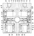
図2および図3は車輪ブレーキ液圧制御装置24の詳細構造を示す。図3は図2中の3−3線に沿う断面図である。車体に取付けられる概ね矩形のボデー41の上部には、図1の連通管14、19と夫々連通されるマスタシリンダ接続口42、43がボデー41の上面に開口するように設けられ、また図1の連通管14と連通される車輪ブレーキ接続口44がボデー41の上面に開口するように設けられているほか、図2、3には示されていないが図1の連通管17、20、22と夫々連通される3個の車輪ブレーキ接続口が設けられている。マスタシリンダ接続口42、43は図2におけるボデー41の右側面寄りに配置され、車輪ブレーキ接続口44は図2におけるボデー41の左側面寄りに配置されている。
【0011】
ボデー41の下部には上下方向の孔45、46がボデー41の下面に開口するように且つ図3の左右方向に間隔をあけて形成され、これらの孔45、46内にはピストン47、48等が収容されてリザーバ26、34が構成されている。
【0012】
ボデー41には、水平方向の弁収容孔49が車輪ブレーキ接続口44の下側に位置し且つ図2におけるボデー41の右側面に開口するように設けられている。この弁収容孔49は車輪ブレーキ接続口44に連通孔50を介して連通されるとともに連通孔51、52、53を介してマスタシリンダ接続口42に連通されている。ボデー41には、水平方向の弁収容孔54が弁収容孔49の下側に位置し且つ図2におけるボデー41の右側面に開口するように設けられている。この弁収容孔54は車輪ブレーキ接続口44に連通孔55、弁収容孔54、連通孔50を介して連通されるとともに連通孔56、57を介してリザーバ26に連通されている。弁収容孔49には図1の電磁弁25を構成する弁組立体58が収容され、弁収容孔54には図1の電磁弁29を構成する弁組立体59が収容されている。
【0013】
図2、3には示されていないが、図1の電磁弁26、27、28の弁組立体を収容する3個の弁収容孔が図2で弁収容孔49と平行に且つ図2で紙面に垂直な方向に並べて設けられており、また図1の電磁弁30、31、32の弁組立体を収容する3個の弁収容孔が図2で弁収容孔54と平行に且つ図2で紙面に垂直な方向に並べて設けられている。図1の電磁弁26の弁組立体を収容する弁収容孔は、図1の連通管17と連通される車輪ブレーキ接続口と連通されるとともに図3に示す連通孔60を介して連通孔52と連通される。図1の電磁弁27の弁組立体を収容する弁収容孔は、図1の連通管20と連通される車輪ブレーキ接続口と連通されるとともに図3に示す連通孔61、62、63を介してマスタシリンダ接続口43と連通される。図1の電磁弁28の弁組立体を収容する弁収容孔は、図1の連通管22と連通される車輪ブレーキ接続口と連通されるとともに図3に示す連通孔64を介して連通孔22と連通される。
【0014】
ボデー41には、リザーバ26、34の上側で且つリザーバ26、34の間にポンプ駆動カム軸65を収容する収容孔66(図3参照)が形成され、この収容孔66と直交する一対の収容孔67、68が形成されている。この収容孔67、68にはポンプ駆動カム軸65により駆動されるピストン69、70が収容される。これらピストン69、70は戻しポンプ33、39を構成し、電気モータ40によりポンプ駆動カム軸65が駆動されることにより、戻しポンプ33がリザーバ26のブレーキ液を連通路71を介して吸入し連通路72に吐出し、戻しポンプ39がリザーバ34のブレーキ液を連通路73を介して吸入し連通路74に吐出する。
【0015】
ボデー41には、ダンパ室31、37を形成する水平方向の孔75、76が連通路51、61の下側に形成されている。これらの孔75、76の軸線と連通路51、61の軸線とは直角であり、孔75、76と連通路51、61とを上下方向に隔てる薄い壁77、78には、オリフィス32、38が形成されている。これらオリフィスは、米国特許3271988号に記載されている如き方法により孔75、76の側からポンチによって打ち抜き形成されるものである。
【0016】
【発明の効果】
この出願の発明によれば、ダンパ室とマスタシリンダ接続口側の連通路とを薄い壁にオリフィスを穿設することによって連通するので、装置のコストを下げることができる。
【図面の簡単な説明】
【図1】自動車の液圧ブレーキ装置の概略構成を示す図である。
【図2】この出願の発明の実施形態である車輪ブレーキ液圧制御装置の詳細構造を示す断面図である。
【図3】図2中の3ー3線に沿う断面図である。
【符号の説明】
25、29・・・電磁弁
26、34・・・リザーバ
31、37・・・ダンパ室
32、38・・・オリフス
33、39・・・戻しポンプ
41・・・ボデー
42、43・・・マスタシリンダ接続口
44・・・車輪ブレーキ接続口
51、61・・・連通孔
75、76・・・孔
77、78・・・薄い壁[0001]
BACKGROUND OF THE INVENTION
The invention of this application relates to a hydraulic brake device for an automobile, and more particularly to a wheel brake hydraulic pressure control device for preventing a wheel from being locked during braking.
[0002]
[Prior art]
This type of wheel brake hydraulic pressure control device includes an electromagnetic valve for controlling the opening and closing of the communication between the master cylinder and the wheel brake, a reservoir, an electromagnetic valve for controlling the opening and closing of the communication between the wheel brake and the reservoir, The main component is a return pump that is driven by a motor and returns the brake fluid in the reservoir to the master cylinder side through the damper chamber and the orifice sequentially, and these components form a master cylinder connection port and a wheel brake connection port 1 (See Japanese Patent Application Laid-Open Nos. 7-267064 and 8-80827).
[0003]
[Problems to be solved by the invention]
The master cylinder connection port and the wheel brake connection port are arranged on the upper part of the body in order to improve the mounting work on the vehicle and increase the exhaust degree when the brake fluid is filled in the brake pipe. Since the distance between the damper chamber and the master cylinder connection port is long in the conventional device in which the damper chamber is arranged far away from the master cylinder connection port, the damper chamber and the master cylinder connection port are in the same path as the communication path. It is necessary to form an orifice in the member to be fixed, and there is room for improvement in terms of cost. It is an object of the present invention to provide a wheel brake hydraulic pressure control device that is more advantageous than conventional devices in terms of cost.
[0004]
[Means for Solving the Problems]
The invention according to claim 1 of the present application provides a first control for controlling opening and closing of communication between the wheel brake connection port and the master cylinder connection port in a body provided with a master cylinder connection port and a wheel brake connection port. 1 valve, a reservoir, a second valve for controlling opening and closing of the communication between the wheel brake connection port and the reservoir, and a brake fluid in the reservoir to return to the master cylinder connection port sequentially through a damper chamber and an orifice. in the wheel brake fluid pressure control apparatus in which the pump is disposed back of the damper chamber is formed in a first hole formed in the body, the side of the first hole is formed in the body passage between said master cylinder connecting opening said first valve is formed by a second bore which crosses proximate said first aperture, said circumferential surface and said second first hole It is the wheel brake fluid pressure control apparatus according to claim wherein said orifices in the most thin point of the wall separating the adjacent portion of the peripheral surface of the hole is punched by a punch from the side of the first hole.
[0005]
DETAILED DESCRIPTION OF THE INVENTION
Hereinafter, an embodiment of the invention according to this application will be described with reference to the drawings.
[0006]
FIG. 1 is a diagram showing a schematic configuration of a hydraulic brake device for an automobile. In FIG. 1, a
[0007]
The wheel brake hydraulic
[0008]
In a state where the
[0009]
The
[0010]
2 and 3 show the detailed structure of the wheel brake hydraulic
[0011]
In the lower part of the
[0012]
The
[0013]
Although not shown in FIGS. 2 and 3, three valve housing holes for accommodating the valve assemblies of the
[0014]
In the
[0015]
In the
[0016]
【The invention's effect】
According to the invention of this application, the damper chamber and the communication path on the master cylinder connection port side communicate with each other by drilling an orifice in a thin wall, so that the cost of the apparatus can be reduced.
[Brief description of the drawings]
FIG. 1 is a diagram showing a schematic configuration of a hydraulic brake device for an automobile.
FIG. 2 is a cross-sectional view showing a detailed structure of a wheel brake hydraulic pressure control device according to an embodiment of the invention of this application.
FIG. 3 is a cross-sectional view taken along line 3-3 in FIG.
[Explanation of symbols]
25, 29 ...
Claims (1)
Priority Applications (1)
| Application Number | Priority Date | Filing Date | Title |
|---|---|---|---|
| JP25252097A JP4032460B2 (en) | 1997-09-17 | 1997-09-17 | Wheel brake hydraulic pressure control device |
Applications Claiming Priority (1)
| Application Number | Priority Date | Filing Date | Title |
|---|---|---|---|
| JP25252097A JP4032460B2 (en) | 1997-09-17 | 1997-09-17 | Wheel brake hydraulic pressure control device |
Publications (2)
| Publication Number | Publication Date |
|---|---|
| JPH1191529A JPH1191529A (en) | 1999-04-06 |
| JP4032460B2 true JP4032460B2 (en) | 2008-01-16 |
Family
ID=17238521
Family Applications (1)
| Application Number | Title | Priority Date | Filing Date |
|---|---|---|---|
| JP25252097A Expired - Lifetime JP4032460B2 (en) | 1997-09-17 | 1997-09-17 | Wheel brake hydraulic pressure control device |
Country Status (1)
| Country | Link |
|---|---|
| JP (1) | JP4032460B2 (en) |
Families Citing this family (4)
| Publication number | Priority date | Publication date | Assignee | Title |
|---|---|---|---|---|
| DE19958194A1 (en) * | 1999-06-29 | 2001-01-04 | Continental Teves Ag & Co Ohg | Hydraulic unit |
| KR100426732B1 (en) * | 2000-04-07 | 2004-04-13 | 주식회사 만도 | Low pressure accumulator of modulator block for anti-lock brake system |
| JP4991290B2 (en) * | 2003-06-14 | 2012-08-01 | コンチネンタル・テベス・アーゲー・ウント・コンパニー・オーハーゲー | Hydraulic unit |
| DE102004030625A1 (en) * | 2003-10-10 | 2005-06-16 | Continental Teves Ag & Co. Ohg | hydraulic power unit |
-
1997
- 1997-09-17 JP JP25252097A patent/JP4032460B2/en not_active Expired - Lifetime
Also Published As
| Publication number | Publication date |
|---|---|
| JPH1191529A (en) | 1999-04-06 |
Similar Documents
| Publication | Publication Date | Title |
|---|---|---|
| EP1707463B1 (en) | Vehicle brake hydraulic pressure control unit | |
| JPH0717615Y2 (en) | Antilock modulator | |
| US8128180B2 (en) | Hydraulic brake system | |
| JP4032460B2 (en) | Wheel brake hydraulic pressure control device | |
| JPH04232165A (en) | Hydraulic type brake gear | |
| JP2005515934A (en) | Hydraulic unit for brake system with slip control | |
| KR20040007048A (en) | Anti-lock Brake System Pump Housing | |
| JP4983162B2 (en) | Brake hydraulic pressure control unit for vehicles | |
| JP2004516986A (en) | Hydraulic device for anti-slip brake system | |
| US20060125315A1 (en) | Passive pre-charge system for a vehicular brake system | |
| JPH1067310A (en) | Brake hydraulic pressure modulator for vehicle | |
| JP2001301594A (en) | Brake hydraulic pressure control device for vehicle | |
| JP2001310718A (en) | Brake hydraulic control device for vehicle | |
| JP4961911B2 (en) | Brake hydraulic pressure control unit for vehicles | |
| JP2000127935A (en) | Vehicular brake control modulator | |
| JP4778529B2 (en) | Brake hydraulic pressure control device for bar handle vehicle | |
| JPH0558260A (en) | Brake hydraulic unit | |
| JP2001225735A (en) | Anti-lick brake device | |
| JPH06263017A (en) | Braking force control device | |
| JP2001191908A (en) | Brake hydraulic pressure controller | |
| US20230131725A1 (en) | Brake apparatus for vehicle | |
| JPH11321607A (en) | Wheel break hydraulic control unit | |
| JP5491813B2 (en) | Brake hydraulic pressure control device for vehicles | |
| KR200268694Y1 (en) | Pump housing in abs system | |
| JPH08258687A (en) | Brake fluid pressure control device for vehicle |
Legal Events
| Date | Code | Title | Description |
|---|---|---|---|
| A621 | Written request for application examination |
Free format text: JAPANESE INTERMEDIATE CODE: A621 Effective date: 20040630 |
|
| A977 | Report on retrieval |
Free format text: JAPANESE INTERMEDIATE CODE: A971007 Effective date: 20060113 |
|
| A131 | Notification of reasons for refusal |
Free format text: JAPANESE INTERMEDIATE CODE: A131 Effective date: 20060124 |
|
| A521 | Written amendment |
Free format text: JAPANESE INTERMEDIATE CODE: A523 Effective date: 20060209 |
|
| A131 | Notification of reasons for refusal |
Free format text: JAPANESE INTERMEDIATE CODE: A131 Effective date: 20070227 |
|
| A521 | Written amendment |
Free format text: JAPANESE INTERMEDIATE CODE: A523 Effective date: 20070320 |
|
| TRDD | Decision of grant or rejection written | ||
| A01 | Written decision to grant a patent or to grant a registration (utility model) |
Free format text: JAPANESE INTERMEDIATE CODE: A01 Effective date: 20071002 |
|
| A61 | First payment of annual fees (during grant procedure) |
Free format text: JAPANESE INTERMEDIATE CODE: A61 Effective date: 20071015 |
|
| FPAY | Renewal fee payment (event date is renewal date of database) |
Free format text: PAYMENT UNTIL: 20101102 Year of fee payment: 3 |
|
| FPAY | Renewal fee payment (event date is renewal date of database) |
Free format text: PAYMENT UNTIL: 20101102 Year of fee payment: 3 |
|
| S111 | Request for change of ownership or part of ownership |
Free format text: JAPANESE INTERMEDIATE CODE: R313113 |
|
| FPAY | Renewal fee payment (event date is renewal date of database) |
Free format text: PAYMENT UNTIL: 20101102 Year of fee payment: 3 |
|
| R350 | Written notification of registration of transfer |
Free format text: JAPANESE INTERMEDIATE CODE: R350 |
|
| FPAY | Renewal fee payment (event date is renewal date of database) |
Free format text: PAYMENT UNTIL: 20111102 Year of fee payment: 4 |
|
| FPAY | Renewal fee payment (event date is renewal date of database) |
Free format text: PAYMENT UNTIL: 20111102 Year of fee payment: 4 |
|
| FPAY | Renewal fee payment (event date is renewal date of database) |
Free format text: PAYMENT UNTIL: 20121102 Year of fee payment: 5 |
|
| FPAY | Renewal fee payment (event date is renewal date of database) |
Free format text: PAYMENT UNTIL: 20131102 Year of fee payment: 6 |
|
| EXPY | Cancellation because of completion of term |