JP4031907B2 - Crew Oxygen Mask with Improved Wearability Adjustment Device - Google Patents
Crew Oxygen Mask with Improved Wearability Adjustment Device Download PDFInfo
- Publication number
- JP4031907B2 JP4031907B2 JP2000516736A JP2000516736A JP4031907B2 JP 4031907 B2 JP4031907 B2 JP 4031907B2 JP 2000516736 A JP2000516736 A JP 2000516736A JP 2000516736 A JP2000516736 A JP 2000516736A JP 4031907 B2 JP4031907 B2 JP 4031907B2
- Authority
- JP
- Japan
- Prior art keywords
- mask
- strap element
- strap
- user
- housing
- Prior art date
- Legal status (The legal status is an assumption and is not a legal conclusion. Google has not performed a legal analysis and makes no representation as to the accuracy of the status listed.)
- Expired - Lifetime
Links
Images


Classifications
-
- A—HUMAN NECESSITIES
- A62—LIFE-SAVING; FIRE-FIGHTING
- A62B—DEVICES, APPARATUS OR METHODS FOR LIFE-SAVING
- A62B18/00—Breathing masks or helmets, e.g. affording protection against chemical agents or for use at high altitudes or incorporating a pump or compressor for reducing the inhalation effort
- A62B18/08—Component parts for gas-masks or gas-helmets, e.g. windows, straps, speech transmitters, signal-devices
- A62B18/084—Means for fastening gas-masks to heads or helmets
Abstract
Description
【0001】
(発明の分野)
本発明は民間用または私用の航空機搭乗員が非常事態の際、一般的に使用するタイプの呼吸装置に広く関する。より具体的には、本発明は装着の際、始めは膨張し、かつ伸長することにより装着を容易にし、装着後は収縮することによりマスクが使用者の頭部にしっかり密着するよう引き寄せられる伸長可能な膨張式ストラップがマスクに結合しているフルフェースまたは部分フェースのマスクを有する呼吸装置に関し、本発明の呼吸装置はマスクが顔面を圧迫することによって生じる圧迫力(engagement force)を減らすよう調節できるようにすることにより、不快感なく装置を長時間に渡って装着するための装着感調節装置を含む。
【0002】
(従来技術の説明)
米国特許3,599,636号明細書には、呼吸装置用の膨張可能な頭部ハーネスが開示されており、前記ハーネスは加圧空気供給用の弁と接続された内部導管を有する細長い伸長可能なハーネスまたはストラップに接続されたマスクからなる。弁を開放すると、ストラップ内の導管に供給された空気がストラップを伸長させ、ある程度定まった形状とする。これにより、使用者はマスクを片手で保持し、膨張したストラップを後頭部に導くことができる。これは片手のみ使用可能な非常事態下の航空機搭乗員にとって特に有用な特徴である。
【0003】
米国特許3,599,636号明細書に開示された呼吸装置用ハーネスは、一度頭上に装着するとストラップが収縮し長さが短縮する。その後、収縮したストラップは固有の弾力性により、マスクを装着者の顔面の鼻および口部分に密着させ、それらの周辺からの吸引用ガスの漏洩を防止する。
【0004】
通常、航空機が機内高度海抜4万フィート以上を飛行する際、航空機搭乗員用マスクは肺に空気を強制的に送り込むため、加圧状況下に置かれている。そのため、このような高度での飛行時、顔面からマスクを引き離そうとする酸素の圧力に打ち勝って、マスク周縁部シールからの酸素の漏洩を防止するため、ストラップにはマスクを顔面に押し付ける方向に比較的大きなバイアス力が(biasing force)生じている必要がある。
【0005】
しかし、海抜4万フィート未満の機内では、マスク内空間を加圧呼吸状況に置く必要がなく、レギュレータは使用者の吸入という呼吸による要求によってのみ酸素富化した空気混合物が供給されるように稼動する。
【0006】
一般に、飛行時間の実質大部分は海抜4万フィート未満での飛行である。しかし、搭乗員が1名のみである場合のように常時呼吸用マスクの装着が義務付けられる状況が多々ある。したがって加圧呼吸状況が不要な低高度の場合で、呼吸装置の常時装着が義務付けられる状況ではストラップには通常、かなりのバイアス力が存在しており、ハーネスストラップはかなりの不快の原因となる。
【0007】
米国特許5,036,846号明細書には、空気圧による装着感調節機能を備えた膨張可能なハーネス型搭乗員用酸素マスクが開示されている。この膨張度合いの調節手段は、ストラップが伸長した高圧位置と収縮した低圧位置との間で、膨張式ストラップ内の圧力を調節し、維持することができる。同様に、米国特許5,623,923号および5,503,147号明細書には、使用者が快適な装着感を得ることができるよう使用時にストラップを選択的に膨張または収縮することができる膨張式ストラップの装着感調節装置が開示されている。
【0008】
これら先行例の装着感調節装置の問題は、それらの調節機構に由来する。すなわち、それらの調節方法はストラップ内の圧力状態を調節することに依存しているが、ストラップ部品に大規模な漏洩が発生した場合、装着感調節機能が操作不能になる恐れがあるという問題を有している。
【0009】
従って、呼吸装置装着時にストラップの部分的な膨張または収縮を伴うことなく、装着感を調節することが可能な膨張式呼吸装置の一部をなす改善させた装着感調節装置への需要が存在している。好ましくは、そのような改善された装着感調節装置は、ストラップが完全に収縮し、実質的に大気圧下にあるような状況においても所望の装着感調節を行えることが望ましい。
【0010】
(発明の開示)
本発明は、先に概略を述べた問題を解決し、膨張式ハーネス呼吸装置用の改善された装着感調節装置を提供する。大まかに言うと、本発明の呼吸装置は使用者の顔面に密着させるための装着面を与えるマスクを含み、マスク内に呼吸用の加圧ガスを供給するための手段を有する。マスクはさらに、マスクと機能的に結合する一対の末端部を持つ伸長可能で、かつ選択的に膨張収縮することができるストラップが取り付けられている。ストラップは膨張時、使用者の頭上に容易に装着できるよう拡大された形状となり、収縮時は使用者の頭部を締め付け、それによりマスクが使用者の顔面に密着するように引き寄せられる。装着感調節装置は使用者の顔面に対するマスクの圧迫力を減少させる。この装着感調節装置はストラップの少なくとも一つを機能的に保持し、ストラップの末端部とマスクの装着面との間で結合を保ったまま移動することが可能なマスクのマウント材よりなる。さらに、マスクの装着面に対応した選択された部位において、末端部をマウント部材に固定する止め具を有する。図示されているように、好ましい形態ではストラップが完全に収縮されている場合にそのような結合を保った状態での移動が起こる。
【0011】
好ましくは、ストラップは両方の末端部で対応するマウント部材に調節可能な状態で保持されるように取り付けられる。これにより、ストラップの片側または両側の部品が調節できる。
【0012】
取り付け部材は細長い筒状体で膨張式ストラップの末端部に固定された対応するハウジングアセンブリの内側で同軸方向に配向する様都合良い向きに固定されている。この形態において、ストラップの末端部は、末端部とマスクの装着面との間の距離を変えるため、マウントの長手方向に沿って同軸方向に調節可能である。加えて、固定された筒状マウントはストラップの膨張収縮のための手段として作用するようにマスクのレギュレータが取り付けてある。各々のハウジングアセンブリは対応するストラップ末端部に固定された細長い筒状のハウジングを含む。ハウジング内には環状で、対向している1組のシール(前部シール、後部シール)が設置されており、これらにより空洞部が仕切られている。シールのうち一方は、ハウジング内を移動可能であり、他の一方は筒状マウントに固定されている。前部シールと後部シールの間の壁面には開口部が設けられている。ストラップの膨張時、ハウジングおよびストラップ末端部は筒状ハウジングの長手方向に沿って通常位置または初期位置まで移動し、空洞部はストラップと共に加圧される。ストラップが実質的に周囲の内圧まで収縮すると、空洞部も排気される。そのうえ、ハウジングアセンブリおよびストラップに取り付けてある末端部は筒状マウントの長手方向に沿って手動で調節可能である。これはストラップの内寸法を効果的に増加させ、使用者の顔面へのマスクの装着圧を減少させる。
【0013】
他の態様において、マスクの装着面がストラップの末端部に関連して予め設定された中間位置に位置するように作用する類似の装着感調節装置が提供される。この調節機構では、ハウジングに通常時はばね入りシールで閉止されている逃し弁(放出孔)が取り付けられている。ストラップの膨張時、ハウジングの空洞部はその内圧がばね式シールを克服して加圧されたガスが空洞部から大気中へと放出され始めるまで加圧される。ストラップの収縮時、ハウジングの空洞部は加圧状態を維持する。
【0014】
(好ましい実施態様)
図面、特に図1に関して、本発明による呼吸装置10が図示されている。大まかにいって装置10は、膨張式ハーネスアセンブリ14と、使用者の顔面に対するマスクの圧迫力を軽減させる調節アセンブリ16を備えたマスク12を含む。
【0015】
より具体的には、マスク12は使用者の鼻および口を取り囲むかたちで使用者の顔面を圧迫するよう作用する装着面20を形づくる幾分弾力性のある縁部リップを形成する合成樹脂本体18を含む。マスク12にはまた、本体18の閉じ込め部に呼吸用ガス混合物を供給するために、供給されてくる加圧された呼吸用ガス(通常は酸素)を大気と混合するよう設計されたレギュレータ22も取り付けられている。本レギュレータは、参照文献として本明細書に含まれる米国特許第5,307,793号明細書に開示されているタイプのものである。ガスライン24は、図示されているように、レギュレータ22にしっかり固定され、他端は従来のガス供給源に接続される。ハーネス膨張ボタン25もまた、レギュレータ22の一部として付属している。
【0016】
ハーネスアセンブリ14は細長い筒状の膨張式ストラップ要素26を含み、ストラップ要素26は後述するようにマスク12に機能的に結合する一対の末端部28および30を有する。いくぶんU字型をしたストラップ32は、図示するようにストラップ26の反対側で結合し、装着者の頭上に広がるよう設計されている。第二のストラップ34は、ストラップ32の頂部から伸び、ストラップ26要素の後部に固定される。ストラップ要素26は、伸長可能な合成樹脂材料製であり、伸長してハーネスアセンブリを使用者の頭上に容易に装着できるよう拡大された形状をとるため選択的に膨張可能である。ストラップ要素26の収縮時、ハーネスアセンブリは収縮することで使用者の頭部を締め付け、それによってマスク、特にその装着面が使用者の顔面を圧迫する。この種のストラップ要素は、例えば参照文献として本明細書に組み入れられている米国特許4,915,106号明細書において既知である。
【0017】
装着感調節装置16は、図示するように、レギュレータ22から伸びる一対の細長い筒状の金属(アルミニウム)マウント36と、ストラップ要素26の両末端部28および30で保持されるハウジング38(図2〜図4参照)を含む。特に図2〜図4に関して、各々のアセンブリ38は 細長い筒状の金属ハウジング40を含む。ハウジング40は一体式の環状ストッパ壁46を内側に敷延すると共に、対向する前端42および後端44を与える。図示するように、対応する筒状マウント36はハウジングを長手方向に同軸状に貫いてストラップ要素26の閉じ込め部の中へと伸びる。ハウジング40の前端はストッパ壁46の前面に接する環状のDelrin座金またはブッシング48を含む。コイルばね50はブッシング48のストッパ壁46から離れた面と固定されている。三枚の独立した環状の止め具用座金52は、コイルばね50の先端とかみ合っている。図から明らかなように、ばね50および座金52は、各々筒状マウント36を滑動受けしている。しかし、止め具用座金52は、比較的中央開口部が大きく、マウント36上を限られた度合いで振動することができ、傾斜が付いた状態での固定位置となる。ピン54はエンド42近くのハウジング40の側壁を貫いて取り付けられ、最も前方に位置する止め具座金52とかみ合っており、それによりピン壁面46との間で、マウント36、止め具用座金52、ばね50およびブッシング48を保持している。
【0018】
ハウジング40の中央部には、ストッパ壁46から後方を区切っている固定したDelrinブッシング56が与えられている。図示するように、壁46とブッシング56の間には環状をした前部弾性シールが置かれている。ハウジング40の後端にはハウジング本体に固定されたDelrin後部シールを有する。シール60は、その後端に拡大された、不規則な環状の緩和区域を有し、該緩和区域は追加の環状弾性シール64を収容している。
【0019】
特にマウント36に関して、その側面に開口部を有し、さらに、その外側面に形成される隣接の緩和区域68を有する。マウント36は開口部66および緩和域68の後方にDelrinブッシング70を有し、結合器72を介してブッシング70を固定している。環状の後部弾性シール74は、緩和区域68の前側ショルダーにかみ合う形で据え付けられている。そのようにしてブッシング70およびシール74はマウント36に固定され、一斉に移動する。図2で最もよく観察されるように、空洞部75はシール58および74の間で仕切られる。
【0020】
ストラップ要素26の末端部28および30は、対応するハウジング40にクリンプフェルール76または他の手段により固定される。そのようにしてハウジング40およびそれに結合された構成部分は、ストラップ要素26に効果的に固定される。
【0021】
環状の調節ボタン78は、ハウジング40の前端に滑動固定される。特にボタン78は前端40を受けるための環状の凹部を有する。ボタンの側壁はピン54を収容するスロット82を有し、それによりボタンの移動ストロークを定めている。環状のボタン内壁84はマウント36を滑動受けし、環状の末端部86を与える。
【0022】
図1〜図4の形態の使用は、マスクが通常は搭乗員の座席隣の収納箱である準備位置に保管されていると仮定すると、以下のように進行する。収納時、ストラップ要素26の両末端部28および30は、対応するマウント36に滑動取り付けされており、止め具用の座金52を介して解除可能な状態で固定されている。使用者は始めにマスクをつかみ、減圧ボタンを押しながら保管箱から取り出す。これにより加圧された酸素がレギュレータを通して流れ、そこからマウント36へと流れる。これによりハーネス26が完全に膨張し、使用者の頭上に容易に装着することが可能な拡大された位置となる(図2〜図4参照)。しかし、これと同時に、加圧された酸素は開口部66を通って空洞部75へと流れこみ、空洞部75を加圧する。これにより,図4に見られるようにハウジング40が左側へと移動し、筒状マウント36と止め具用座金52との間の摩擦によるかみ合いは、座金が垂直の状態である解放位置に移動してハウジングが自由に移動できるようになる。この状態では、アセンブリ38は図2に示した通常位置となる。
【0023】
ストラップが膨張している状態でマスクを装着した後、使用者はボタンを放す。これによりストラップ要素内の酸素は筒状マウント36中を酸素が逆流し、レギュレータを通じて大気中へ排気されることによりストラップ要素26は中程度の収縮状態となる。このシーケンス時、空洞部75内部の酸素もまた、開口部66を介して排気される。そのため、ストラップ要素26および空洞部75は実質的に大気圧となり、図2に示すようにシール58とシール74との間の距離が広がり、ストラップ要素26はマウント36との相対関係において、マウント36がストラップ要素の閉じ込め部の中へと都合良く伸長するよう移動する。
【0024】
初期の収縮状態において、ストラップ要素は使用者の頭部に非常にしっかりと密着し、不快感を与える程度であることが好ましい。より快適な装着感を得るために使用者は図4に最もよく示されているように、その後随意に押し下げて良い。こうすることにより壁面84の末端部86が、傾いた状態になっている座金52と接するようになり、座金をマウントに対してより直交した位置へと移動させ、マウントとの摩擦によるかみ合いが解除される。さらにボタンを押し下げると、ばね50が圧縮され、ハウジング40およびストラップ要素26の末端部30を筒状マウント30の長手方向に沿って平行移動させる。これはハーネスの寸法を効果的に増加させ、すなわち末端部30と装着面との間の相対距離を変化することにより、マスク12の装着面20による顔面への圧迫力を減少させる。ボタン78を放すと、ばね50がボタンを開始時の位置に戻し、止め具用の座金52が傾斜した状態である固定位置に再び戻ることが好ましい。結果的にストラップ要素26の有効寸法は予め設定された範囲内で所望の度合いに増加させることができ、それにより使用者の顔面にかかるマスクの圧迫力を本質的には無限大に調節することができる。
【0025】
もちろん、ストラップ要素26の末端部28と30のうち、いずれか片側もしくは両側もまた、対応するマウント36の長手方向に沿って調節できることが好ましい。これは装置10によって与えられる調節の範囲を効果的に増幅させる。一般に、ストラップ要素26の各々の末端部は、対応するマウント36に沿って、少なくとも約1/2インチ、より好ましくは約3/4インチの距離を平行移動することができる。
【0026】
図3は、最大伸長位置にある調節装置16を示しており、この状態ではシール56および74の間に開口部66が見られる。それによりレギュレータ22の隔膜を介してのストラップ要素26の膨張時、シール58および関連構造物はアセンブリ38が図2に示す通常位置になるまで左方向に移動する。それにより、ストラップアセンブリ38が対応するマウント36に対しいずれの位置であるかにかかわらず、ストラップ26の膨張時にはアセンブリ38は各々、図2に示す通常位置に再設定される。
【0027】
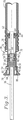
図5は、ストラップ26の両末端部に関し、改良されたハウジングアセンブリ88を使用する本発明の別の実施形態を示す。図1〜図4の実施形態に関して、各々のアセンブリ88は、ストラップ26の末端部フェルール76により固定される筒状のハウジング90を含む。ハウジング90は前端92と、対向する後端94とを有する。前端92は外側にねじ切られており、環状キャップ96が取り付けられる。
【0028】
前端92は、垂直の逃し通路100に通じている環状の逃し通路98を与えるよう配置される。環状の金属ブッシング102は、隣接する通路98に保持され、環状で、かつコップ状のシール受け104に隣接している。ブッシング102の後側の面と通路98との間には狭い隙間が与えられている。環状の弾性シール106はシール受け104内に置かれている。通路100はキャップ96とハウジング90の前端109との間の空隙または区域である108へと通じている。Oリング110は周囲にある通路98に関連して、末端部109の反対側に位置する。図示するように、環状ブッシング112はOリング110および末端部109とかみ合っている。ばね114はキャップ96とブッシング112との間の区域に位置している。ブッシング112に対するばね114のかみ合い力は、Oリング110を圧縮してシールを形成する作用をし、通常通路110を通じてのガスの漏洩を防ぐ。区域108と連絡しているキャップ96の壁面を通して酸素逃し用の開口部が設けられている(図示されていない)。
【0029】
ハウジング90の後端には、先に記述したシール62と類似のシール116が装着されており、シール116は図示するように、マウント36とかみ合っている環状のシーリング用弾性インナーリング118を保持する。ブッシングユニット120は要素36に固定され、環状の弾性ニアシール(near seal)122を保持する。シール122は、マウント36上に与えられた緩和区域124の前方ショルダーとかみ合いによって保持されている。開口部126は区域124でマウント36の壁面を貫通して設けられる。空洞部126はそれにより、シール122とハウジング90の前端92との間に形成される。
【0030】
図5の実施形態の使用は、先に示した第一の実施形態と全く同様に初期段階が進行する。すなわち、使用者はマスク本体をつかみ、ボタン25を押すことで加圧された酸素をマウント36を通じて流れさせ、ストラップ要素26を膨張させる。同時にそのような加圧酸素は開口部126を通じて流れ、空隙128を加圧する。これによりハウジング90およびストラップ要素の末端部38は、図5に示すように、空洞部128内の圧力がブッシング112およびOリング110に対するばね114のかみ合い力により予め設定された最大設定値を超えるまで左方向に移動する。この最大圧力を超過すると、酸素は通路100を通じて、続いてキャップの逃し開口部を通じて大気中に逃げ始める。これによりマウント36に対するハウジング90および末端部38のさらなる移動が防止される。ストラップ要素26の収縮時、空洞部128は加圧状態を維持している。
【0031】
図5に示した呼吸装置の使用時、空洞部128は加圧状態を維持し、マスクに関し快適な位置が保たれている。アセンブリ88に関するばねのかみ合い力を一度設定した後、図5の実施形態はさらに調整可能ではないことが好ましい。
【0032】
上記の実施形態のいずれもが、ストラップ要素26が完全に収縮した状態にある場合、マスクの装着面と使用者の顔面との間の圧迫力が無期限に快適な状態であることが好ましい。そのため、ストラップ26からの漏洩は装着感調節を維持する上での要因ではない。
【0033】
使用者が呼吸装置10の取り外しを望んだ場合、ボタン25を再度押し込むと、ストラップ要素が完全に膨張し、装置10を容易に取り外すことができる。この時点でストラップ要素26は再度収縮され、収納の準備ができた状態となる。
【図面の簡単な説明】
【図1】 本発明による好ましい呼吸装置の透視図である。
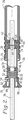
【図2】 マウント構造物を通常位置に示した膨張式ハーネスストラップの末端部の製造および図1に示す呼吸装置のマスクへの取り付けを例示した拡大断面図である。
【図3】 図2と同様であるが、マウント構造物の位置を最大伸長位置で示した図である。
【図4】 図2と同様であるが、マスクの装着面に関連して調節された膨張式ハーネスストラップの末端部の調節機構を示す図である。
【図5】 本発明の別の実施の形態を示した図であり、膨張式ハーネスストラップの製造および取り付けを例示している。[0001]
(Field of Invention)
The present invention broadly relates to respiratory devices of the type commonly used by civilian or private aircraft crews during emergencies. More specifically, when the present invention is worn, the first expansion and expansion make it easy to wear, and after the wear, the mask shrinks so that the mask is brought into close contact with the user's head. For a breathing apparatus having a full face or partial face mask with a possible inflatable strap coupled to the mask, the breathing apparatus of the present invention is adjusted to reduce the engagement force caused by the mask compressing the face By being able to do so, it includes a wearing feeling adjustment device for wearing the device for a long time without discomfort.
[0002]
(Description of prior art)
U.S. Pat. No. 3,599,636 discloses an inflatable head harness for a breathing apparatus, the harness being elongated and having an internal conduit connected to a valve for supplying pressurized air. Consisting of a mask attached to a simple harness or strap. When the valve is opened, the air supplied to the conduit in the strap stretches the strap, resulting in a defined shape. Accordingly, the user can hold the mask with one hand and guide the expanded strap to the back of the head. This is a particularly useful feature for emergency aircraft crew who can use only one hand.
[0003]
In the respiratory apparatus harness disclosed in US Pat. No. 3,599,636, once it is worn over the head, the strap contracts to shorten the length. Thereafter, the contracted strap causes the mask to be in close contact with the nose and mouth of the wearer's face due to its inherent elasticity, thereby preventing the suction gas from leaking from the periphery.
[0004]
Typically, when an aircraft flies more than 40,000 feet above sea level, aircraft crew masks are placed under pressure to force air into the lungs. Therefore, when flying at such an altitude, in order to overcome the pressure of oxygen trying to pull the mask away from the face and prevent leakage of oxygen from the mask edge seal, the strap is compared to the direction in which the mask is pressed against the face A large biasing force needs to be generated.
[0005]
However, in aircraft less than 40,000 feet above sea level, it is not necessary to place the space inside the mask in a pressurized breathing situation, and the regulator operates so that an oxygen-enriched air mixture is supplied only by the user's breathing demands. To do.
[0006]
In general, the substantial majority of flight time is less than 40,000 feet above sea level. However, there are many situations where it is mandatory to always wear a breathing mask, such as when there is only one crew member. Thus, in low altitude situations where a pressurized breathing situation is not required and in situations where the breathing apparatus is always required to be worn, the strap typically has a significant biasing force and the harness strap causes considerable discomfort.
[0007]
U.S. Pat. No. 5,036,846 discloses an inflatable harness-type occupant oxygen mask having a pneumatic feeling adjustment function. The means for adjusting the degree of expansion can adjust and maintain the pressure in the inflatable strap between the high pressure position where the strap is extended and the low pressure position where the strap is contracted. Similarly, US Pat. Nos. 5,623,923 and 5,503,147 allow the strap to be selectively inflated or deflated during use so that the user can have a comfortable fit. An apparatus for adjusting the wearing feeling of an inflatable strap is disclosed.
[0008]
The problems of these prior art wearing feeling adjustment devices stem from their adjustment mechanisms. That is, these adjustment methods depend on adjusting the pressure state in the strap, but if a large-scale leak occurs in the strap parts, there is a possibility that the wearing feeling adjustment function may become inoperable. Have.
[0009]
Accordingly, there is a need for an improved fit control device that forms part of an inflatable breathing device that can adjust the fit without the strap partially expanding or contracting when the breathing device is worn. ing. Preferably, such an improved fit feeling adjustment device should provide the desired fit feel adjustment even in situations where the strap is fully retracted and is substantially under atmospheric pressure.
[0010]
(Disclosure of the Invention)
The present invention solves the problems outlined above and provides an improved fit control device for an inflatable harness breathing device. Broadly speaking, the breathing apparatus of the present invention includes a mask that provides a wearing surface for intimate contact with the user's face, and has means for supplying pressurized gas for breathing into the mask. The mask is further attached with an extensible and selectively expandable and contractible strap having a pair of end portions that are functionally coupled to the mask. The strap has an enlarged shape so that it can be easily worn on the user's head when inflated, and when retracted, the user's head is tightened so that the mask is brought into close contact with the user's face. The wearing feeling adjusting device reduces the pressing force of the mask on the user's face. This wearing feeling adjusting device is composed of a mask mounting material that functionally holds at least one of the straps and can move while maintaining a connection between the end of the strap and the wearing surface of the mask. Furthermore, it has a stopper which fixes a terminal part to a mount member in the selected site | part corresponding to the mounting surface of a mask. As shown, in a preferred form, movement with such a connection occurs when the strap is fully contracted.
[0011]
Preferably, the straps are attached so as to be held in an adjustable manner on the corresponding mounting members at both ends. Thereby, the components on one side or both sides of the strap can be adjusted.
[0012]
The mounting members are secured in a convenient orientation to be oriented coaxially inside a corresponding housing assembly secured to the distal end of the inflatable strap with an elongated tubular body. In this configuration, the end of the strap can be adjusted coaxially along the length of the mount to change the distance between the end and the mounting surface of the mask. In addition, the fixed tubular mount is fitted with a mask regulator so that it acts as a means for expansion and contraction of the strap. Each housing assembly includes an elongated cylindrical housing secured to a corresponding strap end. A pair of opposed seals (front seal, rear seal) are installed in the housing in an annular shape, and the cavity is partitioned by these. One of the seals is movable in the housing, and the other one is fixed to the cylindrical mount. An opening is provided in the wall surface between the front seal and the rear seal. During the expansion of the strap, the housing and the strap end move along the longitudinal direction of the tubular housing to the normal or initial position, and the cavity is pressurized with the strap. As the strap contracts substantially to ambient internal pressure, the cavity is also evacuated. Moreover, the distal end attached to the housing assembly and strap can be manually adjusted along the length of the cylindrical mount. This effectively increases the internal dimensions of the strap and reduces the masking pressure on the user's face.
[0013]
In another aspect, a similar wearing feel adjustment device is provided that operates such that the wearing surface of the mask is located at a preset intermediate position relative to the distal end of the strap. In this adjustment mechanism, a relief valve (release hole) that is normally closed by a spring-loaded seal is attached to the housing. Upon expansion of the strap, the cavity of the housing is pressurized until its internal pressure overcomes the spring-loaded seal and pressurized gas begins to be released from the cavity into the atmosphere. When the strap is contracted, the cavity of the housing maintains a pressurized state.
[0014]
(Preferred embodiment)
With reference to the drawings, in particular FIG. 1, a
[0015]
More specifically, the
[0016]
The
[0017]
As shown in the drawing, the wearing
[0018]
A fixed
[0019]
Specifically with respect to mount 36, it has an opening on its side and an adjacent relief area 68 formed on its outer side. The
[0020]
The ends 28 and 30 of the
[0021]
An
[0022]
The use of the configuration of FIGS. 1-4 proceeds as follows, assuming that the mask is stored in a ready position, usually a storage box next to the crew seat. When retracted, both ends 28 and 30 of the
[0023]
After wearing the mask with the strap inflated, the user releases the button. As a result, oxygen in the strap element flows back through the
[0024]
In the initial contracted state, it is preferred that the strap element is very tightly attached to the user's head and is uncomfortable. In order to obtain a more comfortable fit, the user may then optionally depress, as best shown in FIG. By doing so, the
[0025]
Of course, either one or both of the
[0026]
FIG. 3 shows the
[0027]
FIG. 5 illustrates another embodiment of the present invention using an
[0028]
The
[0029]
A
[0030]
The use of the embodiment of FIG. 5 proceeds in the initial stage exactly as in the first embodiment shown above. That is, the user grasps the mask body and presses the
[0031]
When the breathing apparatus shown in FIG. 5 is used, the
[0032]
In any of the above embodiments, when the
[0033]
If the user wishes to remove the
[Brief description of the drawings]
FIG. 1 is a perspective view of a preferred respiratory device according to the present invention.
2 is an enlarged cross-sectional view illustrating the manufacture of the distal end of the inflatable harness strap with the mounting structure in the normal position and the attachment of the respiratory apparatus shown in FIG. 1 to the mask.
FIG. 3 is a view similar to FIG. 2, but showing the position of the mount structure in the maximum extended position.
FIG. 4 is a view similar to FIG. 2, but showing the adjustment mechanism for the distal end of the inflatable harness strap adjusted relative to the mask mounting surface.
FIG. 5 is a diagram illustrating another embodiment of the present invention, illustrating the manufacture and attachment of an inflatable harness strap.
Claims (11)
前記呼吸装置を前記使用者の顔面に密着させるのに使用する装着面を与えるマスクと、
前記マスクに加圧された呼吸用ガスを供給するための手段と、
前記マスクと機能的に結合する一対の末端部を与える伸縮可能で、かつ選択的に膨張収縮可能なストラップ要素とからなり、
前記ストラップ要素が膨張すると使用者の頭部に容易に装着できるよう拡大された形状となり、
前記ストラップ要素が収縮すると初期位置(ストラップ要素が収縮した直後の、マスクの装着面に対する、ストラップ要素の一つの端末部の位置)に移動して使用者の頭部に締め付けるようになり、それによって前記マスクが使用者の顔面に密着するように引き寄せられる性質を有する呼吸装置であって、
前記呼吸装置の装着感調節装置が、マスクによる使用者の顔面への圧迫力を減少させるよう改善されており、
前記装着感調節装置が前記ストラップ要素末端部のうち少なくとも一つの末端部を保持し、かつ前記一つのストラップ要素末端部と前記マスクの装着面との間で結合を保ったまま移動することが可能なマスクのマウント材と、
前記一つのストラップ要素末端部を前記マウント材に固定する止め具と、
収縮して前記初期位置となり、前記マスクを前記使用者の顔面に密着するよう引き寄せる時に、前記止め具との固定を選択的に解除し、前記一つの要素末端部と前記マスクの装着面との相対位置を多数の位置のうちのいずれにも調節することができる調節装置とからなり、
前記止め具がストラップ要素末端部を前記マウント材上の多数の位置のいずれの位置にも固定可能な止め具であって、
前記マウント材がストラップ要素が膨張収縮サイクルを受ける際に、サイクル前の前記ストラップ要素末端部の位置に関係なく、前記ストラップ要素を前記初期位置に再び戻すことができる機構を含む呼吸装置。In a respiratory device that is worn on the user's head,
A mask that provides a wearing surface that is used to bring the respiratory device into close contact with the user's face;
Means for supplying pressurized respiratory gas to the mask;
A stretchable and selectively expandable / shrinkable strap element that provides a pair of end portions functionally coupled to the mask;
When the strap element expands, it becomes an enlarged shape so that it can be easily attached to the user's head,
When the strap element contracts, it moves to an initial position ( position of one end of the strap element with respect to the mask mounting surface immediately after the strap element contracts) and tightens to the user's head, thereby A respiratory apparatus having the property of being drawn so that the mask is in close contact with the user's face,
The device for adjusting the feeling of wearing the breathing apparatus has been improved to reduce the pressure applied to the user's face by the mask,
The attachment feeling adjusting device holds at least one end portion of the strap element end portions and can move while maintaining a connection between the one strap element end portion and the mounting surface of the mask. Mask mounting material,
A stop for securing the one strap element end to the mount;
When the mask is retracted to the initial position and the mask is pulled close to the user's face, the fixing with the stopper is selectively released, and the end of the one element and the mounting surface of the mask An adjustment device that can adjust the relative position to any of a number of positions,
The stopper is capable of fixing a strap element end to any of a number of positions on the mount;
A respirator comprising a mechanism that allows the mounting element to return the strap element back to the initial position when the strap element undergoes an expansion and contraction cycle, regardless of the position of the end of the strap element prior to cycling.
Applications Claiming Priority (3)
| Application Number | Priority Date | Filing Date | Title |
|---|---|---|---|
| US08/954,459 | 1997-10-20 | ||
| US08/954,459 US5941245A (en) | 1997-10-20 | 1997-10-20 | Crew oxygen mask with improved comfort control apparatus |
| PCT/US1998/019035 WO1999020349A1 (en) | 1997-10-20 | 1998-09-11 | Crew oxygen mask with improved comfort control apparatus |
Publications (3)
| Publication Number | Publication Date |
|---|---|
| JP2001520097A JP2001520097A (en) | 2001-10-30 |
| JP2001520097A5 JP2001520097A5 (en) | 2007-09-20 |
| JP4031907B2 true JP4031907B2 (en) | 2008-01-09 |
Family
ID=25495451
Family Applications (1)
| Application Number | Title | Priority Date | Filing Date |
|---|---|---|---|
| JP2000516736A Expired - Lifetime JP4031907B2 (en) | 1997-10-20 | 1998-09-11 | Crew Oxygen Mask with Improved Wearability Adjustment Device |
Country Status (8)
| Country | Link |
|---|---|
| US (1) | US5941245A (en) |
| EP (1) | EP1024861B1 (en) |
| JP (1) | JP4031907B2 (en) |
| AT (1) | ATE273732T1 (en) |
| AU (1) | AU730227B2 (en) |
| CA (1) | CA2315870C (en) |
| DE (1) | DE69825770T2 (en) |
| WO (1) | WO1999020349A1 (en) |
Families Citing this family (56)
| Publication number | Priority date | Publication date | Assignee | Title |
|---|---|---|---|---|
| US5664566A (en) * | 1994-09-30 | 1997-09-09 | Puritan-Bennett Corporation | Quick-donning full face oxygen mask with inflatable harness and soft foldable lens |
| US6732733B1 (en) | 1997-10-03 | 2004-05-11 | 3M Innovative Properties Company | Half-mask respirator with head harness assembly |
| US6062221A (en) | 1997-10-03 | 2000-05-16 | 3M Innovative Properties Company | Drop-down face mask assembly |
| US6318369B1 (en) * | 1998-03-05 | 2001-11-20 | Kenneth M. Gregory | Eye ear and respiration protection apparatus |
| FR2778575B1 (en) * | 1998-05-12 | 2000-07-28 | Intertechnique Sa | RESPIRATORY PROTECTION EQUIPMENT WITH FAST SETUP |
| FR2781381B1 (en) * | 1998-07-24 | 2000-09-29 | Intertechnique Sa | ON-DEMAND REGULATOR FOR RESPIRATORY SYSTEM |
| FR2806000B1 (en) * | 2000-03-10 | 2002-05-31 | Intertechnique Sa | QUICK-SETTING HEAD PROTECTION EQUIPMENT |
| FR2823123B1 (en) | 2001-04-06 | 2003-05-23 | Robert Schegerin | FAST SETUP PHYSIOLOGICAL PROTECTION EQUIPMENT |
| US10463828B2 (en) * | 2001-10-10 | 2019-11-05 | Fisher & Paykel Healthcare Limited | Breathing assistance apparatus |
| AU2003279034A1 (en) * | 2002-09-30 | 2004-04-23 | Be Intellectual Property, Inc. | Full face flexible oxygen mask for use with flight helmets |
| DE10333585A1 (en) * | 2003-07-24 | 2005-02-24 | Dräger Safety AG & Co. KGaA | Respiratory protection product with an electrical component |
| US8783257B2 (en) | 2004-02-23 | 2014-07-22 | Fisher & Paykel Healthcare Limited | Breathing assistance apparatus |
| WO2005094928A1 (en) | 2004-04-02 | 2005-10-13 | Fisher & Paykel Healthcare Limited | Breathing assistance apparatus |
| US9072852B2 (en) | 2004-04-02 | 2015-07-07 | Fisher & Paykel Healthcare Limited | Breathing assistance apparatus |
| US7827987B2 (en) | 2005-06-17 | 2010-11-09 | Nellcor Puritan Bennett Llc | Ball joint for providing flexibility to a gas delivery pathway |
| US7900630B2 (en) | 2005-06-17 | 2011-03-08 | Nellcor Puritan Bennett Llc | Gas delivery mask with flexible bellows |
| US7490608B2 (en) * | 2005-06-17 | 2009-02-17 | Nellcorr Puritan Bennett Llc | System and method for adjusting a gas delivery mask |
| US7849855B2 (en) | 2005-06-17 | 2010-12-14 | Nellcor Puritan Bennett Llc | Gas exhaust system for a gas delivery mask |
| US8245711B2 (en) | 2005-08-15 | 2012-08-21 | Ric Investments, Llc | Patient interface with adjustable cushion |
| GB0606241D0 (en) * | 2006-03-29 | 2006-05-10 | Concept 2 Manufacture Design L | An improved harness for breathing apparatus |
| CA2890556C (en) | 2006-07-14 | 2018-05-01 | Fisher & Paykel Healthcare Limited | Breathing assistance apparatus |
| DE602007005377D1 (en) * | 2006-08-10 | 2010-04-29 | Intertechnique Sa | ATEM MASK WITH AUTONOMIC INFLATABLE BELT |
| US8109271B2 (en) * | 2006-09-07 | 2012-02-07 | Nellcor Puritan Bennett Llc | Method and apparatus for securing a patient interface to a patient's face |
| CA2602005A1 (en) | 2006-09-18 | 2008-03-18 | Invacare Corporation | Breathing mask |
| EP2114535B1 (en) * | 2007-02-05 | 2017-01-11 | BE Intellectual Property, Inc. | Inflatable harness crew mask |
| US10258757B2 (en) | 2008-05-12 | 2019-04-16 | Fisher & Paykel Healthcare Limited | Patient interface and aspects thereof |
| US10792451B2 (en) | 2008-05-12 | 2020-10-06 | Fisher & Paykel Healthcare Limited | Patient interface and aspects thereof |
| US11660413B2 (en) | 2008-07-18 | 2023-05-30 | Fisher & Paykel Healthcare Limited | Breathing assistance apparatus |
| WO2010041966A1 (en) | 2008-10-10 | 2010-04-15 | Fisher & Paykel Healthcare Limited | Nasal pillows for a patient interface |
| US10137271B2 (en) | 2009-11-18 | 2018-11-27 | Fisher & Paykel Healthcare Limited | Nasal interface |
| GB2534305A (en) | 2009-12-23 | 2016-07-20 | Fisher & Paykel Healthcare Ltd | Patient interface and headgear |
| US10118056B2 (en) * | 2010-01-22 | 2018-11-06 | Zodiac Aerotechnics | Breathing assembly for aircraft |
| US9561338B2 (en) | 2010-10-08 | 2017-02-07 | Fisher & Paykel Healthcare Limited | Breathing assistance apparatus |
| US10603456B2 (en) | 2011-04-15 | 2020-03-31 | Fisher & Paykel Healthcare Limited | Interface comprising a nasal sealing portion |
| DE112012007300B4 (en) | 2011-04-15 | 2024-04-25 | Fisher & Paykel Healthcare Ltd. | Interface with a movable nose bridge |
| CN104023798B (en) | 2011-10-31 | 2018-02-06 | 佐迪埃克航空技术公司 | Store the method for breathing mask and the breathing equipment including breathing mask and storage element |
| CN107626023B (en) | 2012-08-08 | 2021-03-02 | 费雪派克医疗保健有限公司 | Interface assembly for use in providing respiratory therapy |
| EP2892596B1 (en) | 2012-09-04 | 2023-07-26 | Fisher&Paykel Healthcare Limited | Valsalva mask |
| USD751687S1 (en) * | 2013-09-26 | 2016-03-15 | The Periodic Breathing Foundation, Llc | Tubing set |
| USD751688S1 (en) * | 2013-09-26 | 2016-03-15 | The Periodic Breathing Foundation, Llc | Tubing set interface |
| US20160346496A1 (en) * | 2014-07-16 | 2016-12-01 | Human Design Medical, Llc | Facial interface and headgear system for use with ventilation and positive air pressure systems |
| GB2587307B (en) | 2014-08-25 | 2021-10-27 | Fisher & Paykel Healthcare Ltd | Respiratory mask and related portions, components or sub-assemblies |
| TW202332392A (en) | 2014-09-16 | 2023-08-16 | 紐西蘭商費雪 & 佩凱爾關心健康有限公司 | Intramold headgear |
| US10646680B2 (en) * | 2014-09-19 | 2020-05-12 | Fisher & Paykel Healthcare Limited | Headgear assemblies and interface assemblies with headgear |
| CN115212416A (en) | 2016-03-16 | 2022-10-21 | 费雪派克医疗保健有限公司 | Bandage subassembly |
| SG11201807697QA (en) | 2016-03-16 | 2018-10-30 | Fisher & Paykel Healthcare Ltd | Intra-mould substrate |
| AU2017234346B2 (en) | 2016-03-16 | 2022-06-30 | Fisher & Paykel Healthcare Limited | Directional lock for interface headgear arrangement |
| USD882066S1 (en) | 2016-05-13 | 2020-04-21 | Fisher & Paykel Healthcare Limited | Frame for a breathing mask |
| USD823454S1 (en) | 2017-02-23 | 2018-07-17 | Fisher & Paykel Healthcare Limited | Cushion assembly for breathing mask assembly |
| USD823455S1 (en) | 2017-02-23 | 2018-07-17 | Fisher & Paykel Healthcare Limited | Cushion assembly for breathing mask assembly |
| USD824020S1 (en) | 2017-02-23 | 2018-07-24 | Fisher & Paykel Healthcare Limited | Cushion assembly for breathing mask assembly |
| WO2019008446A1 (en) * | 2017-07-05 | 2019-01-10 | Zodiac Aerotechnics | Quick donning comfortable respiratory mask system for aircraft pilot |
| AU2019235660A1 (en) * | 2018-03-16 | 2020-09-24 | Fisher & Paykel Healthcare Limited | Headgear with lock disengagement mechanism |
| CN111729169A (en) * | 2020-06-19 | 2020-10-02 | 界首市华盛塑料机械有限公司 | Breathing mask self-wearing mechanism and monitoring equipment based on same |
| CN114504745A (en) * | 2022-03-08 | 2022-05-17 | 吴江兵 | Breathing mask used under water |
| JP2024051720A (en) * | 2022-09-30 | 2024-04-11 | 株式会社重松製作所 | Respiratory system |
Family Cites Families (21)
| Publication number | Priority date | Publication date | Assignee | Title |
|---|---|---|---|---|
| US2287939A (en) * | 1939-09-21 | 1942-06-30 | Gen Tire & Rubber Co | Respirator |
| US2449548A (en) * | 1946-01-03 | 1948-09-21 | Henry L Burns | Automatic control system for high altitude pressure suits |
| GB861574A (en) * | 1956-05-08 | 1961-02-22 | Airmed Ltd | Improvements in or relating to appliances for attaching articles such as respiratorymasks to a user's head |
| US3040741A (en) * | 1958-12-15 | 1962-06-26 | Puritan Compressed Gas Corp | Quick donning harness for oxygen masks |
| US3056402A (en) * | 1959-05-26 | 1962-10-02 | Airmed Ltd | Respiratory masks |
| US3347566A (en) * | 1964-10-26 | 1967-10-17 | Scott Aviation Corp | Breakaway coupling assembly |
| SE332353B (en) * | 1969-09-18 | 1971-02-01 | I Hellqvist | |
| US3599636A (en) * | 1969-12-12 | 1971-08-17 | Intertechnique Sa | Inflatable head harness for respirator devices |
| US3850168A (en) * | 1971-09-21 | 1974-11-26 | Puritan Bennett Corp | Oxygen mask apparatus |
| US3792702A (en) * | 1972-04-10 | 1974-02-19 | Ulmer & Co Soc | Harness for rapidly placing in position a device such as a respirator mask |
| DE3201365A1 (en) * | 1981-10-06 | 1983-04-14 | Beckmann KG, 7410 Reutlingen | Device for preventing axial movement of a guided round-profiled body, especially of a tap tube in a beer keg |
| US4437462A (en) * | 1981-11-19 | 1984-03-20 | Figgie International Inc. | Pneumatic head harness |
| US4664108A (en) * | 1984-05-25 | 1987-05-12 | Figgie International Inc. | Oxygen supply system and device therefor |
| FR2614208B1 (en) * | 1987-04-22 | 1989-09-08 | Intertechnique Sa | BREATHING MASK HARNESS AND MASK COMPRISING APPLICATION. |
| US5036846A (en) * | 1988-02-26 | 1991-08-06 | Puritan-Bennett Corporation | Crew oxygen mask with pneumatic comfort adjustment |
| US4915106A (en) * | 1988-02-26 | 1990-04-10 | Puritan-Bennett Corporation | Crew oxygen mask with pneumatic comfort adjustment |
| US5307793A (en) | 1992-06-29 | 1994-05-03 | Puritan-Bennett Corporation | Microphone signal attenuating apparatus for oxygen masks |
| DE4310818A1 (en) * | 1993-04-02 | 1994-10-06 | Walther Carl Kurt Gmbh | Plug-in coupling |
| FR2706311B1 (en) * | 1993-06-09 | 1995-09-22 | Intertechnique Sa | Respiratory protection equipment. |
| US5623923A (en) * | 1993-06-09 | 1997-04-29 | Intertechnique | Respiratory equipment with comfort adjustment |
| US5664566A (en) * | 1994-09-30 | 1997-09-09 | Puritan-Bennett Corporation | Quick-donning full face oxygen mask with inflatable harness and soft foldable lens |
-
1997
- 1997-10-20 US US08/954,459 patent/US5941245A/en not_active Expired - Lifetime
-
1998
- 1998-09-11 CA CA002315870A patent/CA2315870C/en not_active Expired - Lifetime
- 1998-09-11 DE DE69825770T patent/DE69825770T2/en not_active Expired - Lifetime
- 1998-09-11 AU AU92305/98A patent/AU730227B2/en not_active Expired
- 1998-09-11 WO PCT/US1998/019035 patent/WO1999020349A1/en active IP Right Grant
- 1998-09-11 JP JP2000516736A patent/JP4031907B2/en not_active Expired - Lifetime
- 1998-09-11 EP EP98944861A patent/EP1024861B1/en not_active Expired - Lifetime
- 1998-09-11 AT AT98944861T patent/ATE273732T1/en not_active IP Right Cessation
Also Published As
| Publication number | Publication date |
|---|---|
| ATE273732T1 (en) | 2004-09-15 |
| DE69825770D1 (en) | 2004-09-23 |
| CA2315870C (en) | 2007-06-26 |
| AU730227B2 (en) | 2001-03-01 |
| JP2001520097A (en) | 2001-10-30 |
| US5941245A (en) | 1999-08-24 |
| EP1024861A1 (en) | 2000-08-09 |
| DE69825770T2 (en) | 2005-08-25 |
| EP1024861B1 (en) | 2004-08-18 |
| CA2315870A1 (en) | 1999-04-29 |
| EP1024861A4 (en) | 2001-09-19 |
| WO1999020349A1 (en) | 1999-04-29 |
| AU9230598A (en) | 1999-05-10 |
Similar Documents
| Publication | Publication Date | Title |
|---|---|---|
| JP4031907B2 (en) | Crew Oxygen Mask with Improved Wearability Adjustment Device | |
| JP2890359B2 (en) | Occupant oxygen mask with pneumatic comfort control | |
| US6470887B1 (en) | Protective breathing equipment with fast positioning | |
| US5036846A (en) | Crew oxygen mask with pneumatic comfort adjustment | |
| US5623923A (en) | Respiratory equipment with comfort adjustment | |
| US5503147A (en) | Respiratory equipment with comfort adjustment | |
| US3599636A (en) | Inflatable head harness for respirator devices | |
| US6039045A (en) | Head harness for respiratory mask | |
| EP0541569A1 (en) | Improved breathing equipment for aircrew. | |
| EP1389482A1 (en) | Oxygen Mask | |
| US5771886A (en) | Inflatable head harness with hearing device placement | |
| CA2440431C (en) | High g oxygen mask for aircrew | |
| US20180361179A1 (en) | Respiratory equipment for aircraft, with inflatable mask and harness, and its storage space | |
| US3044464A (en) | Lower face, high pressure mask | |
| JP4869400B2 (en) | Respirator with a stand-alone inflatable harness | |
| ES369354A1 (en) | Exhalation device for breathing mask | |
| AU2004201337A1 (en) | Oxygen Mask with Flexible Face Seal | |
| US2778599A (en) | Parachute inflating means | |
| US3284805A (en) | Combined cabin uniform and mechanical partial pressure suit complete with helmet | |
| US3035594A (en) | Combination inhalator-exhalator valve with hose pull protection | |
| RU2177812C1 (en) | Breathing apparatus | |
| GB2408459A (en) | High G breathing mask with enhanced seal |
Legal Events
| Date | Code | Title | Description |
|---|---|---|---|
| A621 | Written request for application examination |
Free format text: JAPANESE INTERMEDIATE CODE: A621 Effective date: 20050909 |
|
| A977 | Report on retrieval |
Free format text: JAPANESE INTERMEDIATE CODE: A971007 Effective date: 20070510 |
|
| A131 | Notification of reasons for refusal |
Free format text: JAPANESE INTERMEDIATE CODE: A131 Effective date: 20070515 |
|
| A521 | Request for written amendment filed |
Free format text: JAPANESE INTERMEDIATE CODE: A523 Effective date: 20070628 |
|
| A524 | Written submission of copy of amendment under article 19 pct |
Free format text: JAPANESE INTERMEDIATE CODE: A524 Effective date: 20070628 |
|
| TRDD | Decision of grant or rejection written | ||
| A01 | Written decision to grant a patent or to grant a registration (utility model) |
Free format text: JAPANESE INTERMEDIATE CODE: A01 Effective date: 20070925 |
|
| A61 | First payment of annual fees (during grant procedure) |
Free format text: JAPANESE INTERMEDIATE CODE: A61 Effective date: 20071022 |
|
| R150 | Certificate of patent or registration of utility model |
Free format text: JAPANESE INTERMEDIATE CODE: R150 |
|
| FPAY | Renewal fee payment (event date is renewal date of database) |
Free format text: PAYMENT UNTIL: 20101026 Year of fee payment: 3 |
|
| FPAY | Renewal fee payment (event date is renewal date of database) |
Free format text: PAYMENT UNTIL: 20111026 Year of fee payment: 4 |
|
| FPAY | Renewal fee payment (event date is renewal date of database) |
Free format text: PAYMENT UNTIL: 20121026 Year of fee payment: 5 |
|
| FPAY | Renewal fee payment (event date is renewal date of database) |
Free format text: PAYMENT UNTIL: 20131026 Year of fee payment: 6 |
|
| R250 | Receipt of annual fees |
Free format text: JAPANESE INTERMEDIATE CODE: R250 |
|
| R250 | Receipt of annual fees |
Free format text: JAPANESE INTERMEDIATE CODE: R250 |
|
| R250 | Receipt of annual fees |
Free format text: JAPANESE INTERMEDIATE CODE: R250 |
|
| R250 | Receipt of annual fees |
Free format text: JAPANESE INTERMEDIATE CODE: R250 |
|
| R250 | Receipt of annual fees |
Free format text: JAPANESE INTERMEDIATE CODE: R250 |
|
| EXPY | Cancellation because of completion of term |