JP4030552B2 - Soft ice cream food bowl - Google Patents
Soft ice cream food bowl Download PDFInfo
- Publication number
- JP4030552B2 JP4030552B2 JP2005121772A JP2005121772A JP4030552B2 JP 4030552 B2 JP4030552 B2 JP 4030552B2 JP 2005121772 A JP2005121772 A JP 2005121772A JP 2005121772 A JP2005121772 A JP 2005121772A JP 4030552 B2 JP4030552 B2 JP 4030552B2
- Authority
- JP
- Japan
- Prior art keywords
- lever
- container
- cam
- moving
- food
- Prior art date
- Legal status (The legal status is an assumption and is not a legal conclusion. Google has not performed a legal analysis and makes no representation as to the accuracy of the status listed.)
- Expired - Fee Related
Links
Images


Landscapes
- Confectionery (AREA)
Description
この発明は、コンビニ等の店舗に設置され、ソフトクリーム状食品(例えばソフトクリーム、ホイップドクリーム、ムース、ババロア等の冷菓)を可塑性状態保持下で小分け用押出し容器からコーン等の喫食用容器へ盛り付けるためのソフトクリーム状食品の盛り付け器、さらに詳しくは自動、手動の両方の盛り付けを可能とした小型の盛り付け器に関するものである。 This invention is installed in a store such as a convenience store, and soft ice cream food (for example, ice cream such as soft cream, whipped cream, mousse, and bavaroa) is kept in a plastic state from an extruding container for dispensing into a container such as corn. More specifically, the present invention relates to a small-sized plate that can be used for both automatic and manual packing.
従来、この種の盛り付け器の一例としては、この出願人から先に提案したものが知られている(例えば、特許文献1参照)。これは載置台に載置された容器を押圧して内部に収納したソフトクリーム状食品をその排出口から下方にあるコーンに排出する際にねじれ巻きにされた状態に盛り付けるもので、特許文献1の第4頁及び図1,2,4に示すように、盛り付けに際しては、容器(10)をセットした容器ホルダ(9)を押出し位置イに位置するようにセットした後、図示しないスイッチをオンしてモータ(61)を正転駆動すると、駆動軸(56)が回転し、これとともにカム(57)の回転によってハンマーカムレバー(50)が下方に引かれ、ハンマーレバーが下方に揺動され、押圧ヘッド(42)の押圧面(42a)が容器(10)の上面に当ってこれを押圧し、内部に収納したアイスクリームを下部排出口から排出させる。一方、駆動軸(56)の回転により昇降カム(71)も回転され、この昇降カムの回転によりその外周面と衝合したカムローラ(70)が次第に押し下げられ、これとともに揺動レバー(67)が下方へ揺動し、凹溝(74)でガイドピン(76)と係合する上下動体(75)を下動させる。 Conventionally, as an example of this type of applicator, one previously proposed by the applicant is known (see, for example, Patent Document 1). This is to serve a twisted roll when the soft cream-like food housed in the container by pressing the container placed on the mounting table is discharged from the discharge port to the cone located below. As shown in Fig. 4 and Figs. 1, 2, and 4, when placing the container holder (9) in which the container (10) is set so that it is positioned at the pushing position (a), a switch (not shown) is turned on. Then, when the motor (61) is driven to rotate forward, the drive shaft (56) rotates, and at the same time, the rotation of the cam (57) pulls the hammer cam lever (50) downward, and the hammer lever swings downward, The pressing surface (42a) of the pressing head (42) hits and presses the upper surface of the container (10), and the ice cream stored inside is discharged from the lower discharge port. On the other hand, the raising / lowering cam (71) is also rotated by the rotation of the drive shaft (56), and the rotation of the raising / lowering cam gradually pushes down the cam roller (70) that abuts on the outer peripheral surface, and the swing lever (67) is also moved with this The vertical moving body (75) that swings downward and engages with the guide pin (76) is moved downward by the concave groove (74).
上下動体(75)が下動すると、ブラケット(77)の回転軸(80)に取り付けられたガイドピン(86)がカム溝(88)に沿ってその上端から下端に向けて摺動し、このカム溝(88)を摺動する間に回転受皿(82)が所定角度回転させられる。そして図4のようにカム(57)の凹部(65)にカムローラ(53)が落ち込みしばらくすると、カムスイッチがオンして、モータ(61)の駆動が停止し、上下動体(75)は最下位にもたらされる。前記の上下動体(75)の下動と該上下動体(75)に取り付けられた回転受皿(82)の回転により、取付台(84)上のコーン(83)には容器(10)の排出口から排出されたアイスクリームが図4のように排出口の形状に対応した形状の、ねじれ巻きにされた状態に盛り付けられる。 When the vertically moving body (75) moves downward, the guide pin (86) attached to the rotating shaft (80) of the bracket (77) slides along the cam groove (88) from its upper end to its lower end. While sliding the cam groove (88), the rotating tray (82) is rotated by a predetermined angle. Then, as shown in FIG. 4, the cam roller (53) falls into the recess (65) of the cam (57) and after a while, the cam switch is turned on, the drive of the motor (61) is stopped, and the vertical moving body (75) is at the lowest position. Brought to you. By the downward movement of the vertical moving body (75) and the rotation of the rotating tray (82) attached to the vertical moving body (75), the cone (83) on the mounting base (84) has a discharge port for the container (10). As shown in FIG. 4, the ice cream discharged from the container is arranged in a twisted state having a shape corresponding to the shape of the discharge port.
ところで、特許文献1の盛り付け器では、揺動レバー(67)の前端部に先端開口の凹溝(74)が形成され、該凹溝に上下動体(75)の上端側面に設けたガイドピン(76)が係合されており、ガイドピン(76)が凹溝(74)に常に係合した状態となるため、容器(10)への押圧作動と回転受皿(82)の回転の連動が必須となった自動盛り付けが前提である。したがって、例えばデザートにアイスクリームを好みの形状に盛り付けるようなときには手動盛り付けの要請があるが、それが不可能であるという問題があった。尚、業務用の大型盛り付け機では手動盛り付けが可能なものがないことはないが、特許文献1の盛り付け器のようなコンビニ等に設置される小型の盛り付け器ではなく、その実現要請が強い。 By the way, in the applicator of Patent Document 1, a groove (74) having a tip opening is formed at the front end of the swing lever (67), and a guide pin (on the upper side surface of the vertical moving body (75)) is provided in the groove. 76) is engaged, and the guide pin (76) is always engaged with the concave groove (74), so the pressing operation on the container (10) and the rotation of the rotating tray (82) are essential. It is premised on automatic arrangement. Therefore, for example, when dessert ice cream is arranged in a desired shape, there is a request for manual arrangement, but there is a problem that this is impossible. In addition, although there is no thing that can be manually placed in a large-scale placement machine for business use, it is not a small placement device installed in a convenience store or the like such as the placement device of Patent Document 1, and there is a strong demand for its realization.
そこでこの発明は、前記従来のものの問題点を解決し、小型の盛り付け器でも手動盛り付けができ、自動及び手動の両方の盛り付けが可能なソフトクリーム状食品の盛り付け器を提供することを目的とする。 SUMMARY OF THE INVENTION Accordingly, an object of the present invention is to solve the above-mentioned problems of the conventional ones and to provide a soft cream food food applicator that can be manually provided with a small applicator and can be provided both automatically and manually. .
前記課題を解決するために、請求項1に記載の発明は、容器載置台と、該載置台に対して上下動可能に配置された押圧部材と、該押圧部材を上下動させる第1の作動機構と、該作動機構と連動して上下動し、かつ食品受部を載置台の下方位置からさらに下方の所定位置へ移動する間に回転させる第2の作動機構と、第1の作動機構を作動するための操作スイッチとを具え、この操作スイッチによって第1の作動機構を作動することにより押圧部材を下動させ、載置台に載置された容器を押圧して内部に収納したソフトクリーム状食品をその排出口から下方の食品受部に向けて排出させるソフトクリーム状食品の盛り付け器において、第1の作動機構は、上下に揺動する揺動レバーを有し、第2の作動機構は、上下に移動する上下動体を有し、前記揺動レバーの前端部に設けた先端開口の凹溝と前記上下動体の上端側面に設けたガイドピンが係脱可能になっており、また前記揺動レバーは、固定レバー部と、該レバー部の長手方向に移動可能となった移動レバー部とを有し、固定レバー部の前端部に凹溝を形成する切欠半部が形成され、該切欠半部と対応する移動レバー部の前端部に凹溝を形成する切欠半部が形成されており、前記凹溝とガイドピンを自動盛付時に係合し、手動盛付時に離脱するように係脱させる作動部材が設けられ、該作動部材を作動するための操作スイッチが設けられていることを特徴とする。 In order to solve the above-mentioned problem, the invention described in claim 1 includes a container mounting table, a pressing member arranged to be movable up and down with respect to the mounting table, and a first operation for moving the pressing member up and down. A mechanism, a second operating mechanism that moves up and down in conjunction with the operating mechanism, and that rotates the food receiving portion while moving the food receiving section from a lower position of the mounting table to a predetermined position further below, and a first operating mechanism. A soft cream that has an operation switch for actuating, operates the first actuating mechanism by this operation switch, moves down the pressing member, presses the container placed on the placing table, and stores it inside In the serving device for soft cream food that discharges food from its outlet toward the food receiving portion below, the first operating mechanism has a swing lever that swings up and down, and the second operating mechanism is Has a vertically moving body that moves up and down, Guide pins provided on the upper end side of the distal opening of the groove formed in the front end portion of KiYurado lever the vertical movement body has enabled disengaged and said rocking lever includes a fixed lever portion, the lever A movable lever part that is movable in the longitudinal direction of the part, and a notch half part that forms a concave groove is formed in the front end part of the fixed lever part, and the front end part of the movable lever part corresponding to the notch half part A notch half is formed in the groove, and an operating member is provided to engage and disengage the concave groove and the guide pin so as to engage and disengage so as to disengage during manual assembling. An operation switch for actuating is provided.
請求項2に記載の発明は、請求項1において、移動レバー部の前端部は、固定レバー部の前端部と凹溝を形成する第1の位置と、該位置から固定レバー部の前端部方向の離れた第2の位置との間に屈曲可能になっており、かつ第1の位置に位置したときその状態を保持する付勢部材が設けられていることを特徴とする。 According to a second aspect of the present invention, in the first aspect, the front end portion of the moving lever portion has a first position that forms a groove with the front end portion of the fixed lever portion, and the front end portion direction of the fixed lever portion from the position. A biasing member is provided that is bendable between the second position and the second position, and that holds the state when the second position is located at the first position .
この発明は、前記のようであって、第1の作動機構は、上下に揺動する揺動レバーを有し、第2の作動機構は、上下に移動する上下動体を有し、前記揺動レバーの前端部に設けた先端開口の凹溝と前記上下動体の上端側面に設けたガイドピンが係脱可能になっており、また前記揺動レバーは、固定レバー部と、該レバー部の長手方向に移動可能となった移動レバー部とを有し、固定レバー部の前端部に凹溝を形成する切欠半部が形成され、該切欠半部と対応する移動レバー部の前端部に凹溝を形成する切欠半部が形成されており、前記凹溝とガイドピンを自動盛付時に係合し、手動盛付時に離脱するように係脱させる作動部材が設けられ、該作動部材を作動するための操作スイッチが設けられているので、従来は自動盛り付けしかできなかったが、操作スイッチの操作により揺動レバーに設けた凹溝と上下動体に設けたガイドピンとを離脱させることにより、簡単に手動盛り付けも可能になった。そのため、コンビニ等に設置される小型の盛り付け器においてもデザート等にソフトクリーム状食品を好みの形状に手軽に盛り付けることができるという優れた効果がある。 According to the present invention, the first operating mechanism has a swing lever that swings up and down, and the second operating mechanism has a vertically moving body that moves up and down, and the swing mechanism guide pin provided with the tip opening of the groove formed in the front end portion of the lever to the upper end side of the vertical movement body has enabled disengaged and said rocking lever includes a fixed lever portion, longitudinal of the lever portion A notch half that forms a groove in the front end of the fixed lever, and a groove in the front end of the moving lever corresponding to the notch half. A notch half is formed, and an operating member is provided for engaging and disengaging the concave groove and the guide pin so as to be engaged and disengaged when manually assembling, and actuates the operating member. In the past, only automatic placement was possible. But by leaving the guide pin provided in the concave groove and vertical movement member provided on the swing lever by operating the operation switch, also made possible easily manually dished. Therefore, even in a small serving device installed in a convenience store or the like, there is an excellent effect that a soft cream food can be easily placed in a desired shape for desserts or the like.
この発明の一実施の形態を、図面を参照して説明する。 An embodiment of the present invention will be described with reference to the drawings.
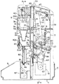
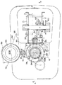
図1は、実施の形態に係るソフトクリームの盛り付け器の縦断側面図、図2は同縦断正面図、図3は同横断平面図である。1は基台で、この基台1上には支持フレームを構成する左右1対のサイドフレーム2,3が立設されている。4はサイドフレーム2,3の前面に取り付けられたフロントフレーム、また5はサイドフレーム2,3を覆って取り付けられたフレームカバーである。サイドフレーム2,3の上端には容器載置台としての受板6が前方に突出した状態で固定されており、この前方に突出した受板6の前端部には図3に示すように半円弧状に切り欠かれた凹欠部7が形成されている。凹欠部7と隣接する受板6の一方の前端部には支軸8が立設され、該支軸には被覆体としての容器ホルダ9が図2で鎖線で示す凹欠部7上のソフトクリーム押出し位置イと該位置から180°外方の実線で示すソフトクリーム容器10をセットする容器セット位置ロとに位置可能なようにベアリング11を介して回動可能に取り付けられている。
FIG. 1 is a longitudinal side view of a soft ice cream dispenser according to an embodiment, FIG. 2 is a longitudinal front view thereof, and FIG. 3 is a transverse plan view thereof. Reference numeral 1 denotes a base, on which a pair of left and
容器ホルダ9は常時容器セット位置ロに位置するようにワイヤ12とスプリング13により付勢されており、容器セット位置ロから押出し位置イへ位置させるときはこの付勢力に抗して手動で移動させる。前記付勢力により容器ホルダ9が極端に速いスピードで容器セット位置ロへ移動しないように支軸8の上端に速度緩衝用のダンパ15が設けられている。容器ホルダ9は図5にも示すように凹欠部7より大径で中心部に排出孔16を有する底板部9aと、該底板部の周縁部に立設された半円筒状のフード部9bと、底板部9a上に載置されてソフトクリーム容器10を受ける排出孔17付きホルダ部9cからなっている。ホルダ部9cは外周に縁18が設けられ、排出孔17の孔縁の下端には容器の載置時に底板部9aの排出孔16に嵌まる環状凸部19が設けられている。ホルダ部9cは底板部9aに対して着脱自在になっており、汚れたときは取り外して容易に清掃できる。
The
21は底板部9aの方形角部に設けられた係止片であり、容器ホルダ9を押出し位置イにセットしたときに受板6上のブラケット22にピン23により枢支されたフックレバー25の一端の係止爪26に係止し、位置決め固定されるようになっている。フックレバー25はレバー28の上端にピン29により上下に揺動自在に取り付けられている。レバー28は図示しないスプリングにより常時矢印ハ方向に付勢され、これによりフックレバー28の係止爪26が係止片21と係止する下向きとなるようになっている。レバー28の上端面と当接可能にフック解除ボタン30が設けられ、該ボタンを押すことによりレバー28を前記スプリングの付勢に抗して下動させ、フックレバー25の係止爪26を係止片21から外すことができるようになっている。レバー28の下端には後記ドックピン79と係合するL字状の係合部31が設けられている(図5参照)。
ソフトクリームが押し出されたソフトクリーム容器10が容器セット位置ロへ戻され、その容器を即座に取り除かないと、押出し切れずに容器内に残ったソフトクリームが滴り落ちる恐れがある。そのために図2,3に示すように容器セット位置ロの直下に受皿33を設けて、滴り落ちるソフトクリームを受けるようになっている。受皿33は上面に凹所33aを有し、側面に突設した取付部34に設けた嵌合凹部35をフレームカバー5の嵌合凸部36に嵌入することにより着脱可能に取り付けられるようになっている。したがって、この構成により受皿33が汚れたときは取り外して清掃することができる。
If the soft
受板6の後端部にはアームスタンド39が立設され、このアームスタンドの上端部にはハンマーレバー47の後端部がピン37により枢支されている。ハンマーレバー47の前端部には連結ピン38を介してスライダ40が取り付けられている。スライダ40は後端部が受板6に立設したガイド軸41に摺動自在に嵌挿され、かつ前端部の下面には押圧部材としての押圧ヘッド42がねじ43により高さ(押圧ヘッド42の下面との間隔)調整可能に取り付けられている。44は回り止めねじである。押圧ヘッド42の下面は押圧面42aに形成され、この押圧面でホルダ9c上に載置されるソフトクリーム容器10を押圧して内部に収納したソフトクリームをその下部排出口から下方に排出できるようになっている。ガイド軸41の上端にはアームスタンド39の上端とを連結する連結片45がねじ46により取り付けられている。48はピン37に介装されたねじりばねで、ハンマーレバー47を常時上方に付勢して押圧ヘッド42が図1のように位置するようになっている。
An
ハンマーレバー47の中間部にはハンマーカムレバー50の上端部がピン51により枢支されている。ハンマーカムレバー50は受板6に形成された穴52から下方に突出し、その下端部にはカムローラ53が取り付けられている。カムローラ53上方のハンマーカムレバー50には長孔55が切欠き形成され、該孔には駆動軸56がメタル案内筒部を介して摺動可能に配置されてその端部には押出しカム57がカムローラ53にその外周面で衝合して取り付けられている。サイドフレーム3から外方に突出した駆動軸56上にはスプロケット60が装着され、該スプロケットと下方に設置した正逆転駆動モータ61の軸上に装着されたスプロケット62間には無端チェーン63が装架され、モータ61を駆動することにより駆動軸56を回転し、カム57が矢印ニのように回転しながらカムローラ53上を摺動することによりハンマーカムレバー50を上下動できるようになっている。すなわち、カム57は回転径が大きくなるにつれて押圧ヘッド42を下降させ、最下端まで下降し、さらに回転をつづけ、切欠き凹部65にカムローラ53が落ち込むこととなるが、このとき押圧ヘッド42は最下端まで下降した後、一定ストローク上昇して駆動軸56に取り付けられた図示しないカムスイッチにより後記するモータ駆動用スイッチが作動されてモータ61を停止する往復回転運動をする。
An upper end portion of a
67は揺動レバーで、後端部がサイドフレーム2,3間に取り付けられた軸68に枢支され、中間部にカムローラ70が固定されている。このカムローラ70は駆動軸56に取り付けられた昇降カム71の外周面に衝合するようになっており、昇降カム71の回動により押し下げられ、これにより揺動レバー67を、軸68を中心に上下に揺動させる。73は受板6と揺動レバー67間に取り付けられ、揺動レバー67を常時上方に付勢するばねである。揺動レバー67の前端部には先端開口の凹溝74が形成され、該凹溝には上下動体75の上端側面に設けたガイドピン76が係合されている。上下動体75は取付部75aを介してフロントフレーム4から前面に突出するブラケット77を有し、該ブラケットとともに上下動体75とフロントフレーム4間に設けたベアリング78を介して上下に移動可能になっている。79は上下動体75の上端部に取り付けられたドックピンである。
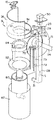
ブラケット77は側面略コ字状に形成されて、その前方であって、ホルダ部9cの中心の真下に相当する位置には中空の回転軸80が軸受81で支持されて縦向きに配設され、該回転軸の上端開口部には回転受皿82の下端軸部82aが挿入され、さらにこの回転受皿の取り付け用中空の軸部82bには受容器としてのコーン83を支持する環状のコーン取付台84の軸部が挿入され、かつばね85により図3の実線で示す位置(回転軸80の軸心)に常時位置可能なように配設されている。回転受皿82及びコーン取付台84はそれぞれ着脱自在になっていて、汚れたときは取り外して清掃することができる。コーン取付台84はコーン83の装着及び取外しに際してばね85に抗して図3の鎖線の位置まで回動して位置させることができるようになっている。回転軸80の下端部にはカムピン86が取り付けられ、このカムピンはフロントフレーム4の前面に配置した溝カムカバー87の壁に形成された傾斜カム溝88に摺動可能に係合されている。カムピン86がこのカム溝88の上端から下端まで移動する間に回転軸80、すなわちコーン取付台84を所定角度(この例では180°)回転させるようになっている。
The
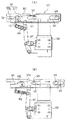
前記揺動レバー67は、図6に示すように断面凹状に形成され、後端にストッパ部が設けられた固定レバー部90と、断面L形に形成され、固定レバー部にその長手方向に移動可能に収容された移動レバー部91とを有している。移動レバー部91の移動は、軸68及びガイドピン93と係合する長孔94,95によってなされる。移動レバー部91にはソレノイド作動片97の先端が固定レバー部及び移動レバー部の各底壁に設けた孔を経て係合しており、固定レバー部90に取り付けられたソレノイド98の作動により、移動レバー部91が、その先端が固定レバー部90の先端と同じ位置(A)から所定長さ後退した位置(B)となるように移動される。位置(A)が後記するように自動盛付時の状態で、位置(B)が手動盛付時の状態である。自動盛付時の状態である位置(A)においては、ソレノイド98は不作動であり、ばね99の付勢によって当該位置が保持される。手動盛付時の状態である位置(B)においては、ソレノイド98が作動され、これによってばね99の付勢力に抗して引かれるソレノイド作動片97によって移動レバー部91が後退させられ、その前端部が固定レバー部90の前端部との間で凹溝74を形成しないようになり、凹溝74とガイドピン76とが離脱する。
As shown in FIG. 6, the
前記のように凹溝74は、この実施の形態では固定レバー部90の前端部に形成された切欠半部と、該切欠半部と対応する移動レバー部91の前端部に形成された切欠半部とにより形成されている。移動レバー部91は、レバー部本体91aと、該本体の前端に後端が軸101により枢支された前端部91bからなっている。前端部91bは、図8に示すように固定レバー部90の前端部と凹溝74を形成する第1の位置(実線位置)と、該位置から固定レバー部90の前端部方向の離れた第2の位置(鎖線位置)との間に屈曲可能になっている。102は軸101に介装されたばねであり、前端部91bが第1の位置にあるときその状態を保持するように付勢する。
As described above, the
前記において、ハンマーレバー47、ハンマーカムレバー50、カムローラ53、駆動軸56、駆動モータ61、揺動レバー67、カムローラ70、昇降カム71等は、押圧ヘッド42を上下動させる第1の作動機構を構成する。また、揺動レバー67の前端部の凹溝74とガイドピン76で係合した上下動体75、ブラケット77、回転軸80、回転受皿82、コーン取付台84等は、第1の作動機構と連動して上下動し、コーン取付台84を受板6の下方位置からさらに下方の所定位置へ移動する間に回転させる第2の作動機構を構成する。
In the above, the
図7は、この盛り付け器の所定位置に設けられる操作部104を示し、この操作部にはコーン83をコーン取付台84にセットするときに押すUPスイッチ105、自動盛付のときに押すDOWNスイッチ106、手動盛付のときに押すスイッチ107が設けられている。108は手動盛付のときに点灯するランプ、109は異常のときに点灯するランプ、110は電源入力により点灯するランプである。
FIG. 7 shows an
ソフトクリーム容器10は、詳細は図示省略したが、従来と同様に内部に1人ぶんのアイスクリームを密閉状態で収納し、上下方向に圧縮し易いようにジャバラ体からなる円錐状の中空本体と、該本体の一端開口部を覆って熱容着された蓋と、本体の他端壁部に形成された排出口を覆って張り付けられたシール片から構成されており、該排出口が下側となるようにホルダ9c上に載置される。
The soft
次に前記の作用を自動盛付時と手動盛付時に分けて説明する。 Next, the above-described operation will be described separately for automatic placement and manual placement.
自動盛付時には、図2のように容器ホルダ9が容器セット位置ロに位置した状態で、容器ホルダ9のホルダ部9c上にソフトクリーム容器10を排出口が下側となるように載置してセットした後、該容器ホルダ9を押出し位置イまで移動し、係止片21をフックレバー25の係止爪26に係止してフックし、ソフトクリーム容器10が押圧ヘッド42のほぼ直下に位置するようにセットする。これにより容器10は容器ホルダ9のフード部9bによってその前面側が覆われた状態となる。また、コーン取付台84にコーン83をセットしたうえで、操作部104のUPスイッチ105を押す、これにより第1の作動機構及び第2の作動機構が上動して、セットしたコーン83が上方のスタート位置にもたらされる。この状態を示すのが図1である。しかる後、操作部104のDOWNスイッチ106を押してモータ61を正転駆動すると、駆動軸56が回転し、これとともにカム57の回転によってハンマーカムレバー50が下方に引かれ、ハンマーレバー47が下方に揺動され、押圧ヘッド42の押圧面42aが容器10の上面に当ってこれを押圧し、内部に収納したアイスクリームを下部排出口から排出させる。そして押圧が終わると、押圧ヘッド42は一定ストローク上昇を始める。一方、駆動軸56の回転により昇降カム73も回転され、この昇降カムの回転によりその外周面と衝合したカムローラ70が次第に押し下げられ、これとともに揺動レバー67が下方へ揺動し、凹溝74でガイドピン76と係合する上下動体75を下動させる。
At the time of automatic assembling, the soft
前記のように上下動体75が下動すると、ブラケット77の回転軸80に取り付けられたガイドピン86がカム溝88に沿ってその上端から下端に向けて摺動し、このカム溝88を摺動する間に回転受皿82が所定角度回転させられる。そして図4のようにカム57の凹部65にカムローラ53が落ち込みしばらくすると、前記カムスイッチがオンして、モータ61の駆動が停止し、上下動体75は最下位にもたらされる。前記の上下動体75の下動と該上下動体75に取り付けられた回転受皿82の回転により、取付台84上のコーン83には容器10の排出口から排出されたアイスクリームが図4のように排出口の形状に対応した形状の、ねじれ巻きにされた状態に盛り付けられる。また上下動体75が最下位となると、ドックピン79が係合部31に当たってレバー28を押し下げ、これによりフックレバー25が揺動して係止片21が係止爪26から外れる。これと同時に押圧ヘッド42はつぶれた容器10から所定量上昇し、図4に示すように隙間Sを開き、かつ容器ホルダ9はスプリング13により押出し位置イから容器セット位置ロへ自動的に移動されることになる。したがって、もし容器10の中に残存したソフトクリームが滴り落ちてもその下方に設けられている受皿33で受け止められる。盛り付けが終了した後は、コーン取付台84をばね85に抗して回動して図3の鎖線で示す位置に位置させた上、コーン83を取り外す。盛り付けたコーン83を取り外した後、あるいは取り外したコーン取付台84に新たなコーンをセットした後、UPスイッチ105を押してモータ61を逆転駆動すると、駆動軸56が前記とは逆に回転し、これに伴いカム57等の機構も逆に作動して、揺動レバー67がばね73により上方へ揺動し、これとともに上下動体75も上動する。またばね48によりハンマーレバー47も上方へ揺動し、これにより盛り付け器は再び図1,2に示す元の待機状態になる。
When the vertically moving
自動盛付に代え、手動による盛付を行う手動盛付時には、前記の待機状態で操作部104のスイッチ107を押す。これによりランプ108が点灯して手動盛付に切り替えられたことがわかるとともに、図6(B)に示すようにソレノイド98が作動してソレノイド作動片97がばね99の付勢力に抗して引かれる。これにより、移動レバー部91が後退させられ、その前端部91bが固定レバー部90の前端部との間で凹溝74を形成しないようになり、凹溝74とガイドピン76とが離脱する。
When manual placement is performed instead of automatic placement, the
しかる後、操作部104のUPスイッチ105を押すと、第1の作動機構が作動して押圧ヘッド42を上動させるが、第2の作動機構はガイドピン76が揺動レバー67の凹溝74と係合しなくなるので、これと連動せず、回転受皿82の取付台84は下方位置のままに置かれることになる。したがって、その後においての押圧作動に際しては、例えばデザート等が入っている容器を一方の手に持ってアイスクリーム排出口に位置させるとともに、他方の手で操作部104のDOWNスイッチ106を押すと、前記と同様に第1の作動機構が作動して押圧ヘッド42により容器10を押圧し、容器10から排出されるソフトクリームを手で持った容器で好みに応じて受けることができ、自由な盛付をすることが可能となる。
After that, when the
前記において間違って揺動レバー67が上方位置にあるときに電源が切れたりしてソレノイド98が不作動となり、移動レバー部91がばね99により前進させられてしまう場合、自動盛付で揺動レバー67が下動すると、移動レバー部91の前端部91b下面がガイドピン76に当り、凹溝74とガイドピン76との係合が出来ない状態となる。しかし、この実施の形態ではガイドピン76にあたったときに移動レバー部91の前端部91bがばね102に抗して離れるように屈曲してガイドピン76を凹溝74に受け入れる。ガイドピン76が凹溝74に係合したら、前端部91bはばね102により元の位置に復帰して戻る。このように異常動作させられたときでも移動レバー部91の前端部91bがばね102で逃げてガイドピン76と凹溝74が再係合可能なように安全策が講じられている。
In the above case, when the
前記実施の形態は特に好ましい一例を示したにすぎない。例えば揺動レバー67は必ずしも図示したような構成としなくともよく、同効のものであれば図示した以外の構成としてもよいことは言うまでもない。また、作動部材として示したソレノイド98も一例であり、ほかの部材で代替してもよい。
The above embodiment only shows a particularly preferable example. For example, the
1 基台 2,3 サイドフレーム
4 フロントフレーム 5 フレームカバー
6 受板 7 凹欠部
8 支軸 9 容器ホルダ
10 ソフトクリーム容器 33 受皿
67 揺動レバー 74 凹溝(係合部)
75 上下動体 76 ガイドピン(係合部)
90 固定レバー部 91 移動レバー部
93 ガイドピン 94,95 長孔
97 ソレノイド作動片 98 ソレノイド(作動部材)
99 ばね 91a レバー部本体
91b 前端部 101 軸
102 ばね(付勢部材) 104 操作部
105 UPスイッチ 106 DOWNスイッチ
107 スイッチ 108,109,110 ランプ
DESCRIPTION OF SYMBOLS 1
10 Soft
67
75
90
93
97
99
91b Front end 101 axis
102 Spring (biasing member) 104 Operating section
105
Claims (2)
第1の作動機構は、上下に揺動する揺動レバーを有し、第2の作動機構は、上下に移動する上下動体を有し、前記揺動レバーの前端部に設けた先端開口の凹溝と前記上下動体の上端側面に設けたガイドピンが係脱可能になっており、また前記揺動レバーは、固定レバー部と、該レバー部の長手方向に移動可能となった移動レバー部とを有し、固定レバー部の前端部に凹溝を形成する切欠半部が形成され、該切欠半部と対応する移動レバー部の前端部に凹溝を形成する切欠半部が形成されており、前記凹溝とガイドピンを自動盛付時に係合し、手動盛付時に離脱するように係脱させる作動部材が設けられ、該作動部材を作動するための操作スイッチが設けられていることを特徴とするソフトクリーム状食品の盛り付け器。 A container mounting table; a pressing member arranged to be movable up and down with respect to the mounting table; a first operating mechanism for moving the pressing member up and down; and a vertical movement in conjunction with the operating mechanism; A second actuating mechanism for rotating the part while moving the unit from a lower position of the mounting table to a predetermined position further below, and an operation switch for actuating the first actuating mechanism. Software that lowers the pressing member by operating the operating mechanism, presses the container placed on the mounting table, and discharges the soft cream-like food stored inside from the outlet toward the food receiving part below In the cream food applicator,
The first actuating mechanism has a swing lever that swings up and down, and the second actuating mechanism has a vertically moving body that moves up and down, and a recess in a tip opening provided at the front end of the swing lever. groove and the and guide pins provided on the upper end side of the vertical movement body is enabled disengaged and said rocking lever includes a fixed lever portion, and a movable lever portion which is movable in the longitudinal direction of the lever portion A notch half is formed in the front end of the fixed lever part, and a notch half is formed in the front end of the moving lever part corresponding to the notch half. An operation member for engaging and disengaging the concave groove and the guide pin at the time of automatic assembling and disengaging so as to be detached at the time of manual embedding is provided, and an operation switch for operating the operation member is provided. Dispenser for soft cream food.
Priority Applications (1)
| Application Number | Priority Date | Filing Date | Title |
|---|---|---|---|
| JP2005121772A JP4030552B2 (en) | 2005-04-20 | 2005-04-20 | Soft ice cream food bowl |
Applications Claiming Priority (1)
| Application Number | Priority Date | Filing Date | Title |
|---|---|---|---|
| JP2005121772A JP4030552B2 (en) | 2005-04-20 | 2005-04-20 | Soft ice cream food bowl |
Publications (2)
| Publication Number | Publication Date |
|---|---|
| JP2006296273A JP2006296273A (en) | 2006-11-02 |
| JP4030552B2 true JP4030552B2 (en) | 2008-01-09 |
Family
ID=37465141
Family Applications (1)
| Application Number | Title | Priority Date | Filing Date |
|---|---|---|---|
| JP2005121772A Expired - Fee Related JP4030552B2 (en) | 2005-04-20 | 2005-04-20 | Soft ice cream food bowl |
Country Status (1)
| Country | Link |
|---|---|
| JP (1) | JP4030552B2 (en) |
Families Citing this family (3)
| Publication number | Priority date | Publication date | Assignee | Title |
|---|---|---|---|---|
| GB0916618D0 (en) * | 2009-09-22 | 2009-11-04 | Mcgill Tech Ltd | Apparatus for dispensing food product |
| KR101980837B1 (en) * | 2018-02-07 | 2019-05-21 | 조재원 | Extrude apparatus for ice cream |
| KR102025882B1 (en) * | 2018-06-01 | 2019-11-04 | 조재원 | Extrude apparatus for ice cream |
-
2005
- 2005-04-20 JP JP2005121772A patent/JP4030552B2/en not_active Expired - Fee Related
Also Published As
| Publication number | Publication date |
|---|---|
| JP2006296273A (en) | 2006-11-02 |
Similar Documents
| Publication | Publication Date | Title |
|---|---|---|
| CN116782770B (en) | Frozen dessert dispenser and cartridge | |
| JP5148693B2 (en) | Improvements in or related to beverage adjustment machines | |
| US12439927B2 (en) | Preparation station for a fast food restaurant | |
| US11045015B2 (en) | Self-service device for taking tableware | |
| JP4030552B2 (en) | Soft ice cream food bowl | |
| JP2742018B2 (en) | Paste for kneaded products | |
| JP2005533977A (en) | Drive mechanism | |
| JP2003285900A (en) | Beverage stock feeder and beverage maker | |
| KR101980837B1 (en) | Extrude apparatus for ice cream | |
| JP3391724B2 (en) | Soft cream-like food platter | |
| JP5583462B2 (en) | Raw material unloader | |
| JP2999197B1 (en) | Support for receptor | |
| JP6443114B2 (en) | Beverage ingredient dispensing device | |
| JP6447221B2 (en) | Bag container opening device | |
| JP3955051B2 (en) | Semi-solid food dispensing container, dispensing device and dispensing method | |
| CN118055899A (en) | Strip feeding device, in particular for a blender dispenser in a beverage vending machine | |
| US5318196A (en) | Coffee stirrer dispenser | |
| JP5583461B2 (en) | Raw material unloader | |
| EP1186240B1 (en) | Frozen dessert dispenser | |
| KR20170009244A (en) | An ice shaving machine having detachable cutting means | |
| JP2005245588A (en) | Powder tea discharger for beverages | |
| JP2005265398A (en) | Dispenser | |
| JP2016150787A (en) | Bag container opening device | |
| JP2001152529A (en) | Flush toilet stool device | |
| US2312456A (en) | Butter dispenser |
Legal Events
| Date | Code | Title | Description |
|---|---|---|---|
| A977 | Report on retrieval |
Free format text: JAPANESE INTERMEDIATE CODE: A971007 Effective date: 20070712 |
|
| A131 | Notification of reasons for refusal |
Free format text: JAPANESE INTERMEDIATE CODE: A131 Effective date: 20070731 |
|
| A521 | Written amendment |
Free format text: JAPANESE INTERMEDIATE CODE: A523 Effective date: 20070822 |
|
| TRDD | Decision of grant or rejection written | ||
| A01 | Written decision to grant a patent or to grant a registration (utility model) |
Free format text: JAPANESE INTERMEDIATE CODE: A01 Effective date: 20070925 |
|
| A61 | First payment of annual fees (during grant procedure) |
Free format text: JAPANESE INTERMEDIATE CODE: A61 Effective date: 20071016 |
|
| R150 | Certificate of patent or registration of utility model |
Free format text: JAPANESE INTERMEDIATE CODE: R150 |
|
| FPAY | Renewal fee payment (event date is renewal date of database) |
Free format text: PAYMENT UNTIL: 20101026 Year of fee payment: 3 |
|
| FPAY | Renewal fee payment (event date is renewal date of database) |
Free format text: PAYMENT UNTIL: 20101026 Year of fee payment: 3 |
|
| FPAY | Renewal fee payment (event date is renewal date of database) |
Free format text: PAYMENT UNTIL: 20111026 Year of fee payment: 4 |
|
| FPAY | Renewal fee payment (event date is renewal date of database) |
Free format text: PAYMENT UNTIL: 20111026 Year of fee payment: 4 |
|
| FPAY | Renewal fee payment (event date is renewal date of database) |
Free format text: PAYMENT UNTIL: 20121026 Year of fee payment: 5 |
|
| FPAY | Renewal fee payment (event date is renewal date of database) |
Free format text: PAYMENT UNTIL: 20121026 Year of fee payment: 5 |
|
| FPAY | Renewal fee payment (event date is renewal date of database) |
Free format text: PAYMENT UNTIL: 20131026 Year of fee payment: 6 |
|
| R250 | Receipt of annual fees |
Free format text: JAPANESE INTERMEDIATE CODE: R250 |
|
| R250 | Receipt of annual fees |
Free format text: JAPANESE INTERMEDIATE CODE: R250 |
|
| R250 | Receipt of annual fees |
Free format text: JAPANESE INTERMEDIATE CODE: R250 |
|
| R250 | Receipt of annual fees |
Free format text: JAPANESE INTERMEDIATE CODE: R250 |
|
| LAPS | Cancellation because of no payment of annual fees |