JP4028072B2 - Liquid supply device - Google Patents
Liquid supply device Download PDFInfo
- Publication number
- JP4028072B2 JP4028072B2 JP08867798A JP8867798A JP4028072B2 JP 4028072 B2 JP4028072 B2 JP 4028072B2 JP 08867798 A JP08867798 A JP 08867798A JP 8867798 A JP8867798 A JP 8867798A JP 4028072 B2 JP4028072 B2 JP 4028072B2
- Authority
- JP
- Japan
- Prior art keywords
- tube
- liquid
- liquid supply
- flow
- flow rate
- Prior art date
- Legal status (The legal status is an assumption and is not a legal conclusion. Google has not performed a legal analysis and makes no representation as to the accuracy of the status listed.)
- Expired - Lifetime
Links
Images


Classifications
-
- A—HUMAN NECESSITIES
- A61—MEDICAL OR VETERINARY SCIENCE; HYGIENE
- A61M—DEVICES FOR INTRODUCING MEDIA INTO, OR ONTO, THE BODY; DEVICES FOR TRANSDUCING BODY MEDIA OR FOR TAKING MEDIA FROM THE BODY; DEVICES FOR PRODUCING OR ENDING SLEEP OR STUPOR
- A61M5/00—Devices for bringing media into the body in a subcutaneous, intra-vascular or intramuscular way; Accessories therefor, e.g. filling or cleaning devices, arm-rests
- A61M5/14—Infusion devices, e.g. infusing by gravity; Blood infusion; Accessories therefor
- A61M5/141—Infusion devices, e.g. infusing by gravity; Blood infusion; Accessories therefor with capillaries for restricting fluid flow
-
- A—HUMAN NECESSITIES
- A61—MEDICAL OR VETERINARY SCIENCE; HYGIENE
- A61M—DEVICES FOR INTRODUCING MEDIA INTO, OR ONTO, THE BODY; DEVICES FOR TRANSDUCING BODY MEDIA OR FOR TAKING MEDIA FROM THE BODY; DEVICES FOR PRODUCING OR ENDING SLEEP OR STUPOR
- A61M5/00—Devices for bringing media into the body in a subcutaneous, intra-vascular or intramuscular way; Accessories therefor, e.g. filling or cleaning devices, arm-rests
- A61M5/14—Infusion devices, e.g. infusing by gravity; Blood infusion; Accessories therefor
- A61M5/142—Pressure infusion, e.g. using pumps
- A61M5/145—Pressure infusion, e.g. using pumps using pressurised reservoirs, e.g. pressurised by means of pistons
- A61M5/148—Pressure infusion, e.g. using pumps using pressurised reservoirs, e.g. pressurised by means of pistons flexible, e.g. independent bags
- A61M5/152—Pressure infusion, e.g. using pumps using pressurised reservoirs, e.g. pressurised by means of pistons flexible, e.g. independent bags pressurised by contraction of elastic reservoirs
Description
【0001】
【発明の属する技術分野】
本発明は、液体収納部内に収納された液体を、持続的に微量ずつ供給する液体供給装置に関する。たとえば、人体や動物などの生体に薬液や輸液剤などを持続的に供給するため、あるいは、植物に水、栄養剤(液)、薬液(防虫液)などを持続的に供給するため、さらには、魚用水槽に抗生物質などの薬液、餌(液体)や水草用栄養剤(液)などを持続的に供給するためなどに用いられる液体供給装置に関する。
【0002】
【背景技術】
たとえば、人体に薬液を持続的に微量ずつ注入する薬液注入装置では、微細な内径で、かつ、導管機能と流量調節機能とを有する微細径チューブを用い、このチューブ内を薬液を通すことによって薬液を持続的に微量ずつ人体に注入する構造である。
従来、導管機能と流量調節機能とを有する微細径チューブを用いた薬液注入装置では、流量を変更する場合、チューブの交換によって行っていたが、これでは流量変更を迅速に行えないという不具合があった。
【0003】
そこで、このような不具合を解消するものとして、薬液収納部の流出口に通液量が異なる2本のチューブを介して流量切換器を接続した構造(特開平6−121835号公報参照)、あるいは、薬液収納部と人体とを接続するチューブの途中に流量切換器を挿入した構造(特公平9−225028号公報参照)などが提案されている。
【0004】
前者の流量変更構造は、薬液ポンプの流出口を二股に分岐するとともに、その各分岐口に2本のチューブの一端を接続し、この2本のチューブの他端にいずれか一方のチューブの流路を選択的に開閉する流量切換コックを接続した構造である。
【0005】
後者の流量変更構造は、本体ケースに薬液の流入部および流出部を形成し、この流入部および流出部を、本体ケース内の流路分岐部から分岐された複数のチューブを介して接続するとともに、流路分岐部に各チューブを選択的に開閉する操作栓を設けた構造において、本体ケース内の前記流路分岐部の周囲に収納スペースを形成し、この収納スペース内に前記複数のチューブを前記流路分岐部の回りに旋回させた状態で収納した構造である。
【0006】
【発明が解決しようとする課題】
しかしながら、従来の構造では、次のような課題がある。
前者の構造では、2本のチューブが別体であるため、携帯時に取扱ずらく、チューブが邪魔になるという欠点がある。とくに、各チューブは、流量調節機能を確保するためにある程度の長さを備えているから、取扱ずらく、収納にも邪魔になる。
後者の構造では、チューブの途中に流量切換器がるため、局部的に太くなり、取扱性に欠けるという欠点がある。
【0007】
本発明の目的は、このような従来の欠点を解消し、携帯や収納に便利で取扱性に優れ、しかも、流量変更を簡易かつ他段階にできる液体供給装置を提供することにある。
【0008】
【課題を解決するための手段】
本発明の液体供給装置は、上記目的を達成するため、液体収納部内に収納された液体を液体供給チューブを通して供給する液体供給装置において、前記液体供給チューブは、所定長さ寸法に形成され、かつ、その長手方向に沿って互いに平行な複数の流路を内部に有し、前記液体収納部に収納された液体を前記複数の流路に選択的に流通させる流路選択手段を備え、前記流路選択手段は、流入口に前記液体供給チューブを接続した流入側ケースと、流出口に流出側チューブを接続した流出側ケースと、これら流入側ケースおよび流出側ケースの間に支軸を中心として回転可能にかつ互いに接して設けられた複数枚の流路開閉プレートとを有し、前記流入側ケースには、前記液体供給チューブの複数の流路が前記支軸を中心とする同一円周上に配置され、前記各流路開閉プレートは、前記支軸を中心とする同一円周上でかつ前記各流路に連通するように対応して形成された複数の通液孔と、回転角位置に応じて前記いずれか1つの流路のみを閉塞できる閉塞領域とを有することを特徴とする。
【0009】
本発明においては、液体収納部内に収納された液体を、複数の流路に選択的に流通させることができるから、流路の選択によって流量を変えることができる。たとえば、各流路の通液量が同じ場合には、選択する流路の数を選択することによって、流量を変更することができる。従って、流量の変更を簡易にかつ他段階に行うことができる。しかも、複数の流路は1本の液体供給チューブ内に設けられているから、携帯や収納時にも邪魔になることがなく、取扱性が低下することもない。
また、各流路開閉プレートを回転させながら、その閉塞領域によって複数の流路を選択的に閉塞することにより、使用する流路を選択できるから、簡単な操作で、流量変更を行うことができる。
【0010】
ここで、複数の流路は、互いに通液量が同じでもよいが、互いに通液量が異なるようにすれば、1つの流路を選択するだけで、流量の変更ができる。
この際、流路選択手段を、液体収納部内に収納された液体を、複数の流路のうち少なくとも1つ以上の流路に選択的に流通させ手段を備える構成とすれば、選択する流路の数や、通液量の異なる流路の組合せを選択することによって、流量を微細にかつ多段階に変更することができる。
【0012】
以上において、前記複数の流路は、断面開口形状が異形で所定長さを有する熱可塑性樹脂製のチューブ素子により構成されていることが望ましい。
【0013】
【発明の実施の形態】
以下、本発明の一実施形態を図面に基づいて説明する。
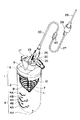
本実施形態は人体に薬液を注入する薬液注入装置に適用した例である。図1は斜視図、図2は断面図である。これらの図において、1は保護ケースで、プラスチックやガラスなどの透明な材料によって有底筒状に形成された筒体2と、ポリプロピレンなどの材料によって形成され前記筒体2の開口端に嵌合された蓋体5とから構成されている。
【0014】
前記筒体2は、内周部が円形を除く異形断面を有する形状、ここでは、断面形状が楕円形状(図3参照)の有底筒状に形成されているとともに、開口端側内周壁に突起3が、外周壁に目盛4がそれぞれ設けられている。目盛4としては、筒体2の上下方向中間位置から底部に向かって薬液収納量(後述するゴム様弾性膜11内の薬液収納量)をcc単位で表す「0」「20」「40」「60」の偶数目盛4Aと、これらの間の「10」「30」「50」を表す奇数目盛4Bとが設けられている。
【0015】
前記蓋体5には、その外周壁面に前記筒体2の突起3に係合する係合凹部6が形成されているとともに、上壁略中央位置に前記筒体2内に向かって延びる細長円筒状の液体導入管としての薬液導入管7および通気孔9がそれぞれ設けられている。薬液導入管7は、両端が開口され、かつ、周面に内外を連通させる複数条のスリット8を有する。通気孔9には、図4に示すように、保護ケース1の内外の気体(空気)を流通させることができ、かつ、薬液の流通を阻止する撥水通気フィルタ9Aが取り付けられている。撥水通気フィルタ9Aとしては、たとえば、合成繊維束を撥水処理した耐薬品性のものが好ましい。
【0016】
前記薬液導入管7には、有底チューブ状ゴム様弾性膜11が密着する状態で被嵌され、かつ、その開口端縁がピンチ12により保持されている。ここに、薬液導入管7の外径および長さは、ゴム様弾性膜11の収縮時の内径および長さに略等しい寸法に形成されている。ゴム様弾性膜11内には、最大60ccの薬液が収納できるようになっている。ちなみに、癌疼痛用の薬液の場合、通常1日に20cc程度の注入であるから、略3日分の薬液が収納できるようになっている。薬液の注入、収納に伴って、ゴム様弾性膜11は膨張されるが、その外周にはゴム様弾性膜11の膨張に伴って伸長するスプリング10が配置されている。スプリング10は、たとえば、線径0.6〜0.8mm程度の線材によって構成され、かつ、上端が前記蓋体5に係止されているとともに、直径が下方へ向かうに従って次第につぼまった螺旋状に巻かれ、さらに最下端がゴム様弾性膜11を介して薬液導入管7の先端に当接されている。
【0017】
前記ゴム様弾性膜11は、高靱性で伸縮性に富み、薬液などの作用によっても容易に損傷しない耐薬品性の材料から作られることが好ましく、特に、透明あるいは半透明の材料が好ましい。たとえば、市販のシリコンゴムやラテックスゴムなどが好適である。また、厚みは0.4mm程度である。ゴム様弾性膜11に薬液を収納したときの収縮力は、1000〜7000mm水柱の圧力が好ましい。通常、人体静脈は60mm水柱先後であるから、これ以上の圧力があれば患者に注入できる。ゴム様弾性膜11の収縮力が1000mm水柱以下では、コントロールが困難となり、7000mm水柱以上では、ゴム様弾性膜11内にシリンジから薬液を注入するのが人の力では困難になるからである。しかし、これに限定されるものではない。
【0018】
また、前記薬液導入管7の上部位置(蓋体5)には、前記ゴム様弾性膜11内に薬液を注入する液体流入孔としての流入孔19と、前記ゴム様弾性膜11内に収納された薬液を流出する液体流出孔としての流出孔18とが近接してV字状に設けられている。つまり、蓋体5には、流入孔19と、流出孔18と、薬液導入管7とが略Y字状にかつ互いに連通して設けられている。前記流入孔19内には、外部から薬液導入管7への流入を許容しかつ薬液導入管7から外部への流出を阻止する逆止弁13が設けられている。逆止弁13は、流入孔19内に埋設されかつ途中に弁座14を有する弁筒15と、この弁筒15内に進退自在に収納され弁座14を開閉するシリコンゴムなどからなる耐薬品性の弁棒16とを備える。なお、弁筒15の外端部には、キャップ17が着脱自在に装着できるようになっている。また、前記流出孔18の周囲には、三方弁20を着脱自在に係合させる螺旋溝18Aが形成されている。三方弁20は、3つの切換口21A,21B,21Cを有する弁体22と、流路を切り換えるコック23とを含んで構成されている。
【0019】
前記三方弁20の切換口21Cには、導管機構および流量調節機能を有する液体供給チューブ30の一端に設けられたコネクタ25が着脱可能に接続されている。コネクタ25の内部には、薬液内の塵埃などを除去するフィルタ26が収納されている。チューブ30の他端には流路選択手段としての流量切換器40が接続され、その流量切換器40には単一の流路を内部に有する流出側チューブ27を介してコネクタ25と同様なコネクタ28が固着されている。コネクタ28の先端には人体装着器具としての注射針29が着脱可能に取り付けられている。従って、液体供給チューブ30、流量切換器40およびチューブ27を介して、ゴム様弾性膜11内と人体装着器具としての注射針29とが連結されている。
【0020】
液体供給チューブ30に用いられるチューブは、所定長さ寸法に形成され、かつ、その長手方向に沿って互いに平行な複数の流路を内部に有する。すなわち、図5に示すように、所定長さ寸法に形成され、かつ、通液量の異なる流路31A,32A,33A,34Aを有する熱可塑性樹脂製の複数本(ここでは、4本)のチューブ素子31,32,33,34を束ね、その外周を被覆材35で一体的に被覆した構造である。
【0021】
ここで、各チューブ素子31〜34は、単層チューブでもよく、補強、取扱いを考慮して被覆したチューブでもよい。また、チューブ素子31〜34の材料としては、ポリプロピレン(PP)、ポリエチレン(PE)、ポリアセタール(POM)、ポリカーボネート(PC)、ABS、ポリアミド樹脂、ポリスチレン(PS)などが使用できるが、透明のものが好ましい。また、被覆するときの被覆材は、柔軟性のあるものが好ましく、熱可塑性樹脂エラストマーを用いることができ、ポリオレフィン(LDPE,LLDPE)系エラストマー、熱可塑性ポリウレタンエラストマー、軟質塩化ビニル樹脂、EVAなどが使用できる。
【0022】
また、チューブ素子31〜34の断面開孔形状は、従来の流量制御手段のように円形の開孔ではなく、異形開孔とされ、そのいくつかの例が図6に示されている。
図6において、(A)に示されるチューブ素子31〜34の開孔36Aは、円形の基礎孔の内壁からその中心に向かって異なる2種の樹枝状の突起が交互に3つづつ突出した形状とされている。
(B)に示されるチューブ素子31〜34の開孔36Bは、チューブ素子31〜34の中心から半径方向に120度等配位置で略矩形の溝が延長され、全体として略Y字状とされ、かつ、その内壁に凹凸が形成された形状とされている。
(C)に示されるチューブ素子31〜34の開孔36Cは、(B)の内壁から凹凸を除き、かつ、各矩形の半径方向の長さが短くなった形状とされている。
(D)に示されるチューブ素子31〜34の開孔36Dは、円形の基礎孔の内壁からその中心に向かって細長い三角形状及び円形の突起が交互に3つづつ突出された形状とされている。
(E)に示されるチューブ素子31〜34の開孔36Eの形状は、(A)の形状における樹枝状突起の形状を少し変形させるとともに、基礎孔の内壁に内歯歯車状の凹凸を設けた形状である。
このようなチューブ素子31〜34の異形開孔は、その開孔内周縁寸法/断面開孔面積の平方根で示される異形度の値が7以上で異形効果も顕著になり、上記各開孔36A〜36Eはいずれも異形度が7以上と大きくされている。
【0023】
ちなみに、以上のような微細な異形開孔形状のチューブ素子31〜34の製造方法は、たとえば、特開昭51-21927号に記載のようなダイスを用いて成形できる。すなわち、チューブ素子31〜34の外径に略等しい範囲内に多数の樹脂導入孔を有するとともに、開孔36A〜36Eに相当する部分には孔を形成しないモノフィラメント用ダイスを用い、この導入孔から溶融樹脂モノフィラメントを押し出し、この多数の接近したモノフィラメントを融着させ、微細な異形開孔形状のチューブ素子31〜34を得るものであるが、チューブ素子31〜34の製法は、これに特定されるものではない。
【0024】
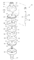
前記流量切換器40は、図7および図8に示すように、流入口(図中上端)に前記液体供給チューブ30を接続した流入側ケース41と、これとは反対側の流出口(図中下端)に前記チューブ27を接続した流出側ケース42と、この各ケース41,42の開口端に装着された保持プレート43,44と、この保持プレート43,44間の中心に掛け渡された支軸45と、この支軸45を中心として回転可能かつ前記保持プレート43,44の間に互いに接して設けられた4枚の流路開閉プレート46,47,48,49とを備える。なお、これらの材料としては、ポリエチレン(PE)、ポリカーボネート(PC)、ポリプロピレン(PP)などを用いることができる。
【0025】
各保持プレート43,44および各流路開閉プレート46〜49には、前記支軸45を中心とする同一円周上に4つの通液孔51,52,53,54が72度間隔でそれぞれ形成されている。なお、流路開閉プレート46〜49の通液孔51,54の間には、回転角位置に応じていずれか1つの流路31A〜34Aのみを閉塞できる閉塞領域55が形成されている。
保持プレート43の各通液孔51〜54には、前記液体供給チューブ30の各チューブ素子31〜34が接続されている。
【0026】
支軸45と各流路開閉プレート46〜49との間には、各流路開閉プレート46〜49の通液孔51〜54や閉塞領域55が保持プレート43,44の通液孔51〜54に順次対応する角度毎に、各流路開閉プレート46〜49を位置決めするための回転節度機構56が設けられている。回転節度機構56は、前記支軸45の各流路開閉プレート46〜49と対向する位置にばね57によって外側へ突出するように付勢されたボール58と、各流路開閉プレート46〜49の内周面に72度間隔で形成され前記ボール58が選択的に係合する係合溝59とから構成されている。
【0027】
次に、本実施形態の使用法につき説明する。
ゴム様弾性膜11内に薬液を収納するにあたり、図9に示されるように、キャップ17を逆止弁13の弁筒15から外し、薬液を収容したシリンジ61の先端を逆止弁13の弁筒15内に挿入する。この状態でシリンジ61内の薬液を押し出すと、薬液は逆止弁13を通ってゴム様弾性膜11を膨らませながらゴム様弾性膜11内に収納される。このとき、ゴム様弾性膜11の膨張に伴ってスプリング10も伸長するから、そのスプリング10の先端位置と対応する目盛4の値からゴム様弾性膜11内に収納された薬液の量を把握できる。
【0028】
やがて、ゴム様弾性膜11は保護ケース1の筒体2の内周壁に接する。このとき、図10に示すように、保護ケース1の断面形状は楕円形状に形成されているから、ゴム様弾性膜11の保護ケース1との接触面積を円形のものと比べ少なくできる。また、保護ケース1内での空気の流れを確保できるから、筒体2内の空気はゴム様弾性膜11の膨張に伴い、撥水通気フィルタ9Aを通って外部へ放出される。従って、薬液を持続的に微量ずつ正確に供給できるとともに、通気孔9の取付位置も制限されることがない。薬液の収納後、シリンジ61の先端を逆止弁13から引き抜くと、逆止弁13の弁座14は閉じられる。従って、ゴム様弾性膜11内の薬液が外部に漏出することがない。
【0029】
次に、チューブ27の先端のコネクタ28に注射針29を取付け、この注射針29を人体に装着した後、三方弁20のコック23を開放すれば、液体供給チューブ30、流量切換器40およびチューブ27を通って微少流量づつ順次薬液が人体内に注入される。ちなみに、本発明の微少流量とは、0.8ml/hr程度の使用が多いが、異形開孔形状、長さおよび薬液粘度により任意に特定でき、この流量に限定するものではない。
【0030】
ここで、流量を変更するには、流量切換器40の各流路開閉プレート46〜49を回転させて行う。
たとえば、流路開閉プレート46〜49を回転させ、図11(A)の状態にすると、保持プレート43,44および各流路開閉プレート46〜49の通液孔51〜54が全て連通しているから、流量は各チューブ素子31〜34の流路31A〜34Aの通液量の和となる。たとえば、チューブ素子31〜34の流路31A〜34Aの通液量を、2.0ml/hr、0.8ml/hr、0.7ml/hr、0.5ml/hrとすると、流量は4.0ml/hrとなる。
また、図11(B)の状態にすると、各流路開閉プレート46〜49の通液孔を通じて、保持プレート43,44の通液孔54のみが連通するから、流量はチューブ素子34の流路34Aの通液量となる。つまり、流量は0.5ml/hrとなる。
【0031】
このようにして、必要に応じて流量を変更しながら、ゴム様弾性膜11内の薬液が全て人体内に注入されたら、前述と同様にしてゴム様弾性膜11内に薬液を収納し、前述の動作を繰り返す。なお、注射針29を人体に装着する前にゴム様弾性膜11内のエア抜きを行うには、保護ケース1を蓋体5側を上にして垂直に立て、コック23を開放し、針先から薬液が流出するまで放置すればよい。
【0032】
上述した実施形態によれば、液体供給チューブ30として、所定長さ寸法に形成され、かつ、その長手方向に沿って互いに平行な複数の流路31A〜34Aを内部に有するチューブを用いるとともに、薬液をこれらの流路31A〜34Aに選択的に流通させる流量切換器40を設けたので、流量切換器40によって薬液を複数の流路31A〜34Aに選択的に流通させることができる。ここで、各流路31A〜34Aの通液量を互いに異ならせてあるから、流路31A〜34Aの選択によって流量を変更することができる。従って、流量の変更を簡易に行うことができる。
【0033】
しかも、複数の流路31A〜34Aは1本の液体供給チューブ30内に設けられているから、携帯や収納時にも邪魔になることがなく、取扱性が低下することもない。
【0034】
また、流量切換器40は、液体供給チューブ30を接続した流入側ケース41および流出側ケース42と、このケース41、42の開口端に装着された保持プレート43,44と、この保持プレート43,44間に支軸45を中心として回転可能にかつ互いに接して設けられた4枚の流路開閉プレート46〜49とを備える構成とし、各保持プレート43,44および各流路開閉プレート46〜49には、支軸45を中心とする同一円周上に前記流路31A〜34Aに対応して複数の通液孔51〜54を形成するとともに、各流路開閉プレート46〜49の通液孔51、54間に閉塞領域55を設けてあるから、各流路開閉プレート46〜49を回転させながら、その閉塞領域55によって複数の流路31A〜34Aを選択的に閉塞することにより、使用する流路31A〜34Aを選択できるから、簡単な操作で、流量変更を行うことができる。
【0035】
また、選択する流路の数や、通液量の異なる流路の組合せを選択することによって、流量を微細に多段階に変更することができる。ちなみに、本実施形態において、たとえば、チューブ素子31〜34の流路31A〜34Aの通液量を、2.0ml/hr、0.8ml/hr、0.7ml/hr、0.5ml/hrとすると、流量を、最小流量0.5ml/hr〜最大流量4ml/hrの範囲で、微細にかつ他段階に流量変更することができる。
【0036】
また、支軸45と各流路開閉プレート46〜49との間に回転節度機構56を設けたので、各流路開閉プレート46〜49を節度をもって所定角度(72度)位置で位置決めすることができる。従って、各流路31A〜34Aに対して、各流路開閉プレート46〜49の通液孔51〜54および閉塞領域55を正確に対応させることができる。よって、流量変更が正確にできる。
【0037】
また、回転節度機構56は、支軸45の各流路開閉プレート46〜49と対向する位置にばね57によって外側へ突出するように付勢されたボール58と、各流路開閉プレート46〜49の内周面に72度間隔で形成され前記ボール58が選択的に係合する係合溝59とから構成されているから、簡易でかつ安価な構成で製作できる。
【0038】
また、流量制御手段として、従来の円形開孔を有する短寸のチューブと異なり、異形開孔36A〜36Eを有する長尺の熱可塑性樹脂製のチューブ素子31〜34を内部に有するチューブ30としたから、開孔形状、チューブ長さを任意に設定することで精密な流量制御ができる。導管として従来の円形開孔チューブを用いるときは、その内径寸法よりも大きなゴミが浮遊した薬液または凝固しやすい薬液では、それらが入口を塞ぎ薬液は全く流れなくなるのに対し、本実施形態では、特定された異形開孔形状のチューブ素子31〜34を有するチューブ30を用いているので、異形開孔36A〜36Eの長辺を全てゴミで塞ぐことがない。従って、薬液にゴミなどの異物、凝固物があっても、従来の円形開孔チューブよりも開孔36A〜36Eの閉塞を有効に防止できる。
【0039】
さらに、導管が従来の円形開孔チューブでは横になった患者の体重によりチューブが折れ曲がり、塞がったりしたが、本実施形態の異形開孔チューブ素子31〜34を用いると曲げにも強く、体重がかかっても閉塞することがなく、安全である。安全を重視する医療分野では、このような塞がらない薬液注入装置が重要である。
しかも、本実施形態ではチューブ素子31〜34により導管機能と流量調整機能と兼ねた構造であるから、従来の導管チューブと流量制御手段を組み合わせたものと較べ構造が簡単である。
【0040】
また、従来のステンレス細管、ガラス細管を導管機能と流量調整機能とを兼ねて使用すると、割れたり、折れたり、細すぎて取扱いにくいなど問題が多かったが、本実施形態では熱可塑性樹脂からなるチューブ30に限定したので、特定形状の異形の開孔36A〜36Eに生産するのも容易で、取扱いやすく、微量流量調節機能と導管機能とを兼ねることもできた。
【0041】
なお、本発明は前記実施形態に限定されるものではなく、本発明の目的を達成できる範囲での改良、変形などは、本発明に含まれる。
単一の液体供給チューブ30の内部に形成する流路の本数については、上記実施形態で述べた4本に限らす、少なくとも2本以上であればよい。
たとえば、2本の場合、図12(A)のように、内部に流路31A,32Aを有する2本のチューブ素子31,32を束ねて、その外側を被覆材35で断面円形に被覆してもよく、あるいは、図12(B)に示すように、内部に流路31A,32Aを有する2本のチューブ素子31,32を束ねて、その外側を被覆材35で断面長円形に被覆してもよい。この際、各流路31A,32Aの通液量は、互いに同じでもよく、あるいは、互いに異なっていてもよい。また、この場合、流路選択手段(流量切換器)としては、いずれか一方の流路31A,32Aのみを開閉する構造でよいから、構造を簡素化できる。
【0042】
また、上記実施形態では、複数本のチューブ素子31〜34を束ね、その外側を被覆材35で一体的に被覆して単一のチューブとしたが、チューブの成形時に細径の芯材を所定位置にセットして、その外側に樹脂を充填し、硬化後に心材を抜き取って、内部に複数の流路のみを有するチューブを一体的に構成してもよい。
【0043】
また、本発明は、静脈用、泌尿用、産婦人科用など広く医療用薬液注入装置として利用できるほか、動物、魚などの生体への薬液、栄養剤の注入などにも利用できる。
このほか、植物に水、栄養剤(液)、薬液(防虫液)などを微量ずつ供給するためにも利用できる。たとえば、野菜や花木の栽培にあたって、水や栄養剤(液)などを微量ずつ供給するには、それらの周囲の地中にチューブ30の先端、あるいは、チューブ30の先端に取り付けた針を埋設しておくだけでよい。この場合、チューブ30が踏まれて曲がってもチューブ30の開孔が塞がれることがないから、液の供給が停止されることがない。また、樹木に対して薬液を注入する場合には、保護ケース1を適宜な手段により樹木に吊り下げるとともに、チューブ30の先端の針を樹木に差し込めばよい。この場合、吊り下げた保護ケース1から下向きに液を流出させる場合に限らず、保護ケース1よりも上方位置に薬液を注入することもできる。
さらに、魚用水槽に抗生物質などの薬液、餌(液体)や水草用栄養剤(液)などを微量ずつ供給するためなどにも利用できる。この場合には、チューブ30の先端に針などを付けず、その先端を水槽内に位置させるだけでよい。
【0044】
【発明の効果】
本発明の液体供給装置によれば、内部に複数の流路を有するチューブを用いるとともに、これらの流路の中から使用する流路を選択する流路選択手段を備えているから、収納や携帯に便利で、取扱性に優れているうえ、流量変更を簡易にかつ多段階に行うことができる。
【図面の簡単な説明】
【図1】本発明に係る液体供給装置の実施形態を示す斜視図である。
【図2】同上実施形態の断面図である。
【図3】同上実施形態の保護ケースの断面図である。
【図4】同上実施形態の撥水通気フィルタの断面図である。
【図5】同上実施形態の装置に用いられるチューブの断面を示す断面図である。
【図6】同上実施形態の装置に用いられるチューブ素子の異なる断面形状を示す断面図である。
【図7】同上実施形態の装置に用いられる流量切換器を示す断面図である。
【図8】同上実施形態の装置に用いられる流量切換器を示す分解斜視図である。
【図9】同上実施形態の装置に薬液を注入するときの状態を示す図である。
【図10】同上実施形態の装置に薬液を注入したときの保護ケースとゴム様弾性膜との関係を示す断面図である。
【図11】同上実施形態の装置に用いられる流量切換器の流量変更時の状態を説明するための図である。
【図12】同上実施形態の装置に用いられるチューブの他の例を示す断面図である。
【符号の説明】
11 ゴム様弾性膜(液体収納部)
30 液体供給チューブ
31〜34 チューブ素子
31A〜34A 流路
40 流量切換器(流路選択手段)
41 流入側ケース
42 流出側ケース
46〜49 流路開閉プレート
51〜54 通液孔
55 閉塞領域[0001]
BACKGROUND OF THE INVENTION
The present invention relates to a liquid supply apparatus that continuously supplies a small amount of liquid stored in a liquid storage unit. For example, to continuously supply chemicals and infusions to living bodies such as human bodies and animals, or to continuously supply water, nutrients (liquids), chemicals (insect repellents), etc. to plants, The present invention relates to a liquid supply device used for continuously supplying a chemical solution such as antibiotics, a feed (liquid), a nutrient for liquid plants (liquid) and the like to a fish tank.
[0002]
[Background]
For example, in a chemical solution injection device that injects a chemical solution into a human body continuously in a minute amount, a chemical solution is obtained by using a fine diameter tube having a fine inner diameter and having a conduit function and a flow rate adjusting function, and passing the chemical solution through the tube. Is a structure in which a small amount of is continuously injected into the human body.
Conventionally, in a chemical injection device using a fine-diameter tube having a conduit function and a flow rate adjustment function, when changing the flow rate, it has been performed by exchanging the tube. It was.
[0003]
Therefore, in order to eliminate such a problem, a structure in which a flow rate switch is connected to the outlet of the chemical solution storage unit via two tubes having different liquid flow rates (see JP-A-6-121835), or A structure (see Japanese Patent Publication No. 9-225028) in which a flow rate switch is inserted in the middle of a tube connecting the chemical solution storage unit and the human body has been proposed.
[0004]
In the former flow rate changing structure, the outlet of the chemical pump is bifurcated, one end of two tubes is connected to each branch port, and the flow of one of the tubes is connected to the other end of the two tubes. A flow rate switching cock that selectively opens and closes the path is connected.
[0005]
The latter flow rate changing structure forms an inflow portion and an outflow portion of the chemical solution in the main body case, and connects the inflow portion and the outflow portion via a plurality of tubes branched from the flow path branching portion in the main body case. In the structure in which the operation plug for selectively opening and closing each tube is provided at the flow path branch portion, a storage space is formed around the flow path branch portion in the main body case, and the plurality of tubes are placed in the storage space. The structure is housed in a state of being swung around the flow path branching portion.
[0006]
[Problems to be solved by the invention]
However, the conventional structure has the following problems.
In the former structure, since the two tubes are separate, it is difficult to handle when carrying, and there is a drawback that the tube becomes an obstacle. In particular, each tube has a certain length in order to ensure a flow rate adjusting function, so that it is difficult to handle and it is an obstacle to storage.
In the latter structure, since the flow rate switching device is provided in the middle of the tube, there is a disadvantage that it is locally thick and lacks in handleability.
[0007]
An object of the present invention is to provide a liquid supply apparatus that eliminates such conventional drawbacks, is convenient for carrying and storing, is easy to handle, and can easily change the flow rate at another stage.
[0008]
[Means for Solving the Problems]
In order to achieve the above object, the liquid supply apparatus of the present invention supplies the liquid stored in the liquid storage section through the liquid supply tube. In the liquid supply apparatus, the liquid supply tube is formed in a predetermined length dimension, and And a flow path selection means that has a plurality of flow paths parallel to each other along the longitudinal direction and selectively distributes the liquid stored in the liquid storage section to the plurality of flow paths.The flow path selecting means is supported between the inflow side case in which the liquid supply tube is connected to the inflow port, the outflow side case in which the outflow side tube is connected to the outflow port, and the inflow side case and the outflow side case. A plurality of flow path opening and closing plates provided so as to be rotatable about an axis and in contact with each other, and in the inflow side case, the plurality of flow paths of the liquid supply tube are centered on the support shaft. A plurality of fluid passage holes formed on the same circumference and correspondingly formed so as to communicate with each of the flow paths on the same circumference around the support shaft. And a closed region that can close only one of the flow paths according to the rotational angle position.It is characterized by that.
[0009]
In the present invention, since the liquid stored in the liquid storage portion can be selectively circulated through the plurality of flow paths, the flow rate can be changed by selecting the flow paths. For example, when the flow rate of each channel is the same, the flow rate can be changed by selecting the number of channels to be selected. Therefore, the flow rate can be changed easily and in other stages. In addition, since the plurality of flow paths are provided in one liquid supply tube, they are not obstructed even when being carried or stored, and handling properties are not deteriorated.
In addition, since the flow channel to be used can be selected by selectively closing a plurality of flow channels by the closed region while rotating each flow channel opening / closing plate, the flow rate can be changed with a simple operation. .
[0010]
Here, the flow rates of the plurality of flow paths may be the same, but if the flow rates are different from each other, the flow rate can be changed only by selecting one flow path.
At this time, if the flow path selection means is configured to include means for selectively circulating the liquid stored in the liquid storage portion through at least one of the plurality of flow paths, the flow path to be selected. The flow rate can be changed finely and in multiple stages by selecting a combination of flow paths having different numbers and flow rates.
[0012]
In the above, it is desirable that the plurality of flow paths be constituted by tube elements made of thermoplastic resin having an irregular cross-sectional shape and a predetermined length.
[0013]
DETAILED DESCRIPTION OF THE INVENTION
Hereinafter, an embodiment of the present invention will be described with reference to the drawings.
This embodiment is an example applied to a chemical injection device that injects a chemical into a human body. 1 is a perspective view, and FIG. 2 is a cross-sectional view. In these drawings, reference numeral 1 denotes a protective case, which is formed by a
[0014]
The
[0015]
The
[0016]
A bottomed tube-like rubber-like
[0017]
The rubber-like
[0018]
Further, an inflow hole 19 serving as a liquid inflow hole for injecting a chemical liquid into the rubber-like
[0019]
A
[0020]
The tube used for the
[0021]
Here, each of the
[0022]
Moreover, the cross-sectional opening shape of the
In FIG. 6, the opening 36 </ b> A of the
The opening 36B of the
The
The
The shape of the
The irregular shaped apertures of the
[0023]
Incidentally, the manufacturing method of the above-mentioned fine irregularly shaped
[0024]
As shown in FIGS. 7 and 8, the
[0025]
In each holding
The
[0026]
Between the
[0027]
Next, the usage of this embodiment will be described.
When the chemical solution is stored in the rubber-like
[0028]
Eventually, the rubber-like
[0029]
Next, if the
[0030]
Here, the flow rate is changed by rotating the flow path opening /
For example, when the flow path opening /
Further, in the state of FIG. 11B, only the liquid passage holes 54 of the holding
[0031]
In this way, when all the chemical liquid in the rubber-like
[0032]
According to the above-described embodiment, as the
[0033]
In addition, since the plurality of
[0034]
The
[0035]
In addition, the flow rate can be finely changed in multiple stages by selecting the number of flow channels to be selected or a combination of flow channels having different flow rates. Incidentally, in this embodiment, for example, the flow rates of the
[0036]
Further, since the
[0037]
Further, the
[0038]
Further, as a flow rate control means, unlike a conventional short tube having a circular opening, a
[0039]
Furthermore, although the tube was bent and blocked by the weight of the patient who lay the conduit in the conventional circular aperture tube, the deformed
In addition, in the present embodiment, the
[0040]
In addition, when conventional stainless thin tubes and glass thin tubes are used both as a conduit function and a flow rate adjustment function, there are many problems such as cracking, breaking, and too thin and difficult to handle, but this embodiment is made of a thermoplastic resin. Since it was limited to the
[0041]
It should be noted that the present invention is not limited to the above-described embodiment, and improvements, modifications, and the like within the scope that can achieve the object of the present invention are included in the present invention.
The number of flow paths formed inside the single
For example, in the case of two, as shown in FIG. 12A, two
[0042]
In the above embodiment, a plurality of
[0043]
In addition, the present invention can be widely used as a medical solution injection device for intravenous, urinary, and obstetrics and gynecology purposes, and can also be used for injection of drug solutions and nutrients into living bodies such as animals and fish.
In addition, it can be used to supply water, nutrients (liquid), chemicals (insect repellent), etc. to plants in small amounts. For example, to cultivate vegetables and flower trees, in order to supply a small amount of water, nutrients (liquid), etc., the tip of the
Furthermore, it can also be used to supply a chemical solution such as antibiotics, a feed (liquid), a nutrient solution for aquatic plants (liquid) and the like to a fish tank. In this case, a needle or the like is not attached to the tip of the
[0044]
【The invention's effect】
According to the liquid supply apparatus of the present invention, since a tube having a plurality of flow paths is used and provided with flow path selection means for selecting a flow path to be used from these flow paths, In addition to being easy to handle and easy to handle, the flow rate can be changed easily and in multiple stages.
[Brief description of the drawings]
FIG. 1 is a perspective view showing an embodiment of a liquid supply apparatus according to the present invention.
FIG. 2 is a cross-sectional view of the same embodiment.
FIG. 3 is a cross-sectional view of the protective case of the embodiment.
FIG. 4 is a cross-sectional view of the water repellent breathable filter of the embodiment.
FIG. 5 is a cross-sectional view showing a cross section of a tube used in the apparatus of the embodiment.
FIG. 6 is a cross-sectional view showing different cross-sectional shapes of the tube element used in the apparatus of the embodiment.
FIG. 7 is a cross-sectional view showing a flow rate switching device used in the apparatus of the embodiment.
FIG. 8 is an exploded perspective view showing a flow rate switch used in the apparatus of the embodiment.
FIG. 9 is a view showing a state when a chemical solution is injected into the apparatus of the embodiment.
FIG. 10 is a cross-sectional view showing the relationship between a protective case and a rubber-like elastic membrane when a chemical solution is injected into the apparatus of the embodiment.
FIG. 11 is a diagram for explaining a state at the time of changing the flow rate of the flow rate switching device used in the apparatus of the embodiment.
FIG. 12 is a cross-sectional view showing another example of a tube used in the apparatus of the embodiment.
[Explanation of symbols]
11 Rubber-like elastic membrane (liquid storage part)
30 Liquid supply tube
31-34 Tube element
31A-34A flow path
40 Flow rate switch (channel selection means)
41 Inflow side case
42 Outflow side case
46-49 Channel open / close plate
51-54 through holes
55 Blocking area
Claims (3)
前記液体供給チューブは、所定長さ寸法に形成され、かつ、その長手方向に沿って互いに平行な複数の流路を内部に有し、
前記液体収納部に収納された液体を前記複数の流路に選択的に流通させる流路選択手段を備え、
前記流路選択手段は、流入口に前記液体供給チューブを接続した流入側ケースと、流出口に流出側チューブを接続した流出側ケースと、これら流入側ケースおよび流出側ケースの間に支軸を中心として回転可能にかつ互いに接して設けられた複数枚の流路開閉プレートとを有し、
前記流入側ケースには、前記液体供給チューブの複数の流路が前記支軸を中心とする同一円周上に配置され、
前記各流路開閉プレートは、前記支軸を中心とする同一円周上でかつ前記各流路に連通するように対応して形成された複数の通液孔と、回転角位置に応じて前記いずれか1つの流路のみを閉塞できる閉塞領域とを有することを特徴とする液体供給装置。In the liquid supply apparatus for supplying the liquid stored in the liquid storage section through the liquid supply tube,
The liquid supply tube has a plurality of channels formed in a predetermined length dimension and parallel to each other along the longitudinal direction thereof,
E Bei selectively distributed to allow passage selecting means receiving liquid in the liquid containing portion to the plurality of flow paths,
The flow path selecting means includes an inflow side case in which the liquid supply tube is connected to the inflow port, an outflow side case in which the outflow side tube is connected to the outflow port, and a support shaft between the inflow side case and the outflow side case. A plurality of flow path opening and closing plates provided around and in contact with each other,
In the inflow side case, a plurality of flow paths of the liquid supply tube are arranged on the same circumference around the support shaft,
Wherein each flow path opening plate has a plurality of liquid passing holes formed to correspond to communicate and the same circumference to the each flow path around the said spindle, in response to said angular position A liquid supply apparatus comprising: a closed region capable of closing only one of the flow paths.
Priority Applications (4)
| Application Number | Priority Date | Filing Date | Title |
|---|---|---|---|
| JP08867798A JP4028072B2 (en) | 1998-04-01 | 1998-04-01 | Liquid supply device |
| DE69918587T DE69918587T2 (en) | 1998-04-01 | 1999-03-29 | Dispenser for medical fluids |
| ES99302424T ES2226285T3 (en) | 1998-04-01 | 1999-03-29 | MEDICAL FLUID SUPPLY DEVICE. |
| EP19990302424 EP0947208B1 (en) | 1998-04-01 | 1999-03-29 | Medical fluid supplying apparatus |
Applications Claiming Priority (1)
| Application Number | Priority Date | Filing Date | Title |
|---|---|---|---|
| JP08867798A JP4028072B2 (en) | 1998-04-01 | 1998-04-01 | Liquid supply device |
Publications (2)
| Publication Number | Publication Date |
|---|---|
| JPH11285530A JPH11285530A (en) | 1999-10-19 |
| JP4028072B2 true JP4028072B2 (en) | 2007-12-26 |
Family
ID=13949467
Family Applications (1)
| Application Number | Title | Priority Date | Filing Date |
|---|---|---|---|
| JP08867798A Expired - Lifetime JP4028072B2 (en) | 1998-04-01 | 1998-04-01 | Liquid supply device |
Country Status (4)
| Country | Link |
|---|---|
| EP (1) | EP0947208B1 (en) |
| JP (1) | JP4028072B2 (en) |
| DE (1) | DE69918587T2 (en) |
| ES (1) | ES2226285T3 (en) |
Families Citing this family (5)
| Publication number | Priority date | Publication date | Assignee | Title |
|---|---|---|---|---|
| WO2004004611A1 (en) * | 2002-07-08 | 2004-01-15 | Coloplast A/S | Conduit device |
| ITMO20030201A1 (en) * | 2003-07-11 | 2005-01-12 | Hs Hospital Service Spa | SYSTEM OF INFUSION OF PHARMACOLOGICAL SOLUTIONS |
| KR100578001B1 (en) * | 2004-05-03 | 2007-11-30 | (주)이화바이오메딕스 | Regulator for quantity of injection |
| ES2365565B1 (en) * | 2010-03-26 | 2012-08-10 | Fertinyect S.L. | DEVICE FOR THE INJECTION OF AT LEAST A CHEMICAL SUBSTANCE AND / OR PREPARATION TO TREES AND / OR PALMS AND APPLICATION METHOD. |
| CN103004500A (en) * | 2012-12-17 | 2013-04-03 | 刁久新 | Plant heart |
Family Cites Families (8)
| Publication number | Priority date | Publication date | Assignee | Title |
|---|---|---|---|---|
| JPS6121838B2 (en) | 1974-08-14 | 1986-05-29 | Oobekusu Kk | |
| EP0012445B1 (en) * | 1978-12-16 | 1982-04-07 | Bernard, Ingrid | Infusion device |
| US5207643A (en) * | 1991-05-08 | 1993-05-04 | Ballard Medical Products | Multi-lumen-catheter flow valve system |
| US5318515A (en) * | 1992-08-17 | 1994-06-07 | Wilk Peter J | Intravenous flow regulator device and associated method |
| JP2542775B2 (en) * | 1992-10-12 | 1996-10-09 | 株式会社オプテック | Chemical injection device |
| DE4430422C2 (en) * | 1994-08-26 | 1999-02-11 | Uwe Dr Med Ortmann | Multiple infusion delivery device |
| JPH09225028A (en) | 1996-02-21 | 1997-09-02 | Daiken Iki Kk | Flow rate switch gear for medical liquid |
| JP3203636B2 (en) * | 1996-04-10 | 2001-08-27 | ニプロ株式会社 | Flow control device |
-
1998
- 1998-04-01 JP JP08867798A patent/JP4028072B2/en not_active Expired - Lifetime
-
1999
- 1999-03-29 ES ES99302424T patent/ES2226285T3/en not_active Expired - Lifetime
- 1999-03-29 EP EP19990302424 patent/EP0947208B1/en not_active Expired - Lifetime
- 1999-03-29 DE DE69918587T patent/DE69918587T2/en not_active Expired - Lifetime
Also Published As
| Publication number | Publication date |
|---|---|
| JPH11285530A (en) | 1999-10-19 |
| EP0947208A3 (en) | 1999-11-24 |
| EP0947208A2 (en) | 1999-10-06 |
| ES2226285T3 (en) | 2005-03-16 |
| DE69918587D1 (en) | 2004-08-19 |
| DE69918587T2 (en) | 2005-07-21 |
| EP0947208B1 (en) | 2004-07-14 |
Similar Documents
| Publication | Publication Date | Title |
|---|---|---|
| JP4585060B2 (en) | Flow control device | |
| US5360411A (en) | Liquid medicine injecting device | |
| ES2355476T3 (en) | APPARATUS FOR MONITORING INTRA-ABDOMINAL PRESSURE. | |
| US5211632A (en) | Infuser with balloon for infusing medicine | |
| EP0427852B1 (en) | Balloon-carrying instrument for use in continuously injecting medical fluid | |
| EP2326379B1 (en) | Filament-based catheter | |
| JPH05123404A (en) | Therapeutic catheter group | |
| JPH03218772A (en) | Liquid outflow quantity control member and its production | |
| JP4028072B2 (en) | Liquid supply device | |
| CN1172726C (en) | Liquid supplier | |
| JP3499317B2 (en) | Liquid supply device | |
| JP2001212233A (en) | Liquid feed tube | |
| EP3972672A1 (en) | Rotatable infusion device and methods thereof | |
| JPH1147271A (en) | Constant injector | |
| CN1137736C (en) | Liquid supply device | |
| CN212490246U (en) | Intracranial implantation drainage device and small animal intracranial administration and cerebrospinal fluid collector | |
| JPH0751151B2 (en) | Device for continuous microinjection of liquid | |
| JPH04200563A (en) | Liquid outflow rate control member and its production | |
| JPH10244001A (en) | Medicinal liquid infusion implement | |
| JPH0211159A (en) | Baloon infuser |
Legal Events
| Date | Code | Title | Description |
|---|---|---|---|
| A621 | Written request for application examination |
Free format text: JAPANESE INTERMEDIATE CODE: A621 Effective date: 20050322 |
|
| A977 | Report on retrieval |
Free format text: JAPANESE INTERMEDIATE CODE: A971007 Effective date: 20070523 |
|
| A131 | Notification of reasons for refusal |
Free format text: JAPANESE INTERMEDIATE CODE: A131 Effective date: 20070605 |
|
| A521 | Written amendment |
Free format text: JAPANESE INTERMEDIATE CODE: A523 Effective date: 20070801 |
|
| RD02 | Notification of acceptance of power of attorney |
Free format text: JAPANESE INTERMEDIATE CODE: A7422 Effective date: 20070816 |
|
| TRDD | Decision of grant or rejection written | ||
| A01 | Written decision to grant a patent or to grant a registration (utility model) |
Free format text: JAPANESE INTERMEDIATE CODE: A01 Effective date: 20070911 |
|
| A61 | First payment of annual fees (during grant procedure) |
Free format text: JAPANESE INTERMEDIATE CODE: A61 Effective date: 20071011 |
|
| FPAY | Renewal fee payment (event date is renewal date of database) |
Free format text: PAYMENT UNTIL: 20101019 Year of fee payment: 3 |
|
| R150 | Certificate of patent or registration of utility model |
Free format text: JAPANESE INTERMEDIATE CODE: R150 |
|
| FPAY | Renewal fee payment (event date is renewal date of database) |
Free format text: PAYMENT UNTIL: 20101019 Year of fee payment: 3 |
|
| S531 | Written request for registration of change of domicile |
Free format text: JAPANESE INTERMEDIATE CODE: R313531 |
|
| FPAY | Renewal fee payment (event date is renewal date of database) |
Free format text: PAYMENT UNTIL: 20101019 Year of fee payment: 3 |
|
| R350 | Written notification of registration of transfer |
Free format text: JAPANESE INTERMEDIATE CODE: R350 |
|
| FPAY | Renewal fee payment (event date is renewal date of database) |
Free format text: PAYMENT UNTIL: 20111019 Year of fee payment: 4 |
|
| FPAY | Renewal fee payment (event date is renewal date of database) |
Free format text: PAYMENT UNTIL: 20111019 Year of fee payment: 4 |
|
| FPAY | Renewal fee payment (event date is renewal date of database) |
Free format text: PAYMENT UNTIL: 20121019 Year of fee payment: 5 |
|
| FPAY | Renewal fee payment (event date is renewal date of database) |
Free format text: PAYMENT UNTIL: 20121019 Year of fee payment: 5 |
|
| FPAY | Renewal fee payment (event date is renewal date of database) |
Free format text: PAYMENT UNTIL: 20131019 Year of fee payment: 6 |
|
| R250 | Receipt of annual fees |
Free format text: JAPANESE INTERMEDIATE CODE: R250 |
|
| R250 | Receipt of annual fees |
Free format text: JAPANESE INTERMEDIATE CODE: R250 |
|
| R250 | Receipt of annual fees |
Free format text: JAPANESE INTERMEDIATE CODE: R250 |
|
| R250 | Receipt of annual fees |
Free format text: JAPANESE INTERMEDIATE CODE: R250 |
|
| R250 | Receipt of annual fees |
Free format text: JAPANESE INTERMEDIATE CODE: R250 |
|
| EXPY | Cancellation because of completion of term |