JP4027770B2 - Small hole electric discharge machine - Google Patents
Small hole electric discharge machine Download PDFInfo
- Publication number
- JP4027770B2 JP4027770B2 JP2002304875A JP2002304875A JP4027770B2 JP 4027770 B2 JP4027770 B2 JP 4027770B2 JP 2002304875 A JP2002304875 A JP 2002304875A JP 2002304875 A JP2002304875 A JP 2002304875A JP 4027770 B2 JP4027770 B2 JP 4027770B2
- Authority
- JP
- Japan
- Prior art keywords
- electrode
- stocker
- electric discharge
- pipe
- discharge machining
- Prior art date
- Legal status (The legal status is an assumption and is not a legal conclusion. Google has not performed a legal analysis and makes no representation as to the accuracy of the status listed.)
- Expired - Lifetime
Links
- 238000003754 machining Methods 0.000 claims description 79
- 238000001035 drying Methods 0.000 claims description 36
- 238000004140 cleaning Methods 0.000 claims description 14
- 239000012459 cleaning agent Substances 0.000 claims description 5
- 238000004891 communication Methods 0.000 claims description 4
- 238000007789 sealing Methods 0.000 claims description 2
- 239000007921 spray Substances 0.000 description 21
- 238000005237 degreasing agent Methods 0.000 description 12
- 239000013527 degreasing agent Substances 0.000 description 12
- 239000007788 liquid Substances 0.000 description 9
- 239000012530 fluid Substances 0.000 description 8
- 238000000034 method Methods 0.000 description 8
- 239000011148 porous material Substances 0.000 description 8
- 238000012545 processing Methods 0.000 description 5
- 239000002216 antistatic agent Substances 0.000 description 4
- 230000008569 process Effects 0.000 description 4
- 239000002274 desiccant Substances 0.000 description 3
- 230000000694 effects Effects 0.000 description 3
- 238000009760 electrical discharge machining Methods 0.000 description 3
- 230000009471 action Effects 0.000 description 2
- 230000008859 change Effects 0.000 description 2
- 238000005516 engineering process Methods 0.000 description 2
- 238000002347 injection Methods 0.000 description 2
- 239000007924 injection Substances 0.000 description 2
- 238000005452 bending Methods 0.000 description 1
- 238000007664 blowing Methods 0.000 description 1
- SBYXRAKIOMOBFF-UHFFFAOYSA-N copper tungsten Chemical compound [Cu].[W] SBYXRAKIOMOBFF-UHFFFAOYSA-N 0.000 description 1
- 238000012937 correction Methods 0.000 description 1
- 238000010586 diagram Methods 0.000 description 1
- 238000007599 discharging Methods 0.000 description 1
- 238000005553 drilling Methods 0.000 description 1
- 230000005611 electricity Effects 0.000 description 1
- 238000003780 insertion Methods 0.000 description 1
- 230000037431 insertion Effects 0.000 description 1
- 238000004519 manufacturing process Methods 0.000 description 1
- 239000000463 material Substances 0.000 description 1
- 230000007246 mechanism Effects 0.000 description 1
- 239000007769 metal material Substances 0.000 description 1
- 230000000149 penetrating effect Effects 0.000 description 1
- 230000002093 peripheral effect Effects 0.000 description 1
- 239000004033 plastic Substances 0.000 description 1
- 238000011084 recovery Methods 0.000 description 1
- 239000011347 resin Substances 0.000 description 1
- 229920005989 resin Polymers 0.000 description 1
- UYKQQBUWKSHMIM-UHFFFAOYSA-N silver tungsten Chemical compound [Ag][W][W] UYKQQBUWKSHMIM-UHFFFAOYSA-N 0.000 description 1
- 125000006850 spacer group Chemical group 0.000 description 1
- 230000003068 static effect Effects 0.000 description 1
- 239000002699 waste material Substances 0.000 description 1
Images

Landscapes
- Electrical Discharge Machining, Electrochemical Machining, And Combined Machining (AREA)
Description
【0001】
【産業上の利用分野】
本発明は、放電加工装置、特に直径0.5mm以下の穴加工を行なう細穴放電加工装置において、工具電極をより確実に交換供給することのできる自動電極供給装置を備えた細穴放電加工装置に関する。
【0002】
【従来の技術】
工具電極と被加工物とを所定の間隙をおいて対向配置し、工具電極と被加工物とで形成される加工間隙に放電電圧を印加して加工間隙に放電を発生させるとともに、工具電極と被加工物とを相対移動させて被加工物に所望の形状の加工を施すようにした放電加工装置が知られている。一般に、放電加工装置は、加工の形態と装置の全体の構成から形彫放電加工装置とワイヤカット放電加工装置とに大別される。さらに、形彫放電加工装置の中には、特に直径が数mm以下の微細穴や細孔を加工するための装置として細穴放電加工装置がある。
【0003】
細穴放電加工は、穴径に対して深さが数10〜数100倍の加工穴や貫通孔を加工するものであるから、それに対応して使用する工具電極が直径に対して長さが非常に長いものになる。放電加工では、その特性上、工具電極がある程度消耗するものであるが、細穴放電加工の大半は、直径数mm以下の細孔を連続的に貫通させることを目的としているから、一般の形状加工を目的とする形彫放電加工に比べて工具電極の消耗特性よりもむしろ加工速度の方が重視される。そのため、細穴放電加工では、形彫放電加工に比べて相当高い電流密度の放電電流が供給されるので、工具電極は激しく消耗する。
【0004】
したがって、細孔を加工するための工具電極は、所望の貫通孔の深さよりも相当長いものである必要がある。このようなことから、特許文献2に示されるように、細穴放電加工用の工具電極として、ボビンに巻き回した線状の工具電極を使用されることが多かったが、穴径に対して深さが数10〜数100倍の加工穴ともなると、一般的な形彫放電加工における加工液噴流の供給方法は採用できず、加工穴から加工屑を排出することは困難である。この状態では放電加工それ自体が不可能であり、この問題を解決する上では、工具電極から加工液噴流を供給することが望ましい。そのため、最近では、工具電極の製造技術が向上したこともあって、特許文献3に示されるように、専ら工具電極から加工液噴流を供給することのできる中空円筒状のいわゆるパイプ電極が使用されている。
【0005】
細孔を加工するための工具電極は、銅タングステンや銀タングステンのような良導電性である程度の剛性を有する金属材料で製造されているが、元来細長い細孔加工用の工具電極は剛性が不足しているので、撓んだり屈曲したりして直線性を失うから、特許文献4に示されるように、工具電極をボビンに巻き回して使用するときは、真直性を付与するために強制的に修正することが必要である。しかしながら、φ1.0mm以下の細いパイプ電極は、直進性を付与しようとして無理に矯正しようとすると、容易に中空孔が潰れて使用することができなくなってしまうから、ボビンに巻き回して使用することは好ましくない。このようなことから、パイプ電極は、可能な限り長尺、現在では、外径がφ0.07mm〜1.0mmで長さが数百mm程度の直線状のものが使用されている。
【0006】
上述したように、細穴放電加工では工具電極が激しく消耗するので、加工の進行にともなって工具電極を繰り出す必要がある。ボビンに巻き回された線状の工具電極の場合は、工具電極を矯正しながらボビンから順次繰り出すことによって相当多数の細孔を連続的に放電加工することが可能である。しかしながら、決められた長さのパイプ電極の場合は、繰り出せる工具電極の長さには限りがある。したがって、パイプ電極を用いて細孔を連続的に放電加工する場合は、特許文献1に示されているように、複数のパイプ電極をストッカ(電極ケース)に準備しておき、新しいパイプ電極をストッカから自由落下させて交換供給するようにされている。このような方式でパイプ電極を自動的に供給する装置は、一般に、自動電極供給装置(AEF,Auto Electrode Feeder)と呼ばれており、細穴放電加工装置における連続自動運転には欠かせない装置になっている。
【0007】
なお、外径がφ0.1mmに満たない工具電極は、全体が髪の毛のように細いものであるため、電極ホルダに工具電極を装着してマガジンにセットしておき、電極ホルダごと工具電極を交換するようにされている。このような方式でパイプ電極を自動的に交換する装置は、一般に、自動電極交換装置(ATC,Auto Tool Changer)と呼ばれている。自動電極供給装置と自動電極交換装置の両方を備えた細穴放電加工装置が知られており、パイプ電極のサイズによって使い分けられているようであるが、パイプ電極のサイズのみをもって工具電極を自動的に交換する方式を厳密に区別できるものではない。
【0008】
【特許文献1】
特開平5−177450号公報(第3頁、図1)
【特許文献2】
実公昭32−4995号公報
【特許文献3】
特開昭56−69033号公報(第5頁〜第6頁)
【特許文献4】
実開平3−11526号公報
【特許文献5】
特開2000−301417号公報(第6頁〜第7頁)
【0009】
【発明が解決しようとする課題】
ところで、φ0.5mm以下のパイプ電極は非常に細長く剛性が弱いものであるから、油脂や水分、あるいは静電気などによって、繰り出されようとするパイプ電極どうしがくっついたり、パイプ電極が供給経路中の部材壁面にくっついたりする。その結果、自動電極供給装置を備えた細穴放電加工装置では、パイプ電極が複数本同時に送り出されようとしたり、パイプ電極が引っ掛かったりして、新しいパイプ電極が供給できなくなることがしばしば発生している。そのため、自動電極供給装置の種類にもよるが、パイプ電極を供給するときの成功率が、ひどいときには10%前後となり、長時間の連続加工の大きな妨げになっている。
【0010】
本発明は、自動電極供給装置におけるパイプ電極の詰まりを少なくし、作業効率を向上させることができる自動電極供給装置を備えた細穴放電加工装置を提供することを目的とする。その他、本発明の細穴放電加工装置の実施の形態における具体的かつ詳細ないくつかの利点については、発明の実施の形態の説明において適宜明かにされる。
【0011】
【課題を解決するための手段】
本発明の細穴放電加工装置は、直径0.5mm以下のパイプ電極(1)を複数本収納するストッカ(71)を含みパイプ電極(1)をストッカ(71)から1本毎に送り出す自動電極供給装置(7)を備えた細穴放電加工装置において、ストッカ(71)の上側開口と連通して設けられストッカ(71)内に洗浄剤を供給する洗浄装置(8)を含んでなる。
【0012】
好ましくは、洗浄装置(8)が、圧縮空気の供給源(31)と、供給源(31からの圧縮空気の供給を切り換える電磁切換弁(85)と、供給源(31)からの圧縮空気により作動しストッカ(71)に洗浄剤を供給するエアシリンダ(86)と、電磁切換弁(85)を操作する制御装置(100)を含んでなるものである。
【0013】
また、本発明の細穴放電加工装置は、直径0.5mm以下のパイプ電極(1)を複数本収納するストッカ(71)を含みパイプ電極(1)をストッカ(71)から1本毎に送り出す自動電極供給装置(7)を備えた細穴放電加工装置において、ストッカ(71)を保持するホルダブロック(10)に設けられた第1導入口(73)から乾燥した圧縮空気を供給してパイプ電極(1)を乾燥させる乾燥装置(9)を含んでなる。
【0014】
好ましくは、ストッカ(71)の上端に取り付けられストッカ(71)の上端の開口を封止するキャップ(72)と、キャップ(72)に設けられた第2導入口(76)から乾燥した圧縮空気を供給してパイプ電極(1)を乾燥させる乾燥装置(9)を含んでなるものである。また、好ましくは、乾燥装置(9)が、圧縮空気の供給源(31)と、圧縮空気を乾燥させる乾燥器と、圧縮空気の供給を切り換える電磁切換弁(91)と、電磁切換弁(91)を操作する制御装置(100)と、を含んでなるものである。より好ましくは、ホルダブロック(10)に形成され第1導入口(73)と連通している乾燥室(75)と、第1導入口(73)と乾燥室(75)とを連通し互いに偏心して設けられる複数の連通孔(18)とを含んでなるものである。
【0015】
また、好ましくは、乾燥室(75)に設けられ、パイプ電極(1)が送給されるときにパイプ電極(1)が送り出される方向に移動するとともにパイプ電極(1)の先端を送給経路(15E)に導くクッションパッド(15)を含んでなる。より好ましくは、クッションパッド(15)は、外側にフランジ(15B)が形成されるとともに内側にテーパ面(15C)と段状面(15D)が形成される。なお、便宜上、符号を付して実施の形態に沿って各手段を具体的に説明しているが、本発明の細穴放電加工装置を実施の形態に限定することを意味するものではない。
【0016】
【発明の実施の形態】
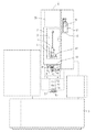
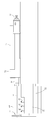
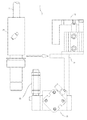
図1に、本発明の細穴放電加工装置の実施の形態の概容が示されている。図1は、細穴放電加工装置を正面から見た平面図であり、基台であるベッドとベッド上のテーブルおよびサドルは省略されている。また、図2に、図1で示される細穴放電加工装置の自動電極供給装置が示されている。図2は、自動電極供給装置と電極案内装置を部分的に抽出して側面から見た平面図である。以下、図1および図2を用いて、本発明の細穴放電加工装置の概容を説明する。
【0017】
加工ヘッド2は、加工穴の深さ方向である鉛直方向のZ軸方向に図示しないリニアモータなどの駆動装置によって往復移動するスライダ21と、Z軸に平行なW軸方向に図示しない回転型のサーボモータによって往復移動するスライダ22を搭載している。
また、加工槽3は、ベッド上に積載される図示しない被加工物を搭載するテーブルおよびサドルによってZ軸方向と垂直な平面方向で互いに直交するX軸方向およびY軸方向に往復移動する。パイプ電極1は、スピンドルモータ6で回転させられる。
【0018】
電極ホルダ4は、自動電極供給装置7から送り出されるパイプ電極1を回転可能に保持する。電極ホルダ4は、パイプ電極を保持するコレットホルダ41と図示しない加工液の漏出を防止するシール部材と、コレットホルダ41のパイプ電極の把持と解放を操作するロックナット42とを含んでなる。ロックナット42は、スピンドルモータ6を切り換えて所要の方向に回動され、コレットホルダ41を緩めたり締め付けたりして、パイプ電極1の把持と解放を行なう。通電ブラシ43は、加工中、回転するパイプ電極1に図示しない電源装置からの電流を給電線を通して供給する。
【0019】
コレットフィンガ44はロックナット42を把持するものであり、コレットフィンガ44がロックナット42を把持している間にスピンドルモータ6を回転させるとコレットホルダ41のみが回転することによってロックナット42がコレットホルダ41を緩めたり締め付けたりする。クランプ機構45は、電極ホルダ4を加工ヘッド2から取り外すための装置である。消耗して使用できなくなったパイプ電極1は、図示しない旋回アームによってを回収バケットまで搬送される。電極ホルダ4のより詳細な構成は、特許文献5に開示されている技術が参照される。
【0020】
ガイド装置5は、スライダ22の下端に固定された支持体55に設けられた下側ガイド装置51と複数の中間ガイド52,53,54を含んで成る。下側ガイド装置51は、パイプ電極1を把持解放することができる図示しないガイドフィンガを含む。中間ガイド52ないし54は、パイプ電極1の撓みを防止するために、下側ガイド51と電極ホルダ4との間でパイプ電極1を支持案内するものであり、下側ガイド51と電極ホルダ4との距離に応じてパイプ電極1の方向に突出させて使用され、不要なときは、図2に示されているように、支持体55側に収納される。なお、図示しない加工液タンクから供給される加工液は、加工液導入口60から導入されパイプ電極1の中空孔を通して加工間隙に噴出される。
【0021】
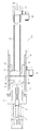
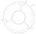
図3は、自動電極供給装置の実施の形態の構成を示す断面図であり、図4は、図3のA−A断面図である。また、図5は、ケースプッシャおよびシールプッシャの外観を示す側面図である。以下、図3ないし図5を用いて、本発明の自動電極供給装置の本体の構成をより詳細に説明する。なお、自動電極供給装置7は、図1に示されるように、スライダ21の中空室23に設けられ、ガイド装置5に対して加工穴の深さ方向に相対的に移動することができる。図1は、スライダ21に設けられた前面カバーが開かれた状態が示されているが、通常は、前面カバーが閉じられた状態で使用される。
【0022】
自動電極供給装置7は、複数本のパイプ電極をまとめて収納するストッカ71と、ストッカ71の下端の開口と連通するホルダブロック10と、ストッカ71の上端に設けられストッカ71の上端の開口を封止するキャップ72と、自動電極供給装置を作動させるケースプッシャ16と、を含んで成る。さらに、ホルダブロック10は、ストッカ71を保持するストッカホルダ11と、パイプ電極1を送り出す送給経路を開放するノッチ12、ノッチ12を押し出すプッシャ13と、プッシャ13を押し戻すコイルばね14と、プッシャ13と一緒に移動し電極の先端を保護するクッションパッド15と、ホルダブロック10をケースプッシャ16が設けられている取付部19に取り付けるナット17を含んで成る。
【0023】
自動電極供給装置7のホルダブロック10は、スライダ21の中空室23内に固定されているケースプッシャ16およびシールプッシャ61の位置に合致するように、図5の白抜きの矢印で示される方向から取付部19にセットしてナット18を締め付けることによって取り付けられる。シールプッシャ61は、加工液導入口60から加工液噴流が供給されているときは閉じられており、加工液がストッカ71側へ噴出しないようにしている。
【0024】
ストッカホルダ11は、実施の形態では、内径がほぼφ10mmの挿入孔を有しており、外径がφ10mmの高剛性の専用のストッカ(電極ケース)を装着することができる。ホルダブロック10は、乾燥した空気の第1導入口73を有しており、第1導入口73には乾燥装置に接続するフレキシブルチューブが接続されている。第1導入口73からの圧縮空気は、空気溜74から複数の噴出孔18を通ってクッションパッド15側の乾燥室75に噴出される。
【0025】
複数の噴出孔18は、図4に示されるように偏心して設けられている。このため、複数の噴出孔18は、空気の渦流を乾燥室75内に発生させる。乾燥した空気の渦流は、乾燥室75、クッションパッド15の内壁面、およびストッカ71の壁面を万遍なく乾燥させるだけでなく、パイプ電極1の先端は互いに散り散りにされて乾燥され、パイプ電極1どうしの付着とパイプ電極1の壁面への付着が解消され、パイプ電極1が固まり合うことがより確実に防止される。また、好ましくは、噴出孔18の乾燥室75へ連通する角度を50〜70度にすることにより、空気の渦流が効果的に発生し、より確実にパイプ電極1どうしの付着を解消させることが期待される。
【0026】
キャップ72は乾燥した空気の第2導入口76を有しており、キャップ72がストッカ71に嵌め込まれた後に乾燥装置に接続するフレキシブルチューブが接続される。第2導入口76からの乾燥した空気は、ストッカ71内を乾燥させてパイプ電極1どうしがくっ付き合ったり、パイプ電極1がストッカ71の内壁面に付着することをより確実に防止する。また、キャップ72の上部にはガスまたは液体の洗浄剤(脱脂剤)を導入するフレキシブルチューブ84が圧入されており、スプレー缶83の噴射口と接続されている。スプレー缶83から供給される脱脂剤は、ストッカ71内とパイプ電極1に付着している油分を除去して、パイプ電極1が円滑に1本ずつ送り出されることを助ける。
【0027】
プッシャ13は、自動電極供給装置7の本体が取り付けられたケースプッシャ16のエアシリンダによりプッシャ13のフランジ13Aが押し出されることによって、プッシャ13がクッションパッド15とともに、コイルばね14の復元力に抗して下向きに移動する。プッシャ13が作動したときは、ノッチ12も下側に動いてノッチ12の先端の図示しないリングがノッチ12から外れる。上記リングがノッチ12から外れるとノッチ12が解放され、パイプ電極1の外径よりも僅かに大きな内径を有する送給経路を形成する。一方、クッションパッド15とプッシャ13には、パイプ電極1の外径を基準に正確な大きさの直径を有する送給経路が形成されているから、確実に1本のパイプ電極がノッチ12を通って自由落下する。
【0028】
ケースプッシャ16のエアシリンダが逆に動作すると、プッシャ13は、コイルばね14のバネ力によって上側に押し戻される。プッシャ13が上側に押し戻されると、ノッチ12も上側に移動して上記リングがノッチ12の先端に引っ掛かってノッチ12を閉鎖させ、プッシャ13が所定の位置で停止する。
【0029】
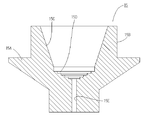
図6に、クッションパッド15の具体的な構成の一例が示されている。クッションパッド15は、ゴムや弾性を有する樹脂によって形成され、プッシャ13と同様に、所定の位置より上側に移動しない。外周円盤15Aから上側に形成されるフランジ15Bは、乾燥室75におけるクッションパッド15とストッカ71の開口との間隔を小さくし、第1導入口73から供給される圧縮空気によって乾燥室75内を跳ねるパイプ電極1の先端が供給経路から外れにくくしている。
【0030】
クッションパッド15の内壁は平滑なテーパ面15Cと段状面15Dが形成されている。段状面15Dは、複数本のパイプ電極1がストッカ71に装填されたときに、パイプ電極1がクッションパッド15の底面の中心部分に集まりにくくするものであり、パイプ電極1の先端が集合することでパイプ電極1の自由落下が妨げられることを防止する。
【0031】
このように、パイプ電極1は、第1導入口73と第2導入口76から供給される乾燥した圧縮空気によって水分が除去されるとともに、乾燥室75に発生する空気の渦流によってクッションパッド15の内側で先端部が散り散りにされ、平滑なテーパ面15Cに沿って段状面15で底面の1箇所に集まらないようにされながら、送給経路15Eに1本毎に確実に送り出される。したがって、この実施の形態のクッションパッドは、パイプ電極が供給経路から外れにくくして確実に1本毎に送り出される点で、特に優れた構成を有しており、本発明の効果をより確実なものにしている。
【0032】
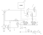
図7に、本発明の細穴放電加工装置の洗浄装置と乾燥装置のシステムが示されている。洗浄装置8と乾燥装置9を作動させる加圧された圧縮空気の供給源は共通であり、制御装置100によって予め規定されたプログラムまたは作業者のスイッチ操作により制御弁である電磁切換弁85または電磁切換弁91を操作して、脱脂剤または静電気防止剤および乾燥された圧縮空気をパイプ電極を供給する工程に合わせて選択的に供給する。なお、逆止弁、絞り弁、スピードコントローラなどの回路中に適宜設計的に設けられる部材については説明を省略する。
【0033】
洗浄装置8は、コンプレッサ31、フィルタ32、エアレギュレータ33、ドライヤ34、ブラケット81、留具82、スプレー缶83、フレキシブルチューブ84、電磁切換弁85、エアシリンダ86を含んで成る。なお、ブラケット81、留具82、スプレー缶83が設けられている位置は、図1に示されている。
【0034】
洗浄装置8は、交換可能な市販のスプレー缶83の脱脂剤をストッカ71内に噴射させて、ストッカ71の内側またはパイプ電極1に付着している油分を除去する。したがって、パイプ電極が油分によって、ストッカ71やホルダブロック10の内壁に付着したり、パイプ電極どうしがくっついて、パイプ電極が送り出せなくなることをより確実に防止することができる。好ましくは、パイプ電極を供給する工程に合わせて脱脂剤と静電気防止剤とを自動的に交換させながら使用できるように構成するのがよいが、静電気防止剤は頻繁に使用する必要がないので、実施の形態では、脱脂剤のみを噴霧するようにしている。
【0035】
コンプレッサ31は、エアシリンダ86を作動させるための圧縮空気の供給源である。コンプレッサ31からの圧縮空気はフィルタ32を通してエアレギュレータ33で所定の圧力になるように減圧される。ドライヤ34には乾燥剤を充填した乾燥器が並設されており、減圧された圧縮空気は乾燥器の乾燥剤とドライヤ34の温風とによって水分が取り除かれてから電磁切換弁85に至る。
【0036】
制御装置100からの信号で電磁切換弁85が切り換えられると、エアシリンダ86が下向きに作動して、装着されているスプレー缶83のノズルを押し、スプレー缶83から脱脂剤を噴射させる。噴射された脱脂剤は、フレキシブルチューブ84を通ってキャップ72からストッカ71に噴出される。所定の時間後、制御装置100からの信号で電磁切換弁85が元の位置に切り換えられると、エアシリンダ86が上向きに作動して、スプレー缶83のノズルの押圧を解除する。したがって、制御装置100によって自動的に脱脂剤が供給停止されるから、作業者の負担がない。また、市販のスプレー缶を装着する構成であるから、利便性に優れる。
【0037】
乾燥装置9は、コンプレッサ31、フィルタ32、エアレギュレータ33、ドライヤ34、ドライヤ34の入口側に設けられ乾燥剤が充填された図示しない乾燥器、電磁切換弁91を含んで成る。乾燥装置8は、既に洗浄装置8によって脱脂されている複数のパイプ電極とストッカ71内壁に乾燥した圧縮空気を吹き付けて水分を取り除く。したがって、パイプ電極から水分が取り除かれ乾燥させた状態にするから、パイプ電極どうしが水分によって互いにくっつき合うことをより確実に防止する。
【0038】
乾燥装置9のコンプレッサ31から電磁切換弁85までの部材は洗浄装置8と共有している。制御装置100からの信号で電磁切換弁91が切り換えられると、乾燥した圧縮空気が第1導入口73から自動供給装置7のホルダブロック10内に供給され、パイプ電極から水分が除去される。したがって、制御装置100によって自動的に乾燥した圧縮空気が供給停止されるから、作業者の負担がない。また、図示しない制御弁が第2導入口76への回路を開いているときには、第2導入口76からも乾燥した圧縮空気がストッカ71内に供給され、ストッカ71内が乾燥状態にされ、一層確実にパイプ電極1どうしがくっ付き合ったり、パイプ電極1がストッカ71の内壁面に付着することを防止する。
【0039】
次に、本発明の実施の形態における作業工程および装置の動作を説明する。まず、脱脂剤のスプレー缶83を洗浄装置8にセットする作業について説明する。作業者は、スプレー缶83の頭部の噴出部分にプラスチック製のノズルを装着する。そして、スプレー缶83を留具82でブラケット81上に固定する。このとき、エアシリンダ86との間にスペースがありすぎる場合は、所定の形状のスペーサを装着し、エアシリンダ86が下向きに作動したときに確実にスプレー缶83の頭部のピンが押されて脱脂剤が噴射するようにしておく。
【0040】
次に、パイプ電極を自動電極供給装置にセットする作業について説明する。作業者は、前面カバーを明けてキャップ72を取り外してスットカ71に複数の同径のパイプ電極1を静かに投入するか、またはキャップ72を取り外してから自動電極供給装置7の本体を取り外してストッカ71に複数の同径のパイプ電極を入れる。パイプ電極1をストッカ71に入れたら、キャップ72でスットカ11の上端の開口を封鎖する。なお、自動電極供給装置7の本体は、取付部19の所定の位置に嵌め込んで、ナット16を締めてホルダブロック10を固定することによって、細穴放電加工装置の本機に取り付けられる。
【0041】
放電加工に使用することができなくなったパイプ電極を排出するときは、制御装置100は、まず、スライダ21およびスライダ22を所定の位置まで移動させ、図示しない旋回アームを移動させて旋回アーム先端のフィンガによりパイプ電極を保持する。次に、コレットフィンガ44によってコレットナット42を把持し、スピンドルモータ6を所定時間回転させてコレットナット42を緩めてからスライダ21を上昇させ、パイプ電極を電極ホルダ4から引き抜く。そして、旋回アームを元の位置まで移動させ、フィンガを開いて、その直下に移動されている回収バケットに落下させる。
【0042】
図8に、自動電極供給装置を用いてパイプ電極を自動的に供給するときの制御装置の基本的な動作が示されている。次に、図8を用いて新しいパイプ電極を自動的に供給する動作を説明する。なお、装置については、図1ないし図7が参照される。
【0043】
まず、制御装置100は、図示しない加工液供給装置を停止させ、加工液導入口60からの加工液噴流の供給を中断する。そして、電磁切換弁85を切り換えてエアシリンダ86を下方向に作動させ、スプレー缶83のノズルを押圧し、ストッカ71内に脱脂剤を噴射する。所定時間後に、制御装置100は電磁切換弁85を元の位置に切り換えてエアシリンダ86を上方向に作動させてスプレー缶83の押圧を解除する(S1)。
【0044】
次に、制御装置100は、電磁切換弁91を切り換えて、第1導入口73および第2導入口76から乾燥した圧縮空気を室内に噴出する。このとき、乾燥室75のクッションパッド15の中には、ストッカ71からのパイプ電極1の先端が位置しており、パイプ電極1は、乾燥した圧縮空気により水分が除去されると同時に付着し合っているパイプ電極1が散り散りに引き離される(S2)。
【0045】
次に、下側ガイド装置51のガイドフィンガを開くとともにコレットフィンガ44によってロックナット42を把持し、スピンドルモータ6を所定回転数だけ回転させてコレットホルダ41を所定の方向に回動させ、ロックナット42を緩めて、コレットホルダ41を解放する(S3)。そして、スライダ21を所定の第1の位置まで移動させる。この第1の位置は、パイプ電極が自由落下によって下側に落とされるときに、より確実に下側ガイド装置51の案内部分に入る高さであり、スライダ21が第1の位置にあるときは、電極ホルダ4と下側ガイド装置51の間隔が狭められている(S4)。
【0046】
スライダ21が第1の位置まで移動したら、加工液噴流がホルダブロック10側に流入しないようにしているシールプッシャ61を開放して、パイプ電極1が自然に落下できる供給経路をつくる(S5)。そして、ケースプッシャ16を作動させて、ケースプッシャ16のエアシリンダによりプッシャ13を下向きに移動させる。プッシャ13が下向きに移動するとノッチ12も移動し、ノッチ12の先端のリングが外れてノッチ12が解放される(S6)。このとき、乾燥した圧縮空気によりパイプ電極1は互いにくっつかないようになっており、クッションパッド15の作用で確実に1本のパイプ電極1が自由落下するので、パイプ電極が詰まってパイプ電極の供給動作が中断することがない。
【0047】
パイプ電極は、設置してある被加工物の上面まで落下し被加工物とパイプ電極1とが接触すると、電気的に両者を接触感知することにより、パイプ電極が所定の位置まで送り出されたことが確認される。パイプ電極が所定の位置まで送り出されたら、下側ガイド装置51のコレットフィンガを閉じてパイプ電極を把持する(S7)。そして、スライダ21を所定の第2の位置まで上昇させる(S8)。この第2の位置は、ノッチ12が閉じたときにパイプ電極がノッチ12に挟まれることがない位置である。
【0048】
次に、ケースプッシャ16のエアシリンダを逆向きに作動させ、コイルばね14の復元力によってノッチ12、プッシャ13、およびクッションパッド15を元の位置に戻す(S9)。さらに、スライダ21を所定の第3の位置まで上昇させて(S10)、シールプッシャ61を閉じ、加工液噴流が自動電極供給装置の方に吹き上げないようにする(S11)。第3の位置は、シールプッシャ61を閉じたときにパイプ電極の上端がシールプッシャ61によって挟まれない位置である。
【0049】
次に、スライダ21を所定の第4の位置まで上昇させてから(S12)、スピンドルモータ6を逆方向に所定のトルクに到達するまで駆動させてロックナット42を締め付けて、コレットホルダ41を閉じ、新しいパイプ電極を電極ホルダ4に保持させる(S13)。第4の位置は、パイプ電極の長さに応じて変更設定される。最後に、下側ガイド装置51のガイドフィンガを開いて終了する(S14)。
【0050】
本発明は、上述した実施の形態に限定されるものではなく、本発明の技術思想を逸脱しない範囲で、異なる実施の形態を採用することができる。例えば、洗浄装置は、スプレー缶をエアシリンダで押圧して噴射させるものではなく、特定の噴射装置を設けてその特定の噴射装置を電気的に作動させるようにしてもよい。また、乾燥装置は、乾燥した圧縮空気を送るようにするものではなく、静電気防止剤を含んだ乾燥ガスを供給するようにすることができる。その他、ガイド装置、加工液供給装置、電極把持装置などの装置は、従来の公知の種々の構成を採用することができ、また、開示された実施の形態を変形、組合せ、置換、材料の変更などによって種々の構成を採用することが可能である。例えば、洗浄装置や乾燥装置の回路における電磁切換弁は、シリンダなど同種の作用を有する部材に置き換えることができる。
【0051】
【発明の効果】
本発明の細穴放電加工装置によれば、φ0.5mm以下の長尺のパイプ電極を自動的に供給するときに、パイプ電極どうしがくっつくなどしてパイプ電極を供給することができなくなることをより確実に防止することができる。また、制御装置の動作によってパイプ電極の洗浄と乾燥を行なうことができるから、作業者の手を煩わせることがない。その結果、多数の細孔を長時間連続加工するときなど、作業の効率が大幅に向上するという効果を奏する。
【図面の簡単な説明】
【図1】本発明の細穴放電加工装置の実施の形態の正面図である。
【図2】本発明の細穴放電加工装置の実施の形態の要部を示す右側面図である。
【図3】自動電極供給装置の本体を示す断面図である。
【図4】図3で示された自動電極供給装置のA−A断面図である。
【図5】ケースプッシャおよびシールプッシャの外観を示す右側面図である。
【図6】クッションパッドの構成を示す断面図である。
【図7】本発明の洗浄装置および乾燥装置の構成を示すブロック図である。
【図8】本発明の自動電極供給装置を制御する制御装置の動作を示すフローチャートである。
【符号の説明】
7 自動電極供給装置
71 ストッカ
72 キャップ
73 第1導入口
75 乾燥室
76 第2導入口
11 ストッカホルダ
12 ノッチ
13 プッシャ
14 コイルばね
15 クッションパッド
16 ケースプッシャ
17 ナット
18 噴出孔[0001]
[Industrial application fields]
The present invention relates to an electric discharge machining apparatus, particularly a small hole electric discharge machining apparatus for drilling a hole having a diameter of 0.5 mm or less, and a thin hole electric discharge machining apparatus provided with an automatic electrode supply device capable of more reliably replacing and supplying a tool electrode. About.
[0002]
[Prior art]
The tool electrode and the workpiece are arranged opposite to each other with a predetermined gap, and a discharge voltage is applied to the machining gap formed by the tool electrode and the workpiece to generate a discharge in the machining gap. 2. Description of the Related Art There is known an electric discharge machining apparatus in which a workpiece is processed in a desired shape by moving relative to the workpiece. In general, the electric discharge machining apparatus is roughly classified into a sculpting electric discharge machining apparatus and a wire cut electric discharge machining apparatus from the form of machining and the overall configuration of the apparatus. Further, among the sculpture electric discharge machining apparatuses, there is a small hole electric discharge machining apparatus as a device for machining fine holes and pores having a diameter of several mm or less.
[0003]
In the small hole electric discharge machining, a machining hole or a through hole whose depth is several to several hundreds times as large as the hole diameter is machined. It will be very long. In electric discharge machining, the tool electrode is consumed to some extent due to its characteristics, but most of the small hole electric discharge machining is aimed at continuously penetrating pores with a diameter of several mm or less. The machining speed is more important than the wear characteristics of the tool electrode compared to the sculpting electric discharge machining for the purpose of machining. For this reason, in the small hole electric discharge machining, since a discharge current having a considerably higher current density is supplied compared to the sculpting electric discharge machining, the tool electrode is consumed violently.
[0004]
Therefore, the tool electrode for processing the pores needs to be considerably longer than the desired depth of the through hole. For this reason, as shown in Patent Document 2, a linear tool electrode wound around a bobbin was often used as a tool electrode for fine hole electric discharge machining. When the depth of the machining hole is several tens to several hundred times, the method of supplying the machining fluid jet in general sculpture electric discharge machining cannot be adopted, and it is difficult to discharge the machining waste from the machining hole. In this state, electrical discharge machining itself is impossible, and in order to solve this problem, it is desirable to supply a machining fluid jet from the tool electrode. Therefore, recently, the manufacturing technology of the tool electrode has been improved, and as shown in
[0005]
Tool electrodes for machining pores are made of metal materials with good conductivity and a certain degree of rigidity, such as copper tungsten and silver tungsten, but tool electrodes for machining elongated pores originally have rigidity. Since it lacks, it will be bent or bent and lose its linearity. As shown in
[0006]
As described above, since the tool electrode is consumed violently in the fine hole electric discharge machining, it is necessary to feed out the tool electrode as the machining progresses. In the case of a linear tool electrode wound around a bobbin, it is possible to discharge-process a considerable number of pores continuously by successively feeding the bobbin while correcting the tool electrode. However, in the case of a pipe electrode having a predetermined length, the length of the tool electrode that can be fed out is limited. Therefore, when continuously performing electrical discharge machining of pores using a pipe electrode, as shown in
[0007]
In addition, the tool electrode whose outer diameter is less than φ0.1mm is as thin as the whole hair, so the tool electrode is attached to the electrode holder and set in the magazine, and the tool electrode is replaced with the electrode holder. Have been to. An apparatus for automatically exchanging pipe electrodes in this manner is generally called an automatic electrode changer (ATC, Auto Tool Changer). There is known a small-hole electric discharge machine equipped with both an automatic electrode supply device and an automatic electrode changer, and it seems that it is properly used depending on the size of the pipe electrode. It is not possible to strictly distinguish the method of exchanging them.
[0008]
[Patent Document 1]
JP-A-5-177450 (
[Patent Document 2]
Japanese Utility Model Publication No. 32-4995
[Patent Document 3]
JP 56-69033 A (
[Patent Document 4]
Japanese Utility Model Publication No. 3-11526
[Patent Document 5]
JP 2000-301417 A (pages 6 to 7)
[0009]
[Problems to be solved by the invention]
By the way, pipe electrodes with a diameter of 0.5 mm or less are very long and weak in rigidity, so pipe electrodes that are about to be fed out due to oil and fat, moisture, or static electricity, or pipe electrodes are members in the supply path. Stick to the wall. As a result, in a small hole electrical discharge machining apparatus equipped with an automatic electrode supply device, it is often the case that a new pipe electrode cannot be supplied due to multiple pipe electrodes being sent out simultaneously or being caught. Yes. Therefore, although depending on the type of automatic electrode supply device, the success rate when supplying the pipe electrode is about 10% when it is terrible, greatly hindering continuous processing for a long time.
[0010]
An object of the present invention is to provide a fine hole electric discharge machining apparatus provided with an automatic electrode supply apparatus that can reduce clogging of pipe electrodes in the automatic electrode supply apparatus and improve work efficiency. In addition, some specific and detailed advantages in the embodiment of the fine hole electric discharge machining apparatus of the present invention will be clarified as appropriate in the description of the embodiment of the present invention.
[0011]
[Means for Solving the Problems]
The thin hole electric discharge machining apparatus of the present invention includes a stocker (71) for storing a plurality of pipe electrodes (1) having a diameter of 0.5 mm or less, and an automatic electrode for sending pipe electrodes (1) from the stocker (71) one by one. The fine hole electric discharge machining apparatus provided with the supply device (7) includes a cleaning device (8) provided in communication with the upper opening of the stocker (71) and supplying a cleaning agent into the stocker (71).
[0012]
Preferably, the cleaning device (8) includes a compressed air supply source (31), an electromagnetic switching valve (85) for switching supply of compressed air from the supply source (31), and compressed air from the supply source (31). It comprises an air cylinder (86) that operates and supplies a cleaning agent to the stocker (71), and a control device (100) that operates the electromagnetic switching valve (85).
[0013]
Moreover, the fine hole electric discharge machining apparatus of the present invention includes a stocker (71) for storing a plurality of pipe electrodes (1) having a diameter of 0.5 mm or less, and sends out the pipe electrodes (1) from the stocker (71) one by one. In a fine hole electric discharge machining apparatus equipped with an automatic electrode supply device (7), a pipe is formed by supplying dry compressed air from a first inlet (73) provided in a holder block (10) holding a stocker (71). It comprises a drying device (9) for drying the electrode (1).
[0014]
Preferably, the compressed air dried from the cap (72) attached to the upper end of the stocker (71) and sealing the opening at the upper end of the stocker (71) and the second inlet (76) provided in the cap (72). And a drying device (9) for drying the pipe electrode (1). Preferably, the drying device (9) includes a compressed air supply source (31), a dryer for drying the compressed air, an electromagnetic switching valve (91) for switching the supply of compressed air, and an electromagnetic switching valve (91 And a control device (100) for operating. More preferably, the drying chamber (75) that is formed in the holder block (10) and communicates with the first introduction port (73), and the first introduction port (73) and the drying chamber (75) communicate with each other. It comprises a plurality of communicating holes (18) provided in the center.
[0015]
Preferably, the pipe electrode (1) is provided in the drying chamber (75) and moves in the direction in which the pipe electrode (1) is fed when the pipe electrode (1) is fed, and the tip of the pipe electrode (1) is fed to the feeding path. A cushion pad (15) leading to (15E). More preferably, the cushion pad (15) has a flange (15B) formed on the outside and a tapered surface (15C) and a stepped surface (15D) formed on the inside. For convenience, each means is specifically described along the embodiment with reference numerals, but it does not mean that the narrow hole electric discharge machining apparatus of the present invention is limited to the embodiment.
[0016]
DETAILED DESCRIPTION OF THE INVENTION
FIG. 1 shows an outline of an embodiment of a thin hole electric discharge machining apparatus of the present invention. FIG. 1 is a plan view of a thin hole electric discharge machining apparatus as viewed from the front, and a bed as a base, a table on the bed, and a saddle are omitted. Further, FIG. 2 shows an automatic electrode supply device of the fine hole electric discharge machining apparatus shown in FIG. FIG. 2 is a plan view of the automatic electrode supply device and the electrode guide device partially extracted and viewed from the side. Hereinafter, an outline of the thin hole electric discharge machining apparatus of the present invention will be described with reference to FIGS. 1 and 2.
[0017]
The machining head 2 includes a
Further, the
[0018]
The
[0019]
The collet finger 44 grips the lock nut 42. When the spindle motor 6 is rotated while the collet finger 44 grips the lock nut 42, only the collet holder 41 rotates, so that the lock nut 42 is collet holder. Loosen or tighten 41. The clamp mechanism 45 is a device for removing the
[0020]
The
[0021]
FIG. 3 is a cross-sectional view showing the configuration of the embodiment of the automatic electrode supply apparatus, and FIG. 4 is a cross-sectional view taken along the line AA of FIG. FIG. 5 is a side view showing the appearance of the case pusher and the seal pusher. Hereinafter, the configuration of the main body of the automatic electrode supply device of the present invention will be described in more detail with reference to FIGS. As shown in FIG. 1, the automatic
[0022]
The automatic
[0023]
The
[0024]
In the embodiment, the stocker holder 11 has an insertion hole having an inner diameter of approximately φ10 mm, and a high-rigidity dedicated stocker (electrode case) having an outer diameter of φ10 mm can be mounted. The
[0025]
The plurality of ejection holes 18 are provided eccentrically as shown in FIG. For this reason, the plurality of ejection holes 18 generate an air vortex in the drying
[0026]
The
[0027]
The
[0028]
When the air cylinder of the case pusher 16 operates in reverse, the
[0029]
FIG. 6 shows an example of a specific configuration of the
[0030]
The inner wall of the
[0031]
As described above, the
[0032]
FIG. 7 shows a system of a cleaning device and a drying device of the small hole electric discharge machining apparatus of the present invention. The supply source of pressurized compressed air for operating the cleaning device 8 and the
[0033]
The cleaning device 8 includes a compressor 31, a filter 32, an air regulator 33, a dryer 34, a bracket 81, a fastener 82, a spray can 83, a
[0034]
The cleaning device 8 sprays a degreasing agent of a replaceable commercially available spray can 83 into the
[0035]
The compressor 31 is a supply source of compressed air for operating the air cylinder 86. The compressed air from the compressor 31 is decompressed to a predetermined pressure by the air regulator 33 through the filter 32. The dryer 34 is provided with a dryer filled with a desiccant, and the compressed air that has been decompressed reaches the electromagnetic switching valve 85 after moisture is removed by the desiccant of the dryer and the warm air of the dryer 34.
[0036]
When the electromagnetic switching valve 85 is switched by a signal from the control device 100, the air cylinder 86 operates downward, pushes the nozzle of the spray can 83 attached, and sprays the degreasing agent from the spray can 83. The sprayed degreasing agent is jetted from the
[0037]
The
[0038]
The members from the compressor 31 to the electromagnetic switching valve 85 of the
[0039]
Next, the working process and the operation of the apparatus in the embodiment of the present invention will be described. First, an operation of setting the degreasing agent spray can 83 in the cleaning device 8 will be described. The operator attaches a plastic nozzle to the ejection portion of the spray can 83. Then, the spray can 83 is fixed on the bracket 81 with the fastener 82. At this time, if there is too much space between the air cylinder 86, a spacer having a predetermined shape is attached, and the pin on the head of the spray can 83 is surely pushed when the air cylinder 86 operates downward. Make sure the degreasing agent sprays.
[0040]
Next, an operation for setting the pipe electrode in the automatic electrode supply device will be described. The operator opens the front cover and removes the
[0041]
When discharging the pipe electrode that can no longer be used for electric discharge machining, the control device 100 first moves the
[0042]
FIG. 8 shows the basic operation of the control device when the pipe electrode is automatically supplied using the automatic electrode supply device. Next, the operation of automatically supplying a new pipe electrode will be described with reference to FIG. For the apparatus, reference is made to FIGS.
[0043]
First, the control device 100 stops a machining fluid supply device (not shown) and interrupts the supply of the machining fluid jet from the machining fluid inlet 60. Then, the electromagnetic switching valve 85 is switched to operate the air cylinder 86 in the downward direction, the nozzle of the spray can 83 is pressed, and the degreasing agent is injected into the
[0044]
Next, the control device 100 switches the electromagnetic switching valve 91 to jet dry compressed air from the
[0045]
Next, the guide finger of the
[0046]
When the
[0047]
When the pipe electrode falls to the upper surface of the workpiece to be installed and the workpiece and the
[0048]
Next, the air cylinder of the case pusher 16 is operated in the opposite direction, and the
[0049]
Next, after raising the
[0050]
The present invention is not limited to the above-described embodiments, and different embodiments can be adopted without departing from the technical idea of the present invention. For example, the cleaning device does not press the spray can with an air cylinder and injects the spray can, but may provide a specific injection device to electrically operate the specific injection device. Also, the drying device does not send dry compressed air, but can supply a dry gas containing an antistatic agent. Other devices such as a guide device, a machining fluid supply device, and an electrode gripping device can adopt various conventional known configurations, and can change, combine, replace, and change materials of the disclosed embodiments. Various configurations can be adopted depending on the above. For example, the electromagnetic switching valve in the circuit of the cleaning device or the drying device can be replaced with a member having the same kind of action as a cylinder.
[0051]
【The invention's effect】
According to the thin hole electric discharge machining apparatus of the present invention, when a pipe electrode having a length of φ0.5 mm or less is automatically supplied, the pipe electrodes cannot be supplied due to sticking between them. It can prevent more reliably. Further, since the pipe electrode can be cleaned and dried by the operation of the control device, the operator's hand is not bothered. As a result, there is an effect that the work efficiency is greatly improved, for example, when a large number of pores are continuously processed for a long time.
[Brief description of the drawings]
FIG. 1 is a front view of an embodiment of a narrow hole electric discharge machining apparatus of the present invention.
FIG. 2 is a right side view showing the main part of the embodiment of the narrow hole electric discharge machining apparatus of the present invention.
FIG. 3 is a cross-sectional view showing a main body of the automatic electrode supply device.
4 is a cross-sectional view taken along line AA of the automatic electrode supply device shown in FIG.
FIG. 5 is a right side view showing the appearance of a case pusher and a seal pusher.
FIG. 6 is a cross-sectional view showing a configuration of a cushion pad.
FIG. 7 is a block diagram showing a configuration of a cleaning device and a drying device of the present invention.
FIG. 8 is a flowchart showing the operation of a control device for controlling the automatic electrode supply device of the present invention.
[Explanation of symbols]
7 Automatic electrode feeder
71 Stocker
72 cap
73 First inlet
75 Drying room
76 Second inlet
11 Stocker holder
12 notches
13 Pusher
14 Coil spring
15 Cushion pad
16 Case pusher
17 Nut
18 Ejection hole
Claims (8)
前記ストッカの上側開口と連通して設けられ前記ストッカ内に洗浄剤を供給する洗浄装置を含んでなる細穴放電加工装置。In a small hole electric discharge machining apparatus including an automatic electrode supply device that includes a stocker that stores a plurality of pipe electrodes having a diameter of 0.5 mm or less and that feeds the pipe electrodes from the stocker one by one.
A fine hole electric discharge machining apparatus including a cleaning device provided in communication with an upper opening of the stocker and supplying a cleaning agent into the stocker.
を含んでなる請求項1に記載の細穴放電加工装置。The cleaning device includes a supply source of compressed air, a control valve that switches supply of the compressed air, an air cylinder that is operated by the compressed air and supplies a cleaning agent to the stocker, and a control device that operates the control valve. It becomes.
The fine hole electric discharge machining apparatus according to claim 1, comprising:
前記ストッカを保持するホルダブロックに設けられた第1導入口から乾燥した圧縮空気を供給して前記パイプ電極を乾燥させる乾燥装置を含んでなる細穴放電加工装置。In a small hole electric discharge machining apparatus including an automatic electrode supply device that includes a stocker that stores a plurality of pipe electrodes having a diameter of 0.5 mm or less and that feeds the pipe electrodes from the stocker one by one.
A fine hole electric discharge machining apparatus comprising a drying device for drying the pipe electrode by supplying dry compressed air from a first inlet provided in a holder block for holding the stocker.
Priority Applications (1)
| Application Number | Priority Date | Filing Date | Title |
|---|---|---|---|
| JP2002304875A JP4027770B2 (en) | 2002-10-18 | 2002-10-18 | Small hole electric discharge machine |
Applications Claiming Priority (1)
| Application Number | Priority Date | Filing Date | Title |
|---|---|---|---|
| JP2002304875A JP4027770B2 (en) | 2002-10-18 | 2002-10-18 | Small hole electric discharge machine |
Publications (2)
| Publication Number | Publication Date |
|---|---|
| JP2004136413A JP2004136413A (en) | 2004-05-13 |
| JP4027770B2 true JP4027770B2 (en) | 2007-12-26 |
Family
ID=32452172
Family Applications (1)
| Application Number | Title | Priority Date | Filing Date |
|---|---|---|---|
| JP2002304875A Expired - Lifetime JP4027770B2 (en) | 2002-10-18 | 2002-10-18 | Small hole electric discharge machine |
Country Status (1)
| Country | Link |
|---|---|
| JP (1) | JP4027770B2 (en) |
Cited By (2)
| Publication number | Priority date | Publication date | Assignee | Title |
|---|---|---|---|---|
| CN109014455A (en) * | 2018-06-22 | 2018-12-18 | 株式会社沙迪克 | Electric discharge device |
| US12337403B2 (en) | 2020-10-09 | 2025-06-24 | Sodick Co., Ltd. | Change device, fine hole electric discharge machine and electrode change method |
Families Citing this family (3)
| Publication number | Priority date | Publication date | Assignee | Title |
|---|---|---|---|---|
| CN101745706B (en) * | 2008-12-09 | 2011-07-20 | 财团法人金属工业研究发展中心 | Disc cover for electrical discharge machining and guide eye mold device with disc cover for electrical discharge machining |
| US9776267B1 (en) * | 2016-06-14 | 2017-10-03 | Johnson Technology, Inc. | Electrical discharge machining electrode holder |
| CN106270862B (en) * | 2016-10-19 | 2018-03-16 | 大连大学 | A kind of electrode clamping device |
-
2002
- 2002-10-18 JP JP2002304875A patent/JP4027770B2/en not_active Expired - Lifetime
Cited By (3)
| Publication number | Priority date | Publication date | Assignee | Title |
|---|---|---|---|---|
| CN109014455A (en) * | 2018-06-22 | 2018-12-18 | 株式会社沙迪克 | Electric discharge device |
| US11203075B2 (en) | 2018-06-22 | 2021-12-21 | Sodick Co., Ltd. | Electric discharge machining apparatus |
| US12337403B2 (en) | 2020-10-09 | 2025-06-24 | Sodick Co., Ltd. | Change device, fine hole electric discharge machine and electrode change method |
Also Published As
| Publication number | Publication date |
|---|---|
| JP2004136413A (en) | 2004-05-13 |
Similar Documents
| Publication | Publication Date | Title |
|---|---|---|
| EP3160680B1 (en) | Welding torch maintenance apparatus for servicing a torch, and a welding tip changing apparatus | |
| JP2003532793A5 (en) | Apparatus and method for directing fluid on the side of a microelectronic workpiece | |
| JP3097793B2 (en) | Wire cutting machine with wire guiding device for electric discharge machine | |
| JPH05169322A (en) | Electric discharge machining device for drilling | |
| JP4027770B2 (en) | Small hole electric discharge machine | |
| CN102131608B (en) | Wire guide housing for wire electrical discharge machining device | |
| EP1729910A4 (en) | Apparatus and method for automated servicing of a welding torch | |
| JP2002301623A (en) | Fine hole electric discharge machine and fine hole electric discharge machining method | |
| CA2523017C (en) | Device for cleaning the gas nozzle of a welding torch | |
| JP2009291912A (en) | Tool holder washing device for machine tool | |
| CN114309847B (en) | Pore electric discharge machine and electrode replacement method | |
| CN101351291B (en) | Wire EDM | |
| JP2006224215A (en) | Wire electric discharge machine | |
| JP7623485B2 (en) | Parts exchange device and parts exchange system | |
| US6642469B2 (en) | Electrode clamping system for sink-type electrical discharge machines | |
| JP2016005861A (en) | Machining system and tool holding device for machining system | |
| JP2005081489A (en) | Method and apparatus for cleaning tool holder fitting portion of spindle device in machine tool | |
| JP2504638Y2 (en) | Wire electric discharge machine | |
| JPH0441129A (en) | Wire electric discharge machine | |
| JP2004142060A (en) | Cleaning device for machine tool equipped with tool changer | |
| JPH11347881A (en) | Work machining device | |
| JP4169405B2 (en) | Machine tool with cutting oil supply device | |
| JP2889898B2 (en) | Upper liquid supply device for wire cut electric discharge machining | |
| JP2004009181A (en) | Circulation feed mechanism for sand blasting abrasive and sand blasting device | |
| EP0460221A1 (en) | Wire piece recovery apparatus |
Legal Events
| Date | Code | Title | Description |
|---|---|---|---|
| A621 | Written request for application examination |
Free format text: JAPANESE INTERMEDIATE CODE: A621 Effective date: 20050801 |
|
| A977 | Report on retrieval |
Free format text: JAPANESE INTERMEDIATE CODE: A971007 Effective date: 20070827 |
|
| TRDD | Decision of grant or rejection written | ||
| A01 | Written decision to grant a patent or to grant a registration (utility model) |
Free format text: JAPANESE INTERMEDIATE CODE: A01 Effective date: 20071009 |
|
| A61 | First payment of annual fees (during grant procedure) |
Free format text: JAPANESE INTERMEDIATE CODE: A61 Effective date: 20071010 |
|
| FPAY | Renewal fee payment (event date is renewal date of database) |
Free format text: PAYMENT UNTIL: 20101019 Year of fee payment: 3 |
|
| R150 | Certificate of patent or registration of utility model |
Ref document number: 4027770 Country of ref document: JP Free format text: JAPANESE INTERMEDIATE CODE: R150 Free format text: JAPANESE INTERMEDIATE CODE: R150 |
|
| FPAY | Renewal fee payment (event date is renewal date of database) |
Free format text: PAYMENT UNTIL: 20101019 Year of fee payment: 3 |
|
| FPAY | Renewal fee payment (event date is renewal date of database) |
Free format text: PAYMENT UNTIL: 20111019 Year of fee payment: 4 |
|
| R250 | Receipt of annual fees |
Free format text: JAPANESE INTERMEDIATE CODE: R250 |
|
| FPAY | Renewal fee payment (event date is renewal date of database) |
Free format text: PAYMENT UNTIL: 20121019 Year of fee payment: 5 |
|
| R250 | Receipt of annual fees |
Free format text: JAPANESE INTERMEDIATE CODE: R250 |
|
| FPAY | Renewal fee payment (event date is renewal date of database) |
Free format text: PAYMENT UNTIL: 20131019 Year of fee payment: 6 |
|
| R250 | Receipt of annual fees |
Free format text: JAPANESE INTERMEDIATE CODE: R250 |
|
| R250 | Receipt of annual fees |
Free format text: JAPANESE INTERMEDIATE CODE: R250 |
|
| R250 | Receipt of annual fees |
Free format text: JAPANESE INTERMEDIATE CODE: R250 |
|
| R250 | Receipt of annual fees |
Free format text: JAPANESE INTERMEDIATE CODE: R250 |
|
| R250 | Receipt of annual fees |
Free format text: JAPANESE INTERMEDIATE CODE: R250 |
|
| R250 | Receipt of annual fees |
Free format text: JAPANESE INTERMEDIATE CODE: R250 |
|
| R250 | Receipt of annual fees |
Free format text: JAPANESE INTERMEDIATE CODE: R250 |
|
| R250 | Receipt of annual fees |
Free format text: JAPANESE INTERMEDIATE CODE: R250 |
|
| R250 | Receipt of annual fees |
Free format text: JAPANESE INTERMEDIATE CODE: R250 |
|
| R250 | Receipt of annual fees |
Free format text: JAPANESE INTERMEDIATE CODE: R250 |
|
| EXPY | Cancellation because of completion of term |