JP4024195B2 - Disk device and control method thereof - Google Patents
Disk device and control method thereof Download PDFInfo
- Publication number
- JP4024195B2 JP4024195B2 JP2003324512A JP2003324512A JP4024195B2 JP 4024195 B2 JP4024195 B2 JP 4024195B2 JP 2003324512 A JP2003324512 A JP 2003324512A JP 2003324512 A JP2003324512 A JP 2003324512A JP 4024195 B2 JP4024195 B2 JP 4024195B2
- Authority
- JP
- Japan
- Prior art keywords
- signal
- voltage
- disturbance
- estimation
- coefficient
- Prior art date
- Legal status (The legal status is an assumption and is not a legal conclusion. Google has not performed a legal analysis and makes no representation as to the accuracy of the status listed.)
- Expired - Fee Related
Links
Images


Description
本発明は、記録/再生ヘッドをアクチュエータにより記録媒体であるディスクの目標トラックへ高精度に位置決めするディスク装置に関する。さらに詳しくは、アクチュエータが受ける外乱のためにヘッドが目標トラックからずれることを抑制するための技術に関する。 The present invention relates to a disk device that positions a recording / reproducing head to a target track of a disk as a recording medium with high accuracy by an actuator. More specifically, the present invention relates to a technique for suppressing the head from deviating from a target track due to a disturbance received by an actuator.
本発明は、また、停止時にヘッドをディスク外のランプブロックなどのヘッド退避部材上にアンロードし、使用時にヘッド退避部材からヘッドをディスク面上にロードさせるロード・アンロード機構を有するディスク装置にかかわり、ヘッド退避部材上での外乱が大きくても適切な速度制御のもとでヘッドをディスク面に安定良くロードさせるための技術に関する。 The present invention also provides a disk device having a load / unload mechanism that unloads the head onto a head retracting member such as a ramp block outside the disk when stopped, and loads the head onto the disk surface from the head retracting member during use. The present invention relates to a technique for stably loading a head onto a disk surface under appropriate speed control even when a disturbance on the head retracting member is large.
近年、磁気ディスク装置などのディスク装置は、小型化、大容量化が急速に進み、トラックの高密度化・狭トラックピッチ化の傾向にあり、目標トラックに対するヘッドの高精度位置決めが重要となっている。あらかじめディスクに記録されたサーボ情報をヘッドが読み取り、目標トラックに対するヘッドの位置誤差信号を生成し、位置誤差信号の大きさを最小にするようにヘッドを位置決め制御する。位置決め速度を高速化するには位置決め制御系の制御周波数を高くすればよい。しかし、ヘッドのアクチュエータの固有機械共振のために、位置決め制御系が不安定になる。このような実情で、制御周波数を高めることには自ずと限界がある。 In recent years, disk devices such as magnetic disk devices have been rapidly reduced in size and capacity, and there has been a trend toward higher track density and narrower track pitch, and high-precision positioning of the head with respect to the target track has become important. Yes. The head reads servo information recorded in advance on the disk, generates a head position error signal with respect to the target track, and controls the head positioning so that the magnitude of the position error signal is minimized. In order to increase the positioning speed, the control frequency of the positioning control system may be increased. However, the positioning control system becomes unstable due to the inherent mechanical resonance of the head actuator. Under such circumstances, there is a limit to increasing the control frequency.
トラックの高密度化・狭トラックピッチ化およびアクチュエータの小型軽量化に伴い、アクチュエータに作用する外乱が位置決め制御系に与える影響は大きくなる。一方、ヘッドの高精度位置決めに対する要求は厳しい。ヘッドの位置決め精度の悪化要因である外乱の低減が重要である。従来、ディスク上のサーボ情報から得たヘッド位置信号とアクチュエータの駆動信号とに基づいて外乱を推定して、フィードフォワード制御により外乱を補償する技術が提案されている(例えば、特許文献1参照。)。
しかし、ディスク上のサーボ情報は一定のサンプリング周期をもつ離散的情報であり、これを再生したヘッド位置信号は連続信号ではない。サーボ情報のサンプリング周波数の制約から、外乱推定手段の制御帯域には上限が存在し、この上限の存在が外乱の正確な推定を困難にする。その結果、ヘッドを目標トラックに対して常に正確に追従させることがむずかしい。 However, the servo information on the disk is discrete information having a constant sampling period, and the head position signal reproduced from this is not a continuous signal. Due to the restriction of the sampling frequency of servo information, there is an upper limit in the control band of the disturbance estimation means, and the presence of this upper limit makes it difficult to accurately estimate the disturbance. As a result, it is difficult to make the head always follow the target track accurately.
本発明は、上記課題を解決するためになされたものであって、外乱推定手段によりアクチュエータ手段に作用する外乱を正確に推定し、外乱を良好に打ち消すことにより、目標トラックに対するヘッドの位置決め精度を向上させることを目的とする。 The present invention has been made to solve the above-described problems, and accurately estimates the disturbance acting on the actuator means by the disturbance estimation means and satisfactorily cancels the disturbance, thereby improving the head positioning accuracy with respect to the target track. The purpose is to improve.
また、ヘッド退避部材上では摺動摩擦による外乱の変動が大きいため、ヘッドスライダ速度は大きく変動する。ヘッドスライダ移動速度のフィードバック制御を施しても、ヘッドローディング速度の変動が大きくスライダがディスクに衝突することがある。 Further, since the fluctuation of the disturbance due to the sliding friction is large on the head retracting member, the head slider speed fluctuates greatly. Even if feedback control of the head slider moving speed is performed, the fluctuation of the head loading speed is large and the slider may collide with the disk.
そこで、本発明は、アクチュエータに作用する摩擦などの外力を補償することにより、ヘッド退避部材上の外乱の変動が大きくても、安定な速度制御が可能なディスク装置を提供することを目的とする。 Accordingly, an object of the present invention is to provide a disk device capable of stable speed control by compensating for an external force such as friction acting on an actuator, even if the fluctuation of the disturbance on the head retracting member is large. .
アクチュエータ手段に加わる軸受摩擦や弾性力、衝撃や振動に起因する慣性力などの外乱を打ち消すために、その外乱の大きさを推定する。外乱の大きさの推定に際して、2つの要素を用いる。1つは、アクチュエータ手段の駆動において発生する電圧を検出し、その検出結果としての電圧信号を用いる。もう1つは、アクチュエータ手段の駆動手段における駆動信号である。ここで、駆動手段における駆動信号としては、駆動手段に入力するものであってもよいし、あるいは、駆動手段から出力するものであってもよい。また、駆動手段における駆動信号に代えて、その駆動信号を生成するもとになる位置制御信号を用いてもよい。すなわち、外乱の大きさを推定するための外乱推定手段を設け、この外乱推定手段をもって、電圧検出手段が検出した電圧信号と駆動手段における駆動信号または位置制御信号とを入力として、外乱推定信号を生成する。2つの要素に基づいて生成した外乱推定信号は、ヘッドに実際に加わる外乱の大きさを正確に推定したものとなる。この結果、アクチュエータ手段の軸受摩擦やアクチュエータ手段と電子回路基板とを接続するFPC(フレキシブルプリント回路)の弾性力やディスク装置に外部から加わる衝撃や振動によりアクチュエータ手段が受ける慣性力などの外乱の大きさを正確に推定することができる。 In order to cancel disturbances such as bearing friction and elastic force applied to the actuator means and inertial forces caused by impact and vibration, the magnitude of the disturbance is estimated. Two factors are used in estimating the magnitude of the disturbance. One is to detect a voltage generated in driving the actuator means and use a voltage signal as a result of the detection. The other is a drive signal in the drive means of the actuator means. Here, the drive signal in the drive unit may be input to the drive unit or may be output from the drive unit. Further, instead of the drive signal in the drive means, a position control signal that generates the drive signal may be used. That is, a disturbance estimation means for estimating the magnitude of the disturbance is provided, and with this disturbance estimation means, the voltage signal detected by the voltage detection means and the drive signal or position control signal in the drive means are input, and the disturbance estimation signal is Generate. The disturbance estimation signal generated based on the two elements is an accurate estimate of the magnitude of the disturbance actually applied to the head. As a result, the amount of disturbance such as the bearing friction of the actuator means, the elastic force of the FPC (flexible printed circuit) connecting the actuator means and the electronic circuit board, and the inertial force received by the actuator means due to external impact or vibration on the disk device. Can be estimated accurately.
以上のようにして正確に推定した外乱推定信号をもってアクチュエータ手段に加わる外乱を打ち消すように、補正手段において、その外乱推定信号を位置制御手段からの位置制御信号に合成して駆動信号を生成する。その駆動信号を用いてヘッドのアクチュエータ手段を駆動することにより、アクチュエータ手段に加わる軸受摩擦や弾性力や慣性力などの外乱を打ち消し、外乱に対する補償を良好に行うことができる。 In the correction means, the disturbance estimation signal is combined with the position control signal from the position control means to generate a drive signal so as to cancel the disturbance applied to the actuator means with the disturbance estimation signal accurately estimated as described above. By driving the actuator means of the head using the drive signal, disturbances such as bearing friction, elastic force and inertial force applied to the actuator means can be canceled and compensation for the disturbance can be satisfactorily performed.
本発明は、上記だけにとどまらず、さらに進んで次の点にも配慮している。 The present invention is not limited to the above, but goes further and considers the following points.
外乱推定手段は、入力されてくる電圧信号に相当する電圧推定信号を生成し、この電圧推定信号と入力の電圧信号とを比較し、その差分の偏差信号を生成する。さらに、この偏差信号を積分した積分信号と偏差信号に比例した比例信号を生成し、積分信号と比例信号との加算信号を前記電圧推定信号の生成のためにフィードバックし、偏差信号をゼロに近づける。 The disturbance estimation unit generates a voltage estimation signal corresponding to the input voltage signal, compares the voltage estimation signal with the input voltage signal, and generates a difference deviation signal. Further, an integral signal obtained by integrating the deviation signal and a proportional signal proportional to the deviation signal are generated, and an addition signal of the integral signal and the proportional signal is fed back to generate the voltage estimation signal, so that the deviation signal approaches zero. .
ここで、基礎的な考え方として、補正手段に戻す外乱推定信号の生成について、前記の積分信号のみに基づいて外乱推定信号を生成するという考え方がある。外乱推定信号を積分信号のみに基づいて生成する場合にも、外乱推定信号と位置制御信号とを合成した駆動信号でアクチュエータ手段を駆動すれば、上述の作用を発揮させて、外乱に対する補償を行うことはできる。 Here, as a basic idea, there is an idea that a disturbance estimation signal is generated based only on the integrated signal with respect to generation of the disturbance estimation signal to be returned to the correcting means. Even when the disturbance estimation signal is generated based only on the integral signal, if the actuator means is driven by a drive signal obtained by synthesizing the disturbance estimation signal and the position control signal, the above-described effect is exhibited and compensation for the disturbance is performed. I can.
しかし、外乱推定信号を積分信号のみに基づいて生成する場合には、その外乱推定信号と実際の外乱との間に位相差が生じ、外乱推定信号は実際の外乱に対して位相遅れを生じる。位相遅れを含む外乱推定信号に基づく駆動信号でアクチュエータ手段を駆動すれば、外乱に対する補償の効果は発揮されるものの、やはり位相遅れの影響がある。ここに改善の余地があり、本発明は、さらに進んで充分な補償を行うために次のような手段を追加している。 However, when the disturbance estimation signal is generated based only on the integral signal, a phase difference occurs between the disturbance estimation signal and the actual disturbance, and the disturbance estimation signal causes a phase lag with respect to the actual disturbance. If the actuator means is driven by a drive signal based on a disturbance estimation signal including a phase delay, the effect of compensation for the disturbance is exhibited, but there is still an influence of the phase delay. There is room for improvement here, and the present invention is further advanced to add the following means in order to perform sufficient compensation.
すなわち、前記の外乱推定手段において、前記の偏差信号の積分信号と偏差信号の比例信号とを一定の比率で加算して外乱推定信号を生成する。積分信号をa、比例信号をb、ともにゼロでない係数をk1,k2として、外乱推定信号τdestを、〔τdest=k1・a+k2・b〕と表すことができる。比例信号は積分信号に対して位相が90度進んだものとなっている(例えば図7参照)。したがって、積分信号と比例信号とを適切に合成することにより、上記の位相遅れを軽減させることができる。すなわち、実際の外乱に対してより近づけた状態の外乱推定信号を生成することができる。この位相遅れが抑制された外乱推定信号を補正手段において位置制御信号と合成し、得られた駆動信号でアクチュエータ手段を駆動することにより、アクチュエータ手段に作用する軸受摩擦や弾性力や慣性力などの外乱に対する補償を充分良好に行うことができる。その結果、目標トラックに向かうフォローイング動作時にアクチュエータ手段に作用する外乱の変動が大きくても、ヘッドの目標トラックへの位置決め制御を安定に行うことができる。また、その副次的効果として、実質的に、トラック密度の向上を可能となし、大容量のディスク装置の実現化を促すことができる。 That is, the disturbance estimation means adds the integral signal of the deviation signal and the proportional signal of the deviation signal at a constant ratio to generate a disturbance estimation signal. The disturbance estimation signal τdest can be expressed as [τdest = k 1 · a + k 2 · b], where a is the integral signal, b is the proportional signal, and k 1 and k 2 are both non-zero coefficients. The proportional signal has a phase advanced by 90 degrees with respect to the integral signal (see, for example, FIG. 7). Therefore, the phase delay can be reduced by appropriately combining the integral signal and the proportional signal. That is, it is possible to generate a disturbance estimation signal that is closer to the actual disturbance. The disturbance estimation signal in which the phase lag is suppressed is combined with the position control signal in the correction means, and the actuator means is driven by the obtained drive signal, so that the bearing friction, the elastic force, the inertial force, etc. acting on the actuator means are reduced. Compensation for disturbance can be sufficiently satisfactorily performed. As a result, it is possible to stably control the positioning of the head to the target track even if the fluctuation of the disturbance acting on the actuator means during the following operation toward the target track is large. In addition, as a secondary effect, the track density can be substantially improved, and the realization of a large capacity disk device can be promoted.
以下、上記で説明した本発明をより具体的レベルで記述する。 Hereinafter, the present invention described above will be described at a more specific level.
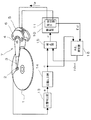
第1の解決手段として、本発明によるディスク装置は、次のような複数の構成要素を備えている。すなわち、
ディスクに対してヘッドの位置決めを行うアクチュエータ手段と、
前記アクチュエータ手段の駆動手段と、
前記アクチュエータ手段の駆動において発生する電圧を検出し電圧信号を出力する電圧検出手段と、
前記駆動手段における駆動信号と前記電圧信号から前記ヘッドに加わる外乱の大きさを推定し外乱推定信号を生成する外乱推定手段と、
前記ディスクに予め記録され前記ヘッドにより検出されるサーボ情報から前記ヘッドの現在位置に対応した位置誤差信号を生成する位置検出手段と、
前記位置誤差信号に対応した位置制御信号を生成する位置制御手段と、
前記位置制御信号と前記外乱推定信号より前記駆動信号を合成する補正手段と
を具備している。
As a first solution, the disk device according to the present invention includes a plurality of components as follows. That is,
Actuator means for positioning the head relative to the disk;
Driving means for the actuator means;
Voltage detection means for detecting a voltage generated in driving the actuator means and outputting a voltage signal;
Disturbance estimation means for estimating the magnitude of disturbance applied to the head from the drive signal and the voltage signal in the drive means, and generating a disturbance estimation signal;
Position detecting means for generating a position error signal corresponding to the current position of the head from servo information recorded in advance on the disk and detected by the head;
Position control means for generating a position control signal corresponding to the position error signal;
And correction means for synthesizing the drive signal from the position control signal and the disturbance estimation signal.
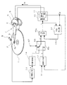
さらに、前記外乱推定手段は、
当該外乱推定手段で生成する電圧推定信号を前記電圧信号と比較し偏差信号を出力する比較手段と、
前記偏差信号を積分した積分信号に第1の係数を乗算した信号と前記偏差信号に比例した比例信号に第2の係数を乗算した信号とを加算し前記外乱推定信号を生成する加算手段と
を備えている。
Further, the disturbance estimation means includes:
A comparison means for comparing the voltage estimation signal generated by the disturbance estimation means with the voltage signal and outputting a deviation signal;
Adding means for adding the signal obtained by multiplying the integral signal obtained by integrating the deviation signal by the first coefficient and the signal obtained by multiplying the proportional signal proportional to the deviation signal by the second coefficient to generate the disturbance estimation signal; I have.
なお、この構成において、駆動手段における駆動信号としては、駆動手段に入力するものであってもよいし、あるいは、駆動手段から出力するものであってもよく、この点は以下でも同様である。 In this configuration, the drive signal in the drive means may be input to the drive means or may be output from the drive means, and this is the same in the following.
この第1の解決手段による作用は次のとおりである。外乱推定手段は、アクチュエータ手段の駆動手段に与える駆動信号とアクチュエータ手段から検出した電圧信号とに基づいて、アクチュエータ手段にかかる外乱(軸受摩擦、電子回路基板と接続するFPCの弾性力、外部から加わる衝撃や振動に起因する慣性力など)の大きさを推定する。ここで、電圧推定信号と電圧信号の差分である偏差信号の積分信号のみに基づいて外乱推定信号を生成するのではなく、偏差信号の比例信号も利用して、積分信号と比例信号とを一定の比率で加算して外乱推定信号を生成する〔τdest=k1・a+k2・b〕。これにより、実際の外乱に対する外乱推定信号の位相遅れを軽減し、実際の外乱に対してより近づけた状態の外乱推定信号を生成することができる。この位相遅れの抑制された正確に推定した外乱推定信号をもってアクチュエータ手段に加わる外乱を打ち消すように、その外乱推定信号を位置制御信号に合成して駆動信号を生成する。その駆動信号をもってヘッドのアクチュエータ手段を駆動することにより、アクチュエータ手段に加わる外乱を打ち消し、外乱に対する補償を良好に行うことができるので、目標トラックに向かうフォローイング動作時に外乱の変動が大きくても、ヘッドの目標トラックへの位置決め制御を安定に行うことができる。 The operation of the first solving means is as follows. The disturbance estimation means applies a disturbance applied to the actuator means (bearing friction, elastic force of the FPC connected to the electronic circuit board, externally applied) based on the drive signal applied to the drive means of the actuator means and the voltage signal detected from the actuator means. Estimate the magnitude of the inertia force caused by shock or vibration). Here, the disturbance estimation signal is not generated based only on the integration signal of the deviation signal, which is the difference between the voltage estimation signal and the voltage signal, but the integration signal and the proportional signal are kept constant by using the proportional signal of the deviation signal. To generate a disturbance estimation signal [τdest = k 1 · a + k 2 · b]. Thereby, the phase delay of the disturbance estimation signal with respect to the actual disturbance can be reduced, and the disturbance estimation signal in a state closer to the actual disturbance can be generated. The disturbance estimation signal is combined with the position control signal to generate a drive signal so as to cancel the disturbance applied to the actuator means with the accurately estimated disturbance estimation signal with the phase delay suppressed. By driving the actuator means of the head with the drive signal, the disturbance applied to the actuator means can be canceled and compensation for the disturbance can be satisfactorily performed, so even if the fluctuation of the disturbance is large during the following operation toward the target track, Positioning control of the head to the target track can be stably performed.
上記第1の解決手段をディスク装置の制御方法として記述すると、次のようになる。すなわち、
ディスクに予め記録されてヘッドにより検出されるサーボ情報から前記ヘッドの現在位置に対応した位置誤差信号を生成し、
前記位置誤差信号に対応した位置制御信号を生成し、
前記ヘッドの位置決めを行うアクチュエータ手段の駆動信号と前記アクチュエータ手段の駆動において発生する電圧信号とに基づいて前記電圧信号の推定である電圧推定信号を生成し、
前記電圧推定信号と前記電圧信号とを比較してその差分の偏差信号を生成し、
前記偏差信号を積分した積分信号に第1の係数を乗算した信号と前記偏差信号に比例した比例信号に第2の係数を乗算した信号とを加算することにより外乱推定信号を生成し、
前記位置制御信号と前記外乱推定信号とを合成して前記駆動信号を生成し、
前記駆動信号により前記アクチュエータ手段を駆動して前記ディスクに対する前記ヘッドの位置決めを行う。
The first solving means is described as a disk device control method as follows. That is,
A position error signal corresponding to the current position of the head is generated from servo information recorded in advance on the disk and detected by the head,
Generating a position control signal corresponding to the position error signal;
Generating a voltage estimation signal that is an estimation of the voltage signal based on a drive signal of the actuator means for positioning the head and a voltage signal generated in driving the actuator means;
Comparing the voltage estimation signal and the voltage signal to generate a deviation signal of the difference,
A disturbance estimation signal is generated by adding a signal obtained by multiplying the integral signal obtained by integrating the deviation signal by a first coefficient and a signal obtained by multiplying a proportional signal proportional to the deviation signal by a second coefficient;
The position control signal and the disturbance estimation signal are combined to generate the drive signal,
The actuator means is driven by the drive signal to position the head with respect to the disk.
このディスク装置の制御方法によれば、上記同様の作用を発揮する。 According to this disk device control method, the same effect as described above is exhibited.
第2の解決手段として、本発明によるディスク装置は、次のような複数の構成要素を備えている。すなわち、
ディスクに対してヘッドの位置決めを行うアクチュエータ手段と、
前記アクチュエータ手段の駆動手段と、
前記アクチュエータ手段の駆動において発生する電圧を検出し電圧信号を出力する電圧検出手段と、
前記駆動手段における駆動信号と前記電圧信号から前記ヘッドに加わる外乱の大きさを推定し外乱推定信号を生成する外乱推定手段と、
前記ディスクに予め記録され前記ヘッドにより検出されるサーボ情報から前記ヘッドの現在位置に対応した位置誤差信号を生成する位置検出手段と、
前記位置誤差信号に対応した位置制御信号を生成する位置制御手段と、
前記位置制御信号と前記外乱推定信号より前記駆動信号を合成する補正手段と
を具備している。
As a second solution, the disk device according to the present invention includes the following plural components. That is,
Actuator means for positioning the head relative to the disk;
Driving means for the actuator means;
Voltage detection means for detecting a voltage generated in driving the actuator means and outputting a voltage signal;
Disturbance estimation means for estimating the magnitude of disturbance applied to the head from the drive signal and the voltage signal in the drive means, and generating a disturbance estimation signal;
Position detecting means for generating a position error signal corresponding to the current position of the head from servo information recorded in advance on the disk and detected by the head;
Position control means for generating a position control signal corresponding to the position error signal;
And correction means for synthesizing the drive signal from the position control signal and the disturbance estimation signal.
さらに、前記外乱推定手段は、
当該外乱推定手段で生成する電圧推定信号を前記電圧信号と比較し偏差信号を出力する比較手段と、
前記偏差信号に比例した比例信号の高域周波数成分を遮断しフィルタ出力信号を生成するフィルタ手段と、
前記偏差信号を積分した積分信号に第1の係数を乗算した信号と前記フィルタ出力信号に第2の係数を乗算した信号とを加算し前記外乱推定信号を生成する加算手段と
を備えている。
Further, the disturbance estimation means includes:
A comparison means for comparing the voltage estimation signal generated by the disturbance estimation means with the voltage signal and outputting a deviation signal;
Filter means for cutting off a high frequency component of a proportional signal proportional to the deviation signal and generating a filter output signal;
And adding means for adding the signal obtained by multiplying the integral signal obtained by integrating the deviation signal by the first coefficient and the signal obtained by multiplying the filter output signal by the second coefficient to generate the disturbance estimation signal.
この第2の解決手段による作用は、基本的には上記第1の解決手段と同様である。そして外乱推定手段にフィルタ手段を付加したことにより、ノイズを低減することができる。フィルタ手段は、比例信号の高域周波数成分を遮断してフィルタ出力信号を生成する。一方、積分信号は、偏差信号を積分する過程で高域周波数成分が遮断される。これは、積分自体が一種の高域遮断フィルタであることによる。したがって、積分信号とフィルタ出力信号とを合成して得られる外乱推定信号は高域成分を除去されたノイズの少ない信号となる。また、位置決め制御系に外乱推定手段を適用したときの制御系全体の安定性を向上させることができる。 The operation of the second solving means is basically the same as that of the first solving means. And noise can be reduced by adding the filter means to the disturbance estimating means. The filter means generates a filter output signal by cutting off a high frequency component of the proportional signal. On the other hand, the high frequency component of the integrated signal is cut off in the process of integrating the deviation signal. This is because the integration itself is a kind of high-frequency cutoff filter. Therefore, the disturbance estimation signal obtained by synthesizing the integration signal and the filter output signal is a signal with less noise from which high-frequency components are removed. Further, the stability of the entire control system can be improved when the disturbance estimation means is applied to the positioning control system.
上記第2の解決手段をディスク装置の制御方法として記述すると、次のようになる。すなわち、
ディスクに予め記録されてヘッドにより検出されるサーボ情報から前記ヘッドの現在位置に対応した位置誤差信号を生成し、
前記位置誤差信号に対応した位置制御信号を生成し、
前記ヘッドの位置決めを行うアクチュエータ手段の駆動信号と前記アクチュエータ手段の駆動において発生する電圧信号とに基づいて前記電圧信号の推定である電圧推定信号を生成し、
前記電圧推定信号と前記電圧信号とを比較してその差分の偏差信号を生成し、
前記偏差信号を積分した積分信号に第1の係数を乗算した信号と前記偏差信号に比例した比例信号の高域周波数成分を遮断したフィルタ出力信号に第2の係数を乗算した信号とを加算することにより外乱推定信号を生成し、
前記位置制御信号と前記外乱推定信号とを合成して前記駆動信号を生成し、
前記駆動信号により前記アクチュエータ手段を駆動して前記ディスクに対する前記ヘッドの位置決めを行う。
The second solving means is described as a disk device control method as follows. That is,
A position error signal corresponding to the current position of the head is generated from servo information recorded in advance on the disk and detected by the head,
Generating a position control signal corresponding to the position error signal;
Generating a voltage estimation signal that is an estimation of the voltage signal based on a drive signal of the actuator means for positioning the head and a voltage signal generated in driving the actuator means;
Comparing the voltage estimation signal and the voltage signal to generate a deviation signal of the difference,
A signal obtained by multiplying the integral signal obtained by integrating the deviation signal by the first coefficient and a filter output signal obtained by blocking the high frequency component of the proportional signal proportional to the deviation signal are added to the signal multiplied by the second coefficient. To generate a disturbance estimation signal,
The position control signal and the disturbance estimation signal are combined to generate the drive signal,
The actuator means is driven by the drive signal to position the head with respect to the disk.
このディスク装置の制御方法によれば、上記同様の作用を発揮する。 According to this disk device control method, the same effect as described above is exhibited.
上記の第1または第2の解決手段において、次のように構成することは好ましいものである。すなわち、
前記外乱推定手段の構成につき、前記電圧検出手段の検出した電圧信号が入力される比較手段と、
前記駆動信号に第1の伝達関数からなる係数を乗算する第1の乗算手段と、
前記比較手段の出力に第2の伝達関数からなる係数を乗算する第2の乗算手段と、
前記比較手段の出力を積分する第1の積分手段と、
前記第1の乗算手段の出力から前記第2の乗算手段の出力と前記第1の積分手段の出力との加算値を減算した値を積分する第2の積分手段と
を具備した構成とする。
In the first or second solving means described above, it is preferable to configure as follows. That is,
Comparing means for inputting the voltage signal detected by the voltage detecting means for the configuration of the disturbance estimating means,
First multiplication means for multiplying the drive signal by a coefficient comprising a first transfer function;
Second multiplication means for multiplying the output of the comparison means by a coefficient comprising a second transfer function;
First integrating means for integrating the output of the comparing means;
And a second integration unit that integrates a value obtained by subtracting an addition value of the output of the second multiplication unit and the output of the first integration unit from the output of the first multiplication unit.
さらに、前記比較手段が前記第2の積分手段の出力と前記電圧信号とを比較し、その差分を前記第2の乗算手段と前記第1の積分手段へ出力するように構成されている。 Further, the comparison means compares the output of the second integration means with the voltage signal and outputs the difference to the second multiplication means and the first integration means.
この構成による作用は次のとおりである。駆動信号を入力する第1の乗算手段の出力は、アクチュエータ手段に作用する駆動トルクに対応した駆動トルク推定信号となる。第2の積分手段の出力は、電圧検出手段の検出した電圧信号に対する電圧推定信号となる。第2の積分手段からの電圧推定信号と電圧信号との差分をとる比較手段が出力する偏差信号は、第1の積分手段と第2の乗算手段に与えられる。前記の第2の乗算手段の出力と前記の第1の積分手段の出力との加算値を前記の第1の乗算手段の出力から減算して第2の積分手段に与える。前記の偏差信号を積分した積分信号と前記の偏差信号に比例した比例信号とを一定の比率で加算して得られた信号は外乱推定信号となる。 The effect | action by this structure is as follows. The output of the first multiplication means for inputting the drive signal is a drive torque estimation signal corresponding to the drive torque acting on the actuator means. The output of the second integration means is a voltage estimation signal for the voltage signal detected by the voltage detection means. The deviation signal output from the comparison means that takes the difference between the voltage estimation signal from the second integration means and the voltage signal is provided to the first integration means and the second multiplication means. The addition value of the output of the second multiplication means and the output of the first integration means is subtracted from the output of the first multiplication means and provided to the second integration means. A signal obtained by adding an integral signal obtained by integrating the deviation signal and a proportional signal proportional to the deviation signal at a constant ratio is a disturbance estimation signal.
以上の結果として、生成された外乱推定信号は、アクチュエータ手段が受ける外乱を正確に推定したものに相当している。そして、このように正確に割り出した外乱推定信号をもって外乱を打ち消すようフィードフォワード制御を行うので、フォローイング動作において外乱に対する補償を良好に行うことができ、フォローイング動作時に外乱の変動が大きくても、目標トラックに対するヘッドの位置決め制御を安定に行い、位置決め精度を向上させることができる。 As a result of the above, the generated disturbance estimation signal corresponds to an accurate estimation of the disturbance received by the actuator means. Since feedforward control is performed to cancel the disturbance with the disturbance estimation signal accurately determined in this way, it is possible to satisfactorily compensate for the disturbance in the following operation, even if the fluctuation of the disturbance is large during the following operation. Therefore, the head positioning control with respect to the target track can be stably performed, and the positioning accuracy can be improved.
第3の解決手段として、本発明によるディスク装置は、次のような複数の構成要素を備えている。すなわち、
ディスクに対してヘッドの位置決めを行うアクチュエータ手段と、
前記アクチュエータ手段の駆動手段と、
前記アクチュエータ手段の駆動において発生する電圧を検出し電圧信号を出力する電圧検出手段と、
前記ディスクに予め記録され前記ヘッドにより検出されるサーボ情報から前記ヘッドの現在位置に対応した位置誤差信号を生成する位置検出手段と、
前記位置誤差信号に対応した位置制御信号を生成する位置制御手段と、
前記位置制御信号と前記電圧信号から前記ヘッドに加わる外乱の大きさを推定し外乱推定信号を生成する外乱推定手段と、
前記位置制御信号と前記外乱推定信号より前記駆動信号を合成する補正手段と
を具備している。
As a third solution, the disk device according to the present invention includes a plurality of components as follows. That is,
Actuator means for positioning the head relative to the disk;
Driving means for the actuator means;
Voltage detection means for detecting a voltage generated in driving the actuator means and outputting a voltage signal;
Position detecting means for generating a position error signal corresponding to the current position of the head from servo information recorded in advance on the disk and detected by the head;
Position control means for generating a position control signal corresponding to the position error signal;
Disturbance estimation means for estimating a magnitude of disturbance applied to the head from the position control signal and the voltage signal and generating a disturbance estimation signal;
And correction means for synthesizing the drive signal from the position control signal and the disturbance estimation signal.
さらに、前記外乱推定手段は、
当該外乱推定手段で生成する電圧推定信号を前記電圧信号と比較し偏差信号を出力する比較手段と、
前記偏差信号を積分した積分信号に第1の係数を乗算した信号と前記偏差信号に比例した比例信号に第2の係数を乗算した信号とを加算し前記外乱推定信号を生成する加算手段と
を備えている。
Further, the disturbance estimation means includes:
A comparison means for comparing the voltage estimation signal generated by the disturbance estimation means with the voltage signal and outputting a deviation signal;
Adding means for adding the signal obtained by multiplying the integral signal obtained by integrating the deviation signal by the first coefficient and the signal obtained by multiplying the proportional signal proportional to the deviation signal by the second coefficient to generate the disturbance estimation signal; I have.
この第3の解決手段による作用は次のとおりである。外乱推定手段に入力する要素が、第1の解決手段では電圧信号と駆動信号であるのに対して、本解決手段では電圧信号と位置制御信号とを外乱推定手段に入力している。外乱推定手段は、位置制御手段からの位置制御信号とアクチュエータ手段から検出した電圧信号とに基づいて、アクチュエータ手段が受ける外乱の大きさを正確に推定する。ここで、電圧推定信号と電圧信号の差分である偏差信号の積分信号のみに基づいて外乱推定信号を生成するのではなく、偏差信号の比例信号も利用して、積分信号と比例信号とを一定の比率で加算して外乱推定信号を生成する〔τdest=k1・a+k2・b〕。これにより、実際の外乱に対する外乱推定信号の位相遅れを軽減し、実際の外乱に対してより近づけた状態の外乱推定信号を生成することができる。この位相遅れの抑制された正確に推定した外乱推定信号をもって外乱を打ち消すように、その外乱推定信号を位置制御手段が出力する位置制御信号に合成して駆動信号を生成する。その駆動信号をもってヘッドのアクチュエータ手段を駆動することにより外乱を打ち消し、外乱に対する補償を良好に行うことができるので、目標トラックに向かうフォローイング動作時に外乱の変動が大きくても、ヘッドの目標トラックへの位置決め制御を安定に行うことができる。 The operation of the third solving means is as follows. The elements input to the disturbance estimating means are the voltage signal and the drive signal in the first solving means, whereas in this solving means, the voltage signal and the position control signal are input to the disturbance estimating means. The disturbance estimation means accurately estimates the magnitude of the disturbance received by the actuator means based on the position control signal from the position control means and the voltage signal detected from the actuator means. Here, the disturbance estimation signal is not generated based only on the integration signal of the deviation signal, which is the difference between the voltage estimation signal and the voltage signal, but the integration signal and the proportional signal are kept constant by using the proportional signal of the deviation signal. To generate a disturbance estimation signal [τdest = k 1 · a + k 2 · b]. Thereby, the phase delay of the disturbance estimation signal with respect to the actual disturbance can be reduced, and the disturbance estimation signal in a state closer to the actual disturbance can be generated. The disturbance estimation signal is combined with the position control signal output from the position control means to generate a drive signal so as to cancel the disturbance with the accurately estimated disturbance estimation signal with the phase delay suppressed. By driving the actuator means of the head with the drive signal, the disturbance can be canceled out and the compensation for the disturbance can be satisfactorily performed, so even if the fluctuation of the disturbance during the following operation toward the target track is large, the target track of the head Can be stably controlled.
上記第3の解決手段をディスク装置の制御方法として記述すると、次のようになる。すなわち、
ディスクに予め記録されてヘッドにより検出されるサーボ情報から前記ヘッドの現在位置に対応した位置誤差信号を生成し、
前記位置誤差信号に対応した位置制御信号を生成し、
前記位置制御信号と前記アクチュエータ手段の駆動において発生する電圧信号とから前記電圧信号の推定である電圧推定信号を生成し、
前記電圧推定信号と前記電圧信号とを比較してその差分の偏差信号を生成し、
前記偏差信号を積分した積分信号に第1の係数を乗算した信号と前記偏差信号に比例した比例信号に第2の係数を乗算した信号とを加算することにより外乱推定信号を生成し、
前記位置制御信号と前記外乱推定信号とを合成して前記駆動信号を生成し、
前記駆動信号により前記アクチュエータ手段を駆動して前記ディスクに対する前記ヘッドの位置決めを行う。
The third solution can be described as a disk device control method as follows. That is,
A position error signal corresponding to the current position of the head is generated from servo information recorded in advance on the disk and detected by the head,
Generating a position control signal corresponding to the position error signal;
Generating a voltage estimation signal that is an estimate of the voltage signal from the position control signal and a voltage signal generated in driving the actuator means;
Comparing the voltage estimation signal and the voltage signal to generate a deviation signal of the difference,
A disturbance estimation signal is generated by adding a signal obtained by multiplying the integral signal obtained by integrating the deviation signal by a first coefficient and a signal obtained by multiplying a proportional signal proportional to the deviation signal by a second coefficient;
The position control signal and the disturbance estimation signal are combined to generate the drive signal,
The actuator means is driven by the drive signal to position the head with respect to the disk.
このディスク装置の制御方法によれば、上記同様の作用を発揮する。 According to this disk device control method, the same effect as described above is exhibited.
第4の解決手段として、発明によるディスク装置は、ディスクに対してヘッドの位置決めを行うアクチュエータ手段と、
前記アクチュエータ手段の駆動手段と、
前記アクチュエータ手段の駆動において発生する電圧を検出し電圧信号を出力する電圧検出手段と、
前記ディスクに予め記録され前記ヘッドにより検出されるサーボ情報から前記ヘッドの現在位置に対応した位置誤差信号を生成する位置検出手段と、
前記位置誤差信号に対応した位置制御信号を生成する位置制御手段と、
前記位置制御信号と前記電圧信号から前記ヘッドに加わる外乱の大きさを推定し外乱推定信号を生成する外乱推定手段と、
前記位置制御信号と前記外乱推定信号より前記駆動信号を合成する補正手段と
を具備している。
As a fourth solution, the disk device according to the invention comprises an actuator means for positioning the head with respect to the disk;
Driving means for the actuator means;
Voltage detection means for detecting a voltage generated in driving the actuator means and outputting a voltage signal;
Position detecting means for generating a position error signal corresponding to the current position of the head from servo information recorded in advance on the disk and detected by the head;
Position control means for generating a position control signal corresponding to the position error signal;
Disturbance estimation means for estimating a magnitude of disturbance applied to the head from the position control signal and the voltage signal and generating a disturbance estimation signal;
And correction means for synthesizing the drive signal from the position control signal and the disturbance estimation signal.
さらに、前記外乱推定手段は、
当該外乱推定手段で生成する電圧推定信号を前記電圧信号と比較し偏差信号を出力する比較手段と、
前記偏差信号に比例した比例信号の高域周波数成分を遮断しフィルタ出力信号を生成するフィルタ手段と、
前記偏差信号を積分した積分信号に第1の係数を乗算した信号と前記フィルタ出力信号に第2の係数を乗算した信号とを加算し前記外乱推定信号を生成する加算手段と
を備えている。
Further, the disturbance estimation means includes:
A comparison means for comparing the voltage estimation signal generated by the disturbance estimation means with the voltage signal and outputting a deviation signal;
Filter means for cutting off a high frequency component of a proportional signal proportional to the deviation signal and generating a filter output signal;
And adding means for adding the signal obtained by multiplying the integral signal obtained by integrating the deviation signal by the first coefficient and the signal obtained by multiplying the filter output signal by the second coefficient to generate the disturbance estimation signal.
この第4の解決手段による作用は、基本的に上記第3の解決手段と同様である。そして外乱推定手段にフィルタ手段を付加したことにより、ノイズを低減することができる。フィルタ手段は、比例信号の高域周波数成分を遮断してフィルタ出力信号を生成する。一方、積分信号は、偏差信号を積分する過程で高域周波数成分が遮断される。これは、積分自体が一種の高域遮断フィルタであることによる。したがって、積分信号とフィルタ出力信号とを合成して得られる高域成分を除去されたノイズの少ない信号となる。また、位置決め制御系に外乱推定手段を適用したときの制御系全体の安定性を向上させることができる。 The operation of the fourth solving means is basically the same as that of the third solving means. And noise can be reduced by adding the filter means to the disturbance estimating means. The filter means generates a filter output signal by cutting off a high frequency component of the proportional signal. On the other hand, the high frequency component of the integrated signal is cut off in the process of integrating the deviation signal. This is because the integration itself is a kind of high-frequency cutoff filter. Therefore, a signal with less noise from which a high frequency component obtained by synthesizing the integration signal and the filter output signal is removed is obtained. Further, the stability of the entire control system can be improved when the disturbance estimation means is applied to the positioning control system.
上記第4の解決手段をディスク装置の制御方法として記述すると、次のようになる。すなわち、
ディスクに予め記録されてヘッドにより検出されるサーボ情報から前記ヘッドの現在位置に対応した位置誤差信号を生成し、
前記位置誤差信号に対応した位置制御信号を生成し、
前記位置制御信号と前記アクチュエータ手段の駆動において発生する電圧信号とから前記電圧信号の推定である電圧推定信号を生成し、
前記電圧推定信号と前記電圧信号とを比較してその差分の偏差信号を生成し、
前記偏差信号を積分した積分信号に第1の係数を乗算した信号と前記偏差信号に比例した比例信号の高域周波数成分を遮断したフィルタ出力信号に第2の係数を乗算した信号とを加算することにより外乱推定信号を生成し、
前記位置制御信号と前記外乱推定信号とを合成して前記駆動信号を生成し、
前記駆動信号により前記アクチュエータ手段を駆動して前記ディスクに対する前記ヘッドの位置決めを行う。
The fourth solution can be described as a disk device control method as follows. That is,
A position error signal corresponding to the current position of the head is generated from servo information recorded in advance on the disk and detected by the head,
Generating a position control signal corresponding to the position error signal;
Generating a voltage estimation signal that is an estimate of the voltage signal from the position control signal and a voltage signal generated in driving the actuator means;
Comparing the voltage estimation signal and the voltage signal to generate a deviation signal of the difference,
A signal obtained by multiplying the integral signal obtained by integrating the deviation signal by the first coefficient and a filter output signal obtained by blocking the high frequency component of the proportional signal proportional to the deviation signal are added to the signal multiplied by the second coefficient. To generate a disturbance estimation signal,
The position control signal and the disturbance estimation signal are combined to generate the drive signal,
The actuator means is driven by the drive signal to position the head with respect to the disk.
このディスク装置の制御方法によれば、上記同様の作用を発揮する。 According to this disk device control method, the same effect as described above is exhibited.
上記の第3または第4の解決手段において、次のように構成することは好ましいものである。すなわち、
前記外乱推定手段は、
前記電圧検出手段の検出した電圧信号が入力される比較手段と、
前記位置制御信号に第1の伝達関数からなる係数を乗算する第1の乗算手段と、
前記比較手段の出力に第2の伝達関数からなる係数を乗算する第2の乗算手段と、
前記比較手段の出力を積分する第1の積分手段と、
前記第1の乗算手段の出力から前記第2の乗算手段の出力と前記第1の積分手段の出力との加算値を減算した値を積分する第2の積分手段と
を具備し、前記比較手段が前記第2の積分手段の出力と前記電圧信号とを比較し、その差分を前記第2の乗算手段と前記第1の積分手段へ出力するように構成している。ここでの特徴は、第1の乗算手段に入力するのが位置制御信号となっている点である。
In the third or fourth solving means described above, it is preferable to configure as follows. That is,
The disturbance estimation means includes:
A comparison means for inputting a voltage signal detected by the voltage detection means;
First multiplying means for multiplying the position control signal by a coefficient comprising a first transfer function;
Second multiplication means for multiplying the output of the comparison means by a coefficient comprising a second transfer function;
First integrating means for integrating the output of the comparing means;
A second integration unit that integrates a value obtained by subtracting an addition value of the output of the second multiplication unit and the output of the first integration unit from the output of the first multiplication unit; Compares the output of the second integration means and the voltage signal, and outputs the difference to the second multiplication means and the first integration means. The feature here is that the position control signal is input to the first multiplication means.
この構成による作用は次のとおりである。位置制御信号を入力する第1の乗算手段の出力は、アクチュエータ手段に作用する駆動トルクに対応した駆動トルク推定信号となる。第2の積分手段の出力は、電圧検出手段の検出した電圧信号に対する電圧推定信号となる。第2の積分手段からの電圧推定信号との差分をとる比較手段の出力する偏差信号は、第1の積分手段と第2の乗算手段に与えられる。前記の第2の乗算手段の出力と前記の第1の積分手段の出力との加算値を前記の第1の乗算手段の出力から減算して第2の積分手段に与える。前記の偏差信号を積分した積分信号と前記の偏差信号に比例した比例信号とを一定の比率で加算して得られた信号は外乱推定信号となる。 The effect | action by this structure is as follows. The output of the first multiplication means that inputs the position control signal is a drive torque estimation signal corresponding to the drive torque that acts on the actuator means. The output of the second integration means is a voltage estimation signal for the voltage signal detected by the voltage detection means. The deviation signal output from the comparison means that takes the difference from the voltage estimation signal from the second integration means is provided to the first integration means and the second multiplication means. The addition value of the output of the second multiplication means and the output of the first integration means is subtracted from the output of the first multiplication means and provided to the second integration means. A signal obtained by adding an integral signal obtained by integrating the deviation signal and a proportional signal proportional to the deviation signal at a constant ratio is a disturbance estimation signal.
以上の結果として、生成された外乱推定信号は、アクチュエータ手段が受ける外乱を正確に推定したものに相当している。そして、このように正確に割り出した外乱推定信号をもって外乱を打ち消すようフィードフォワード制御を行うので、フォローイング動作において外乱に対する補償を良好に行うことができ、フォローイング動作時に外乱の変動が大きくても、目標トラックに対するヘッドの位置決め制御を安定に行い、位置決め精度を向上させることができる。 As a result of the above, the generated disturbance estimation signal corresponds to an accurate estimation of the disturbance received by the actuator means. Since feedforward control is performed to cancel the disturbance with the disturbance estimation signal accurately determined in this way, it is possible to satisfactorily compensate for the disturbance in the following operation, even if the fluctuation of the disturbance is large during the following operation. Therefore, the head positioning control with respect to the target track can be stably performed, and the positioning accuracy can be improved.
さらに、上記の解決手段で必要とした第1の積分手段と第2の乗算手段との加算を行う必要がなく、その加算のための手段を省略することが可能で、構成の簡素化をもたらすことができる。 Further, there is no need to add the first integration means and the second multiplication means required in the above solution means, and the means for the addition can be omitted, resulting in a simplified configuration. be able to.
上記の各解決手段において、外乱推定信号を生成する演算式の第1の係数(k1)と第2の係数(k2)について、次のように設定することは好ましい。 In each of the above solutions, it is preferable to set the first coefficient (k 1 ) and the second coefficient (k 2 ) of the arithmetic expression for generating the disturbance estimation signal as follows.
すなわち、前記第1の係数(k1)と前記第2の係数(k2)との比率(=k2/k1)が略ωo2 /(ωo2−ωd2) (ただし、ωoは前記外乱推定手段の推定周波数、ωdは外乱周波数)となるように設定されていることである。 That is, the first coefficient (k 1) the ratio between said second coefficient (k 2) (= k 2 / k 1) is substantially ωo 2 / (ωo 2 -ωd 2 ) ( however, .omega.o is the The estimated frequency of the disturbance estimation means, ωd, is set to be the disturbance frequency).
これによれば、外乱に対する外乱推定信号の位相遅れを実質的にゼロにでき、外乱推定信号は外乱をきわめて正確に推定したものとなる。 According to this, the phase lag of the disturbance estimation signal with respect to the disturbance can be made substantially zero, and the disturbance estimation signal is an estimate of the disturbance very accurately.
また、前記第1の係数を1に設定する場合には、乗算器や加算器を削減でき、構成の簡素化を実現する。 Further, when the first coefficient is set to 1, the number of multipliers and adders can be reduced, and the configuration can be simplified.
上記において好ましい態様は、前記外乱推定手段の制御帯域が、前記位置制御手段の制御帯域よりも大きく設定されていることである。 A preferable aspect in the above is that the control band of the disturbance estimation unit is set larger than the control band of the position control unit.
これによる作用は次のとおりである。位置決め制御系の制御帯域を広げることは比例のゲインを大きくすることであるが、ディスク装置のセクタサーボのサンプリング周波数やがもつ固有機械共振周波数によって上限が存在することになる。これに対して、外乱推定手段ではディスク装置のセクタサーボのサンプリング周波数の影響を受けない。したがって、外乱推定手段においては、その制御帯域(推定周波数)を位置決め制御系の制御帯域よりも高く設定することができる。その結果として、より高い制御帯域にわたって、ヘッドを目標トラックに対して正確に追従させることができる。 The effect | action by this is as follows. To widen the control band of the positioning control system is to increase the proportional gain, but there is an upper limit depending on the sampling frequency of the sector servo of the disk device and the inherent mechanical resonance frequency. On the other hand, the disturbance estimation means is not affected by the sampling frequency of the sector servo of the disk device. Therefore, in the disturbance estimation means, the control band (estimated frequency) can be set higher than the control band of the positioning control system. As a result, the head can accurately follow the target track over a higher control band.
ここまで説明してきた技術は、ディスクに対するヘッドのロード・アンロードの制御にも有利に展開することができる。以下、ロード・アンロードの制御の場合を説明する。 The technology described so far can be advantageously applied to control of loading / unloading of the head with respect to the disk. Hereinafter, the case of load / unload control will be described.
本発明のディスク装置は、
ディスクに対するヘッドのロード・アンロードを行うアクチュエータ手段と、
前記アクチュエータ手段の駆動手段と、
前記アクチュエータ手段の駆動において発生する電圧を検出し電圧信号を出力する電圧検出手段と、
前記駆動手段における駆動信号と前記電圧信号から前記ヘッドに加わる外乱の大きさを推定し外乱推定信号を生成する外乱推定手段と、
速度指令信号と前記電圧信号より速度制御信号を生成する速度制御手段と、
前記速度制御信号と前記外乱推定信号より前記駆動信号を合成する補正手段と
を具備している。
The disk device of the present invention comprises:
Actuator means for loading / unloading the head with respect to the disk;
Driving means for the actuator means;
Voltage detection means for detecting a voltage generated in driving the actuator means and outputting a voltage signal;
Disturbance estimation means for estimating the magnitude of disturbance applied to the head from the drive signal and the voltage signal in the drive means, and generating a disturbance estimation signal;
Speed control means for generating a speed control signal from the speed command signal and the voltage signal;
And correction means for synthesizing the drive signal from the speed control signal and the disturbance estimation signal.
さらに、前記外乱推定手段は、
当該外乱推定手段で生成する電圧推定信号を前記電圧信号と比較し偏差信号を出力する比較手段と、
前記偏差信号を積分した積分信号に第1の係数を乗算した信号と前記偏差信号に比例した比例信号に第2の係数を乗算した信号とを加算し前記外乱推定信号を生成する加算手段と
を備えている。
Further, the disturbance estimation means includes:
A comparison means for comparing the voltage estimation signal generated by the disturbance estimation means with the voltage signal and outputting a deviation signal;
Adding means for adding the signal obtained by multiplying the integral signal obtained by integrating the deviation signal by the first coefficient and the signal obtained by multiplying the proportional signal proportional to the deviation signal by the second coefficient to generate the disturbance estimation signal; I have.
電圧信号は位置の微分であって、速度情報を含んでいる。速度指令信号と電圧信号との差分で速度制御信号が作られる。また、ランプブロックなどのヘッド退避部材から受ける外乱を打ち消すために、その外乱の大きさを推定する。この外乱の大きさの推定に際して、2つの要素を用いる。1つは、アクチュエータ手段の駆動において発生する電圧を検出した電圧信号である。もう1つは、アクチュエータ手段の駆動手段における駆動信号である。ここで、駆動手段における駆動信号としては、駆動手段に入力するものであってもよいし、あるいは、駆動手段から出力するものであってもよい。また、駆動手段における駆動信号に代えて、その駆動信号を生成する基になる速度制御信号を用いてもよい。 The voltage signal is a derivative of the position and contains velocity information. A speed control signal is generated by the difference between the speed command signal and the voltage signal. Further, in order to cancel the disturbance received from the head retracting member such as the lamp block, the magnitude of the disturbance is estimated. Two elements are used in estimating the magnitude of the disturbance. One is a voltage signal obtained by detecting a voltage generated in driving the actuator means. The other is a drive signal in the drive means of the actuator means. Here, the drive signal in the drive unit may be input to the drive unit or may be output from the drive unit. Further, instead of the drive signal in the drive means, a speed control signal that is a basis for generating the drive signal may be used.
外乱の大きさを推定するための外乱推定手段を設ける。この外乱推定手段をもって、電圧検出手段が検出した電圧信号と駆動手段における駆動信号(速度制御信号の場合を含む)とを入力として、外乱推定信号を生成する。2つの要素に基づいて生成する外乱推定信号は、ヘッドに実際に加わる外乱の大きさを正確に推定したものとなる。 Disturbance estimation means for estimating the magnitude of the disturbance is provided. With this disturbance estimation means, a disturbance estimation signal is generated with the voltage signal detected by the voltage detection means and the drive signal (including the case of the speed control signal) in the drive means as inputs. The disturbance estimation signal generated based on the two factors is an accurate estimate of the magnitude of the disturbance actually applied to the head.
以上のようにして割り出した外乱推定信号を速度制御信号に合成して駆動信号を生成し、その駆動信号を用いてヘッドのアクチュエータ手段を駆動する。これにより、ヘッドに加わる外乱を良好に打ち消すので、ロード・アンロード時にヘッド退避部材上での外乱の変動が大きくても、速度制御を安定的に行うことができる。 The disturbance estimation signal determined as described above is combined with the speed control signal to generate a drive signal, and the actuator signal of the head is driven using the drive signal. Thereby, the disturbance applied to the head is satisfactorily canceled, so that the speed control can be stably performed even when the fluctuation of the disturbance on the head retracting member is large during loading / unloading.
本発明は、上記だけにとどまらず、さらに進んで次の点にも配慮している。 The present invention is not limited to the above, but goes further and considers the following points.
外乱推定手段は、入力されてくる電圧信号に相当する電圧推定信号を生成し、この電圧推定信号と入力の電圧信号とを比較し、その差分の偏差信号を生成する。さらに、この偏差信号を積分した積分信号と偏差信号に比例した比例信号を生成し、積分信号と比例信号との加算信号を前記電圧推定信号の生成のためにフィードバックし、偏差信号をゼロに近づける。 The disturbance estimation unit generates a voltage estimation signal corresponding to the input voltage signal, compares the voltage estimation signal with the input voltage signal, and generates a difference deviation signal. Further, an integral signal obtained by integrating the deviation signal and a proportional signal proportional to the deviation signal are generated, and an addition signal of the integral signal and the proportional signal is fed back to generate the voltage estimation signal, so that the deviation signal approaches zero. .
ここで、基礎的な考え方として、補正手段に戻す外乱推定信号の生成について、前記の積分信号のみに基づいて外乱推定信号を生成するという考え方がある。外乱推定信号を積分信号のみに基づいて生成する場合にも、外乱推定信号と位置制御信号とを合成した駆動信号でアクチュエータ手段を駆動すれば、上述の作用を発揮させて、外乱に対する補償を行うことはできる。 Here, as a basic idea, there is an idea that a disturbance estimation signal is generated based only on the integrated signal with respect to generation of the disturbance estimation signal to be returned to the correcting means. Even when the disturbance estimation signal is generated based only on the integral signal, if the actuator means is driven by a drive signal obtained by synthesizing the disturbance estimation signal and the position control signal, the above-described effect is exhibited and compensation for the disturbance is performed. I can.
しかし、外乱推定信号を積分信号のみに基づいて生成する場合には、その外乱推定信号と実際の外乱との間に位相差が生じ、外乱推定信号は実際の外乱に対して位相遅れを生じる。位相遅れを含む外乱推定信号に基づく駆動信号でアクチュエータ手段を駆動すれば、外乱に対する補償の効果は発揮されるものの、やはり位相遅れの影響がある。ここに改善の余地があり、本発明は、さらに進んで充分な補償を行うために次のような手段を追加している。 However, when the disturbance estimation signal is generated based only on the integral signal, a phase difference occurs between the disturbance estimation signal and the actual disturbance, and the disturbance estimation signal causes a phase lag with respect to the actual disturbance. If the actuator means is driven by a drive signal based on a disturbance estimation signal including a phase delay, the effect of compensation for the disturbance is exhibited, but there is still an influence of the phase delay. There is room for improvement here, and the present invention is further advanced to add the following means in order to perform sufficient compensation.
すなわち、前記の外乱推定手段において、前記の偏差信号の積分信号と偏差信号の比例信号とを一定の比率で加算して外乱推定信号を生成する。積分信号をa、比例信号をb、ともにゼロでない係数をk1,k2として、外乱推定信号τdestを、〔τdest=k1・a+k2・b〕と表すことができる。比例信号は積分信号に対して位相が90度進んだものとなっている。したがって、積分信号と比例信号とを適切に合成することにより、上記の位相遅れを軽減させることができる。すなわち、実際の外乱に対してより近づけた状態の外乱推定信号を生成することができる。この位相遅れが抑制された外乱推定信号を補正手段において位置制御信号と合成し、得られた駆動信号でアクチュエータ手段を駆動することにより、アクチュエータ手段に作用する軸受摩擦や弾性力や慣性力などの外乱に対する補償を充分良好に行うことができる。その結果、ロード・アンロード時にヘッド退避部材上での外乱の変動が大きくても、速度制御を安定的に行うことができる。すなわち、ヘッドロード・アンロード動作の信頼性を向上できる。なお、その副次的効果として、実質的に、トラック密度の向上を可能となし、大容量のディスク装置の実現化を促す。 That is, the disturbance estimation means adds the integral signal of the deviation signal and the proportional signal of the deviation signal at a constant ratio to generate a disturbance estimation signal. The disturbance estimation signal τdest can be expressed as [τdest = k 1 · a + k 2 · b], where a is the integral signal, b is the proportional signal, and k 1 and k 2 are both non-zero coefficients. The proportional signal has a phase advanced by 90 degrees with respect to the integral signal. Therefore, the phase delay can be reduced by appropriately combining the integral signal and the proportional signal. That is, it is possible to generate a disturbance estimation signal that is closer to the actual disturbance. The disturbance estimation signal in which the phase lag is suppressed is combined with the position control signal in the correction means, and the actuator means is driven by the obtained drive signal, so that the bearing friction, the elastic force, the inertial force, etc. acting on the actuator means are reduced. Compensation for disturbance can be sufficiently satisfactorily performed. As a result, speed control can be stably performed even when the fluctuation of the disturbance on the head retracting member is large during loading / unloading. That is, the reliability of the head load / unload operation can be improved. As a secondary effect, the track density can be substantially improved and the realization of a large capacity disk device is promoted.
以下、上記で説明した本発明をより具体的レベルで記述する。 Hereinafter, the present invention described above will be described at a more specific level.
第5の解決手段として、本発明によるディスク装置は、次のような複数の構成要素を備えている。すなわち、
ディスクに対するヘッドのロード・アンロードを行うアクチュエータ手段と、
前記アクチュエータ手段の駆動手段と、
前記アクチュエータ手段の駆動において発生する電圧を検出し電圧信号を出力する電圧検出手段と、
前記駆動手段における駆動信号と前記電圧信号から前記ヘッドに加わる外乱の大きさを推定し外乱推定信号を生成する外乱推定手段と、
速度指令信号と前記電圧信号より速度制御信号を生成する速度制御手段と、
前記速度制御信号と前記外乱推定信号より前記駆動信号を合成する補正手段と
を具備している。
As a fifth solution, the disk device according to the present invention includes the following plural components. That is,
Actuator means for loading / unloading the head with respect to the disk;
Driving means for the actuator means;
Voltage detection means for detecting a voltage generated in driving the actuator means and outputting a voltage signal;
Disturbance estimation means for estimating the magnitude of disturbance applied to the head from the drive signal and the voltage signal in the drive means, and generating a disturbance estimation signal;
Speed control means for generating a speed control signal from the speed command signal and the voltage signal;
And correction means for synthesizing the drive signal from the speed control signal and the disturbance estimation signal.
さらに、前記外乱推定手段は、
当該外乱推定手段で生成する電圧推定信号を前記電圧信号と比較し偏差信号を出力する比較手段と、
前記偏差信号を積分した積分信号に第1の係数を乗算した信号と前記偏差信号に比例した比例信号に第2の係数を乗算した信号とを加算し前記外乱推定信号を生成する加算手段と
を備えている。
Further, the disturbance estimation means includes:
A comparison means for comparing the voltage estimation signal generated by the disturbance estimation means with the voltage signal and outputting a deviation signal;
Adding means for adding the signal obtained by multiplying the integral signal obtained by integrating the deviation signal by the first coefficient and the signal obtained by multiplying the proportional signal proportional to the deviation signal by the second coefficient to generate the disturbance estimation signal; I have.
なお、この構成において、駆動手段における駆動信号としては、駆動手段に入力するものであってもよいし、あるいは、駆動手段から出力するものであってもよく、この点は以下でも同様である。 In this configuration, the drive signal in the drive means may be input to the drive means or may be output from the drive means, and this is the same in the following.
この第5の解決手段による作用は次のとおりである。外乱推定手段は、アクチュエータ手段の駆動手段に与える駆動信号とアクチュエータ手段から検出した電圧信号とに基づいて、アクチュエータ手段にかかる外乱(軸受摩擦、電子回路基板と接続するFPCの弾性力、外部から加わる衝撃や振動に起因する慣性力など)の大きさを推定する。ここで、電圧推定信号と電圧信号の差分である偏差信号の積分信号のみに基づいて外乱推定信号を生成するのではなく、偏差信号の比例信号も利用して、積分信号と比例信号とを一定の比率で加算して外乱推定信号を生成する〔τdest=k1・a+k2・b〕。これにより、実際の外乱に対してより近づけた状態の外乱推定信号を生成することができる。この位相遅れが抑制された外乱推定信号を補正手段において速度制御信号と合成し、得られた駆動信号でアクチュエータ手段を駆動することにより、アクチュエータ手段に作用する軸受摩擦や弾性力や慣性力などの外乱に対する補償を充分良好に行うことができる。その結果、ロード・アンロード時にヘッド退避部材上での外乱の変動が大きくても、速度制御を安定的に行うことができる。すなわち、ヘッドロード・アンロード動作の信頼性を向上できる。なお、その副次的効果として、実質的に、トラック密度の向上を可能となし、大容量のディスク装置の実現化を促す。 The operation of the fifth solving means is as follows. The disturbance estimation means applies a disturbance applied to the actuator means (bearing friction, elastic force of the FPC connected to the electronic circuit board, externally applied) based on the drive signal applied to the drive means of the actuator means and the voltage signal detected from the actuator means. Estimate the magnitude of the inertia force caused by shock or vibration). Here, the disturbance estimation signal is not generated based only on the integration signal of the deviation signal, which is the difference between the voltage estimation signal and the voltage signal, but the integration signal and the proportional signal are kept constant by using the proportional signal of the deviation signal. To generate a disturbance estimation signal [τdest = k 1 · a + k 2 · b]. Thereby, the disturbance estimation signal in a state closer to the actual disturbance can be generated. The disturbance estimation signal in which the phase delay is suppressed is combined with the speed control signal in the correction means, and the actuator means is driven with the obtained drive signal, so that the bearing friction, the elastic force, the inertial force, etc. acting on the actuator means are reduced. Compensation for disturbance can be sufficiently satisfactorily performed. As a result, speed control can be stably performed even when the fluctuation of the disturbance on the head retracting member is large during loading / unloading. That is, the reliability of the head load / unload operation can be improved. As a secondary effect, the track density can be substantially improved and the realization of a large capacity disk device is promoted.
上記第5の解決手段をディスク装置の制御方法として記述すると、次のようになる。すなわち、
速度指令に対応した速度制御信号を生成し、
ヘッドのロード・アンロードを行うアクチュエータ手段の駆動信号と前記アクチュエータ手段の駆動において発生する電圧信号とに基づいて前記電圧信号の推定である電圧推定信号を生成し、
前記電圧推定信号と前記電圧信号とを比較してその差分の偏差信号を生成し、
前記偏差信号を積分した積分信号に第1の係数を乗算した信号と前記偏差信号に比例した比例信号に第2の係数を乗算した信号とを加算することにより外乱推定信号を生成し、
前記速度制御信号と前記外乱推定信号とを合成して前記駆動信号を生成し、
前記駆動信号により前記アクチュエータ手段を駆動して前記ディスクに対する前記ヘッドのロード・アンロードを行う。
The fifth solution can be described as a disk device control method as follows. That is,
Generate a speed control signal corresponding to the speed command,
A voltage estimation signal that is an estimation of the voltage signal is generated based on a drive signal of the actuator means for loading / unloading the head and a voltage signal generated in driving the actuator means,
Comparing the voltage estimation signal and the voltage signal to generate a deviation signal of the difference,
A disturbance estimation signal is generated by adding a signal obtained by multiplying the integral signal obtained by integrating the deviation signal by a first coefficient and a signal obtained by multiplying a proportional signal proportional to the deviation signal by a second coefficient;
Combining the speed control signal and the disturbance estimation signal to generate the drive signal;
The actuator means is driven by the drive signal to load / unload the head with respect to the disk.
このディスク装置の制御方法によれば、上記同様の作用を発揮する。 According to this disk device control method, the same effect as described above is exhibited.
第6の解決手段として、本発明によるディスク装置は、次のような複数の構成要素を備えている。すなわち、
ディスクに対するヘッドのロード・アンロードを行うアクチュエータ手段と、
前記アクチュエータ手段の駆動手段と、
前記アクチュエータ手段の駆動において発生する電圧を検出し電圧信号を出力する電圧検出手段と、
前記駆動手段における駆動信号と前記電圧信号から前記ヘッドに加わる外乱の大きさを推定し外乱推定信号を生成する外乱推定手段と、
速度指令信号と前記電圧信号より速度制御信号を生成する速度制御手段と、
前記速度制御信号と前記外乱推定信号より前記駆動信号を合成する補正手段と
を具備している。
As a sixth solution, the disk device according to the present invention includes the following plurality of components. That is,
Actuator means for loading / unloading the head with respect to the disk;
Driving means for the actuator means;
Voltage detection means for detecting a voltage generated in driving the actuator means and outputting a voltage signal;
Disturbance estimation means for estimating the magnitude of disturbance applied to the head from the drive signal and the voltage signal in the drive means, and generating a disturbance estimation signal;
Speed control means for generating a speed control signal from the speed command signal and the voltage signal;
And correction means for synthesizing the drive signal from the speed control signal and the disturbance estimation signal.
さらに、前記外乱推定手段は、
当該外乱推定手段で生成する電圧推定信号を前記電圧信号と比較し偏差信号を出力する比較手段と、
前記偏差信号に比例した比例信号の高域周波数成分を遮断しフィルタ出力信号を生成するフィルタ手段と、
前記偏差信号を積分した積分信号に第1の係数を乗算した信号と前記フィルタ出力信号に第2の係数を乗算した信号とを加算し前記外乱推定信号を生成する加算手段と
を備えている。
Further, the disturbance estimation means includes:
A comparison means for comparing the voltage estimation signal generated by the disturbance estimation means with the voltage signal and outputting a deviation signal;
Filter means for cutting off a high frequency component of a proportional signal proportional to the deviation signal and generating a filter output signal;
And adding means for adding the signal obtained by multiplying the integral signal obtained by integrating the deviation signal by the first coefficient and the signal obtained by multiplying the filter output signal by the second coefficient to generate the disturbance estimation signal.
この第6の解決手段による作用は、基本的には上記第5の解決手段と同様である。そして外乱推定手段にフィルタ手段を付加したことにより、ノイズを低減することができる。フィルタ手段は、比例信号の高域周波数成分を遮断してフィルタ出力信号を生成する。一方、積分信号は、偏差信号を積分する過程で高域周波数成分が遮断される。これは、積分自体が一種の高域遮断フィルタであることによる。したがって、積分信号とフィルタ出力信号とを合成して得られる外乱推定信号は高域成分を除去されたノイズの少ない信号となる。また、速度制御系に外乱推定手段を適用したときの制御系全体の安定性を向上させることができる。 The operation of the sixth solving means is basically the same as that of the fifth solving means. And noise can be reduced by adding the filter means to the disturbance estimating means. The filter means generates a filter output signal by cutting off a high frequency component of the proportional signal. On the other hand, the high frequency component of the integrated signal is cut off in the process of integrating the deviation signal. This is because the integration itself is a kind of high-frequency cutoff filter. Therefore, the disturbance estimation signal obtained by synthesizing the integration signal and the filter output signal is a signal with less noise from which high-frequency components are removed. In addition, the stability of the entire control system can be improved when the disturbance estimation means is applied to the speed control system.
上記第6の解決手段をディスク装置の制御方法として記述すると、次のようになる。すなわち、
速度指令に対応した速度制御信号を生成し、
ヘッドのロード・アンロードを行うアクチュエータ手段の駆動信号と前記アクチュエータ手段の駆動において発生する電圧信号とに基づいて前記電圧信号の推定である電圧推定信号を生成し、
前記電圧推定信号と前記電圧信号とを比較してその差分の偏差信号を生成し、
前記偏差信号を積分した積分信号に第1の係数を乗算した信号と前記偏差信号に比例した比例信号の高域周波数成分を遮断したフィルタ出力信号に第2の係数を乗算した信号とを加算することにより外乱推定信号を生成し、
前記速度制御信号と前記外乱推定信号とを合成して前記駆動信号を生成し、
前記駆動信号により前記アクチュエータ手段を駆動して前記ディスクに対する前記ヘッドのロード・アンロードを行う。
The sixth solving means is described as a disk device control method as follows. That is,
Generate a speed control signal corresponding to the speed command,
A voltage estimation signal that is an estimation of the voltage signal is generated based on a drive signal of the actuator means for loading / unloading the head and a voltage signal generated in driving the actuator means,
Comparing the voltage estimation signal and the voltage signal to generate a deviation signal of the difference,
A signal obtained by multiplying the integral signal obtained by integrating the deviation signal by the first coefficient and a filter output signal obtained by blocking the high frequency component of the proportional signal proportional to the deviation signal are added to the signal multiplied by the second coefficient. To generate a disturbance estimation signal,
Combining the speed control signal and the disturbance estimation signal to generate the drive signal;
The actuator means is driven by the drive signal to load / unload the head with respect to the disk.
このディスク装置の制御方法によれば、上記同様の作用を発揮する。 According to this disk device control method, the same effect as described above is exhibited.
上記の第5または第6の解決手段において、次のように構成することは好ましいものである。すなわち、
前記外乱推定手段の構成につき、前記電圧検出手段の検出した電圧信号が入力される比較手段と、
前記駆動信号に第1の伝達関数からなる係数を乗算する第1の乗算手段と、
前記比較手段の出力に第2の伝達関数からなる係数を乗算する第2の乗算手段と、
前記比較手段の出力を積分する第1の積分手段と、
前記第1の乗算手段の出力から前記第2の乗算手段の出力と前記第1の積分手段の出力との加算値を減算した値を積分する第2の積分手段と
を具備した構成とする。
In the fifth or sixth solving means described above, the following configuration is preferable. That is,
Comparing means for inputting the voltage signal detected by the voltage detecting means for the configuration of the disturbance estimating means,
First multiplication means for multiplying the drive signal by a coefficient comprising a first transfer function;
Second multiplication means for multiplying the output of the comparison means by a coefficient comprising a second transfer function;
First integrating means for integrating the output of the comparing means;
And a second integration unit that integrates a value obtained by subtracting an addition value of the output of the second multiplication unit and the output of the first integration unit from the output of the first multiplication unit.
さらに、前記比較手段が前記第2の積分手段の出力と前記電圧信号とを比較し、その差分を前記第2の乗算手段と前記第1の積分手段へ出力するように構成されている。 Further, the comparison means compares the output of the second integration means with the voltage signal and outputs the difference to the second multiplication means and the first integration means.
この構成による作用は次のとおりである。駆動信号を入力する第1の乗算手段の出力は、アクチュエータ手段に作用する駆動トルクに対応した駆動トルク推定信号となる。第2の積分手段の出力は、電圧検出手段の検出した電圧信号に対する電圧推定信号となる。第2の積分手段からの電圧推定信号と電圧信号との差分をとる比較手段が出力する偏差信号は、第1の積分手段と第2の乗算手段に与えられる。前記の第2の乗算手段の出力と前記の第1の積分手段の出力との加算値を前記の第1の乗算手段の出力から減算して第2の積分手段に与える。前記の偏差信号を積分した積分信号と前記の偏差信号に比例した比例信号とを一定の比率で加算して得られた信号は外乱推定信号となる。 The effect | action by this structure is as follows. The output of the first multiplication means for inputting the drive signal is a drive torque estimation signal corresponding to the drive torque acting on the actuator means. The output of the second integration means is a voltage estimation signal for the voltage signal detected by the voltage detection means. The deviation signal output from the comparison means that takes the difference between the voltage estimation signal from the second integration means and the voltage signal is provided to the first integration means and the second multiplication means. The addition value of the output of the second multiplication means and the output of the first integration means is subtracted from the output of the first multiplication means and provided to the second integration means. A signal obtained by adding an integral signal obtained by integrating the deviation signal and a proportional signal proportional to the deviation signal at a constant ratio is a disturbance estimation signal.
以上の結果として、生成された外乱推定信号は、アクチュエータ手段が受ける外乱を正確に推定したものに相当している。そして、このように正確に割り出した外乱推定信号をもって外乱を打ち消すようフィードフォワード制御を行うので、ロード・アンロード動作においてヘッド退避部材上での摩擦などの外乱に対する補償を良好に行うことができ、ロード・アンロード動作時に外乱の変動が大きくても、速度制御を充分に安定的に行うことができる。すなわち、ヘッドのロード・アンロード動作の信頼性を向上させることができる。 As a result of the above, the generated disturbance estimation signal corresponds to an accurate estimation of the disturbance received by the actuator means. And since feedforward control is performed so as to cancel the disturbance with the disturbance estimation signal accurately determined in this way, it is possible to satisfactorily compensate for disturbances such as friction on the head retracting member in the load / unload operation, Even if the fluctuation of disturbance is large during the load / unload operation, the speed control can be performed sufficiently stably. That is, the reliability of the head load / unload operation can be improved.
第7の解決手段として、本発明によるディスク装置は、次のような複数の構成要素を備えている。すなわち、
ディスクに対するヘッドのロード・アンロードを行うアクチュエータ手段と、
前記アクチュエータ手段の駆動手段と、
前記アクチュエータ手段の駆動において発生する電圧を検出し電圧信号を出力する電圧検出手段と、
速度制御信号と前記電圧信号から前記ヘッドに加わる外乱の大きさを推定し外乱推定信号を生成する外乱推定手段と、
速度指令信号と前記電圧信号より前記速度制御信号を生成する速度制御手段と、
前記速度制御信号と前記外乱推定信号より前記駆動信号を合成する補正手段と
を具備している。
As a seventh solution, the disk device according to the present invention includes the following plural components. That is,
Actuator means for loading / unloading the head with respect to the disk;
Driving means for the actuator means;
Voltage detection means for detecting a voltage generated in driving the actuator means and outputting a voltage signal;
Disturbance estimation means for estimating the magnitude of disturbance applied to the head from the speed control signal and the voltage signal and generating a disturbance estimation signal;
Speed control means for generating the speed control signal from a speed command signal and the voltage signal;
And correction means for synthesizing the drive signal from the speed control signal and the disturbance estimation signal.
さらに、前記外乱推定手段は、
当該外乱推定手段で生成する電圧推定信号を前記電圧信号と比較し偏差信号を出力する比較手段と、
前記偏差信号を積分した積分信号に第1の係数を乗算した信号と前記偏差信号に比例した比例信号に第2の係数を乗算した信号とを加算し前記外乱推定信号を生成する加算手段と
を備えている。
Further, the disturbance estimation means includes:
A comparison means for comparing the voltage estimation signal generated by the disturbance estimation means with the voltage signal and outputting a deviation signal;
Adding means for adding the signal obtained by multiplying the integral signal obtained by integrating the deviation signal by the first coefficient and the signal obtained by multiplying the proportional signal proportional to the deviation signal by the second coefficient to generate the disturbance estimation signal; I have.
この第7の解決手段は、外乱推定手段が上記の第6の解決手段でいう駆動手段における駆動信号に代えて速度制御手段からの速度制御信号を用いるようにしたものとなっている。作用は次のとおりである。外乱推定手段は、アクチュエータ手段を駆動するために速度制御手段から駆動手段に与える速度制御信号とアクチュエータ手段から検出した電圧信号とに基づいてヘッドに加わる外乱の大きさを正確に推定することができる。その推定にかかわる外乱が外乱推定信号である。ここで、特に、速度制御信号と電圧信号とからヘッドに加わる外乱の大きさを正確に推定できることが重要である。 In the seventh solution means, the disturbance estimation means uses a speed control signal from the speed control means in place of the drive signal in the drive means referred to in the sixth solution means. The operation is as follows. The disturbance estimating means can accurately estimate the magnitude of the disturbance applied to the head based on the speed control signal given from the speed control means to the driving means to drive the actuator means and the voltage signal detected from the actuator means. . A disturbance related to the estimation is a disturbance estimation signal. Here, in particular, it is important to be able to accurately estimate the magnitude of the disturbance applied to the head from the speed control signal and the voltage signal.
以上のようにして正確に割り出した外乱推定信号をもってヘッドに加わる外乱を打ち消すように、その外乱推定信号を速度制御信号に合成して駆動信号を生成し、その駆動信号を用いてヘッドのアクチュエータ手段を駆動すれば、ヘッドに加わる外乱を良好に打ち消すことができる。すなわち、アクチュエータ手段に作用する摩擦などの外力に対する補償を行うことができ、さらに、それに直接に関連付けた状態での速度制御であるので、ロード・アンロード時にランプブロックなどのヘッド退避部材上での外乱の変動が大きくても、速度制御を充分に安定的に行うことができる。すなわち、ヘッドロード・アンロード動作の信頼性を向上させることができる。 In order to cancel the disturbance applied to the head with the disturbance estimation signal accurately determined as described above, the disturbance estimation signal is combined with the speed control signal to generate a drive signal, and the head actuator means using the drive signal If the is driven, the disturbance applied to the head can be canceled satisfactorily. That is, it is possible to compensate for external force such as friction acting on the actuator means, and furthermore, since speed control is directly related to it, the load on the head retracting member such as a ramp block is loaded or unloaded. Even if the fluctuation of the disturbance is large, the speed control can be performed sufficiently stably. That is, the reliability of the head load / unload operation can be improved.
上記第7の解決手段をディスク装置の制御方法として記述すると、次のようになる。すなわち、
速度指令に対応した速度制御信号を生成し、
前記速度制御信号と前記アクチュエータ手段の駆動において発生する電圧信号とに基づいて前記電圧信号の推定である電圧推定信号を生成し、
前記電圧推定信号と前記電圧信号とを比較してその差分の偏差信号を生成し、
前記偏差信号を積分した積分信号に第1の係数を乗算した信号と前記偏差信号に比例した比例信号に第2の係数を乗算した信号とを加算することにより外乱推定信号を生成し、
前記速度制御信号と前記外乱推定信号とを合成して前記駆動信号を生成し、
前記駆動信号により前記アクチュエータ手段を駆動して前記ディスクに対する前記ヘッドのロード・アンロードを行う。
The seventh solving means is described as a disk device control method as follows. That is,
Generate a speed control signal corresponding to the speed command,
Generating a voltage estimation signal that is an estimate of the voltage signal based on the speed control signal and a voltage signal generated in driving the actuator means;
Comparing the voltage estimation signal and the voltage signal to generate a deviation signal of the difference,
A disturbance estimation signal is generated by adding a signal obtained by multiplying the integral signal obtained by integrating the deviation signal by a first coefficient and a signal obtained by multiplying a proportional signal proportional to the deviation signal by a second coefficient;
Combining the speed control signal and the disturbance estimation signal to generate the drive signal;
The actuator means is driven by the drive signal to load / unload the head with respect to the disk.
このディスク装置の制御方法によれば、上記同様の作用を発揮する。 According to this disk device control method, the same effect as described above is exhibited.
第8の解決手段として、本発明によるディスク装置は、次のような複数の構成要素を備えている。すなわち、
ディスクに対するヘッドのロード・アンロードを行うアクチュエータ手段と、
前記アクチュエータ手段の駆動手段と、
前記アクチュエータ手段の駆動において発生する電圧を検出し電圧信号を出力する電圧検出手段と、
速度制御信号と前記電圧信号から前記ヘッドに加わる外乱の大きさを推定し外乱推定信号を生成する外乱推定手段と、
速度指令信号と前記電圧信号より前記速度制御信号を生成する速度制御手段と、
前記速度制御信号と前記外乱推定信号より前記駆動信号を合成する補正手段と
を具備している。
As an eighth solving means, the disk device according to the present invention comprises the following plural components. That is,
Actuator means for loading / unloading the head with respect to the disk;
Driving means for the actuator means;
Voltage detection means for detecting a voltage generated in driving the actuator means and outputting a voltage signal;
Disturbance estimation means for estimating the magnitude of disturbance applied to the head from the speed control signal and the voltage signal and generating a disturbance estimation signal;
Speed control means for generating the speed control signal from a speed command signal and the voltage signal;
And correction means for synthesizing the drive signal from the speed control signal and the disturbance estimation signal.
さらに、前記外乱推定手段は、
当該外乱推定手段で生成する電圧推定信号を前記電圧信号と比較し偏差信号を出力する比較手段と、
前記偏差信号に比例した比例信号の高域周波数成分を遮断しフィルタ出力信号を生成するフィルタ手段と、
前記偏差信号を積分した積分信号に第1の係数を乗算した信号と前記フィルタ出力信号に第2の係数を乗算した信号とを加算し前記外乱推定信号を生成する加算手段と
を備えている。
Further, the disturbance estimation means includes:
A comparison means for comparing the voltage estimation signal generated by the disturbance estimation means with the voltage signal and outputting a deviation signal;
Filter means for cutting off a high frequency component of a proportional signal proportional to the deviation signal and generating a filter output signal;
And adding means for adding the signal obtained by multiplying the integral signal obtained by integrating the deviation signal by the first coefficient and the signal obtained by multiplying the filter output signal by the second coefficient to generate the disturbance estimation signal.
この第8の解決手段による作用は、基本的には上記第7の解決手段と同様である。そして外乱推定手段にフィルタ手段を付加したことにより、ノイズを低減することができる。フィルタ手段は、比例信号の高域周波数成分を遮断してフィルタ出力信号を生成する。一方、積分信号は、偏差信号を積分する過程で高域周波数成分が遮断される。これは、積分自体が一種の高域遮断フィルタであることによる。したがって、積分信号とフィルタ出力信号とを合成して得られる外乱推定信号は高域成分を除去されたノイズの少ない信号となる。また、速度制御系に外乱推定手段を適用したときの制御系全体の安定性を向上させることができる。 The operation of the eighth solving means is basically the same as that of the seventh solving means. And noise can be reduced by adding the filter means to the disturbance estimating means. The filter means generates a filter output signal by cutting off a high frequency component of the proportional signal. On the other hand, the high frequency component of the integrated signal is cut off in the process of integrating the deviation signal. This is because the integration itself is a kind of high-frequency cutoff filter. Therefore, the disturbance estimation signal obtained by synthesizing the integration signal and the filter output signal is a signal with less noise from which high-frequency components are removed. In addition, the stability of the entire control system can be improved when the disturbance estimation means is applied to the speed control system.
上記第8の解決手段をディスク装置の制御方法として記述すると、次のようになる。すなわち、
速度指令に対応した速度制御信号を生成し、
前記速度制御信号と前記アクチュエータ手段の駆動において発生する電圧信号とに基づいて前記電圧信号の推定である電圧推定信号を生成し、
前記電圧推定信号と前記電圧信号とを比較してその差分の偏差信号を生成し、
前記偏差信号を積分した積分信号に第1の係数を乗算した信号と前記偏差信号に比例した比例信号の高域周波数成分を遮断したフィルタ出力信号に第2の係数を乗算した信号とを加算することにより外乱推定信号を生成し、
前記速度制御信号と前記外乱推定信号とを合成して前記駆動信号を生成し、
前記駆動信号により前記アクチュエータ手段を駆動して前記ディスクに対する前記ヘッドのロード・アンロードを行う。
The eighth solving means is described as a disk device control method as follows. That is,
Generate a speed control signal corresponding to the speed command,
Generating a voltage estimation signal that is an estimate of the voltage signal based on the speed control signal and a voltage signal generated in driving the actuator means;
Comparing the voltage estimation signal and the voltage signal to generate a deviation signal of the difference,
A signal obtained by multiplying the integral signal obtained by integrating the deviation signal by the first coefficient and a filter output signal obtained by blocking the high frequency component of the proportional signal proportional to the deviation signal are added to the signal multiplied by the second coefficient. To generate a disturbance estimation signal,
Combining the speed control signal and the disturbance estimation signal to generate the drive signal;
The actuator means is driven by the drive signal to load / unload the head with respect to the disk.
このディスク装置の制御方法によれば、上記同様の作用を発揮する。 According to this disk device control method, the same effect as described above is exhibited.
上記の第7または第8の解決手段において、次のように構成することは好ましいものである。すなわち、
前記外乱推定手段は、前記電圧検出手段の検出した電圧信号が入力される比較手段と、
前記位置制御信号に第1の伝達関数からなる係数を乗算する第1の乗算手段と、
前記比較手段の出力に第2の伝達関数からなる係数を乗算する第2の乗算手段と、
前記比較手段の出力を積分する第1の積分手段と、
前記第1の乗算手段の出力から前記第2の乗算手段の出力と前記第1の積分手段の出力との加算値を減算した値を積分する第2の積分手段と
を具備した構成とする。
In the seventh or eighth solving means described above, the following configuration is preferable. That is,
The disturbance estimation unit includes a comparison unit to which the voltage signal detected by the voltage detection unit is input;
First multiplying means for multiplying the position control signal by a coefficient comprising a first transfer function;
Second multiplication means for multiplying the output of the comparison means by a coefficient comprising a second transfer function;
First integrating means for integrating the output of the comparing means;
And a second integration unit that integrates a value obtained by subtracting an addition value of the output of the second multiplication unit and the output of the first integration unit from the output of the first multiplication unit.
さらに、前記比較手段が前記第2の積分手段の出力と前記電圧信号とを比較し、その差分を前記第2の乗算手段と前記第1の積分手段へ出力するように構成されている。 Further, the comparison means compares the output of the second integration means with the voltage signal and outputs the difference to the second multiplication means and the first integration means.
この構成による作用は次のとおりである。駆動信号を入力する第1の乗算手段の出力は、アクチュエータ手段に作用する駆動トルクに対応した駆動トルク推定信号となる。第2の積分手段の出力は、電圧検出手段の検出した電圧信号に対する電圧推定信号となる。第2の積分手段からの電圧推定信号と電圧信号との差分をとる比較手段が出力する偏差信号は、第1の積分手段と第2の乗算手段に与えられる。前記の第2の乗算手段の出力と前記の第1の積分手段の出力との加算値を前記の第1の乗算手段の出力から減算して第2の積分手段に与える。前記の偏差信号を積分した積分信号と前記の偏差信号に比例した比例信号とを一定の比率で加算して得られた信号は外乱推定信号となる。 The effect | action by this structure is as follows. The output of the first multiplication means for inputting the drive signal is a drive torque estimation signal corresponding to the drive torque acting on the actuator means. The output of the second integration means is a voltage estimation signal for the voltage signal detected by the voltage detection means. The deviation signal output from the comparison means that takes the difference between the voltage estimation signal from the second integration means and the voltage signal is provided to the first integration means and the second multiplication means. The addition value of the output of the second multiplication means and the output of the first integration means is subtracted from the output of the first multiplication means and provided to the second integration means. A signal obtained by adding an integral signal obtained by integrating the deviation signal and a proportional signal proportional to the deviation signal at a constant ratio is a disturbance estimation signal.
以上の結果として、生成された外乱推定信号は、アクチュエータ手段が受ける外乱を正確に推定したものに相当している。そして、このように正確に割り出した外乱推定信号をもって外乱を打ち消すようフィードフォワード制御を行うので、ロード・アンロード動作においてヘッド退避部材上での摩擦などの外乱に対する補償を良好に行うことができ、ロード・アンロード動作時に外乱の変動が大きくても、速度制御を充分に安定的に行うことができる。すなわち、ヘッドのロード・アンロード動作の信頼性を向上させることができる。 As a result of the above, the generated disturbance estimation signal corresponds to an accurate estimation of the disturbance received by the actuator means. And since feedforward control is performed so as to cancel the disturbance with the disturbance estimation signal accurately determined in this way, it is possible to satisfactorily compensate for disturbances such as friction on the head retracting member in the load / unload operation, Even if the fluctuation of disturbance is large during the load / unload operation, the speed control can be performed sufficiently stably. That is, the reliability of the head load / unload operation can be improved.
さらに、上記の解決手段で必要とした第1の積分手段と第2の乗算手段との加算を行う必要がなく、その加算のための手段を省略することが可能で、構成の簡素化をもたらすことができる。 Further, there is no need to add the first integration means and the second multiplication means required in the above solution means, and the means for the addition can be omitted, resulting in a simplified configuration. be able to.
上記の各解決手段において、外乱推定信号を生成する演算式の第1の係数(k1)と第2の係数(k2)について、次のように設定することは好ましい。 In each of the above solutions, it is preferable to set the first coefficient (k 1 ) and the second coefficient (k 2 ) of the arithmetic expression for generating the disturbance estimation signal as follows.
すなわち、前記第1の係数(k1)と前記第2の係数(k2)との比率(=k2/k1)が略ωo2 /(ωo2−ωd2) (ただし、ωoは前記外乱推定手段の推定周波数、ωdは外乱周波数)となるように設定されていることである。 That is, the first coefficient (k 1) the ratio between said second coefficient (k 2) (= k 2 / k 1) is substantially ωo 2 / (ωo 2 -ωd 2 ) ( however, .omega.o is the The estimated frequency of the disturbance estimation means, ωd, is set to be the disturbance frequency).
これによれば、外乱に対する外乱推定信号の位相遅れを実質的にゼロにでき、外乱推定信号は外乱をきわめて正確に推定したものとなる。 According to this, the phase lag of the disturbance estimation signal with respect to the disturbance can be made substantially zero, and the disturbance estimation signal is an estimate of the disturbance very accurately.
また、前記第1の係数を1に設定する場合には、乗算器や加算器を削減でき、構成の簡素化を実現する。 Further, when the first coefficient is set to 1, the number of multipliers and adders can be reduced, and the configuration can be simplified.
上記において好ましい態様は、前記外乱推定手段の制御帯域が、前記速度制御手段の制御帯域よりも大きく設定されていることである。 A preferable aspect in the above is that the control band of the disturbance estimation unit is set larger than the control band of the speed control unit.
これによる作用は次のとおりである。速度制御系の制御帯域を広げることは比例のゲインを大きくすることであるが、ディスク装置のセクタサーボのサンプリング周波数やがもつ固有機械共振周波数によって上限が存在することになる。これに対して、外乱推定手段ではディスク装置のセクタサーボのサンプリング周波数の影響を受けない。したがって、外乱推定手段においては、その制御帯域(推定周波数)を速度制御系の制御帯域よりも高く設定することができる。その結果として、より高い制御帯域にわたって、ヘッドを目標トラックに対して正確に追従させることができる。 The effect | action by this is as follows. To increase the control band of the speed control system is to increase the proportional gain, but there is an upper limit depending on the sampling frequency of the sector servo of the disk device and the inherent mechanical resonance frequency. On the other hand, the disturbance estimation means is not affected by the sampling frequency of the sector servo of the disk device. Therefore, in the disturbance estimation means, the control band (estimated frequency) can be set higher than the control band of the speed control system. As a result, the head can accurately follow the target track over a higher control band.
以上のように本発明のディスク装置によれば、外乱推定手段により、ロード・アンロード動作時に、ヘッドがランプブロックなどのヘッド退避部材から受ける摩擦等による外乱を正確に検出することができるので、その外乱の変動が大きくても、速度制御を安定的に行うことができる。すなわち、ヘッドロード・アンロード動作の信頼性を向上させることができる。 As described above, according to the disk device of the present invention, the disturbance estimating means can accurately detect the disturbance due to the friction received by the head from the head retracting member such as the ramp block during the load / unload operation. Even if the fluctuation of the disturbance is large, the speed control can be stably performed. That is, the reliability of the head load / unload operation can be improved.
さらに、本発明のディスク装置によれば、ヘッドのロード・アンロードにおける速度制御だけでなく、目標トラックに対してヘッドを高速で移動させるシーク動作時の速度制御を、ディスクに記録されたサーボ信号をヘッドで再生することなく実現でき、ディスク装置のシーク速度を高めることも可能となっている。 Further, according to the disk device of the present invention, not only the speed control in the head loading / unloading but also the speed control at the time of seek operation for moving the head at a high speed with respect to the target track, the servo signal recorded on the disk Can be realized without reproducing with the head, and the seek speed of the disk device can be increased.
特に、外乱推定手段が生成する外乱推定信号は、電圧推定信号と電圧信号との偏差信号の積分信号と偏差信号の比例信号とを一定の比率で加算したものであり(τdest=k1・g2・α/s+k2・g1・α)、実際の外乱に対してより近づけることができる。その結果、アクチュエータ手段に作用する軸受摩擦や弾性力や慣性力などの外乱に対する補償を充分良好に行うことができ、ロード・アンロード時のみならず、目標トラックに向かうフォローイング動作時にも、アクチュエータ手段に作用する外乱の変動が大きくても、ロード・アンロード動作および目標トラックへのヘッドの位置決め制御を安定に行うことができる。したがって、アクチュエータ手段の小型軽量化によりアクチュエータ手段に作用する外乱が位置決め制御系に与える影響が大きくなっても、充分に高いヘッドの位置決め精度で対応することが可能で、トラック密度を高めて大容量のディスク装置を実現することができる。
In particular, the disturbance estimation signal generated by the disturbance estimation means is obtained by adding the integral signal of the deviation signal between the voltage estimation signal and the voltage signal and the proportional signal of the deviation signal at a constant ratio (τdest = k 1 ·
なお、本発明は、磁気ディスク装置に適用する場合に最も有利に機能するが、必ずしも磁気ディスク装置のみに限定されるものではなく、光ディスク装置、光磁気ディスク装置など他の態様の情報記録装置に適用してもかまわない。 The present invention functions most advantageously when applied to a magnetic disk device. However, the present invention is not necessarily limited to only a magnetic disk device, and may be applied to other forms of information recording devices such as an optical disk device and a magneto-optical disk device. It does not matter if it is applied.
以下、本発明にかかわるディスク装置の具体的な実施の形態を図面に基づいて詳細に説明する。なお、同様の機能を有するものには同一の符号を付けて説明する。 Hereinafter, specific embodiments of a disk apparatus according to the present invention will be described in detail with reference to the drawings. In addition, the same code | symbol is attached | subjected and demonstrated to what has the same function.
(実施の形態1)
図1は本発明の実施の形態1にかかわるディスク装置の構成を示すブロック図である。図1において、符号の1は磁気ディスク(以下、ディスクと略記する)で、スピンドルモータ(図示せず)により回転される。2はディスク1に対してデータを記録再生する磁気ヘッド(以下、ヘッドと略記する)、3はアームで、一端に搭載されたヘッド2を軸受4の周りに回動させることにより、ヘッド2をディスク1における目標トラックへ移動させる。5はアーム3の後端に設けられた駆動コイル、6は固定子(ヨーク)で、駆動コイル5に対向する面にはマグネット(永久磁石;図示せず)が配置されている。固定子6は空隙を介して対向する一対のヨークからなり、その空隙内でその少なくとも一方のヨーク側に前記マグネットが固着されている。固定子6に配置されたマグネットが発生する磁束と駆動コイル5に通電される電流が作る磁界との相互作用によりアーム3は回転力を受ける。アーム3、軸受4、駆動コイル5、固定子6によりアクチュエータ7を構成している。
(Embodiment 1)
FIG. 1 is a block diagram showing the configuration of a disk device according to
10は駆動器、11は駆動器10に含まれる電圧検出器で、駆動コイル5の両端に発生する電圧を検出し、電圧信号Edを出力する。12は外乱推定器で、電圧検出器11の出力する電圧信号Edと駆動器10の入力である駆動信号uとからアーム3に作用する外乱(トルク)τdを推定し、外乱推定信号τdestを出力する。
ディスク1の各セクタには予めサーボ情報としてトラックの位置信号が記録されており、この位置信号はヘッド2により読み込まれる。位置検出器13は、ヘッド2により読み込まれた位置信号に基づいてヘッド2の現在位置を検出し、目標トラック位置rとの差を示す位置誤差信号eを生成する。位置制御器14は、位置検出器13で生成された位置誤差信号eが入力されて、増幅および位相補償が行われ、位置制御信号cを生成する。15は補正器で、位置制御器14の位置制御信号cと外乱推定器12の外乱推定信号τdestとが入力され、補正器15で補正演算を施して駆動信号uを生成し、その駆動信号uを駆動器10へ出力する。
A track position signal is recorded in advance as servo information in each sector of the
駆動器10は、入力された駆動信号uに応じて駆動コイル5に駆動電流Iaを通電し、アーム3を軸受4を中心に回動させる。これにより、アーム3の先端に取り付けられたヘッド2を回転移動させ、狭いトラックピッチで形成された目標トラックに対してヘッド2を高い精度で位置決めさせる。
The
次に、本実施の形態のディスク装置の位置決め制御系の動作について図2を用いて説明する。図2は、本実施の形態のディスク装置における位置制御系の全体構成を示すブロック線図である。 Next, the operation of the positioning control system of the disk device according to the present embodiment will be described with reference to FIG. FIG. 2 is a block diagram showing the overall configuration of the position control system in the disk device of the present embodiment.
図中の一点鎖線で囲んだ部分30が外乱推定器12のブロックである。同じく一点鎖線で囲んだ部分47が補正器15のブロックであり、一点鎖線で囲んだ部分55が電圧検出器11のブロックである。なお、図2において、sはラプラス演算子を表すものである。また、図2において、セクタサーボのサンプリングによるホールド要素については、説明を簡単にするため、これを省略してある。
A
図2において、ヘッド2の検出した現在トラック位置をxとすれば、目標トラック位置rに対する位置誤差信号eは、(数1)で表され、この位置誤差信号eは比較器20で得られる。
In FIG. 2, if the current track position detected by the

アクチュエータ7において、ブロック26はアクチュエータ7が回動することにより駆動コイル5の両端に発生する誘起電圧Eaを出力し、ブロック27は駆動コイル5に駆動電流Iaが通電されることにより発生する電圧降下分(Ra+La・s)・Iaを出力し、加算器28でそれぞれを加算することによりアクチュエータ7の端子電圧Vaとして出力する。すなわち、
In the
![]()
![]()
アクチュエータ7の軸受摩擦やアクチュエータ7と電子回路基板とを接続するFPCの弾性力やディスク装置に外部から加わる衝撃や振動によりアクチュエータ7が受ける慣性力などのアーム3に作用する外乱τdは、比較器29でブロック24の前段に入力される形に表現できる。
The disturbance τd acting on the
図2の一点鎖線で囲んだ部分の55は、電圧検出器11のブロックを示すもので、このブロック55は、アクチュエータ7に含まれるブロック27の伝達関数と同じ伝達関数をもつブロック39と、減算器36を含んでいる。ブロック39は、駆動コイル5に駆動電流Iaが通電されることにより発生する電圧降下分(Ran+Lan・s)・Iaを出力し、減算器36でアクチュエータ7の端子電圧Vaから減算することにより電圧信号Edを出力する。
A
図2の一点鎖線で囲んだ部分の30は、外乱推定器12のブロックを示すもので、このブロック30は、駆動器10であるブロック22の伝達関数と同じ伝達関数をもつブロック32と、アクチュエータ7であるブロック23の伝達関数と同じ伝達関数をもつブロック33と、ブロック24の伝達関数と同じ伝達関数をもつブロック34と、ブロック26の伝達関数と同じ伝達関数をもつブロック35を含んでいる。ブロック32とブロック33を合わせて第1の乗算器41を構成している。43は第1の積分器、44は第2の乗算器である。ブロック34とブロック35を合わせて第2の積分器42を構成している。ここで、ブロック30の各定数のサフィックス“n”は公称値を示し、“est”を付した変数は推定値を示す。
2 indicates a block of the
ブロック22に入力される駆動信号uは、外乱推定器12において第1の乗算器41を構成するブロック32にも入力され、ブロック32とブロック33とで(gmn・Ktn)倍することによりアーム3に作用する駆動トルクτと同一の駆動トルク推定信号τestが得られる。
The drive signal u input to the
図2において、ブロック34からは速度推定信号vestが出力される。ブロック35で、速度推定信号vestをKvn倍することにより得られた誘起電圧推定信号Eaestは、比較器37に入力され、実際に検出された電圧信号Edと比較され、その結果の偏差信号α(=Eaest−Ed)が第1の積分器43と第2の乗算器44とに入力される。第1の積分器43は、偏差信号αを積分しg2倍して積分信号aを出力する。第2の乗算器44は、偏差信号αをg1倍した比例信号bを出力する。積分信号aは乗算器61に入力され、k1倍されて加算器63に入力される。同様に、比例信号bは乗算器62に入力され、k2倍されて加算器63に入力される。加算器63は、外乱についての外乱推定信号τdestを出力する。すなわち、
In FIG. 2, the speed estimation signal vest is output from the
![]()
![]()
積分信号aと比例信号bは、加算器38に入力される。加算器38の出力は減算器31に入力され、ブロック33の出力する駆動トルク推定信号τestから加算器38の出力(a+b)を減算した結果γをブロック34に出力する。
The integration signal a and the proportional signal b are input to the
なお、第2の乗算器44の係数g1と第1の積分器43の係数g2は、外乱推定器12の動作を安定化するための定数であり、その詳細については後述する。
The coefficient g1 of the
図2において、60は高域遮断フィルタであり、ブロック30の外乱推定器12から出力される外乱推定信号τdestに伝達関数F(s)のフィルタ処理を施し、外乱推定信号τdestに含まれる高域成分を除去する。高域遮断フィルタ60を通過した信号は、ブロック47へ出力される。高域遮断フィルタ60は、外乱推定信号τdestに含まれる高域成分を除去することによりノイズの少ない信号を得ることができるだけでなく、位置決め制御系に外乱推定器を適用したときの制御系全体の安定性を向上させる効果もある。
In FIG. 2,
図2において、一点鎖線で囲んで示した47は、補正器15のブロックである。この補正器15に含まれるブロック45は、外乱推定信号τdestを1/(gmn・Ktn)倍することにより、アーム3に外乱推定信号τdestに相当する大きさの駆動力を発生させるのに必要な駆動器10への補正信号βを生成する。補正信号βは加算器46において位置制御信号cに加算される。
In FIG. 2,
次に、ブロック30の外乱推定器12の動作について図3を参照して詳細に説明する。図3(a)は、図2のブロック30を書き直したブロック線図で、駆動信号uの入力から外乱推定信号τdestの出力までの伝達を示す。
Next, the operation of the
ここで、図2の乗算器61と乗算器62の係数k1,k2をそれぞれ、
Here, the coefficients k 1 and k 2 of the
図3(b)は、図3(a)のブロック線図において、電圧信号Edの入力位置(比較器37)を等価的に変換移動することにより、図3(a)のブロック線図を変形したブロック線図である。ここで、説明を簡単にするため、図2のブロック22のgmとブロック32のgmnの値とが等しく、
FIG. 3B is a modification of the block diagram of FIG. 3A by equivalently converting and moving the input position (comparator 37) of the voltage signal Ed in the block diagram of FIG. FIG. Here, in order to simplify the explanation, the value of gm in
電圧信号Edは、大きさを(Jn・s)/(Lbn・Kvn)倍すれば、図3(a)の比較器37の入力位置を図3(b)に示す減算器48の入力位置に等価的に移動することができる。
If the magnitude of the voltage signal Ed is multiplied by (Jn · s) / (Lbn · Kvn), the input position of the
図3(b)の減算器48に着目すると、減算器48の出力であるδは(数7)のように表される。
When attention is paid to the
![]()
![]()
![]()
![]()
![]()
![]()
したがって、図3(b)のブロック線図より、アーム3に加わる外乱τdから外乱推定信号τdestまでの伝達関数を求めると、(数15)に示すようになる。
Therefore, when the transfer function from the disturbance τd applied to the
ここで、2次遅れ系の自然角周波数(推定角周波数)をωo、ダンピングファクタをζoとすれば、外乱推定器12の動作を安定化する定数g1およびg2はそれぞれ下記の(数16)および(数17)で表される。
Here, if the natural angular frequency (estimated angular frequency) of the second-order lag system is ωo and the damping factor is ζo, the constants g1 and g2 for stabilizing the operation of the
(数15)を(数16),(数17)を用いて変形すると、 When (Equation 15) is transformed using (Equation 16) and (Equation 17),
次に、ブロック47で示す補正器15の動作について、図4を参照して詳細に説明する。
Next, the operation of the
図2の一点鎖線で囲んだ部分の47は、補正器15のブロックを示す。ブロック45は、外乱推定信号τdestを1/(gmn・Ktn)倍した補正信号βを加算器46へ出力する。すなわち、外乱推定信号τdestを1/(gmn・Ktn)倍することにより、アクチュエータ7に外乱推定信号τdestに相当する大きさの駆動力を発生させるに必要な補正信号βを加算器46へ出力させる。さらに補正信号βは、ブロック22とブロック23とによりgmn・Ktn倍されることから、大きさを合わせるために前もって、外乱推定信号τdestを1/(gmn・Ktn)倍している。
A
以上をまとめると、アクチュエータ7の軸受摩擦やアクチュエータ7と電子回路基板とを接続するFPCの弾性力やディスク装置に外部から加わる衝撃や振動によりアクチュエータ7が受ける慣性力などによる外乱τdを打ち消すように、外乱推定信号τdestをアクチュエータ7に作用させるように構成されているということができる。
In summary, the disturbance τd due to the bearing friction of the
図4(a)は、図2のブロック線図において、補正器15の動作に関連する加算器46から比較器29、ブロック24までの部分を抜き出したブロック線図である。図4(b)は、比較器29に加わる外乱τdとブロック52に加わる外乱τdとを、1つのτdにまとめたブロック線図である。なお、図2のブロック線図と同一の機能を有するものについては同一の符号を付して重複した説明は省略する。
4A is a block diagram in which portions from the
図4(a)のブロック線図において、ブロック52は図3(c)のブロック52に相当し、(数15)で表わされる伝達関数を有する。
In the block diagram of FIG. 4A, the
したがって、図4(b)よりアーム3に外部から加わる外乱τdは、(数19)の伝達関数で表されるフィルタを通してヘッド位置制御系に加わるものと考えることができる。
Therefore, from FIG. 4B, it can be considered that the disturbance τd applied to the
すなわち、本実施の形態のディスク装置は、アーム3に軸受摩擦や弾性力や慣性力などによる外乱τdが作用しても、この外乱τdを外乱推定器12により推定し、外乱推定信号τdestでもって外部から加わった外乱τdを打ち消すように制御する。したがって、外部から加わった外乱τdが、あたかも(数19)および図5の遮断周波数特性を有するフィルタを通してヘッド位置決め制御系に加わったように作用する。
That is, in the disk device of the present embodiment, even if a disturbance τd due to bearing friction, elastic force, inertial force, or the like acts on the
したがって、本実施の形態のディスク装置では角周波数ωo以下の周波数においては、1次の低域遮断特性でアクチュエータ7が受ける外乱を抑制することができる。ここで外乱は、アクチュエータ7の軸受摩擦や、アクチュエータ7と電子回路基板とを接続するFPCの弾性力や、ディスク装置に外部から加わる衝撃や振動に起因してアクチュエータ7が受ける慣性力などである。
Therefore, in the disk device according to the present embodiment, the disturbance received by the
すなわち、本実施の形態のディスク装置は、外部からアクチュエータ7に外乱τdが作用しても、この外乱τdを外乱推定器12により推定し、外乱τdを打ち消すように制御するので、あたかもディスク装置に機械的な防振機構を施したような効果がある。
That is, in the disk device of the present embodiment, even if a disturbance τd acts on the
図6は、本実施の形態のディスク装置の外乱推定器12の外乱抑制効果について、図2の乗算器61と乗算器62の係数k1,k2をそれぞれ、k1=1,k2=0に設定したときの動作について、さらに詳しく説明するための時間応答波形図である。
6 shows the disturbance suppression effect of the
図6(a)は、ディスク装置に外部から正弦波状の回転振動が加わったときに、アクチュエータ7が受ける慣性力の外乱τdの波形71(破線参照)と、外乱推定器12が出力する外乱推定信号τdestの波形72(実線参照)を示す。
FIG. 6A shows a waveform 71 (see the broken line) of the disturbance τd of the inertial force received by the
ここで、(数16)および(数17)の制御パラメータg1,g2を決定する推定周波数fo(ωo=2πfo)とダンピングファクタζoの値をそれぞれ、1kHzおよび1に設定し、位置制御系の制御帯域を800Hzに設定し、外乱は周波数100Hzの振幅一定の正弦波としてシミュレーションを行った。 Here, the estimated frequency fo (ωo = 2πfo) for determining the control parameters g1 and g2 of (Equation 16) and (Equation 17) and the value of the damping factor ζo are set to 1 kHz and 1, respectively, to control the position control system. The band was set to 800 Hz, and the disturbance was simulated as a sine wave having a constant amplitude of 100 Hz.
外乱推定器12は、駆動器10に対する入力である駆動信号uと電圧検出器11が出力する電圧信号Edからアクチュエータ7に作用する外乱τdを推定し、わずかの時間遅れは存在するが、実際の外乱τdとほぼ相似の外乱推定信号τdestを出力する。
The
図6(b)は、外乱推定器12の出力する外乱推定信号τdestを補正器15に入力して外乱の変動を打ち消すように外乱推定信号τdestをアクチュエータ7に作用させた場合の位置誤差信号eの波形74(実線参照)と、外乱推定器12を適用しない場合の位置誤差信号eの波形73(破線参照)のシミュレーション結果を示す。外部から正弦波状の回転振動がディスク装置に加わっても、外乱推定器12を適用することにより、波形74のように位置誤差信号eは大きく変動せず、外乱推定器12を適用しない場合の波形73と比較して約1/3倍に外乱抑制効果が改善されている。
FIG. 6B shows a position error signal e when the disturbance estimation signal τdest output from the
以上の基礎的技術内容については、実は本出願人は既に特許出願の提案を行っている(特開2002−42434号公報参照)。以上で本題に入る前の準備の説明を終える。次に、本題の説明に入る。 As for the above basic technical contents, the present applicant has already proposed a patent application (see Japanese Patent Application Laid-Open No. 2002-42434). This completes the explanation of preparations before entering the main topic. Next, the main subject will be described.
図7は、本実施の形態のディスク装置の外乱推定器12の動作をさらに詳細に説明するために示すベクトル図である。外乱推定信号τdestが(数4)の関係式より求められることを考慮して、実際の外乱τdと積分信号a、比例信号bおよび外乱推定信号τdestの位相関係を示す。
FIG. 7 is a vector diagram for explaining the operation of the
上記の基礎的技術内容では、図2の乗算器61と乗算器62の係数k1,k2をそれぞれ、k1=1,k2=0に設定した。その場合に、外乱推定信号τdestは、(数4)より、
In the basic technical contents described above, the coefficients k 1 and k 2 of the
また、k1=1,k2=0に設定した場合には、(数15)から、外乱推定器12は、実際の外乱τdを2次遅れ系で推定するので、外乱推定信号τdestの位相は、実際の外乱τdの位相よりθだけ位相が遅れている。積分信号aは、偏差信号αを積分して得られた信号で、比例信号bは、偏差信号αに比例した信号である。したがって、比例信号bは積分信号aに比べて位相が90度進んでいる。積分信号aは、実際の外乱τdに比べて位相がθだけ遅れているので、比例信号bが積分信号aより位相が90度進んでいることを利用し、(数4)より係数k1,k2を適当に設定することにより、外乱推定信号τdestを実際の外乱τdに近づけるのである(図7参照)。この考え方が本発明の骨子である。
When k 1 = 1 and k 2 = 0, the
図8は、本実施の形態のディスク装置の外乱推定器12の外乱抑制効果について、図2の乗算器61と乗算器62の係数k1,k2をそれぞれ、k1=1,k2=0.7(一例)に設定したときの時間応答波形図である。
FIG. 8 shows the disturbance suppression effect of the
図8(a)は、図6(a)の場合と同様、ディスク装置に外部から正弦波状の回転振動が加わったときに、アクチュエータ7が受ける慣性力の外乱τdの波形71(破線参照)と、外乱推定器12が出力する外乱推定信号τdestの波形75(実線参照)を示す。
FIG. 8A shows a waveform 71 (see the broken line) of the disturbance τd of the inertial force received by the
外乱推定信号τdestの波形75は、積分信号aをk1倍した信号に、位相が90度進んだ比例信号bをk2倍した信号を加算して生成しているので、実際の外乱τdの波形71に対する位相遅れは、k2=0に設定した図6(a)の波形72に比べて少なくなっている。
The
図8(b)は、このようにして得られた外乱推定器12の出力する外乱推定信号τdestを補正器15に入力して外乱の変動を打ち消すように外乱推定信号τdestをアクチュエータ7に作用させた場合の位置誤差信号eの波形76のシミュレーション結果を示す。図6の場合と比べて、外乱τdをより正確に推定することができるので、図8(b)の波形76は、図6(b)の波形74と比較してさらに約1/2倍に外乱抑制効果が改善されている。
In FIG. 8B, the disturbance estimation signal τdest output from the
その結果、本実施の形態のディスク装置は、外乱推定器12により、外部から加わる衝撃や振動によりアクチュエータ7が受ける慣性力などによる外乱を正確に検出することができ、外乱によるトラックずれを抑制することができ、ヘッド2は目標トラックに高精度に位置決め制御される。したがって、本実施の形態のディスク装置は、衝撃や振動に対して安定なトラッキング制御が可能で、ディスク装置の信頼性を向上させることができる。
As a result, in the disk device of the present embodiment, the
なお、上述した本実施の形態では、外乱推定器12に対する一方の入力信号としてブロック47から出力される駆動信号uを入力するように構成したが、駆動信号uの代わりにブロック22から出力される駆動器の出力する駆動電流Iaを用いても同様の効果を得ることができることは言うまでもない。
In the present embodiment described above, the drive signal u output from the
(実施の形態2)
図9は本発明の実施の形態2にかかわるディスク装置を構成する外乱推定器12の具体的構成を示すブロック線図である。なお、実施の形態1の場合の図2に示したブロック30と同一の機能を有するものについては同一の参照符号を付して重複した説明は省略する。
(Embodiment 2)
FIG. 9 is a block diagram showing a specific configuration of the
図2のブロック30では、比例信号bは、乗算器62でk2倍されて加算器63に入力されていたが、図9では、比例信号bは、伝達関数がFb(s)である高域遮断フィルタ64を介して乗算器62へ入力されている。
In the
図10は、本実施の形態の外乱推定器12の外乱抑制効果について、図9の乗算器61と乗算器62の係数k1,k2をそれぞれ、k1=1,k2=1に設定し(一例)、高域遮断フィルタ64の遮断周波数fbを、fb=500Hzに設定したときの時間応答波形図である。
10 shows the disturbance suppression effect of the
図10(a)は、ディスク装置に外部から正弦波状の回転振動が加わったときに、アクチュエータ7が受ける慣性力の外乱τdの波形71(破線参照)と、外乱推定器12が出力する外乱推定信号τdestの波形77(実線参照)を示す。
FIG. 10A shows a waveform 71 (see a broken line) of the inertia force disturbance τd received by the
ここで、推定周波数fo(ωo=2πfo)とダンピングファクタζoの値を図8の場合と同様、それぞれ1kHzおよび1に設定し、位置制御系の制御帯域を800Hzに設定し、外乱は周波数100Hzの振幅一定の正弦波としてシミュレーションを行った。 Here, the estimated frequency fo (ωo = 2πfo) and the value of the damping factor ζo are set to 1 kHz and 1 respectively as in the case of FIG. 8, the control band of the position control system is set to 800 Hz, and the disturbance is a frequency of 100 Hz. The simulation was performed as a sine wave with constant amplitude.
外乱推定器12は、駆動器10に対する入力である駆動信号uと電圧検出器11が出力する電圧信号Edからアクチュエータ7に作用する外乱τdを推定し、大きさはわずかに大きいが、時間遅れはほとんど存在しない、実際の外乱τdとほぼ相似の外乱推定信号τdestを出力する。
The
図10(b)は、外乱推定器12の出力する外乱推定信号τdestを補正器15に入力して外乱の変動を打ち消すように外乱推定信号τdestをアクチュエータ7に作用させた場合の位置誤差信号eの波形78のシミュレーション結果を示す。外部から正弦波状の回転振動がディスク装置に加わっても、外乱推定器12を適用することにより、図10(b)の波形78のように位置誤差信号eは殆ど変動しない。また、図8の場合と比べても外乱τdを位相遅れなく、より正確に推定することができるので、図10(b)の波形78は、図8(b)の波形76と比較して、外乱抑制効果をさらに約1/3に改善している。
FIG. 10B shows a position error signal e when the disturbance estimation signal τdest output from the
また、図9に示す外乱推定器12を使用する場合には、図2に示すような高域遮断フィルタ60は特に必要ではない。その理由は、図9において、加算器63に加えられる信号のうち、積分信号aは偏差信号αが第1の積分器43で積分された信号であり、積分器自体が一種の高域遮断フィルタであるため、加算器63に入力される信号は高域成分を除去されたノイズの少ない信号となる。一方、同じく加算器63に入力される比例信号bは、図9の高域遮断フィルタ64を介して入力されているので、加算器63で合成された外乱推定信号τdestも高域成分を除去されたノイズの少ない信号となる。したがって、図9に示す外乱推定器12を使用する場合には、図2の位置制御系において、高域遮断フィルタ60は特に必要ではない。
Further, when the
その結果、本実施の形態のディスク装置は、外乱推定器12によりアクチュエータ7が受ける外乱を正確に検出し、外乱によるトラックずれを抑制できるので、ヘッド2は狭いトラックピッチで形成された目標トラックに高精度に位置決め制御される。したがって、衝撃や振動に対して安定なトラッキング制御が可能で、ディスク装置の信頼性を向上させることができる。
As a result, the disk apparatus according to the present embodiment can accurately detect the disturbance received by the
なお、上記では、外乱推定器12に対する一方の入力信号としてブロック47から出力される駆動信号uを入力するように構成したが、駆動信号uの代わりにブロック22から出力される駆動器10の出力する駆動電流Iaを用いても同様の効果を得ることができることは言うまでもない。
In the above description, the drive signal u output from the
(実施の形態3)
図11は本発明の実施の形態3にかかわるディスク装置の構成を示すブロック図である。図12は、本実施の形態におけるヘッド位置決め制御系の全体構成を示すブロック線図である。なお、実施の形態1と同一の機能を有するものについては同一の参照符号を付して重複した説明は省略する。
(Embodiment 3)
FIG. 11 is a block diagram showing a configuration of a disk device according to
本実施の形態において、図1の実施の形態1と異なるところは、外乱推定器16に入力される信号である。すなわち、実施の形態1では、電圧検出器11の生成する電圧信号Edと駆動信号uとが外乱推定器12へ入力される構成であったが、本実施の形態では、電圧検出器11の生成する電圧信号Edと位置制御器14の生成する位置制御信号cとが外乱推定器16に入力されるように構成されている。すなわち、駆動信号uに代えて位置制御信号cが用いられている。
In the present embodiment, the difference from the first embodiment in FIG. 1 is the signal input to the
図11の外乱推定器16で生成された外乱推定信号τdestは、補正器15に入力される。補正器15は、位置制御器14の出力する位置制御信号cと外乱推定器16の外乱推定信号τdestとを入力し、補正演算を施した後、駆動信号uを駆動器10へ出力する。
The disturbance estimation signal τdest generated by the
図12の一点鎖線で囲んだ部分の80が外乱推定器16のブロックである。外乱推定器16には、減算器36の出力である電圧検出器11の生成する電圧信号Edとブロック21で表される位置制御器14の生成する位置制御信号cとが入力される。
A
なお、図12において、ブロック32とブロック33を合わせて第1の乗算器41を構成している。43は第1の積分器、44は第2の乗算器である。ブロック34とブロック35を合わせて第2の積分器42を構成している。
In FIG. 12, the
このように構成された本実施の形態における外乱推定器16の動作について、実施の形態1の外乱推定器12の動作と比較して図2および図12を参照しつつ説明する。
The operation of the
まず、図2において、実施の形態1の外乱推定器12を構成する第2の積分器42の入力をγとすれば、信号γは、加算器38および減算器31に着目して、
First, in FIG. 2, if the input of the
ところで、駆動信号uは、図2の加算器46に着目して(数22)で表わされる。
By the way, the drive signal u is expressed by (Equation 22) focusing on the
一方、外乱推定信号τdestは、ブロック47で表される補正器15に入力される。したがって、実施の形態1と同様に、外乱推定器16の働きにより、電圧検出器11の生成する電圧信号Edと位置制御器14の生成する位置制御信号cとからアーム3に作用する外乱τdを推定し、外乱推定信号τdestを出力する。外乱推定信号τdestはアーム3に作用する外乱τdを打ち消すように補正器15に入力される。
On the other hand, the disturbance estimation signal τdest is input to the
その結果、外乱推定器16によりアクチュエータ7が受ける外乱τdを正確に検出し、外乱推定信号τdestをもって外乱τdを打ち消すように制御する。実施の形態1と同様、外乱τdが、あたかも(数19)および図5の遮断周波数特性を有するフィルタを通して位置決め制御系に加わったように作用する。角周波数ωo以下の周波数においては、1次の低域遮断特性で外乱を抑制でき、外乱によるトラックずれを抑制できるので、ヘッド2は狭いトラックピッチで形成された目標トラックに高精度に位置決め制御される。したがって、衝撃や振動に対して安定なトラッキング制御が可能で、ディスク装置の信頼性を向上させることができる。
As a result, the
さらに、本実施の形態においては、係数k1をk1=1に設定した場合には、図12において、ブロック61の係数は1となり、結果的にブロック61は不要となる。さらに、ブロック81の係数は0となり、減算器31には乗算器82を介しての比例信号bだけが入力されることになり、ブロック81および加算器83は省略できる。ブロックを省略した形態を図13に示す。
Furthermore, in the present embodiment, when the coefficient k 1 is set to k 1 = 1, the coefficient of the
このように乗算器の数および加算器の数を削減することにより、位置制御系をアナログ回路などのハードウェアで実現する場合には、回路の調整を簡単化できる。また、位置制御系をソフトウェアで実現する場合には、演算処理による演算時間遅れを短縮することが可能となる。 By reducing the number of multipliers and adders in this way, circuit adjustment can be simplified when the position control system is realized by hardware such as an analog circuit. Further, when the position control system is realized by software, it is possible to reduce the calculation time delay due to the calculation processing.
(実施の形態4)
図14は本発明の実施の形態4にかかわるディスク装置を構成する外乱推定器16の他の構成例を示すブロック線図である。なお、前述の図11に示したブロック80と同一の機能を有するものについては同一の参照符号を付して重複した説明は省略する。
(Embodiment 4)
FIG. 14 is a block diagram showing another configuration example of the
前述の図12に示したブロック80と異なるのは次の点である。図12では、第2の乗算器44で偏差信号αをg1倍して比例信号bを生成し、さらに乗算器62でk2倍して加算器63に入力していた。これに対して、図14では、第2の乗算器44で偏差信号αをg1倍して生成した比例信号bを、伝達関数がFb(s)の高域遮断フィルタ84を介して乗算器62へ入力する。また、図12では、乗算器82で比例信号bを(1−k2)倍して加算器83に入力していた。これに対して、図14では、乗算器85で比例信号bを(1−k2・Fb(s))倍して加算器83へ入力する。
The following points are different from the
また、図14に示す外乱推定器16を使用する場合には、図12に示すような高域遮断フィルタ60は特に必要ではない。その理由は、図14において、加算器63に加えられる信号のうち、積分信号aは偏差信号αを第1の積分器43で積分された信号であり、積分器自体が一種の高域遮断フィルタであるため加算器63に入力される信号は高域成分を除去されたノイズの少ない信号となる。一方、同じく加算器63に入力される比例信号bは、図14の高域遮断フィルタ84を介して入力されているので、加算器63で合成された外乱推定信号τdestも高域成分を除去されたノイズの少ない信号となる。したがって、図14に示す外乱推定器16を使用する場合には、図12の位置制御系において、高域遮断フィルタ60は特に必要ではない。
Further, when the
その結果、本実施の形態のディスク装置は、外乱推定器16によりアクチュエータ7が受ける外乱を正確に検出し、外乱によるトラックずれを抑制することができるので、ヘッド2は目標トラックに高精度に位置決め制御される。したがって、衝撃や振動に対して安定なトラッキング制御が可能で、ディスク装置の信頼性を向上させることができる。
As a result, the disk device of the present embodiment can accurately detect the disturbance received by the
さらに、本実施の形態においては、係数k1をk1=1に設定した場合には、図14において、ブロック61の係数は1となり、結果的にブロック61は不要となる。さらに、ブロック81の係数は0となり、減算器31には乗算器85を介して比例信号bだけとなり、ブロック81および加算器83は省略できる。ブロックを省略した形態を図15に示す。
Further, in the present embodiment, when the coefficient k 1 is set to k 1 = 1, the coefficient of the
このように乗算器の数および加算器の数を削減したことにより、位置制御系をアナログ回路などのハードウェアで実現する場合には、回路の調整を簡単化できる。また、位置制御系をソフトウェアで実現する場合には、演算処理による演算時間遅れを短縮することが可能である。 By reducing the number of multipliers and adders in this way, circuit adjustment can be simplified when the position control system is realized by hardware such as an analog circuit. Further, when the position control system is realized by software, it is possible to reduce the calculation time delay due to the calculation process.
以上で4つの実施の形態について説明した。次に、乗算器61の係数k1と乗算器62の係数k2との関係を考察する。外乱τdや外乱推定信号τdestは、ベクトルであり、複素数としても表現することができる。
The four embodiments have been described above. Next, consider the relationship between the coefficient k 2 of the coefficient k 1 and a
複素数とその偏角(argument)の関係を図16で説明する。複素数z=x+jy(jは虚数単位)の偏角θは、 The relationship between complex numbers and their argument will be described with reference to FIG. The argument θ of the complex number z = x + ji (j is an imaginary unit) is
k1=1、k2=0に設定したときの外乱推定信号τdestを表す(数18)について、外乱τdのある一定の角周波数ωd(=2π・fd)に対する位相遅れθ1を求めると、 With respect to (Equation 18) representing the disturbance estimation signal τdest when k 1 = 1 and k 2 = 0, the phase delay θ1 with respect to a certain angular frequency ωd (= 2π · fd) of the disturbance τd is obtained.
次に、係数k1,k2のいずれもゼロでない本発明においては、(数4)と図2または図12より、 Next, in the present invention in which neither of the coefficients k 1 and k 2 is zero, (Equation 4) and FIG. 2 or FIG.
制御系の制御帯域が例えば800Hzのときに、2次遅れ系の推定周波数fo(ωo=2πfo)を800Hzよりも大きい例えば1kHzに設定し、外乱τdの周波数fd(ωd=2πfd)を100Hzとした場合は、係数k1,k2の比は、 When the control band of the control system is, for example, 800 Hz, the estimated frequency fo (ωo = 2πfo) of the second-order lag system is set to, for example, 1 kHz which is greater than 800 Hz, and the frequency fd (ωd = 2πfd) of the disturbance τd is set to 100 Hz. In this case, the ratio between the coefficients k 1 and k 2 is
なお、図2のブロック30および図12のブロック80のように構成された外乱推定器12および外乱推定器16においては、ディスク装置のセクタサーボのサンプリング周波数の影響を受けない。したがって、外乱推定器の制御帯域は、位置決め制御系の制御帯域よりも高く設定することができる。
The
以上で4つの実施の形態を説明した。これで明かなように、本発明の特徴は、積分信号aをk1倍した信号に、位相が90度進んだ比例信号bをk2倍した信号を加算して外乱推定信号τdestを生成することにより、実際の外乱τdに対する外乱推定信号τdestの位相遅れをゼロに近づけることにある。これにより、アクチュエータに加わる軸受摩擦や弾性力や慣性力などの外乱に対する補償を充分良好に行うことができ、その結果として、目標トラックに向かうフォローイング動作時にアクチュエータに作用する外乱の変動が大きくても、それを充分効果的に打ち消し、ヘッドの目標トラックへの位置決め制御を安定に行うことができる。 The four embodiments have been described above. This apparent as the feature of the present invention, the integrated signal a to k 1 factor signal, the phase to generate an addition to the disturbance estimation signal τdest 90 degrees proceeds signal proportional signal b obtained by doubling k I Thus, the phase delay of the disturbance estimation signal τdest with respect to the actual disturbance τd is brought close to zero. As a result, it is possible to sufficiently compensate for disturbances such as bearing friction, elastic force, and inertial force applied to the actuator, and as a result, the fluctuation of the disturbance acting on the actuator during the following operation toward the target track is large. However, this can be canceled out sufficiently effectively, and the positioning control of the head to the target track can be performed stably.
ここまで説明してきた技術は、ディスクに対するヘッドのロード・アンロードの制御にも有利に展開することができる。以下、ロード・アンロードの制御の場合の実施の形態について説明する。 The technology described so far can be advantageously applied to control of loading / unloading of the head with respect to the disk. Hereinafter, an embodiment in the case of load / unload control will be described.
(実施の形態5)
本発明の実施の形態5は、ヘッドのロード・アンロードの制御に、実施の形態1の外乱推定器の技術を適用したものに相当する。
(Embodiment 5)
The fifth embodiment of the present invention corresponds to a technique in which the technique of the disturbance estimator of the first embodiment is applied to head load / unload control.
図18は本発明の実施の形態5にかかわるディスク装置の構成を示すブロック図である。なお、実施の形態1と同一の機能を有するものについては同一の参照符号を付して重複した説明は省略する。
FIG. 18 is a block diagram showing a configuration of a disk device according to
本実施の形態において、実施の形態1と異なるところは、以下の点である。図1の場合の位置検出器13および位置制御器14がなく、それらに代えて、速度制御器17を備えている。9はディスク1の占有領域の外側に配置されたヘッド退避部材としてのランプブロック、3aはアーム3の先端部に設けられたサスペンションタブである。サスペンションタブ3aは、アーム3の回動に伴ってランプブロック9上のタブ保持面と摺動する。
The present embodiment is different from the first embodiment in the following points. The
速度制御器17は、速度指令信号vrと電圧検出器11からの電圧信号Edより速度制御信号sを生成する。すなわち、速度誤差信号e′を速度指令信号と電圧信号Edから、
e=vr−Ed
とし、増幅および位相補償を行った後、速度制御信号sを出力する。電圧信号Edは速度の情報を含んでいる。補正器15aは、速度制御器17の速度制御信号sと外乱推定器12の外乱推定信号τdestとが入力され、補正演算を施した後、駆動信号uを駆動器10へ入力する。駆動器10は、入力された駆動信号uに応じて駆動コイル5に駆動電流Iaを通電し、アーム3を軸受4を中心に回動させ、アーム3の先端に取り付けられたヘッド2を回転移動させる。アーム3をディスク1の外周側に回動させたときに、アーム3のサスペンションタブ3aをランプブロック9のタブ保持面に載せることにより、ヘッドスライダをアンロードさせるように構成している。
The
e = vr-Ed
After performing amplification and phase compensation, the speed control signal s is output. The voltage signal Ed includes speed information. The
次に、本実施の形態の速度制御系の動作について図19を用いて説明する。図19は本実施の形態における速度制御系の全体構成を示すブロック線図である。実施の形態1の場合の図2と比べると、積分器のブロック25がなく、比較器20に代えて位置検出器13に相当する比較器があり、ブロック36の出力である速度情報を含む電圧信号Edを比較器13にフィードバックしている。比較器13において、速度指令信号vrと電圧信号Edとの差分をとって速度誤差信号e′としている。
Next, the operation of the speed control system of the present embodiment will be described with reference to FIG. FIG. 19 is a block diagram showing the overall configuration of the speed control system in the present embodiment. Compared with FIG. 2 in the case of the first embodiment, there is no
ブロック21aで表わされる速度制御器17は、速度誤差信号e′に伝達関数Gv(s)のフィルタ処理を施し、速度制御信号sを生成して加算器46へ入力する。速度制御信号sは加算器46を経由して駆動信号uとなる。ランプブロック9上のタブ保持面とサスペンションタブ3aとの摺動摩擦などのアーム3に作用する外乱τdは、比較器29でブロック24の前段に入力される形に表現できる。その他は実施の形態1の場合と同様である。要部である外乱推定器12のブロック30の構成は、実施の形態1の場合と同様である。
The
ここでも、実施の形態1の場合と同様に、第1の積分器43による積分信号aを乗算器61でk1倍するとともに、第2の乗算器44による比例信号bを乗算器62でk2倍し、それらの結果を加算器63で加算して外乱推定信号τdestを生成するようにしている。この加算により、外乱推定信号τdestの位相を外乱τdに近づけている。
Here again, as in the case of the first embodiment, the integral signal a from the
本実施の形態のディスク装置は、外乱推定器により摩擦等による外乱の大きさを正確に検出することができ、ランプブロック上の外乱の変動が大きくても、安定な速度制御が可能で、ヘッドロード・アンロード動作の信頼性を向上させることができる。 The disk device of the present embodiment can accurately detect the magnitude of disturbance due to friction or the like by a disturbance estimator, and can perform stable speed control even if the fluctuation of the disturbance on the ramp block is large. The reliability of the load / unload operation can be improved.
なお、上述した本実施の形態では、外乱推定器12に対する一方の入力信号としてブロック47から出力される駆動信号uを入力するように構成したが、駆動信号uの代わりにブロック22から出力されるところの駆動器の出力する駆動電流Iaを用いても同様の効果を得ることができることはいうまでもない。
In the present embodiment described above, the drive signal u output from the
また、外乱推定器12のブロック30を、実施の形態2の図9に示すように、高域遮断フィルタ64を有するものに構成してもよい。
Further, the
(実施の形態6)
本発明の実施の形態6は、ヘッドのロード・アンロードの制御に、実施の形態3の外乱推定器の技術を適用したものに相当する。
(Embodiment 6)
The sixth embodiment of the present invention corresponds to a technique in which the technique of the disturbance estimator of the third embodiment is applied to head load / unload control.
図20は本発明の実施の形態6にかかわるディスク装置の構成を示すブロック図である。図21は本実施の形態における制御系の全体構成を示すブロック線図である。なお、実施の形態5と同一の機能を有するものについては同一の参照符号を付して重複した説明は省略する。
FIG. 20 is a block diagram showing the configuration of a disk device according to
本実施の形態において、実施の形態5と異なるところは、外乱推定器に入力される信号である。すなわち、実施の形態5では、電圧検出器11の生成する電圧信号Edと駆動信号uとが外乱推定器12へ入力される構成であったが、本実施の形態では、電圧検出器11の生成する電圧信号Edと速度制御器17の生成する速度制御信号sとが外乱推定器19に入力されるように構成されている。
In the present embodiment, the difference from the fifth embodiment is a signal input to the disturbance estimator. That is, in the fifth embodiment, the voltage signal Ed generated by the
図20の外乱推定器19で生成された外乱推定信号τdestは、補正器15aに入力されている。補正器15aは、速度制御器17の出力する速度制御信号sと外乱推定器19の外乱推定信号τdestとが入力され、補正演算を施した後、駆動信号uを駆動器10へ出力する。
The disturbance estimation signal τdest generated by the
図21の一点鎖線で囲んだ部分のブロック80が外乱推定器19のブロック線図である。外乱推定器19には、減算器36の出力である電圧検出器11の生成する電圧信号Edとブロック21で表される速度制御器17の生成する速度制御信号sとが入力される。
21 is a block diagram of the
実施の形態5の外乱推定器12では、次のようにしていた。第1の積分器のブロック43の係数(g2/s)を乗算して得られた信号と第2の乗算器のブロック44の係数(g1)を乗算して得られた信号とを加算器38で加算する。その加算結果で得られた信号と、第1の乗算器のブロック41の係数(gmn・Ktn)を乗算して得られた駆動トルク推定信号τestとが減算器31に入力される。減算器31で減算して得られた信号γを第2の積分器のブロック42に入力していた。すなわち、補正信号βが加算された駆動信号uを外乱推定器12に入力しているために、図19の加算器38を必要としていた。
The
しかし、本実施の形態の外乱推定器19では、補正信号βが加算される前の速度制御信号sを入力する構成であるため、図19に示すような加算器38は不要である。要部である外乱推定器19のブロック80の構成は、図12に示す実施の形態3の場合と同様である。ブロック81,82の乗算器、加算器83を用いるのも実施の形態3と同様である。
However, since the
このように構成された本実施の形態における外乱推定器19の動作について、実施の形態5の外乱推定器12の動作と比較して図19および図21を参照しつつ説明する。
The operation of the
外乱推定器19の動作は、実施の形態3の場合と同様である。ここでも、第1の積分器43による積分信号aを乗算器61でk1倍するとともに、第2の乗算器44による比例信号bを乗算器62でk2倍し、それらの結果を加算器63で加算して外乱推定信号τdestを生成するようにしている。この加算により、外乱推定信号τdestの位相を外乱τdに近づけている。
The operation of the
外乱推定信号τdestは、ランプブロック9上のタブ保持面とサスペンションタブ3aとの摺動摩擦などのアーム3に作用する外乱τdを打ち消すように補正器15aに入力される。その結果、本実施の形態のディスク装置は、摩擦等による外乱τdを正確に検出することができ、ランプブロック上の外乱の変動が大きくても、安定な速度制御を実現することができる。
The disturbance estimation signal τdest is input to the
本実施の形態によれば、外乱推定器19と補正器15aの構成に必要な加算器の数を実施の形態5のディスク装置に比べて削減することができる。したがって、本実施の形態のディスク装置は、実施の形態5と比べて、より簡単な構成でヘッドの移動速度vと速度制御系に外乱として作用する摩擦等による外乱τdとを推定することが可能となり、ヘッドのロード・アンロード速度制御を安定に行うことができる。
According to the present embodiment, the number of adders necessary for the configuration of the
さらに、本実施の形態においては、加算器の数を削減したことにより、速度制御系をアナログ回路などのハードウェアで実現する場合には、回路の調整を簡単化できる。また、速度制御系をソフトウェアで実現する場合には、演算処理による演算時間遅れを短縮することが可能である。 Furthermore, in this embodiment, by reducing the number of adders, circuit adjustment can be simplified when the speed control system is realized by hardware such as an analog circuit. Further, when the speed control system is realized by software, it is possible to reduce the calculation time delay due to the calculation processing.
なお、外乱推定器19のブロック80を、実施の形態4の図14に示すように、高域遮断フィルタ84を有するものに構成してもよい。また、図13や図15に示すように、k1=1としてもよい。
The
なお、上記の実施の形態5と実施の形態6において、係数k1,k2の比を、(数32)のk2/k1=ωo2/(ωo2−ωd2)を満たすように構成して、外乱τdをきわめて正確に推定した外乱推定信号τdestを生成することが好ましい。 In the fifth embodiment and the sixth embodiment, the ratio of the coefficients k 1 and k 2 is set so as to satisfy k 2 / k 1 = ωo 2 / (ωo 2 −ωd 2 ) in (Expression 32). It is preferable to generate a disturbance estimation signal τdest that is configured to estimate the disturbance τd very accurately.
(実施の形態7)
本発明の実施の形態7は、ヘッドのロード・アンロード時にヘッドの移動速度を安定に制御する動作と、ヘッドを狭いトラックピッチで形成された目標トラックに高い精度で位置決めする動作とを切り替えるものである。
(Embodiment 7)
図22、図23は本実施の形態にかかわるディスク装置の構成を示すブロック図である。なお、実施の形態5,6と同一の機能を有するものについては同一の参照符号を付して重複した説明は省略する。
22 and 23 are block diagrams showing the configuration of the disk apparatus according to the present embodiment. In addition, about what has the same function as
図22に示すディスク装置は、実施の形態1と実施の形態5を合成し、両実施の形態の機能を切り替えるように構成したものである。 The disk device shown in FIG. 22 is configured to combine Embodiments 1 and 5 and switch the functions of both embodiments.
また、図23に示すディスク装置は、実施の形態3と実施の形態6を合成し、両実施の形態の機能を切り替えるように構成したものである。 Further, the disk device shown in FIG. 23 is configured to synthesize the third embodiment and the sixth embodiment and switch the functions of both the embodiments.
これらのディスク装置は、ヘッド2の位置を検出する位置検出器13、位置制御信号cを生成する位置制御器14および切換器65を有している。ヘッド2は、ディスク1にサーボ情報として予め記録されている位置信号を読み込む。位置検出器13は、ヘッド2により読み込まれた位置信号によりヘッド2の現在位置を検出し、目標トラックの目標位置との差を示す位置誤差信号eを生成する。位置制御器14は、位置検出器13で生成された位置誤差信号eが入力されて、増幅および位相補償が行われ、位置制御信号cを生成し、切換器65に出力する。速度制御器17は、速度指令信号vrと電圧検出器11からの電圧信号Edとより速度制御信号sを生成し、切換器65へ出力する。
These disk devices have a
切換器65は、制御端子67に入力されるロード・アンロード指令とフォローイング指令との切換指令に応じて速度制御器17の生成する速度制御信号sと位置制御器14の生成する位置制御信号cのうちどちらかを選択して補正器15aへ制御信号c′を出力する。
The switching
図22の場合、外乱推定器12には、電圧検出器11の生成する電圧信号Edと駆動信号uとが入力されている。図23の場合、外乱推定器12には、電圧検出器11の生成する電圧信号Edと制御信号c′とが入力されている。外乱推定器12で生成された外乱推定信号τdestは、補正器15aへ入力されている。
In the case of FIG. 22, the
補正器15aには、切換器65の出力する制御信号c′と外乱推定器12の外乱推定信号τdestとが入力され、補正器15aで補正演算を施した後、駆動信号uを駆動器10へ出力する。駆動器10は、入力された駆動信号uに応じて駆動コイル5に駆動電流Iaを通電し、アーム3を軸受4の周りに回動させる。この結果、切換器65の制御端子67に切換指令としてロード・アンロード指令が入力されると、切換器65のスイッチ66は端子a側に接続され、実施の形態5,6と同様にヘッド2をディスク1上の目標トラックまで滑らかな速度で移動させる。また、ヘッド2をディスク1からランプブロック9へ滑らかに退避させることができる。また、切換器65の制御端子67に切換指令としてフォローイング指令が入力されると、切換器65のスイッチ66は端子b側に接続され、ヘッド2は目標トラックに位置決め制御される。
The
本実施の形態によれば、ヘッドのロード・アンロード時にランプブロック上の外乱の変動が大きくても、これらの外乱の影響を外乱推定器12と補正器15aにより打ち消すことができるので、安定な速度制御が可能で、ヘッドのロード・アンロード動作の信頼性を向上させることができる。また、ヘッドのフォローイング動作では、アクチュエータ7に軸受4の軸受摩擦とフレキシブルプリント基板などの弾性力が作用しても、これら外乱の影響を外乱推定器12と補正器15aにより打ち消すことができるので、ヘッドの位置決め精度を向上させることができる。
According to the present embodiment, even if the fluctuation of the disturbance on the ramp block is large when the head is loaded / unloaded, the influence of these disturbances can be canceled by the
なお、上述してきた各実施の形態では、乗算器や積分器はアナログ・フィルタで構成するもので説明したが、ディジタル・フィルタで構成することも可能である。さらに、各実施の形態の位置制御系を構成する各部についてはマイクロコンピュータによるソフトウェアにより実現するようにしてもよい。 In each of the embodiments described above, the multiplier and the integrator have been described as being configured with analog filters, but may be configured with a digital filter. Furthermore, each unit constituting the position control system of each embodiment may be realized by software using a microcomputer.
本発明のディスク装置、ディスク装置の制御方法は、磁気ディスク装置のほか、光ディスク装置、光磁気ディスク装置などの情報記録装置として有用である。 The disk device and the disk device control method of the present invention are useful as information recording devices such as an optical disk device and a magneto-optical disk device in addition to a magnetic disk device.
1 磁気ディスク
2 磁気ヘッド
3 アーム
3a サスペンションタブ
4 軸受
5 駆動コイル
6 固定子
7 アクチュエータ(アクチュエータ手段)
9 ランプブロック(ヘッド退避部材)
10 駆動器(駆動手段)
11 電圧検出器(電圧検出手段)
12,16 外乱推定器(外乱推定手段)
13 位置検出器(位置検出手段)
14 位置制御器(位置制御手段)
15,15a 補正器(補正手段)
17 速度制御器(速度制御手段)
32,33 第1の乗算器(第1の乗算手段)
43 第1の積分器(第1の積分手段)
44 第2の乗算器(第2の乗算手段)
34,35 第2の積分器(第2の積分手段)
37 比較器(比較手段)
u 駆動信号
c 位置制御信号
v ヘッド移動速度
e 位置誤差信号
s 速度制御信号
vr 速度指令信号
Va 電圧信号
v ヘッド移動速度
vest 速度推定信号
τ 駆動トルク
τd 外乱
τdest 外乱推定信号
Ia 駆動電流
Iaest 推定電流
Ea 誘起電圧
Eaest 誘起電圧推定信号
Vaest 電圧推定信号
β 補正信号
c′ 制御信号
Ed 電圧信号
Edest 電圧推定信号
a 積分信号
b 補正信号
DESCRIPTION OF
9 Lamp block (head retracting member)
10 Drive (drive means)
11 Voltage detector (voltage detection means)
12, 16 Disturbance estimator (disturbance estimation means)
13 Position detector (position detection means)
14 Position controller (position control means)
15, 15a Corrector (correction means)
17 Speed controller (speed control means)
32, 33 First multiplier (first multiplication means)
43 First integrator (first integrating means)
44 Second multiplier (second multiplication means)
34, 35 Second integrator (second integrating means)
37 Comparator (Comparison means)
u driving signal c position control signal v head moving speed e position error signal s speed control signal vr speed command signal Va voltage signal v head moving speed vest speed estimation signal τ driving torque τd disturbance τdest disturbance estimation signal Ia driving current Iaest estimated current Ea Induced voltage Eaest Induced voltage estimation signal Vaest voltage estimation signal β correction signal c ′ control signal Ed voltage signal Edest voltage estimation signal a integrated signal b correction signal
Claims (33)
前記アクチュエータ手段の駆動手段と、
前記アクチュエータ手段の駆動において発生する電圧を検出し電圧信号を出力する電圧検出手段と、
前記駆動手段における駆動信号と前記電圧信号から前記ヘッドに加わる外乱の大きさを推定し外乱推定信号を生成する外乱推定手段と、
前記ディスクに予め記録され前記ヘッドにより検出されるサーボ情報から前記ヘッドの現在位置に対応した位置誤差信号を生成する位置検出手段と、
前記位置誤差信号に対応した位置制御信号を生成する位置制御手段と、
前記位置制御信号と前記外乱推定信号より前記駆動信号を合成する補正手段と
を具備したディスク装置であって、
前記外乱推定手段は、
当該外乱推定手段で生成する電圧推定信号を前記電圧信号と比較し偏差信号を出力する比較手段と、
前記偏差信号を積分した積分信号に第1の係数を乗算した信号と前記偏差信号に比例した比例信号に第2の係数を乗算した信号とを加算し前記外乱推定信号を生成する加算手段と
を含むことを特徴とするディスク装置。 Actuator means for positioning the head relative to the disk;
Driving means for the actuator means;
Voltage detection means for detecting a voltage generated in driving the actuator means and outputting a voltage signal;
Disturbance estimation means for estimating the magnitude of disturbance applied to the head from the drive signal and the voltage signal in the drive means, and generating a disturbance estimation signal;
Position detecting means for generating a position error signal corresponding to the current position of the head from servo information recorded in advance on the disk and detected by the head;
Position control means for generating a position control signal corresponding to the position error signal;
A disk device comprising correction means for synthesizing the drive signal from the position control signal and the disturbance estimation signal,
The disturbance estimation means includes:
A comparison means for comparing the voltage estimation signal generated by the disturbance estimation means with the voltage signal and outputting a deviation signal;
Adding means for adding the signal obtained by multiplying the integral signal obtained by integrating the deviation signal by the first coefficient and the signal obtained by multiplying the proportional signal proportional to the deviation signal by the second coefficient to generate the disturbance estimation signal; A disk device comprising:
前記アクチュエータ手段の駆動手段と、
前記アクチュエータ手段の駆動において発生する電圧を検出し電圧信号を出力する電圧検出手段と、
前記駆動手段における駆動信号と前記電圧信号から前記ヘッドに加わる外乱の大きさを推定し外乱推定信号を生成する外乱推定手段と、
前記ディスクに予め記録され前記ヘッドにより検出されるサーボ情報から前記ヘッドの現在位置に対応した位置誤差信号を生成する位置検出手段と、
前記位置誤差信号に対応した位置制御信号を生成する位置制御手段と、
前記位置制御信号と前記外乱推定信号より前記駆動信号を合成する補正手段と
を具備したディスク装置であって、
前記外乱推定手段は、
当該外乱推定手段で生成する電圧推定信号を前記電圧信号と比較し偏差信号を出力する比較手段と、
前記偏差信号に比例した比例信号の高域周波数成分を遮断しフィルタ出力信号を生成するフィルタ手段と、
前記偏差信号を積分した積分信号に第1の係数を乗算した信号と前記フィルタ出力信号に第2の係数を乗算した信号とを加算し前記外乱推定信号を生成する加算手段と
を含むことを特徴とするディスク装置。 Actuator means for positioning the head relative to the disk;
Driving means for the actuator means;
Voltage detection means for detecting a voltage generated in driving the actuator means and outputting a voltage signal;
Disturbance estimation means for estimating the magnitude of disturbance applied to the head from the drive signal and the voltage signal in the drive means, and generating a disturbance estimation signal;
Position detecting means for generating a position error signal corresponding to the current position of the head from servo information recorded in advance on the disk and detected by the head;
Position control means for generating a position control signal corresponding to the position error signal;
A disk device comprising correction means for synthesizing the drive signal from the position control signal and the disturbance estimation signal,
The disturbance estimation means includes:
A comparison means for comparing the voltage estimation signal generated by the disturbance estimation means with the voltage signal and outputting a deviation signal;
Filter means for cutting off a high frequency component of a proportional signal proportional to the deviation signal and generating a filter output signal;
And adding means for adding the signal obtained by multiplying the integrated signal obtained by integrating the deviation signal by the first coefficient and the signal obtained by multiplying the filter output signal by the second coefficient to generate the disturbance estimation signal. A disk unit.
前記電圧検出手段の検出した電圧信号が入力される比較手段と、
前記駆動信号に第1の伝達関数からなる係数を乗算する第1の乗算手段と、
前記比較手段の出力に第2の伝達関数からなる係数を乗算する第2の乗算手段と、
前記比較手段の出力を積分する第1の積分手段と、
前記第1の乗算手段の出力から前記第2の乗算手段の出力と前記第1の積分手段の出力との加算値を減算した値を積分する第2の積分手段と
を具備し、
前記比較手段が前記第2の積分手段の出力と前記電圧信号とを比較し、その差分を前記第2の乗算手段と前記第1の積分手段へ出力するように構成されていることを特徴とする請求項1または請求項2に記載のディスク装置。 The disturbance estimation means includes:
A comparison means for inputting a voltage signal detected by the voltage detection means;
First multiplication means for multiplying the drive signal by a coefficient comprising a first transfer function;
Second multiplication means for multiplying the output of the comparison means by a coefficient comprising a second transfer function;
First integrating means for integrating the output of the comparing means;
Second integrating means for integrating a value obtained by subtracting an added value of the output of the second multiplying means and the output of the first integrating means from the output of the first multiplying means;
The comparison means is configured to compare the output of the second integration means with the voltage signal and output the difference to the second multiplication means and the first integration means. The disk device according to claim 1 or 2.
前記アクチュエータ手段の駆動手段と、
前記アクチュエータ手段の駆動において発生する電圧を検出し電圧信号を出力する電圧検出手段と、
前記ディスクに予め記録され前記ヘッドにより検出されるサーボ情報から前記ヘッドの現在位置に対応した位置誤差信号を生成する位置検出手段と、
前記位置誤差信号に対応した位置制御信号を生成する位置制御手段と、
前記位置制御信号と前記電圧信号から前記ヘッドに加わる外乱の大きさを推定し外乱推定信号を生成する外乱推定手段と、
前記位置制御信号と前記外乱推定信号より前記駆動信号を合成する補正手段と
を具備したディスク装置であって、
前記外乱推定手段は、
当該外乱推定手段で生成する電圧推定信号を前記電圧信号と比較し偏差信号を出力する比較手段と、
前記偏差信号を積分した積分信号に第1の係数を乗算した信号と前記偏差信号に比例した比例信号に第2の係数を乗算した信号とを加算し前記外乱推定信号を生成する加算手段と
を含むことを特徴とするディスク装置。 Actuator means for positioning the head relative to the disk;
Driving means for the actuator means;
Voltage detection means for detecting a voltage generated in driving the actuator means and outputting a voltage signal;
Position detecting means for generating a position error signal corresponding to the current position of the head from servo information recorded in advance on the disk and detected by the head;
Position control means for generating a position control signal corresponding to the position error signal;
Disturbance estimation means for estimating a magnitude of disturbance applied to the head from the position control signal and the voltage signal and generating a disturbance estimation signal;
A disk device comprising correction means for synthesizing the drive signal from the position control signal and the disturbance estimation signal,
The disturbance estimation means includes:
A comparison means for comparing the voltage estimation signal generated by the disturbance estimation means with the voltage signal and outputting a deviation signal;
Adding means for adding the signal obtained by multiplying the integral signal obtained by integrating the deviation signal by the first coefficient and the signal obtained by multiplying the proportional signal proportional to the deviation signal by the second coefficient to generate the disturbance estimation signal; A disk device comprising:
前記アクチュエータ手段の駆動手段と、
前記アクチュエータ手段の駆動において発生する電圧を検出し電圧信号を出力する電圧検出手段と、
前記ディスクに予め記録され前記ヘッドにより検出されるサーボ情報から前記ヘッドの現在位置に対応した位置誤差信号を生成する位置検出手段と、
前記位置誤差信号に対応した位置制御信号を生成する位置制御手段と、
前記位置制御信号と前記電圧信号から前記ヘッドに加わる外乱の大きさを推定し外乱推定信号を生成する外乱推定手段と、
前記位置制御信号と前記外乱推定信号より前記駆動信号を合成する補正手段と
を具備したディスク装置であって、
前記外乱推定手段は、
当該外乱推定手段で生成する電圧推定信号を前記電圧信号と比較し偏差信号を出力する比較手段と、
前記偏差信号に比例した比例信号の高域周波数成分を遮断しフィルタ出力信号を生成するフィルタ手段と、
前記偏差信号を積分した積分信号に第1の係数を乗算した信号と前記フィルタ出力信号に第2の係数を乗算した信号とを加算し前記外乱推定信号を生成する加算手段と
を含むことを特徴とするディスク装置。 Actuator means for positioning the head relative to the disk;
Driving means for the actuator means;
Voltage detection means for detecting a voltage generated in driving the actuator means and outputting a voltage signal;
Position detecting means for generating a position error signal corresponding to the current position of the head from servo information recorded in advance on the disk and detected by the head;
Position control means for generating a position control signal corresponding to the position error signal;
Disturbance estimation means for estimating a magnitude of disturbance applied to the head from the position control signal and the voltage signal and generating a disturbance estimation signal;
A disk device comprising correction means for synthesizing the drive signal from the position control signal and the disturbance estimation signal,
The disturbance estimation means includes:
A comparison means for comparing the voltage estimation signal generated by the disturbance estimation means with the voltage signal and outputting a deviation signal;
Filter means for cutting off a high frequency component of a proportional signal proportional to the deviation signal and generating a filter output signal;
And adding means for adding the signal obtained by multiplying the integrated signal obtained by integrating the deviation signal by the first coefficient and the signal obtained by multiplying the filter output signal by the second coefficient to generate the disturbance estimation signal. A disk unit.
前記電圧検出手段の検出した電圧信号が入力される比較手段と、
前記位置制御信号に第1の伝達関数からなる係数を乗算する第1の乗算手段と、
前記比較手段の出力に第2の伝達関数からなる係数を乗算する第2の乗算手段と、
前記比較手段の出力を積分する第1の積分手段と、
前記第1の乗算手段の出力から前記第2の乗算手段の出力と前記第1の積分手段の出力との加算値を減算した値を積分する第2の積分手段と
を具備し、
前記比較手段が前記第2の積分手段の出力と前記電圧信号とを比較し、その差分を前記第2の乗算手段と前記第1の積分手段へ出力するように構成されている
ことを特徴とする請求項4または請求項5に記載のディスク装置。 The disturbance estimation means includes:
A comparison means for inputting a voltage signal detected by the voltage detection means;
First multiplying means for multiplying the position control signal by a coefficient comprising a first transfer function;
Second multiplication means for multiplying the output of the comparison means by a coefficient comprising a second transfer function;
First integrating means for integrating the output of the comparing means;
Second integrating means for integrating a value obtained by subtracting an added value of the output of the second multiplying means and the output of the first integrating means from the output of the first multiplying means;
The comparison means is configured to compare the output of the second integration means with the voltage signal and output the difference to the second multiplication means and the first integration means. The disk device according to claim 4 or 5.
前記位置誤差信号に対応した位置制御信号を生成し、
前記ヘッドの位置決めを行うアクチュエータ手段の駆動信号と前記アクチュエータ手段の駆動において発生する電圧信号とに基づいて前記電圧信号の推定である電圧推定信号を生成し、
前記電圧推定信号と前記電圧信号とを比較してその差分の偏差信号を生成し、
前記偏差信号を積分した積分信号に第1の係数を乗算した信号と前記偏差信号に比例した比例信号に第2の係数を乗算した信号とを加算することにより外乱推定信号を生成し、
前記位置制御信号と前記外乱推定信号とを合成して前記駆動信号を生成し、
前記駆動信号により前記アクチュエータ手段を駆動して前記ディスクに対する前記ヘッドの位置決めを行うことを特徴とするディスク装置の制御方法。 A position error signal corresponding to the current position of the head is generated from servo information recorded in advance on the disk and detected by the head,
Generating a position control signal corresponding to the position error signal;
Generating a voltage estimation signal that is an estimation of the voltage signal based on a drive signal of the actuator means for positioning the head and a voltage signal generated in driving the actuator means;
Comparing the voltage estimation signal and the voltage signal to generate a deviation signal of the difference,
A disturbance estimation signal is generated by adding a signal obtained by multiplying the integral signal obtained by integrating the deviation signal by a first coefficient and a signal obtained by multiplying a proportional signal proportional to the deviation signal by a second coefficient;
The position control signal and the disturbance estimation signal are combined to generate the drive signal,
A method of controlling a disk device, wherein the actuator means is driven by the drive signal to position the head with respect to the disk.
前記位置誤差信号に対応した位置制御信号を生成し、
前記ヘッドの位置決めを行うアクチュエータ手段の駆動信号と前記アクチュエータ手段の駆動において発生する電圧信号とに基づいて前記電圧信号の推定である電圧推定信号を生成し、
前記電圧推定信号と前記電圧信号とを比較してその差分の偏差信号を生成し、
前記偏差信号を積分した積分信号に第1の係数を乗算した信号と前記偏差信号に比例した比例信号の高域周波数成分を遮断したフィルタ出力信号に第2の係数を乗算した信号とを加算することにより外乱推定信号を生成し、
前記位置制御信号と前記外乱推定信号とを合成して前記駆動信号を生成し、
前記駆動信号により前記アクチュエータ手段を駆動して前記ディスクに対する前記ヘッドの位置決めを行うことを特徴とするディスク装置の制御方法。 A position error signal corresponding to the current position of the head is generated from servo information recorded in advance on the disk and detected by the head,
Generating a position control signal corresponding to the position error signal;
Generating a voltage estimation signal that is an estimation of the voltage signal based on a drive signal of the actuator means for positioning the head and a voltage signal generated in driving the actuator means;
Comparing the voltage estimation signal and the voltage signal to generate a deviation signal of the difference,
A signal obtained by multiplying the integral signal obtained by integrating the deviation signal by the first coefficient and a filter output signal obtained by blocking the high frequency component of the proportional signal proportional to the deviation signal are added to the signal multiplied by the second coefficient. To generate a disturbance estimation signal,
The position control signal and the disturbance estimation signal are combined to generate the drive signal,
A method of controlling a disk device, wherein the actuator means is driven by the drive signal to position the head with respect to the disk.
前記位置誤差信号に対応した位置制御信号を生成し、
前記位置制御信号と前記アクチュエータ手段の駆動において発生する電圧信号とから前記電圧信号の推定である電圧推定信号を生成し、
前記電圧推定信号と前記電圧信号とを比較してその差分の偏差信号を生成し、
前記偏差信号を積分した積分信号に第1の係数を乗算した信号と前記偏差信号に比例した比例信号に第2の係数を乗算した信号とを加算することにより外乱推定信号を生成し、
前記位置制御信号と前記外乱推定信号とを合成して前記駆動信号を生成し、
前記駆動信号により前記アクチュエータ手段を駆動して前記ディスクに対する前記ヘッドの位置決めを行うことを特徴とするディスク装置の制御方法。 A position error signal corresponding to the current position of the head is generated from servo information recorded in advance on the disk and detected by the head,
Generating a position control signal corresponding to the position error signal;
Generating a voltage estimation signal that is an estimate of the voltage signal from the position control signal and a voltage signal generated in driving the actuator means;
Comparing the voltage estimation signal and the voltage signal to generate a deviation signal of the difference,
A disturbance estimation signal is generated by adding a signal obtained by multiplying the integral signal obtained by integrating the deviation signal by a first coefficient and a signal obtained by multiplying a proportional signal proportional to the deviation signal by a second coefficient;
The position control signal and the disturbance estimation signal are combined to generate the drive signal,
A method of controlling a disk device, wherein the actuator means is driven by the drive signal to position the head with respect to the disk.
前記位置誤差信号に対応した位置制御信号を生成し、
前記位置制御信号と前記アクチュエータ手段の駆動において発生する電圧信号とから前記電圧信号の推定である電圧推定信号を生成し、
前記電圧推定信号と前記電圧信号とを比較してその差分の偏差信号を生成し、
前記偏差信号を積分した積分信号に第1の係数を乗算した信号と前記偏差信号に比例した比例信号の高域周波数成分を遮断したフィルタ出力信号に第2の係数を乗算した信号とを加算することにより外乱推定信号を生成し、
前記位置制御信号と前記外乱推定信号とを合成して前記駆動信号を生成し、
前記駆動信号により前記アクチュエータ手段を駆動して前記ディスクに対する前記ヘッドの位置決めを行うことを特徴とするディスク装置の制御方法。 A position error signal corresponding to the current position of the head is generated from servo information recorded in advance on the disk and detected by the head,
Generating a position control signal corresponding to the position error signal;
Generating a voltage estimation signal that is an estimate of the voltage signal from the position control signal and a voltage signal generated in driving the actuator means;
Comparing the voltage estimation signal and the voltage signal to generate a deviation signal of the difference,
A signal obtained by multiplying the integral signal obtained by integrating the deviation signal by the first coefficient and a filter output signal obtained by blocking the high frequency component of the proportional signal proportional to the deviation signal are added to the signal multiplied by the second coefficient. To generate a disturbance estimation signal,
The position control signal and the disturbance estimation signal are combined to generate the drive signal,
A method of controlling a disk device, wherein the actuator means is driven by the drive signal to position the head with respect to the disk.
前記アクチュエータ手段の駆動手段と、
前記アクチュエータ手段の駆動において発生する電圧を検出し電圧信号を出力する電圧検出手段と、
前記駆動手段における駆動信号と前記電圧信号から前記ヘッドに加わる外乱の大きさを推定し外乱推定信号を生成する外乱推定手段と、
速度指令信号と前記電圧信号より速度制御信号を生成する速度制御手段と、
前記速度制御信号と前記外乱推定信号より前記駆動信号を合成する補正手段と
を具備したディスク装置であって、
前記外乱推定手段は、
当該外乱推定手段で生成する電圧推定信号を前記電圧信号と比較し偏差信号を出力する比較手段と、
前記偏差信号を積分した積分信号に第1の係数を乗算した信号と前記偏差信号に比例した比例信号に第2の係数を乗算した信号とを加算し前記外乱推定信号を生成する加算手段と
を含むことを特徴とするディスク装置。 Actuator means for loading / unloading the head with respect to the disk;
Driving means for the actuator means;
Voltage detection means for detecting a voltage generated in driving the actuator means and outputting a voltage signal;
Disturbance estimation means for estimating the magnitude of disturbance applied to the head from the drive signal and the voltage signal in the drive means, and generating a disturbance estimation signal;
Speed control means for generating a speed control signal from the speed command signal and the voltage signal;
A disk device comprising correction means for synthesizing the drive signal from the speed control signal and the disturbance estimation signal,
The disturbance estimation means includes:
A comparison means for comparing the voltage estimation signal generated by the disturbance estimation means with the voltage signal and outputting a deviation signal;
Adding means for adding the signal obtained by multiplying the integral signal obtained by integrating the deviation signal by the first coefficient and the signal obtained by multiplying the proportional signal proportional to the deviation signal by the second coefficient to generate the disturbance estimation signal; A disk device comprising:
前記アクチュエータ手段の駆動手段と、
前記アクチュエータ手段の駆動において発生する電圧を検出し電圧信号を出力する電圧検出手段と、
前記駆動手段における駆動信号と前記電圧信号から前記ヘッドに加わる外乱の大きさを推定し外乱推定信号を生成する外乱推定手段と、
速度指令信号と前記電圧信号より速度制御信号を生成する速度制御手段と、
前記速度制御信号と前記外乱推定信号より前記駆動信号を合成する補正手段と
を具備したディスク装置であって、
前記外乱推定手段は、
当該外乱推定手段で生成する電圧推定信号を前記電圧信号と比較し偏差信号を出力する比較手段と、
前記偏差信号に比例した比例信号の高域周波数成分を遮断しフィルタ出力信号を生成するフィルタ手段と、
前記偏差信号を積分した積分信号に第1の係数を乗算した信号と前記フィルタ出力信号に第2の係数を乗算した信号とを加算し前記外乱推定信号を生成する加算手段と
を含むことを特徴とするディスク装置。 Actuator means for loading / unloading the head with respect to the disk;
Driving means for the actuator means;
Voltage detection means for detecting a voltage generated in driving the actuator means and outputting a voltage signal;
Disturbance estimation means for estimating the magnitude of disturbance applied to the head from the drive signal and the voltage signal in the drive means, and generating a disturbance estimation signal;
Speed control means for generating a speed control signal from the speed command signal and the voltage signal;
A disk device comprising correction means for synthesizing the drive signal from the speed control signal and the disturbance estimation signal,
The disturbance estimation means includes:
A comparison means for comparing the voltage estimation signal generated by the disturbance estimation means with the voltage signal and outputting a deviation signal;
Filter means for cutting off a high frequency component of a proportional signal proportional to the deviation signal and generating a filter output signal;
And adding means for adding the signal obtained by multiplying the integrated signal obtained by integrating the deviation signal by the first coefficient and the signal obtained by multiplying the filter output signal by the second coefficient to generate the disturbance estimation signal. A disk unit.
前記電圧検出手段の検出した電圧信号が
入力される比較手段と、
前記駆動信号に第1の伝達関数からなる係数を乗算する第1の乗算手段と、
前記比較手段の出力に第2の伝達関数からなる係数を乗算する第2の乗算手段と、
前記比較手段の出力を積分する第1の積分手段と、
前記第1の乗算手段の出力から前記第2の乗算手段の出力と前記第1の積分手段の出力との加算値を減算した値を積分する第2の積分手段と
を具備し、
前記比較手段が前記第2の積分手段の出力と前記電圧信号とを比較し、その差分を前記第2の乗算手段と前記第1の積分手段へ出力するように構成されていることを特徴とする請求項17または請求項18に記載のディスク装置。 The disturbance estimation means includes:
A comparison means for inputting a voltage signal detected by the voltage detection means;
First multiplication means for multiplying the drive signal by a coefficient comprising a first transfer function;
Second multiplication means for multiplying the output of the comparison means by a coefficient comprising a second transfer function;
First integrating means for integrating the output of the comparing means;
Second integrating means for integrating a value obtained by subtracting an added value of the output of the second multiplying means and the output of the first integrating means from the output of the first multiplying means;
The comparison means is configured to compare the output of the second integration means with the voltage signal and output the difference to the second multiplication means and the first integration means. The disk device according to claim 17 or 18.
前記アクチュエータ手段の駆動手段と、
前記アクチュエータ手段の駆動において発生する電圧を検出し電圧信号を出力する電圧検出手段と、
速度制御信号と前記電圧信号から前記ヘッドに加わる外乱の大きさを推定し外乱推定信号を生成する外乱推定手段と、
速度指令信号と前記電圧信号より前記速度制御信号を生成する速度制御手段と、
前記速度制御信号と前記外乱推定信号より前記駆動信号を合成する補正手段と
を具備したディスク装置であって、
前記外乱推定手段は、
当該外乱推定手段で生成する電圧推定信号を前記電圧信号と比較し偏差信号を出力する比較手段と、
前記偏差信号を積分した積分信号に第1の係数を乗算した信号と前記偏差信号に比例した比例信号に第2の係数を乗算した信号とを加算し前記外乱推定信号を生成する加算手段と
を含むことを特徴とするディスク装置。 Actuator means for loading / unloading the head with respect to the disk;
Driving means for the actuator means;
Voltage detection means for detecting a voltage generated in driving the actuator means and outputting a voltage signal;
Disturbance estimation means for estimating the magnitude of disturbance applied to the head from the speed control signal and the voltage signal and generating a disturbance estimation signal;
Speed control means for generating the speed control signal from a speed command signal and the voltage signal;
A disk device comprising correction means for synthesizing the drive signal from the speed control signal and the disturbance estimation signal,
The disturbance estimation means includes:
A comparison means for comparing the voltage estimation signal generated by the disturbance estimation means with the voltage signal and outputting a deviation signal;
Adding means for adding the signal obtained by multiplying the integral signal obtained by integrating the deviation signal by the first coefficient and the signal obtained by multiplying the proportional signal proportional to the deviation signal by the second coefficient to generate the disturbance estimation signal; A disk device comprising:
前記アクチュエータ手段の駆動手段と、
前記アクチュエータ手段の駆動において発生する電圧を検出し電圧信号を出力する電圧検出手段と、
速度制御信号と前記電圧信号から前記ヘッドに加わる外乱の大きさを推定し外乱推定信号を生成する外乱推定手段と、
速度指令信号と前記電圧信号より前記速度制御信号を生成する速度制御手段と、
前記速度制御信号と前記外乱推定信号より前記駆動信号を合成する補正手段と
を具備したディスク装置であって、
前記外乱推定手段は、
当該外乱推定手段で生成する電圧推定信号を前記電圧信号と比較し偏差信号を出力する比較手段と、
前記偏差信号に比例した比例信号の高域周波数成分を遮断しフィルタ出力信号を生成するフィルタ手段と、
前記偏差信号を積分した積分信号に第1の係数を乗算した信号と前記フィルタ出力信号に第2の係数を乗算した信号とを加算し前記外乱推定信号を生成する加算手段と
を含むことを特徴とするディスク装置。 Actuator means for loading / unloading the head with respect to the disk;
Driving means for the actuator means;
Voltage detection means for detecting a voltage generated in driving the actuator means and outputting a voltage signal;
Disturbance estimation means for estimating the magnitude of disturbance applied to the head from the speed control signal and the voltage signal and generating a disturbance estimation signal;
Speed control means for generating the speed control signal from a speed command signal and the voltage signal;
A disk device comprising correction means for synthesizing the drive signal from the speed control signal and the disturbance estimation signal,
The disturbance estimation means includes:
A comparison means for comparing the voltage estimation signal generated by the disturbance estimation means with the voltage signal and outputting a deviation signal;
Filter means for cutting off a high frequency component of a proportional signal proportional to the deviation signal and generating a filter output signal;
And adding means for adding the signal obtained by multiplying the integrated signal obtained by integrating the deviation signal by the first coefficient and the signal obtained by multiplying the filter output signal by the second coefficient to generate the disturbance estimation signal. A disk unit.
前記電圧検出手段の検出した電圧信号が入力される比較手段と、
前記位置制御信号に第1の伝達関数からなる係数を乗算する第1の乗算手段と、
前記比較手段の出力に第2の伝達関数からなる係数を乗算する第2の乗算手段と、
前記比較手段の出力を積分する第1の積分手段と、
前記第1の乗算手段の出力から前記第2の乗算手段の出力と前記第1の積分手段の出力との加算値を減算した値を積分する第2の積分手段と
を具備し、
前記比較手段が前記第2の積分手段の出力と前記電圧信号とを比較し、その差分を前記第2の乗算手段と前記第1の積分手段へ出力するように構成されていることを特徴とする請求項20または請求項21に記載のディスク装置。 The disturbance estimation means includes:
A comparison means for inputting a voltage signal detected by the voltage detection means;
First multiplying means for multiplying the position control signal by a coefficient comprising a first transfer function;
Second multiplication means for multiplying the output of the comparison means by a coefficient comprising a second transfer function;
First integrating means for integrating the output of the comparing means;
Second integrating means for integrating a value obtained by subtracting an added value of the output of the second multiplying means and the output of the first integrating means from the output of the first multiplying means;
The comparison means is configured to compare the output of the second integration means with the voltage signal and output the difference to the second multiplication means and the first integration means. The disk device according to claim 20 or 21, wherein:
ヘッドのロード・アンロードを行うアクチュエータ手段の駆動信号と前記アクチュエータ手段の駆動において発生する電圧信号とに基づいて前記電圧信号の推定である電圧推定信号を生成し、
前記電圧推定信号と前記電圧信号とを比較してその差分の偏差信号を生成し、
前記偏差信号を積分した積分信号に第1の係数を乗算した信号と前記偏差信号に比例した比例信号に第2の係数を乗算した信号とを加算することにより外乱推定信号を生成し、
前記速度制御信号と前記外乱推定信号とを合成して前記駆動信号を生成し、
前記駆動信号により前記アクチュエータ手段を駆動して前記ディスクに対する前記ヘッドのロード・アンロードを行うことを特徴とするディスク装置の制御方法。 Generate a speed control signal corresponding to the speed command,
A voltage estimation signal that is an estimation of the voltage signal is generated based on a drive signal of the actuator means for loading / unloading the head and a voltage signal generated in driving the actuator means,
Comparing the voltage estimation signal and the voltage signal to generate a deviation signal of the difference,
A disturbance estimation signal is generated by adding a signal obtained by multiplying the integral signal obtained by integrating the deviation signal by a first coefficient and a signal obtained by multiplying a proportional signal proportional to the deviation signal by a second coefficient;
Combining the speed control signal and the disturbance estimation signal to generate the drive signal;
A method of controlling a disk device, comprising: driving the actuator means with the drive signal to load / unload the head with respect to the disk.
ヘッドのロード・アンロードを行うアクチュエータ手段の駆動信号と前記アクチュエータ手段の駆動において発生する電圧信号とに基づいて前記電圧信号の推定である電圧推定信号を生成し、
前記電圧推定信号と前記電圧信号とを比較してその差分の偏差信号を生成し、
前記偏差信号を積分した積分信号に第1の係数を乗算した信号と前記偏差信号に比例した比例信号の高域周波数成分を遮断したフィルタ出力信号に第2の係数を乗算した信号とを加算することにより外乱推定信号を生成し、
前記速度制御信号と前記外乱推定信号とを合成して前記駆動信号を生成し、
前記駆動信号により前記アクチュエータ手段を駆動して前記ディスクに対する前記ヘッドのロード・アンロードを行うことを特徴とするディスク装置の制御方法。 Generate a speed control signal corresponding to the speed command,
A voltage estimation signal that is an estimation of the voltage signal is generated based on a drive signal of the actuator means for loading / unloading the head and a voltage signal generated in driving the actuator means,
Comparing the voltage estimation signal and the voltage signal to generate a deviation signal of the difference,
A signal obtained by multiplying the integral signal obtained by integrating the deviation signal by the first coefficient and a filter output signal obtained by blocking the high frequency component of the proportional signal proportional to the deviation signal are added to the signal multiplied by the second coefficient. To generate a disturbance estimation signal,
Combining the speed control signal and the disturbance estimation signal to generate the drive signal;
A method of controlling a disk device, comprising: driving the actuator means with the drive signal to load / unload the head with respect to the disk.
前記速度制御信号と前記アクチュエータ手段の駆動において発生する電圧信号とに基づいて前記電圧信号の推定である電圧推定信号を生成し、
前記電圧推定信号と前記電圧信号とを比較してその差分の偏差信号を生成し、
前記偏差信号を積分した積分信号に第1の係数を乗算した信号と前記偏差信号に比例した比例信号に第2の係数を乗算した信号とを加算することにより外乱推定信号を生成し、
前記速度制御信号と前記外乱推定信号とを合成して前記駆動信号を生成し、
前記駆動信号により前記アクチュエータ手段を駆動して前記ディスクに対する前記ヘッドのロード・アンロードを行うことを特徴とするディスク装置の制御方法。 Generate a speed control signal corresponding to the speed command,
Generating a voltage estimation signal that is an estimate of the voltage signal based on the speed control signal and a voltage signal generated in driving the actuator means;
Comparing the voltage estimation signal and the voltage signal to generate a deviation signal of the difference,
A disturbance estimation signal is generated by adding a signal obtained by multiplying the integral signal obtained by integrating the deviation signal by a first coefficient and a signal obtained by multiplying a proportional signal proportional to the deviation signal by a second coefficient;
Combining the speed control signal and the disturbance estimation signal to generate the drive signal;
A method of controlling a disk device, comprising: driving the actuator means with the drive signal to load / unload the head with respect to the disk.
前記速度制御信号と前記アクチュエータ手段の駆動において発生する電圧信号とに基づいて前記電圧信号の推定である電圧推定信号を生成し、
前記電圧推定信号と前記電圧信号とを比較してその差分の偏差信号を生成し、
前記偏差信号を積分した積分信号に第1の係数を乗算した信号と前記偏差信号に比例した比例信号の高域周波数成分を遮断したフィルタ出力信号に第2の係数を乗算した信号とを加算することにより外乱推定信号を生成し、
前記速度制御信号と前記外乱推定信号とを合成して前記駆動信号を生成し、
前記駆動信号により前記アクチュエータ手段を駆動して前記ディスクに対する前記ヘッドのロード・アンロードを行うことを特徴とするディスク装置の制御方法。 Generate a speed control signal corresponding to the speed command,
Generating a voltage estimation signal that is an estimate of the voltage signal based on the speed control signal and a voltage signal generated in driving the actuator means;
Comparing the voltage estimation signal and the voltage signal to generate a deviation signal of the difference,
A signal obtained by multiplying the integral signal obtained by integrating the deviation signal by the first coefficient and a filter output signal obtained by blocking the high frequency component of the proportional signal proportional to the deviation signal are added to the signal multiplied by the second coefficient. To generate a disturbance estimation signal,
Combining the speed control signal and the disturbance estimation signal to generate the drive signal;
A method of controlling a disk device, comprising: driving the actuator means with the drive signal to load / unload the head with respect to the disk.
Priority Applications (1)
| Application Number | Priority Date | Filing Date | Title |
|---|---|---|---|
| JP2003324512A JP4024195B2 (en) | 2002-09-27 | 2003-09-17 | Disk device and control method thereof |
Applications Claiming Priority (2)
| Application Number | Priority Date | Filing Date | Title |
|---|---|---|---|
| JP2002282989 | 2002-09-27 | ||
| JP2003324512A JP4024195B2 (en) | 2002-09-27 | 2003-09-17 | Disk device and control method thereof |
Publications (3)
| Publication Number | Publication Date |
|---|---|
| JP2004139715A JP2004139715A (en) | 2004-05-13 |
| JP2004139715A5 JP2004139715A5 (en) | 2006-10-19 |
| JP4024195B2 true JP4024195B2 (en) | 2007-12-19 |
Family
ID=32473190
Family Applications (1)
| Application Number | Title | Priority Date | Filing Date |
|---|---|---|---|
| JP2003324512A Expired - Fee Related JP4024195B2 (en) | 2002-09-27 | 2003-09-17 | Disk device and control method thereof |
Country Status (1)
| Country | Link |
|---|---|
| JP (1) | JP4024195B2 (en) |
-
2003
- 2003-09-17 JP JP2003324512A patent/JP4024195B2/en not_active Expired - Fee Related
Also Published As
| Publication number | Publication date |
|---|---|
| JP2004139715A (en) | 2004-05-13 |
Similar Documents
| Publication | Publication Date | Title |
|---|---|---|
| US6950271B2 (en) | Disk drive and disk drive control method | |
| JP2714905B2 (en) | Positioning control device | |
| US6950274B2 (en) | Disk storage apparatus and disk storage apparatus control method | |
| US7019938B2 (en) | Head positioning method, and disk apparatus using the same | |
| JP4807496B2 (en) | Hard disk drive track search control method, recording medium, and hard disk drive | |
| JP2002042434A (en) | Disk device | |
| EP1376545A1 (en) | Head positioning method, and disk apparatus using the same | |
| JP2006221682A (en) | Magnetic disk drive | |
| JP4024195B2 (en) | Disk device and control method thereof | |
| JP3317333B2 (en) | Actuator control device and magnetic disk device | |
| JP4109812B2 (en) | Positioning control device | |
| JP4078184B2 (en) | Disk device and control method thereof | |
| JP2005025880A (en) | Head positioning control device, its method, and disk storage device | |
| JP4072138B2 (en) | Disk device and head positioning control method | |
| JP4097062B2 (en) | Disk unit | |
| JP2002251850A (en) | Disk device | |
| JP3089517B2 (en) | Disk storage device | |
| JP2000311454A (en) | Disk device | |
| JP2621665B2 (en) | Head positioning control method | |
| JP2002269939A (en) | Disk device | |
| JP3091984B2 (en) | Disk storage device | |
| JP2002251851A (en) | Disk device | |
| JP2002251858A (en) | Disk device | |
| JP2004087091A (en) | Method for controlling head positioning and disk drive using the same | |
| JP4707006B2 (en) | Tracking control device and program thereof, and non-periodic disturbance estimation device and program thereof |
Legal Events
| Date | Code | Title | Description |
|---|---|---|---|
| A521 | Written amendment |
Free format text: JAPANESE INTERMEDIATE CODE: A523 Effective date: 20060904 |
|
| A621 | Written request for application examination |
Free format text: JAPANESE INTERMEDIATE CODE: A621 Effective date: 20060904 |
|
| A977 | Report on retrieval |
Free format text: JAPANESE INTERMEDIATE CODE: A971007 Effective date: 20070723 |
|
| TRDD | Decision of grant or rejection written | ||
| A01 | Written decision to grant a patent or to grant a registration (utility model) |
Free format text: JAPANESE INTERMEDIATE CODE: A01 Effective date: 20070904 |
|
| A61 | First payment of annual fees (during grant procedure) |
Free format text: JAPANESE INTERMEDIATE CODE: A61 Effective date: 20071002 |
|
| R150 | Certificate of patent or registration of utility model |
Free format text: JAPANESE INTERMEDIATE CODE: R150 |
|
| FPAY | Renewal fee payment (event date is renewal date of database) |
Free format text: PAYMENT UNTIL: 20101012 Year of fee payment: 3 |
|
| LAPS | Cancellation because of no payment of annual fees |