JP4023703B2 - Magnetic resonance imaging system - Google Patents
Magnetic resonance imaging system Download PDFInfo
- Publication number
- JP4023703B2 JP4023703B2 JP29013398A JP29013398A JP4023703B2 JP 4023703 B2 JP4023703 B2 JP 4023703B2 JP 29013398 A JP29013398 A JP 29013398A JP 29013398 A JP29013398 A JP 29013398A JP 4023703 B2 JP4023703 B2 JP 4023703B2
- Authority
- JP
- Japan
- Prior art keywords
- magnetic field
- shield
- coil
- resonance imaging
- cooling
- Prior art date
- Legal status (The legal status is an assumption and is not a legal conclusion. Google has not performed a legal analysis and makes no representation as to the accuracy of the status listed.)
- Expired - Fee Related
Links
Images


Landscapes
- Magnetic Resonance Imaging Apparatus (AREA)
Description
【0001】
【発明の属する技術分野】
本発明は、磁気共鳴イメージング装置(以下、MRI装置という)に係り、特に広い開口部を有することで被検体に開放感を与え、また術者に対しては被検体へのアクセスを容易にする超電導磁石装置を有した磁気共鳴イメージング装置に関する。
【0002】
【従来の技術】
現在MRI装置などの均一な高磁場を利用する装置では、永久磁石や超電導磁石が用いられている。近年MRI装置などでは画像の高解像度が要求され、高磁場を発生することができる超電導磁石が多く利用される傾向にある。
【0003】
また、MRI装置では当初円筒型水平磁場方式の超電導磁石装置が用いられて来たが、この方式では、均一磁場領域が円筒内に生成されるため、検査時に被検体が長時間円筒内に留置されることになり、このことが被検体に閉塞感を与え、問題となっていた。このため最近のMRI装置では、高磁場の超電導磁石装置を用いたものを除いて開放型の磁石を用いたものが主流になりつつある。
【0004】
開放型の磁石は、均一磁場領域を挾んで一対の磁場発生源が対向して配置されたもので、均一磁場領域の周辺が開放されているため、被検体にとっての開放性は非常に良好である。開放型の磁石を用いたMRI装置としては、従来永久磁石を用いた垂直磁場方式のものが主流であったが、最近では、常電導磁石装置や超電導磁石装置を用いたものも商品化されている。
【0005】
開放型超電導磁石装置としては、垂直磁場方式のものと水平磁場方式のものがある。これらの開放型超電導磁石装置の磁場発生源の多くのものでは、漏洩磁場を抑制するため、アクティブシールド方式を採ることができる。このアクティブシールド方式の磁石では、均一磁場を生成する一対の主コイルの均一磁場空間の中心に対しての外側に、一対のシールドコイルを配置し、このシールドコイルに主コイルとは逆向きの電流を流すことにより、磁石の周囲の漏洩磁場を抑制している。
【0006】
開放型アクティブシールド方式超電導磁石装置の第1の例として特開平9−153408号公報に開示されたもの(以下、公知例1という)がある。公知例1の磁石は、均一磁場領域を挾んで一対の冷却容器に収納された主コイルと打ち消しコイル(シールドコイルに相当)が対向して配置されている。主コイルの外径と打ち消しコイルの外径とはほぼ同じ大きさであり、それらを収納する冷却容器の外径は一様である。このような構造の磁石では、漏洩磁場を低減するためには、装置全体が大型化してしまうという問題がある。
【0007】
開放型アクティブシールド方式超電導磁石装置の第2の例として、特開平9−190913号公報に開示されたもの(以下、公知例2という)がある。公知例2の磁石では、公知例1の磁石に対しその周辺に円板状強磁性体や円筒状強磁性体や柱状強磁性体などから成るパッシブシールド方式の磁気シールドを配置し、主コイルによって生成された磁束の帰路を形成することにより、漏洩磁場の抑制を図っている。公知例2においては、通常打ち消しコイルを省いているが、打ち消しコイルを用いる場合には、打ち消しコイルの外径は主コイルの外径と比べ同等かそれ以下であり、主コイルと打ち消しコイルを収納する冷却容器の外径は一様になっている。このような構造の磁石では、磁気シールドをアクティブシールド方式とパッシブシールド方式とを組み合わせて行っているので、漏洩磁場を大幅に抑制することができるが、パッシブシールド方式を採用しているので磁石の重量が重くなるという問題が生じる。
【0008】
開放型アクティブシールド方式超電導磁石装置の第3の例として、USP5,448,214号公報に開示されたもの(以下、公知例3という)がある。公知例3の磁石は水平磁場方式のものであり、シールドコイルの外径は主コイルの外径より大きいが、両コイルは別個の冷却容器に収納されている。このような構造の磁石では、冷却容器の数が増加して構造が複雑になること、全長が長くなるので、垂直磁場方式での採用が困難であることなどの問題がある。
【0009】
【発明が解決しようとする課題】
上記の従来技術で説明した如く、従来の開放型超電導磁石装置では、簡易な構造で漏洩磁場を抑えることが困難であった。すなわちアクティブシールド方式にしてシールドコイルを用いた場合に、漏洩磁場抑制に効果を上げるためにはシールドコイルの外径を大きくしなければならず、その結果、公知例1の如き場合には冷却容器の外径が大きくなり、被検体にとっての開放感が大きく損なわれ、術者の被検体へのアクセスが難しくなる。また、公知例3の如き場合には、冷却容器の数が増加するので、構造が複雑になり、コストも上昇するという問題がある。また、パッシブシールド方式にして鉄などによる磁気シールドを用いた場合には、磁石全体の重量が非常に重くなるという問題がある。
【0010】
このため、本発明では、構造が簡易で、かつ、漏洩磁場の広がりが少なく、被検体に大きな開放感を与え、術者が被検体に容易にアクセスすることができる超磁気共鳴イメージング装置を提供することを目的とする。
【0011】
【課題を解決するための手段】
上記目的を達成するため、均一磁場領域を挾んで対向して配置された一対の磁場発生源と、該磁場発生源を収納する一対の冷却容器と、前記一対の冷却容器同士を接続する少なくとも一つの連結管と、を具備した磁気共鳴イメージング装置において、前記磁場発生源の各々は前記均一磁場の磁場方向に同軸に配置され、超電導特性を有する物質で構成された主コイルとシールドコイルとを有して成り、前記一対の冷却容器の各々のシールドコイルを収納する部分の外径が互いに異なるものである。
あるいは、少なくとも一方の前記冷却容器において、前記シールドコイルを収納する部分の外径と前記主コイルを収納している部分の外径とが異なるものである。
【0012】
この構成では、均一磁場領域を中心にして一対の磁場発生源を対向して配置した開放型超電導磁石装置にて、冷却容器の外径が均一磁場領域に近い側の主コイルを配置した部分で小さく、遠い側のシールドコイルを配置した部分で大きくなっている。この結果、シールドコイルの外径を主コイルの外径よりも大きくすることができるので、シールドコイルによる漏洩磁場の低減効果を向上することができる。また、冷却容器の均一磁場領域の周辺部分の外径は小さいので、被検体の開放性および術者の被検体へのアクセス性は良好で従来のものと比べて低下することはない。
【0013】
また、この構成は均一磁場の磁場方向を垂直方向として開放型垂直磁場方式超電導磁石装置として適用することも、均一磁場の磁場方向を水平方向として開放型水平磁場方式超電導磁石装置として適用することも可能である。いずれの場合も、漏洩磁場の低減効果と被検体の開放性、術者のアクセス性が確保される。
【0014】
本発明の超電導磁石装置では更に、両方の冷却容器において前記シールドコイルを収納する部分の外径が前記主コイルを収納する部分の外径よりも大きいものである。この構成では、均一磁場領域を中心にして、冷却容器,磁場発生源(主コイルとシールドコイル)を対称な形状とすることができるので、高い磁場均一度が得られること、磁場発生源として電磁力のバランスが取りやすいことなどの利点が得られる。
【0015】
本発明の超電導磁石装置では更に、一方の冷却容器においてのみ、前記シールドコイルを収納する部分の外径が前記主コイルを収納する部分の外径よりも大きくなっているものである。冷却容器の外周について、主コイルを収納する部分とシールドコイルを収納する部分とで外径を変えることは冷却容器の構造を複雑にすることになり、コスト上昇の原因となる。従って、この構成では、複雑な構造の冷却容器にするのは片側のみで済むのでコスト的に有利であり、均一磁場領域の片側の漏洩磁場の規制が他の側よりも緩和されている場合などに適した構成である。
【0016】
本発明の超電導磁石装置では更に、均一磁場の磁場方向が垂直方向であり、下側冷却容器のシールドコイルを収納した部分の外径を主コイルを収納した部分の外径よりも、術者がその外周部に立てる程度に大きくし、上側冷却容器の外径を一様したものである。この構成では、上側冷却容器の外径は一様であるため、上側がかぶさることがなくなり、被検体に体する圧迫感が軽減される。また、下側冷却容器のシールドコイルを収納した部分の外周の出っ張りを術者が立てる程度にすることにより、下側冷却容器の実質的な外径は主コイルを収納した小径部の寸法で決まるので、術者の被検体へのアクセスを変えることなく、装置の下側への漏洩磁場の低減を図ることができる。
【0017】
本発明の超電導磁石装置では更に、均一磁場の磁場方向が垂直方向であり、上側冷却容器のシールドコイルを収納した部分の外径を主コイルを収納した部分の外径よりも大きくし、下側冷却容器の外径を一様にしたものである。この構成では、上側磁場発生源のシールドコイルの外径を大きくできるので、装置の上側への漏洩磁場を抑制することができ、階上への磁場の影響をなくすことができる。
【0018】
本発明の超電導磁石装置では更に、一対の冷却容器は複数本の連結管で接続され、該連結管の均一磁場領域の中心から最も遠い外形部分の位置を前記冷却容器のシールドコイルを収納した部分の外径の位置とほぼ同じにしたものである。この構成では、複数本の連結管を含めた磁石の外周の径が冷却容器の最大径とほぼ同じになるために、磁石の外径での飛び出し部分がなくなり、冷却容器の構造が簡易化され、またデザイン的にも突出部が減少するため、装置全体の開放感が高められる。
【0019】
本発明の超電導磁石装置では更に、一対の冷却容器の周囲に一対の強磁性体から成る円板状のシールド板と両シールド板を接続する複数本の強磁性体から成る柱状のヨークとから構成される磁気回路を配列する。この構成では、冷却容器に収納された磁場発生源の周囲に主コイルによって均一磁場領域に生成される磁束の帰路としてのパッシブシールド方式の磁気シールドが形成されるので、装置外部への漏洩磁場が大幅に低減される。
【0020】
【発明の実施の形態】
以下、本発明の実施例を添付図面に従って説明する。
図1に本発明の超電導磁石装置の第1の実施例の外観図を示す。図1において、上下方向をZ軸,左右方向をX軸,紙面に垂直な方向をY軸としている。図2には、本実施例の断面図を示す。図2において、左半分はXZ断面,右半分はYZ断面である。
【0021】
図1において、本実施例の超電導磁石装置は、均一磁場領域1を挾んで上側冷却容器2と下側冷却容器3が対向して配置されている。上側冷却容器2と下側冷却容器とは均一磁場領域1の左右に配置された連結管8にて接続されている。また、上側冷却容器2はこの連結管8によって支持されている。
【0022】
図2に示す如く、上側冷却容器2内には上側磁場発生源9が、下側冷却容器3内には下側磁場発生源10が内包され、上側磁場発生源9は上側主コイル11と上側シールドコイル12とから成り、下側磁場発生源10は下側主コイル13と下側シールドコイル14とから成る。主コイル11,13およびシールドコイル12,14には、超電導物質、例えばNbTiなどの線材が使用されている。上側冷却容器2および下側冷却容器3は内部に超電導用冷媒15を充填した冷媒容器16と、この冷媒容器16を内包する真空容器17と、冷媒容器16の外側を被う熱シールド(図示せず)などから成る。上下の冷媒容器16の間は連結管8によって熱的および電気的に接続されている。この連結管8は、同時に上下の冷却容器2,3を一定間隔に保持する機能も果たしている。
【0023】
主コイル11,13およびシールドコイル12,14は超電導用冷媒15の中に浸漬され、超電導特性を示す温度にまで冷却され、維持される。コイルの線材としてNbTiなどの合金超電導体を用いた場合には、超電導用冷媒15としては液体ヘリウムが用いられる。冷却容器2,3には通常冷凍機(図示せず)が接続されるが、冷凍機の高性能化により液体ヘリウムなどの冷却液体を用いない構成も可能となり、この場合には液体ヘリウムなどの超電導用冷媒15を収納する冷媒容器16は不要となり、冷却容器2,3の構成は簡単になる。
【0024】
上側磁場発生源2の上側主コイル11および下側磁場発生源3の下側主コイル13によって、均一磁場領域1に上下方向(Z軸方向)の均一磁場(磁束密度 B0)が生成される。上側主コイル11および下側主コイル13からの漏洩磁場を遮蔽するために主コイル11,13の外側に上側シールドコイル12および下側シールドコイル14が配置され、対応する主コイルとは逆向きの電流が通電される。
【0025】
図示のものでは、主コイル11,13およびシールドコイル12,14の各々は1個ずつのコイルで示してあるが、均一磁場領域1に所望の磁場強度および磁場均一度を得るためには、また所望の漏洩磁場の広がりを得るためには、複数個のコイルを上下方向(Z軸方向)に、同軸上に組み合わせて配置することも可能である。実際の磁場発生源の構造においては、磁場均一度の高い静磁場を得るためには、コイルの直径,巻数,配置位置のいずれかまたは全部が異なる複数個のコイルを用いることが有利である。
【0026】
シールドコイル12,14による漏洩磁場の低減効果を向上するために、シールドコイル12,14の直径は対応する主コイル11,13の直径よりも大きくして、主コイル12,14を覆うような構造にすると共に、主コイル11,13とシールドコイル12,14との間隔を拡げてシールドコイルとしての効率向上を図っている。
【0027】
更に、本実施例では、主コイル11,13とシールドコイル12,14の直径の差に合わせて、上下の冷却容器2,3の主コイル11,13を収納する部分の外径とシールドコイル12,14を収納する部分の外径との間に差を設けている。すなわち、上側冷却容器2の上側主コイル11を収納する部分を上側小径部4,上側シールドコイル12を収納する部分を上側大径部5とし、下側冷却容器3の下側主コイル13を収納する部分を下側小径部6,下側シールドコイル14を収納する部分を下側大径部7としたものである。
【0028】
このように構成することにより、冷却容器2,3の、被検体が挿入される均一磁場領域1から遠い部分(シールドコイル12,14を収納する部分)の直径は大きいが、近い部分(主コイル11,13を収納する部分)の直径が小さいので、被検体の周囲の開放性を損なうことなく、漏洩磁場の低減をはかることができる。
【0029】
図1において、連結管8は均一磁場領域1の両側に配置されているが、通常は円管状である。この形状は角状でも機能的には支障がないが、加工性などの点から円管状が良い。冷却容器2,3と連結管との接続は、この連結管8の外形が冷却容器2,3の最大径とほぼ一致するように行っている。このように構成することにより、磁石の外径部分での飛び出し部分がなくなるため、冷却容器の構造が簡易化され、またデザイン的にも突出部が少なくなり、装置全体の開放感が高められる。
【0030】
図3に本発明の超電導磁石装置の第2の実施例の外観図を示す。本実施例においては、上側冷却容器2に内包した上側シールドコイル12の直径を上側主コイル11の直径とほぼ同じか、それ以下にして、上側冷却容器2の外径を全長にわたって小径(上側小径部20)とし、下側冷却容器3については第1の実施例と同様に、下側シールドコイル14を収納した部分の直径を大きくしたものである。
【0031】
本実施例では、上側冷却容器2の外径は全長にわたって小径となり、装置の上側にかぶさる部分がなくなるので、被検体に重圧感を与えるものがなくなり、被検体の開放度が向上する。また、下側冷却容器3の下側シールドコイル14を収納した部分(下側大径部7)の直径を十分に大きくして、下側シールドコイル14の直径を大きくすることにより漏洩磁場に対するシールド効果を向上させることができる。更に、この下側大径部7の直径を、術者がその上に立って被検体に施術できる程度に十分大きくすることにより、装置の中心部分(均一磁場領域1)へのアクセス性も向上する。
【0032】
図4に本発明の超電導磁石装置の第3の実施例の外観図を示す。本実施例においては、上側冷却容器2の上側シールドコイル12を収納した部分の直径を大きくし、下側冷却容器3の外径を全長にわたって小径(下側小径部21)としたものである。本実施例では、上側大径部5の外径を大きくすることにより、上側シールドコイル12の外径のみ大きくできるので、装置の上方への漏洩磁場を十分に低減することができる。階上への漏洩磁場の影響を低減することで、設置条件を緩和することができる。また、上下の冷却容器2,3の均一磁場領域1に近接した部分(上側小径部4,下側小径部21)の外径が小さく構成されているため、被検体の開放度の低下はなく、術者の被検体へのアクセス性も良好である。
【0033】
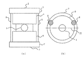
図5に本実施例の超電導磁石装置の第4の実施例の正面図と中央断面図を示す。図6には比較のため第1の実施例の場合の同じ図を示す。本実施例においては、上下の冷却容器2,3の構造および配置は第1の実施例と同様であるが、連結管8の配置が異なる。図5(b)の本実施例の中央断面図に示す如く、本実施例では、左右の2本の連結管8を、均一磁場領域1の中心を通る左右方向の中心線22に対し、第1の実施例よりも後方に配置したものである。その結果、均一磁場領域1を基準にして、前方および左右の空間が開けることになり、第1の実施例に比べ左右方向(横方向)からの被検体へのアクセス性が向上する。
【0034】
図7に本発明の超電導磁石装置の第5の実施例の外観図を示す。本実施例は水平磁場方式の超電導磁石装置で、均一磁場領域1の左右に左側冷却容器30と右側冷却容器31とが対向して配置されている。各々の冷却容器30,31には均一磁場領域1に水平方向の均一磁場を生成する主コイルと漏洩磁場を低減するためのシールドコイルが内包されている。左側冷却容器30に内包される主コイルとシールドコイルとはほぼ同径に作られているため、左側冷却容器30の外周は小径の左側小径部32から成り、右側冷却容器31に内包される主コイルとシールドコイルとは、シールドコイルの直径が主コイルの直径より大きく作られているため、右側冷却容器31の外周は小径の右側小径部33と大径の右側大径部34とから成る。また、各々の冷却容器30,31には、被検体を挿入するための穴35,36が設けられている。
【0035】
超電導磁石装置を上記の如く構成したことにより、被検体にとっての開放性は均一磁場領域1の左側の方が少し良好となるが、均一磁場領域1の周辺の冷却容器30,31の外周は小径であるので、被検体の開放性および術者の被検体へのアクセス性は良好である。また、漏洩磁場のシールド効果については、大径のシールドコイルが内包されている右側の部分の方が良好である。本実施例の場合、右側冷却容器31にのみ大径部を設けたが、本発明ではこれに限定されず、この大径部は左側冷却容器30のみに設けても良く、両冷却容器に設けても良い。
【0036】
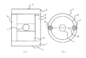
図8に本発明の超電導磁石装置の第6の実施例の外観図を示す。本実施例では磁場発生源の部分については第1の実施例とほぼ同じ構造であるが、その周囲に強磁性体から成る磁気シールドを施したものである。図8において、均一磁場領域1を挾んで上下方向に上側冷却容器2と下側冷却容器3が対向して配置されている。上側冷却容器2は上側主コイルを収納する上側小径部4と上側シールドコイルを収納する上側大径部5を有し、下側冷却容器3は下側主コイルを収納する下側小径部6と下側シールドコイルを収納する下側大径部7を有する。上側冷却容器2の上側および下側冷却容器3の下側には鉄などの強磁性体から成る円板状の上側シールド板40および下側シールド板41が配置され、両シールド板40,41の間は2本の鉄などの強磁性体から成る円柱状のヨーク42によって接続され、かつ支持されている。
【0037】
本実施例においても、上側主コイルと下側主コイルによって均一磁場領域1に均一磁場が生成され、上側シールドコイルと下側シールドコイルによって外部への漏洩磁場が低減される。本実施例の場合、上下の冷却容器2,3の外側に上下のシールド板40,41とヨーク42を配置したことにより、上下方向の磁束の帰路として上側シールド板40とヨーク42と下側シールド板41とから成る磁気回路を形成して、漏洩磁場の更なる低減を図るものである。
【0038】
本実施例は、漏洩磁場の抑制のため、主コイルとシールドコイルとを組み合わせるアクティブシールド方式と強磁性体から成る磁気回路を用いたパッシブシールド方式を併用したものであるが、前者のアクティブシールド方式としては、上記の第1の実施例のみに限定されず、第2〜第5の実施例を適用した場合にも組合せは可能であり、同様な効果を上げることができる。このようなパッシブシールド方式の併用は、漏洩磁場を大幅に低減したいときや、アクティブシールド方式のみでは漏洩磁場の低減が困難な場合に有効であり、高い磁場強度,開放性,低漏洩磁場が必要な用途に適用が可能である。
【0039】
【発明の効果】
以上説明した如く、本発明によれば、超電導磁石装置の冷却容器の外径について均一磁場領域からの遠近により外径差が設けられ、主コイルが収納される部分は小径に、シールドコイルが収納される部分は大径に構成される。その結果、大径シールドコイルの適用により漏洩磁場が大幅に低減されると共に、均一磁場領域に近い部分の冷却容器の直径は小径であるので、被検体にとっての開放性および術者にとってのアクセス性の高い磁気共鳴イメージング装置の提供が可能となる。本発明ガ特徴とする超電導磁石装置は上記の特徴を生かして、主にMRI装置に適用されるが、MRI装置以外にも単結晶引上げ装置などの均一な高磁場を必要とする用途に適用できる。
【図面の簡単な説明】
【図1】本発明の超電導磁石装置の第1の実施例の外観図。
【図2】本発明の超電導磁石装置の第1の実施例の断面図。
【図3】本発明の超電導磁石装置の第2の実施例の外観図。
【図4】本発明の超電導磁石装置の第3の実施例の外観図。
【図5】本発明の超電導磁石装置の第4の実施例の正面図と中央断面図。
【図6】本発明の超電導磁石装置の第1の実施例の正面図と中央断面図。
【図7】本発明の超電導磁石装置の第5の実施例の外観図。
【図8】本発明の超電導磁石装置の第6の実施例の外観図。
【符号の説明】
1 均一磁場領域(撮影領域)
2 上側冷却容器
3 下側冷却容器
4,20 上側小径部
5 上側大径部
6,21 下側小径部
7 下側大径部
8 連結管
9 上側磁場発生源
10 下側磁場発生源
11 上側主コイル
12 上側シールドコイル
13 下側主コイル
14 下側シールドコイル
15 超電導用冷媒(液体ヘリウム)
16 冷媒容器(液体ヘリウム容器)
17 真空容器
22 中心線
30 右側冷却容器
31 左側冷却容器
32 右側小径部
33 右側大径部
34 左側小径部
35,36 穴
40 上側シールド板
41 下側シールド板
42 ヨーク[0001]
BACKGROUND OF THE INVENTION
The present invention relates to a magnetic resonance imaging apparatus (hereinafter referred to as an MRI apparatus), and has a particularly wide opening to give a subject a sense of openness and facilitate access to the subject for an operator. The present invention relates to a magnetic resonance imaging apparatus having a superconducting magnet apparatus.
[0002]
[Prior art]
Currently, permanent magnets and superconducting magnets are used in apparatuses using a uniform high magnetic field such as MRI apparatuses. In recent years, MRI apparatuses and the like are required to have high image resolution, and superconducting magnets that can generate a high magnetic field tend to be frequently used.
[0003]
In addition, a cylindrical horizontal magnetic field type superconducting magnet device was originally used in the MRI apparatus, but in this method, a uniform magnetic field region is generated in the cylinder, so that the subject is left in the cylinder for a long time during the examination. As a result, this gives a sense of blockage to the subject, which is a problem. For this reason, in recent MRI apparatuses, those using open-type magnets are becoming mainstream except those using high-magnetic superconducting magnet apparatuses.
[0004]
An open-type magnet has a pair of magnetic field generation sources facing each other across a uniform magnetic field region, and since the periphery of the uniform magnetic field region is open, the openness for the subject is very good. is there. As an MRI apparatus using an open-type magnet, a vertical magnetic field system using a permanent magnet has been the mainstream, but recently, an apparatus using a normal conducting magnet apparatus or a superconducting magnet apparatus has been commercialized. Yes.
[0005]
As the open superconducting magnet device, there are a vertical magnetic field type and a horizontal magnetic field type. Many of the magnetic field generation sources of these open superconducting magnet devices can adopt an active shield system in order to suppress the leakage magnetic field. In this active shield type magnet, a pair of shield coils are arranged outside the center of the uniform magnetic field space of the pair of main coils that generate a uniform magnetic field, and a current in a direction opposite to that of the main coil is disposed in the shield coil. The leakage magnetic field around the magnet is suppressed by flowing the.
[0006]
As a first example of an open type active shield type superconducting magnet device, there is one disclosed in Japanese Patent Laid-Open No. 9-153408 (hereinafter referred to as well-known example 1). In the magnet of publicly known example 1, a main coil and a cancellation coil (corresponding to a shield coil) housed in a pair of cooling containers are arranged facing each other across a uniform magnetic field region. The outer diameter of the main coil and the outer diameter of the cancellation coil are almost the same size, and the outer diameter of the cooling container that houses them is uniform. In the magnet having such a structure, there is a problem that the entire apparatus becomes large in order to reduce the leakage magnetic field.
[0007]
As a second example of the open-type active shield superconducting magnet device, there is one disclosed in Japanese Patent Laid-Open No. 9-190913 (hereinafter referred to as well-known example 2). In the magnet of the known example 2, a passive shield type magnetic shield made of a disk-shaped ferromagnetic material, a cylindrical ferromagnetic material, a columnar ferromagnetic material, or the like is arranged around the magnet of the known example 1, and the main coil is used. The leakage magnetic field is suppressed by forming a return path of the generated magnetic flux. In the known example 2, the cancellation coil is usually omitted. However, when the cancellation coil is used, the outer diameter of the cancellation coil is equal to or less than the outer diameter of the main coil, and the main coil and the cancellation coil are accommodated. The outer diameter of the cooling container is uniform. In the magnet having such a structure, the magnetic shield is performed by combining the active shield method and the passive shield method, so that the leakage magnetic field can be greatly suppressed, but since the passive shield method is adopted, the magnet The problem of increased weight arises.
[0008]
As a third example of the open-type active shield superconducting magnet apparatus, there is one disclosed in US Pat. No. 5,448,214 (hereinafter referred to as “known example 3”). The magnet of the known example 3 is of the horizontal magnetic field type, and the outer diameter of the shield coil is larger than the outer diameter of the main coil, but both coils are housed in separate cooling containers. In the magnet having such a structure, there are problems that the number of cooling containers increases and the structure becomes complicated, and the total length becomes long, so that it is difficult to adopt the vertical magnetic field method.
[0009]
[Problems to be solved by the invention]
As described in the above prior art, in the conventional open superconducting magnet device, it is difficult to suppress the leakage magnetic field with a simple structure. That is, when the shield coil is used in the active shield system, the outer diameter of the shield coil must be increased in order to increase the effect of suppressing the leakage magnetic field. As a result, in the case of the known example 1, the cooling container is used. The outer diameter of the patient becomes large, and the feeling of opening for the subject is greatly impaired, making it difficult for the operator to access the subject. Further, in the case of the known example 3, since the number of cooling containers increases, there is a problem that the structure becomes complicated and the cost increases. Further, when a magnetic shield made of iron or the like is used in the passive shield method, there is a problem that the weight of the whole magnet becomes very heavy.
[0010]
For this reason, the present invention provides a super magnetic resonance imaging apparatus that is simple in structure, has little leakage magnetic field spread, gives the subject a great sense of openness, and allows the operator to easily access the subject. The purpose is to do.
[0011]
[Means for Solving the Problems]
In order to achieve the above object, at least one pair of magnetic field generation sources arranged facing each other across a uniform magnetic field region, a pair of cooling containers storing the magnetic field generation source, and the pair of cooling containers connected to each other. In the magnetic resonance imaging apparatus comprising the two connecting tubes, each of the magnetic field generation sources is coaxially arranged in the magnetic field direction of the uniform magnetic field, and has a main coil and a shield coil made of a material having superconducting characteristics. Thus, the outer diameters of the portions that house the shield coils of the pair of cooling containers are different from each other .
Alternatively, in at least one of the cooling containers, the outer diameter of the portion that houses the shield coil and the outer diameter of the portion that houses the main coil are different .
[0012]
In this configuration, in an open superconducting magnet apparatus in which a pair of magnetic field generation sources are arranged opposite to each other centering on a uniform magnetic field region, the main coil on the side where the outer diameter of the cooling container is close to the uniform magnetic field region is disposed. It is small and large at the part where the shield coil on the far side is arranged. As a result, since the outer diameter of the shield coil can be made larger than the outer diameter of the main coil, the effect of reducing the leakage magnetic field by the shield coil can be improved. In addition, since the outer diameter of the peripheral portion of the uniform magnetic field region of the cooling container is small, the openness of the subject and the operator's accessibility to the subject are good and do not deteriorate compared to the conventional one.
[0013]
Also, this configuration can be applied as an open vertical magnetic field superconducting magnet device with the uniform magnetic field direction as the vertical direction, or as an open horizontal magnetic field method superconducting magnet device with the uniform magnetic field direction as the horizontal direction. Is possible. In either case, the effect of reducing the leakage magnetic field, the openness of the subject, and the operator's accessibility are ensured.
[0014]
Furthermore, in the superconducting magnet device of the present invention, the outer diameter of the portion accommodating the shield coil in both cooling containers is larger than the outer diameter of the portion accommodating the main coil. In this configuration, since the cooling vessel and the magnetic field generation source (main coil and shield coil) can be symmetrically shaped around the uniform magnetic field region, high magnetic field uniformity can be obtained, and electromagnetic field can be used as the magnetic field generation source. Benefits include easy balance of power.
[0015]
Furthermore, in the superconducting magnet device of the present invention, only in one cooling container, the outer diameter of the portion accommodating the shield coil is larger than the outer diameter of the portion accommodating the main coil. Regarding the outer periphery of the cooling container, changing the outer diameter between the part for storing the main coil and the part for storing the shield coil complicates the structure of the cooling container, which causes an increase in cost. Therefore, in this configuration, it is advantageous in cost because only one side needs to be a cooling container having a complicated structure, and the restriction of the leakage magnetic field on one side of the uniform magnetic field region is relaxed compared to the other side, etc. The configuration is suitable for.
[0016]
Further, in the superconducting magnet device of the present invention, the magnetic field direction of the uniform magnetic field is the vertical direction, and the surgeon has an outer diameter of a portion containing the shield coil of the lower cooling container smaller than an outer diameter of the portion containing the main coil. The outer diameter of the upper cooling container is made uniform by increasing the height of the outer cooling container. In this configuration, since the outer diameter of the upper cooling container is uniform, the upper side is not covered and the feeling of pressure on the subject is reduced. In addition, by setting the protrusion of the outer periphery of the portion of the lower cooling container that houses the shield coil to an extent that the surgeon can stand, the substantial outer diameter of the lower cooling container is determined by the size of the small diameter portion that houses the main coil. Therefore, the leakage magnetic field to the lower side of the apparatus can be reduced without changing the operator's access to the subject.
[0017]
Further, in the superconducting magnet device of the present invention, the magnetic field direction of the uniform magnetic field is the vertical direction, and the outer diameter of the portion containing the shield coil of the upper cooling vessel is made larger than the outer diameter of the portion containing the main coil, The outer diameter of the cooling container is made uniform. In this configuration, since the outer diameter of the shield coil of the upper magnetic field generation source can be increased, the leakage magnetic field to the upper side of the apparatus can be suppressed, and the influence of the magnetic field on the floor can be eliminated.
[0018]
In the superconducting magnet apparatus of the present invention, the pair of cooling containers are connected by a plurality of connecting pipes, and the position of the outermost part from the center of the uniform magnetic field region of the connecting pipes is the part in which the shield coil of the cooling container is stored This is almost the same as the position of the outer diameter. In this configuration, since the outer diameter of the magnet including the plurality of connecting pipes is substantially the same as the maximum diameter of the cooling container, there is no protruding portion at the outer diameter of the magnet, and the structure of the cooling container is simplified. Moreover, since the protrusions are reduced in terms of design, the feeling of opening of the entire apparatus is enhanced.
[0019]
The superconducting magnet device according to the present invention further comprises a disk-shaped shield plate made of a pair of ferromagnetic materials around a pair of cooling vessels and a columnar yoke made of a plurality of ferromagnetic materials connecting both shield plates. Arranged magnetic circuit. In this configuration, a passive shield type magnetic shield is formed around the magnetic field generation source housed in the cooling container as a return path of the magnetic flux generated in the uniform magnetic field region by the main coil. It is greatly reduced.
[0020]
DETAILED DESCRIPTION OF THE INVENTION
Embodiments of the present invention will be described below with reference to the accompanying drawings.
FIG. 1 shows an external view of a first embodiment of the superconducting magnet apparatus of the present invention. In FIG. 1, the vertical direction is the Z axis, the horizontal direction is the X axis, and the direction perpendicular to the paper surface is the Y axis. FIG. 2 shows a cross-sectional view of this embodiment. In FIG. 2, the left half is the XZ cross section, and the right half is the YZ cross section.
[0021]
In FIG. 1, the superconducting magnet apparatus according to the present embodiment has an
[0022]
As shown in FIG. 2, an upper magnetic field generation source 9 is included in the
[0023]
The main coils 11 and 13 and the shield coils 12 and 14 are immersed in the
[0024]
A uniform magnetic field (magnetic flux density B 0 ) in the vertical direction (Z-axis direction) is generated in the uniform
[0025]
In the illustrated example, each of the
[0026]
In order to improve the effect of reducing the leakage magnetic field by the shield coils 12, 14, the shield coils 12, 14 are made larger in diameter than the corresponding
[0027]
Further, in the present embodiment, the outer diameter of the portion for storing the
[0028]
With this configuration, the diameter of the portion of the
[0029]
In FIG. 1, the connecting
[0030]
FIG. 3 shows an external view of a second embodiment of the superconducting magnet apparatus of the present invention. In the present embodiment, the diameter of the
[0031]
In the present embodiment, the outer diameter of the
[0032]
FIG. 4 shows an external view of a third embodiment of the superconducting magnet apparatus of the present invention. In the present embodiment, the diameter of the portion of the
[0033]
FIG. 5 shows a front view and a central sectional view of a fourth embodiment of the superconducting magnet apparatus of the present embodiment. FIG. 6 shows the same diagram in the case of the first embodiment for comparison. In this embodiment, the structure and arrangement of the upper and
[0034]
FIG. 7 shows an external view of a fifth embodiment of the superconducting magnet apparatus of the present invention. The present embodiment is a horizontal magnetic field type superconducting magnet device, in which a
[0035]
By configuring the superconducting magnet apparatus as described above, the openness for the subject is slightly better on the left side of the uniform
[0036]
FIG. 8 shows an external view of a sixth embodiment of the superconducting magnet apparatus of the present invention. In this embodiment, the magnetic field generation source has the same structure as that of the first embodiment, but a magnetic shield made of a ferromagnetic material is provided around it. In FIG. 8, the
[0037]
Also in the present embodiment, a uniform magnetic field is generated in the uniform
[0038]
In this embodiment, in order to suppress the leakage magnetic field, the active shield system combining a main coil and a shield coil and the passive shield system using a magnetic circuit made of a ferromagnetic material are used together. However, the present invention is not limited only to the first embodiment described above, and combinations are possible even when the second to fifth embodiments are applied, and similar effects can be obtained. The combined use of such passive shield method is effective when it is desired to significantly reduce the leakage magnetic field or when it is difficult to reduce the leakage magnetic field only with the active shield method, and high magnetic field strength, openness, and low leakage magnetic field are required. It can be applied to various uses.
[0039]
【The invention's effect】
As described above, according to the present invention, the outer diameter of the cooling container of the superconducting magnet device is provided with an outer diameter difference depending on the distance from the uniform magnetic field region, the portion in which the main coil is accommodated has a small diameter, and the shield coil is accommodated. The part to be formed is configured to have a large diameter. As a result, the leakage magnetic field is greatly reduced by the application of the large-diameter shield coil, and the diameter of the cooling container in the portion close to the uniform magnetic field region is small, so that it is open to the subject and accessible to the operator. High magnetic resonance imaging apparatus can be provided. The superconducting magnet apparatus characterized by the present invention is mainly applied to an MRI apparatus by taking advantage of the above-mentioned characteristics, but can be applied to applications requiring a uniform high magnetic field such as a single crystal pulling apparatus in addition to the MRI apparatus. .
[Brief description of the drawings]
FIG. 1 is an external view of a first embodiment of a superconducting magnet apparatus according to the present invention.
FIG. 2 is a cross-sectional view of a first embodiment of the superconducting magnet apparatus of the present invention.
FIG. 3 is an external view of a second embodiment of the superconducting magnet apparatus according to the present invention.
FIG. 4 is an external view of a third embodiment of the superconducting magnet device of the present invention.
FIG. 5 is a front view and a central sectional view of a fourth embodiment of the superconducting magnet apparatus of the present invention.
FIG. 6 is a front view and a central sectional view of a first embodiment of the superconducting magnet apparatus of the present invention.
FIG. 7 is an external view of a fifth embodiment of the superconducting magnet device of the present invention.
FIG. 8 is an external view of a sixth embodiment of the superconducting magnet device of the present invention.
[Explanation of symbols]
1 Uniform magnetic field area (imaging area)
2
16 Refrigerant container (liquid helium container)
17
Claims (6)
Priority Applications (1)
| Application Number | Priority Date | Filing Date | Title |
|---|---|---|---|
| JP29013398A JP4023703B2 (en) | 1998-09-29 | 1998-09-29 | Magnetic resonance imaging system |
Applications Claiming Priority (1)
| Application Number | Priority Date | Filing Date | Title |
|---|---|---|---|
| JP29013398A JP4023703B2 (en) | 1998-09-29 | 1998-09-29 | Magnetic resonance imaging system |
Publications (3)
| Publication Number | Publication Date |
|---|---|
| JP2000102519A JP2000102519A (en) | 2000-04-11 |
| JP2000102519A5 JP2000102519A5 (en) | 2005-11-17 |
| JP4023703B2 true JP4023703B2 (en) | 2007-12-19 |
Family
ID=17752228
Family Applications (1)
| Application Number | Title | Priority Date | Filing Date |
|---|---|---|---|
| JP29013398A Expired - Fee Related JP4023703B2 (en) | 1998-09-29 | 1998-09-29 | Magnetic resonance imaging system |
Country Status (1)
| Country | Link |
|---|---|
| JP (1) | JP4023703B2 (en) |
Families Citing this family (2)
| Publication number | Priority date | Publication date | Assignee | Title |
|---|---|---|---|---|
| US6683456B1 (en) * | 2000-07-06 | 2004-01-27 | Koninklijke Philips Electronics, N.V. | MRI magnet with reduced fringe field |
| JP4266232B2 (en) * | 2006-11-17 | 2009-05-20 | 株式会社日立製作所 | Superconducting magnet apparatus and magnetic resonance imaging apparatus |
-
1998
- 1998-09-29 JP JP29013398A patent/JP4023703B2/en not_active Expired - Fee Related
Also Published As
| Publication number | Publication date |
|---|---|
| JP2000102519A (en) | 2000-04-11 |
Similar Documents
| Publication | Publication Date | Title |
|---|---|---|
| JP3731231B2 (en) | Superconducting magnet device | |
| JP3654463B2 (en) | Magnetic resonance imaging system | |
| US5936498A (en) | Superconducting magnet apparatus and magnetic resonance imaging system using the same | |
| JP3711659B2 (en) | Open magnetic resonance imaging magnet | |
| EP0770882B1 (en) | Open MRI superconductive magnet with cryogenic-fluid cooling | |
| JP2001224571A (en) | Open type superconductive magnetic and magnetic resonance imaging instrument using it | |
| US6664876B2 (en) | Superconducting magnet and magnetic resonance imaging apparatus using the same | |
| JP3824412B2 (en) | Superconducting magnet device for crystal pulling device | |
| JP4023703B2 (en) | Magnetic resonance imaging system | |
| JPH0219430B2 (en) | ||
| JP2002065631A (en) | Magnet device and magnetic resonance imaging apparatus using the same | |
| JP4065747B2 (en) | Superconducting magnet and magnetic resonance imaging apparatus using the same | |
| US6667676B2 (en) | Superconducting magnet and magnetic resonance imaging apparatus using the same | |
| JP3747981B2 (en) | Magnetic resonance imaging system | |
| JP2002017705A (en) | Magnetic resonance imaging device | |
| JP3856086B2 (en) | Magnetic resonance imaging system | |
| JPH09276246A (en) | Superconducting magnet device | |
| JP4565721B2 (en) | Superconducting magnet device and MRI device | |
| JP2803306B2 (en) | Magnet device for MRI | |
| JPH0442977A (en) | Superconducting magnet device | |
| JP2006326177A (en) | Superconductive magnet device for mri | |
| JP2005324036A (en) | Superconductive magnet and magnetic resonance imaging apparatus | |
| JP2006095022A (en) | Super-conductive magnet apparatus and magnetic resonance imaging apparatus using the same | |
| JPH05291035A (en) | Superconducting magnetic device | |
| JPH04199703A (en) | Magnet apparatus for imaging diagnostic equipment of nuclear magnetic resonance type |
Legal Events
| Date | Code | Title | Description |
|---|---|---|---|
| A521 | Written amendment |
Free format text: JAPANESE INTERMEDIATE CODE: A523 Effective date: 20050921 |
|
| A621 | Written request for application examination |
Free format text: JAPANESE INTERMEDIATE CODE: A621 Effective date: 20050921 |
|
| A131 | Notification of reasons for refusal |
Free format text: JAPANESE INTERMEDIATE CODE: A131 Effective date: 20070702 |
|
| A521 | Written amendment |
Free format text: JAPANESE INTERMEDIATE CODE: A523 Effective date: 20070824 |
|
| TRDD | Decision of grant or rejection written | ||
| A01 | Written decision to grant a patent or to grant a registration (utility model) |
Free format text: JAPANESE INTERMEDIATE CODE: A01 Effective date: 20070926 |
|
| A61 | First payment of annual fees (during grant procedure) |
Free format text: JAPANESE INTERMEDIATE CODE: A61 Effective date: 20070928 |
|
| R150 | Certificate of patent or registration of utility model |
Free format text: JAPANESE INTERMEDIATE CODE: R150 |
|
| FPAY | Renewal fee payment (event date is renewal date of database) |
Free format text: PAYMENT UNTIL: 20101012 Year of fee payment: 3 |
|
| FPAY | Renewal fee payment (event date is renewal date of database) |
Free format text: PAYMENT UNTIL: 20101012 Year of fee payment: 3 |
|
| FPAY | Renewal fee payment (event date is renewal date of database) |
Free format text: PAYMENT UNTIL: 20111012 Year of fee payment: 4 |
|
| FPAY | Renewal fee payment (event date is renewal date of database) |
Free format text: PAYMENT UNTIL: 20111012 Year of fee payment: 4 |
|
| FPAY | Renewal fee payment (event date is renewal date of database) |
Free format text: PAYMENT UNTIL: 20121012 Year of fee payment: 5 |
|
| FPAY | Renewal fee payment (event date is renewal date of database) |
Free format text: PAYMENT UNTIL: 20121012 Year of fee payment: 5 |
|
| FPAY | Renewal fee payment (event date is renewal date of database) |
Free format text: PAYMENT UNTIL: 20131012 Year of fee payment: 6 |
|
| LAPS | Cancellation because of no payment of annual fees |