JP4021855B2 - Floor joint device - Google Patents
Floor joint device Download PDFInfo
- Publication number
- JP4021855B2 JP4021855B2 JP2004019963A JP2004019963A JP4021855B2 JP 4021855 B2 JP4021855 B2 JP 4021855B2 JP 2004019963 A JP2004019963 A JP 2004019963A JP 2004019963 A JP2004019963 A JP 2004019963A JP 4021855 B2 JP4021855 B2 JP 4021855B2
- Authority
- JP
- Japan
- Prior art keywords
- joint
- joint plate
- floor
- support
- plate
- Prior art date
- Legal status (The legal status is an assumption and is not a legal conclusion. Google has not performed a legal analysis and makes no representation as to the accuracy of the status listed.)
- Expired - Lifetime
Links
- 239000004570 mortar (masonry) Substances 0.000 claims description 10
- 230000000694 effects Effects 0.000 description 5
- 239000004576 sand Substances 0.000 description 4
- 230000008531 maintenance mechanism Effects 0.000 description 3
- 239000000463 material Substances 0.000 description 2
- 230000007246 mechanism Effects 0.000 description 2
- 230000002787 reinforcement Effects 0.000 description 2
- 230000003014 reinforcing effect Effects 0.000 description 2
- 239000002537 cosmetic Substances 0.000 description 1
- 238000009408 flooring Methods 0.000 description 1
- 238000004519 manufacturing process Methods 0.000 description 1
- 239000007769 metal material Substances 0.000 description 1
- 239000012779 reinforcing material Substances 0.000 description 1
- 229910001220 stainless steel Inorganic materials 0.000 description 1
- 239000010935 stainless steel Substances 0.000 description 1
- 238000003466 welding Methods 0.000 description 1
Images


Landscapes
- Building Environments (AREA)
Description
本発明は目地部を介して設けられた左右の躯体や建物の床目地部を覆う床用目地装置に関する。 The present invention relates to a floor joint device that covers left and right housings and floor joint portions of a building provided through joint portions.
従来、目地部側の床面に反目地部側が傾斜面に形成された凹部と、この凹部に支持された目地部が狭くなると床面上に乗り上げる目地部を覆う目地プレートとを備える床用目地装置は、目地プレートを浅皿状の目地プレート本体内にモルタルやコンクリートを充填し、上部に化粧タイル等を設置しているため、目地プレートは重く、地震等で凹部上をスライド移動する場合に大きな抵抗となり、スムーズに移動させることができないという欠点があった。
また、目地プレート上を車両等が走行する場合には十分な強度が得られないという欠点があった。
Further, there is a drawback that sufficient strength cannot be obtained when a vehicle or the like travels on the joint plate.
本発明は以上のような従来の欠点に鑑み、重い目地プレートでも地震時等にスムーズにスライド移動することができるとともに、砂等が目地プレートの下部に侵入しても、該砂等が目地プレートのスライド移動のじゃまになるのを効率よく阻止することができる床用目地装置を提供することを目的としている。 In view of the conventional drawbacks as described above, the present invention can smoothly slide even a heavy joint plate during an earthquake or the like, and even if sand or the like enters the lower portion of the joint plate, An object of the present invention is to provide a floor joint device that can efficiently prevent the sliding movement of the floor.
また、本発明は目地プレート上を車両が走行しても十分な強度が得られる床用目地装置を提供することを目的としている。 Another object of the present invention is to provide a floor joint device capable of obtaining sufficient strength even when a vehicle travels on the joint plate.
本発明の前記ならびにそのほかの目的と新規な特徴は次の説明を添付図面と照らし合わせて読むと、より完全に明らかになるであろう。
ただし、図面はもっぱら解説のためのものであって、本発明の技術的範囲を限定するものではない。
The above and other objects and novel features of the present invention will become more fully apparent when the following description is read in conjunction with the accompanying drawings.
However, the drawings are for explanation only and do not limit the technical scope of the present invention.
上記目的を達成するために、本発明は目地部側の床面に反目地部側が傾斜面に形成された凹部と、この凹部に支持され目地部が狭くなると床面上に乗り上げる目地部を覆う目地プレートとを備える床用目地装置において、前記凹部に固定された前記目地プレートをスムーズにスライド移動できるように支持する、該目地プレートの移動方向と平行あるいは所定の傾斜となるように所定間隔に配置された複数個の支持バー、この複数個の支持バーの上部を除く両端部に底面が平坦となるように固定されたアングル状の固定バー、前記複数個の支持バーの上端部を除く部位の前記凹部内を覆うモルタルあるいはコンクリートとからなる目地プレート支持体を設けけて床用目地装置を構成している。 In order to achieve the above-described object, the present invention covers a recess formed on the floor surface on the joint portion side on the inclined surface on the side opposite to the joint portion, and a joint portion that is supported by the recess and rides on the floor surface when the joint portion becomes narrower. In a floor joint device including a joint plate, the joint plate fixed to the concave portion is supported so that the joint plate can be smoothly slid. The joint plate is parallel to the moving direction of the joint plate or at a predetermined inclination. A plurality of support bars arranged, an angle-shaped fixing bar fixed so that the bottom surface is flat at both ends excluding the upper portions of the plurality of support bars, and a portion excluding the upper ends of the plurality of support bars The floor joint device is configured by providing a joint plate support made of mortar or concrete covering the inside of the recess.
以上の説明から明らかなように、本発明にあっては次に列挙する効果が得られる。 As is clear from the above description, the present invention has the following effects.
(1)目地部側の床面に反目地部側が傾斜面に形成された凹部と、この凹部に支持され目地部が狭くなると床面上に乗り上げる目地部を覆う目地プレートとを備える床用目地装置において、前記凹部に固定された前記目地プレートをスムーズにスライド移動できるように支持する、該目地プレートの移動方向と平行あるいは所定の傾斜となるように所定間隔に配置された複数個の支持バー、この複数個の支持バーの上部を除く両端部に底面が平坦となるように固定されたアングル状の固定バー、前記複数個の支持バーの上端部を除く部位の前記凹部内を覆うモルタルあるいはコンクリートとからなる目地プレート支持体を設けているので、目地プレートのスライド移動は目地プレート支持体の複数個の支持バー上をスライド移動させることができる。
したがって、目地プレートのスライド移動時の抵抗が著しく低減でき、スムーズにスライド移動させることができる。
(1) A floor joint comprising a recess formed on the floor surface on the joint section side with an inclined surface on the side opposite to the joint section, and a joint plate that covers the joint section that is supported by the recess and rides on the floor surface when the joint section becomes narrow. In the apparatus, a plurality of support bars arranged so as to be parallel to a moving direction of the joint plate or at a predetermined inclination so as to support the joint plate fixed to the recess so as to be smoothly slidable. , An angle-shaped fixing bar fixed so that the bottom surface is flat at both ends except for the upper portions of the plurality of support bars, a mortar that covers the recesses in portions other than the upper ends of the plurality of support bars, or Since the joint plate support made of concrete is provided, the slide movement of the joint plate can be slid on the plurality of support bars of the joint plate support. Kill.
Therefore, the resistance during sliding movement of the joint plate can be remarkably reduced, and the sliding movement can be performed smoothly.
(2)前記(1)によって、複数個の支持バーの上端部を除く部位の凹部内をモルタルあるいはコンクリートで覆っているので、複数個の支持バーの上端部間に隙間が形成され、該隙間に砂等を侵入させることができる。
したがって、目地プレートの下部に侵入した砂等によって、目地プレートのスライド移動がスムーズにならなくなるのを効率よく阻止することができる。
(2) According to the above (1), since the concave portions of the portions excluding the upper ends of the plurality of support bars are covered with mortar or concrete, a gap is formed between the upper ends of the plurality of support bars. Sand and the like can be invaded.
Therefore, it is possible to efficiently prevent the sliding movement of the joint plate from becoming smooth due to sand or the like entering the lower portion of the joint plate.
(3)前記(2)によって、複数個の支持バーの隙間に侵入した砂等は両端部が閉じられていないので、簡単な作業で楽に排出させることができる。 (3) According to the above (2), since sand and the like that have entered the gaps between the plurality of support bars are not closed at both ends, they can be easily discharged by a simple operation.
以下、図面に示す本発明を実施するための最良の形態により、本発明を詳細に説明する。 Hereinafter, the present invention will be described in detail with reference to the best mode for carrying out the invention shown in the drawings.
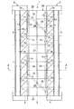
図1ないし図8に示す本発明を実施するための最良の第1の形態において、1は目地部2を介して設けられた左右の躯体3、3間を覆う本発明の床用目地装置で、この床用目地装置1は前記左右の躯体3、3の目地部2側の床躯体3a、3aに形成された左右の凹部4、4と、この左右の凹部4、4の反目地部側の端部に複数本のビス5等によって固定されたガイドパネル支持部材6、6、このガイドパネル支持部材6、6の上部に支持され複数本のビス7等によって固定されたほぼ45度以下の角度の傾斜面8を有するガイドパネル9、9とからなる左右の目地プレートガイド部材10、10と、この左右の目地プレートガイド部材10、10が取付けられた部位を除く前記凹部4、4に所定間隔に固定された左右方向にほぼ45度の傾斜で上端部が前記ガイドパネル9、9と同一あるいはわずかに高い位置となるように配置された複数個の支持バー11、11、この複数個の支持バー11、11の両端部の上部をのぞく部位に溶接あるいはビス等によって固定された凹部4、4の躯体3、3に複数本のビス12等よって固定される固定バー13、13、前記複数個の支持バー11の上端部を除く部位の前記凹部4、4内を覆うモルタルあるいはコンクリート14、14からなる左右の目地プレート支持体15、15と、前記左右の目地プレートガイド部材10、10を除く前記左右の目地プレート支持体15、15に両端部が左右方向にスライド移動可能に支持される目地プレート16と、この目地プレート16の上部両端部にヒンジ部材17、17を介して先端部が上下方向に回動可能に取付けられた端部カバープレート18、18と、前記目地プレート16の中央部を常時前記目地部2の中央部に位置させる目地プレート中央維持機構19とで構成されている。
In the first preferred embodiment for carrying out the present invention shown in FIGS. 1 to 8,
前記目地プレート16は図6に示すように、ステンレス材等の金属材で浅皿状に形成された目地プレート本体20と、この目地プレート本体20内に上部が該目地プレート本体20の上部よりも下部に位置するように設けられた、所定間隔で左右方向に配置された複数個の補強バー21と、この複数個の補強バー21を覆うように前記目地プレート本体20内に充填されたモルタルあるいはコンクリート22と、このモルタルあるいはコンクリート22の上部に、必要に応じて設置される化粧パネル等の化粧床材23とで構成されている。
As shown in FIG. 6, the
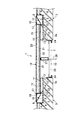
前記目地プレート中央維持機構19は図2および図3に示すように、前記左右の目地部側の躯体3、3にほぼ水平方向に固定された一対のガイドレール24、24と、この一対のガイドレール24、24にほぼ45度の傾斜状態でスライド移動可能に取付けられた支持アーム25と、この支持アーム25の中央部に上下方向にスライド移動可能に支持された上端部が、前記目地プレート16のほぼ中央部に取付けられたスライド軸26と、このスライド軸26に取付けられた前記支持アーム25で前記目地プレート16を支持できるように介装された支持部材27とで構成されている。
As shown in FIGS. 2 and 3, the joint plate
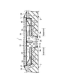
上記構成の床用目地装置1は地震等によって目地部2が広くなるように左右の躯体3、3が揺れ動いた場合には、図7に示すように目地プレート16の中央部が目地部2の中央部に位置するように目地プレート中央維持機構19で維持させる。
この時、目地プレート16の両端部は左右の目地プレート支持体15、15の複数個の支持バー11、11上をスライド移動するため、該スライド移動時の抵抗が小さく、スムーズにスライド移動させることができる。
When the left and
At this time, both end portions of the
目地部2が狭くなるように左右の躯体3、3が揺れ動いた場合には、図8に示すように目地プレート16は目地プレート中央維持機構19で目地部2の中央部に目地プレート16の中央部が位置するように維持されるとともに、両端部は左右の目地プレートガイド部材10、10のガイドパネル9、9の傾斜面8、8に沿って上方へスライド移動し、左右の躯体3、3の床躯体3a、3a上へ乗り上げて、その揺れ動きを吸収する。
なお、地震等の揺れ動きが停止すると、元の状態に自動的に戻る。
[発明を実施するための異なる形態]
When the left and
When the shaking motion such as an earthquake stops, it automatically returns to the original state.
[Different forms for carrying out the invention]
次に、図9ないし図19に示す本発明を実施するための異なる形態につき説明する。なお、これらの本発明を実施するための異なる形態の説明に当って、前記本発明を実施するための最良の第1の形態と同一構成部分には同一符号を付して重複する説明を省略する。 Next, different modes for carrying out the present invention shown in FIGS. 9 to 19 will be described. In the description of these different modes for carrying out the present invention, the same components as those in the best mode for carrying out the present invention are designated by the same reference numerals and redundant description is omitted. To do.
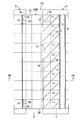
図9ないし図11に示す本発明を実施するための第2の形態において、前記本発明を実施するための最良の第1の形態と主に異なる点は、複数個の支持バー11、11を左右方向に並列配置した左右の目地プレート支持体15A、15Aを用いた点で、このような目地プレート支持体15A、15Aを用いて構成した床用目地装置1Aにしても、前記本発明を実施するための最良の第1の形態と同様な作用効果が得られる。
The second embodiment for carrying out the present invention shown in FIG. 9 to FIG. 11 is mainly different from the first embodiment for carrying out the present invention in that a plurality of
図12ないし図16に示す本発明を実施するための第3の形態において、前記本発明を実施するための最良の第1の形態と主に異なる点は、凹部4、4の躯体3、3に複数本のビス28等によって固定することができるアングル状の複数個の支持バー11A、11Aを使用した左右の目地プレート支持体15B、15Bを用いるとともに、目地プレート本体20内に格子状の補強材29を使用した目地プレート16Aを用いた点で、このような左右の目地プレート支持体15B、15Bや目地プレート16Aを用いた床用目地装置1Bにしても、前記本発明を実施するための最良の第1の形態と同様な作用効果が得られる。
The third embodiment for carrying out the present invention shown in FIGS. 12 to 16 mainly differs from the best first embodiment for carrying out the present invention in that the
図17ないし図19に示す本発明を実施するための第4の形態において、前記本発明を実施するための最良の第1の形態と主に異なる点は、一方の目地部側の躯体3に目地プレート16Bの後端部を支持する支持凹部30を形成し、該支持凹部30に目地プレート16Bの後端部の両側部寄りの底面部位に形成された係止凹部31、31に、該目地プレート16Bの先端部が上下方向に回動可能に支持するクサビ状の支持ピン32,32を設けた点で、このよう構成した床用目地装置1Cにしても、前記本発明を実施するための最良の第1の形態と同様な作用効果が得られる。
The fourth embodiment for carrying out the present invention shown in FIGS. 17 to 19 is mainly different from the best first embodiment for carrying out the present invention in the
なお、前記本発明を実施するための各形態では左右の躯体3、3間の目地部2を覆う床用目地装置について説明したが、本発明はこれに限らず、左右の建物の目地部の床躯体間を覆うように設置しても同様な作用効果が得られる。
In addition, although each form for implementing the said invention demonstrated the joint device for floors which covers the
本発明は床用目地装置を製造する産業および、該床用目地装置を設置する産業で利用される。 INDUSTRIAL APPLICABILITY The present invention is used in an industry for manufacturing a floor joint device and an industry for installing the floor joint device.
1、1A、1B、1C:床用目地装置、
2:目地部、 3:躯体、
4:凹部、 5:ビス、
6:ガイドパネル支持体、 7:ビス、
8:傾斜面、 9:ガイドパネル、
10:目地プレートガイド部材、 11、11A:支持バー、
12:ビス、 13:固定バー、
14:モルタルあるいはコンクリート、
15、15A、15B:目地プレート支持体、
16、16A、16B:目地プレート、 17:ヒンジ部材、
18:端部カバープレート、
19:目地プレート中央維持機構、
20:目地プレート本体、 21:補強バー、
22:モルタルあるいはコンクリート、
23:化粧床材、 24:ガイドレール、
25:支持アーム、 26:スライド軸、
27:支持部材、 28:ビス、
29:補強材、 30:支持凹部、
31:係止凹部、 32:支持ピン。
1, 1A, 1B, 1C: floor joint device,
2: joint part, 3: housing
4: Recess, 5: Screw,
6: Guide panel support, 7: Screw,
8: Inclined surface, 9: Guide panel,
10: Joint
12: Screw, 13: Fixing bar,
14: Mortar or concrete,
15, 15A, 15B: joint plate support,
16, 16A, 16B: joint plate, 17: hinge member,
18: end cover plate,
19: Joint plate center maintenance mechanism,
20: Joint plate body, 21: Reinforcement bar,
22: Mortar or concrete,
23: Cosmetic flooring, 24: Guide rail,
25: Support arm, 26: Slide shaft,
27: Support member, 28: Screw,
29: Reinforcing material, 30: Support recess,
31: Locking recess, 32: Support pin.
Claims (1)
Priority Applications (1)
| Application Number | Priority Date | Filing Date | Title |
|---|---|---|---|
| JP2004019963A JP4021855B2 (en) | 2004-01-28 | 2004-01-28 | Floor joint device |
Applications Claiming Priority (1)
| Application Number | Priority Date | Filing Date | Title |
|---|---|---|---|
| JP2004019963A JP4021855B2 (en) | 2004-01-28 | 2004-01-28 | Floor joint device |
Publications (2)
| Publication Number | Publication Date |
|---|---|
| JP2005213814A JP2005213814A (en) | 2005-08-11 |
| JP4021855B2 true JP4021855B2 (en) | 2007-12-12 |
Family
ID=34904032
Family Applications (1)
| Application Number | Title | Priority Date | Filing Date |
|---|---|---|---|
| JP2004019963A Expired - Lifetime JP4021855B2 (en) | 2004-01-28 | 2004-01-28 | Floor joint device |
Country Status (1)
| Country | Link |
|---|---|
| JP (1) | JP4021855B2 (en) |
Families Citing this family (2)
| Publication number | Priority date | Publication date | Assignee | Title |
|---|---|---|---|---|
| JP5188890B2 (en) * | 2008-06-25 | 2013-04-24 | ドーエイ外装有限会社 | Floor joint device |
| JP7489107B2 (en) | 2021-03-18 | 2024-05-23 | 株式会社エービーシー商会 | Floor expansion joint |
-
2004
- 2004-01-28 JP JP2004019963A patent/JP4021855B2/en not_active Expired - Lifetime
Also Published As
| Publication number | Publication date |
|---|---|
| JP2005213814A (en) | 2005-08-11 |
Similar Documents
| Publication | Publication Date | Title |
|---|---|---|
| JP6359727B1 (en) | Floor joint device | |
| JP2007327299A (en) | Joint device for floor | |
| JP4467476B2 (en) | Floor joint device | |
| JP4021855B2 (en) | Floor joint device | |
| JP3583698B2 (en) | Crosswalk | |
| JP2003074127A (en) | Floor joint device | |
| JP4755962B2 (en) | Floor joint device | |
| JP3445218B2 (en) | Floor joint equipment | |
| JP3797610B2 (en) | Cross-joint floor joint equipment | |
| JP6417435B2 (en) | Floor joint device and joint plate | |
| JP5188890B2 (en) | Floor joint device | |
| KR20060090953A (en) | Gallery window | |
| JP3662181B2 (en) | Floor joint device | |
| JP3691778B2 (en) | Floor joint device | |
| JP4633677B2 (en) | Floor joint device | |
| JP7081779B2 (en) | Floor joint device | |
| JP3122356B2 (en) | Floor joint equipment | |
| JP3382570B2 (en) | Fire wall | |
| JP3583695B2 (en) | Crosswalk | |
| JP3820187B2 (en) | Cross-joint floor joint equipment | |
| JP7045078B2 (en) | Floor joint device | |
| JP6204425B2 (en) | Joint device | |
| JP3974104B2 (en) | Floor joint device | |
| JP3442309B2 (en) | Joint cover device | |
| JP4475588B2 (en) | Ceiling joint device |
Legal Events
| Date | Code | Title | Description |
|---|---|---|---|
| A621 | Written request for application examination |
Free format text: JAPANESE INTERMEDIATE CODE: A621 Effective date: 20050830 |
|
| A977 | Report on retrieval |
Free format text: JAPANESE INTERMEDIATE CODE: A971007 Effective date: 20070524 |
|
| A131 | Notification of reasons for refusal |
Free format text: JAPANESE INTERMEDIATE CODE: A131 Effective date: 20070605 |
|
| A521 | Request for written amendment filed |
Free format text: JAPANESE INTERMEDIATE CODE: A523 Effective date: 20070806 |
|
| TRDD | Decision of grant or rejection written | ||
| A01 | Written decision to grant a patent or to grant a registration (utility model) |
Free format text: JAPANESE INTERMEDIATE CODE: A01 Effective date: 20070918 |
|
| A61 | First payment of annual fees (during grant procedure) |
Free format text: JAPANESE INTERMEDIATE CODE: A61 Effective date: 20070927 |
|
| FPAY | Renewal fee payment (event date is renewal date of database) |
Free format text: PAYMENT UNTIL: 20101005 Year of fee payment: 3 |
|
| R150 | Certificate of patent or registration of utility model |
Ref document number: 4021855 Country of ref document: JP Free format text: JAPANESE INTERMEDIATE CODE: R150 |
|
| FPAY | Renewal fee payment (event date is renewal date of database) |
Free format text: PAYMENT UNTIL: 20101005 Year of fee payment: 3 |
|
| FPAY | Renewal fee payment (event date is renewal date of database) |
Free format text: PAYMENT UNTIL: 20131005 Year of fee payment: 6 |
|
| R250 | Receipt of annual fees |
Free format text: JAPANESE INTERMEDIATE CODE: R250 |
|
| R250 | Receipt of annual fees |
Free format text: JAPANESE INTERMEDIATE CODE: R250 |
|
| R250 | Receipt of annual fees |
Free format text: JAPANESE INTERMEDIATE CODE: R250 |
|
| R250 | Receipt of annual fees |
Free format text: JAPANESE INTERMEDIATE CODE: R250 |
|
| R250 | Receipt of annual fees |
Free format text: JAPANESE INTERMEDIATE CODE: R250 |
|
| EXPY | Cancellation because of completion of term |