JP4021716B2 - Camera with strobe adjustment function - Google Patents
Camera with strobe adjustment function Download PDFInfo
- Publication number
- JP4021716B2 JP4021716B2 JP2002178255A JP2002178255A JP4021716B2 JP 4021716 B2 JP4021716 B2 JP 4021716B2 JP 2002178255 A JP2002178255 A JP 2002178255A JP 2002178255 A JP2002178255 A JP 2002178255A JP 4021716 B2 JP4021716 B2 JP 4021716B2
- Authority
- JP
- Japan
- Prior art keywords
- photo
- strobe
- camera
- pixels
- exposure
- Prior art date
- Legal status (The legal status is an assumption and is not a legal conclusion. Google has not performed a legal analysis and makes no representation as to the accuracy of the status listed.)
- Expired - Fee Related
Links
- 229920006395 saturated elastomer Polymers 0.000 claims description 38
- 238000000034 method Methods 0.000 claims description 16
- 240000007320 Pinus strobus Species 0.000 description 67
- 238000012360 testing method Methods 0.000 description 4
- 238000012986 modification Methods 0.000 description 3
- 230000004048 modification Effects 0.000 description 3
- 238000007796 conventional method Methods 0.000 description 2
- 238000010586 diagram Methods 0.000 description 2
- 238000010187 selection method Methods 0.000 description 2
- 230000003321 amplification Effects 0.000 description 1
- 238000013459 approach Methods 0.000 description 1
- 230000003247 decreasing effect Effects 0.000 description 1
- 230000000694 effects Effects 0.000 description 1
- 230000004313 glare Effects 0.000 description 1
- 238000005286 illumination Methods 0.000 description 1
- 238000003199 nucleic acid amplification method Methods 0.000 description 1
- 238000005070 sampling Methods 0.000 description 1
- 238000009738 saturating Methods 0.000 description 1
Images


Classifications
-
- H—ELECTRICITY
- H04—ELECTRIC COMMUNICATION TECHNIQUE
- H04N—PICTORIAL COMMUNICATION, e.g. TELEVISION
- H04N23/00—Cameras or camera modules comprising electronic image sensors; Control thereof
- H04N23/70—Circuitry for compensating brightness variation in the scene
- H04N23/74—Circuitry for compensating brightness variation in the scene by influencing the scene brightness using illuminating means
-
- G—PHYSICS
- G03—PHOTOGRAPHY; CINEMATOGRAPHY; ANALOGOUS TECHNIQUES USING WAVES OTHER THAN OPTICAL WAVES; ELECTROGRAPHY; HOLOGRAPHY
- G03B—APPARATUS OR ARRANGEMENTS FOR TAKING PHOTOGRAPHS OR FOR PROJECTING OR VIEWING THEM; APPARATUS OR ARRANGEMENTS EMPLOYING ANALOGOUS TECHNIQUES USING WAVES OTHER THAN OPTICAL WAVES; ACCESSORIES THEREFOR
- G03B15/00—Special procedures for taking photographs; Apparatus therefor
- G03B15/02—Illuminating scene
- G03B15/03—Combinations of cameras with lighting apparatus; Flash units
- G03B15/05—Combinations of cameras with electronic flash apparatus; Electronic flash units
-
- H—ELECTRICITY
- H04—ELECTRIC COMMUNICATION TECHNIQUE
- H04N—PICTORIAL COMMUNICATION, e.g. TELEVISION
- H04N23/00—Cameras or camera modules comprising electronic image sensors; Control thereof
- H04N23/70—Circuitry for compensating brightness variation in the scene
- H04N23/71—Circuitry for evaluating the brightness variation
-
- G—PHYSICS
- G03—PHOTOGRAPHY; CINEMATOGRAPHY; ANALOGOUS TECHNIQUES USING WAVES OTHER THAN OPTICAL WAVES; ELECTROGRAPHY; HOLOGRAPHY
- G03B—APPARATUS OR ARRANGEMENTS FOR TAKING PHOTOGRAPHS OR FOR PROJECTING OR VIEWING THEM; APPARATUS OR ARRANGEMENTS EMPLOYING ANALOGOUS TECHNIQUES USING WAVES OTHER THAN OPTICAL WAVES; ACCESSORIES THEREFOR
- G03B2215/00—Special procedures for taking photographs; Apparatus therefor
- G03B2215/05—Combinations of cameras with electronic flash units
Landscapes
- Engineering & Computer Science (AREA)
- Multimedia (AREA)
- Signal Processing (AREA)
- Physics & Mathematics (AREA)
- General Physics & Mathematics (AREA)
- Studio Devices (AREA)
- Exposure Control For Cameras (AREA)
- Stroboscope Apparatuses (AREA)
Description
【0001】
【発明の属する技術分野】
本発明は、一般に、写真に関し、より具体的には、フラッシュまたはストロボを使用する写真に関する。
【0002】
【従来の技術】
カメラは、写真の露出を適切にする様々な技術を使用する。一般に、カメラは、選択されたカメラ設定を使用してシーンの1つまたは複数の試験的な写真を作成する。露出レベルを改善するために、そのような試験的な写真を解析し、シーンから捕捉する光の量ならびに露出を調整する方法を決定する。次に、カメラは、最終写真を撮影する前に、適正な露出が達成されるようにいくつかの設定のどれかを調整する。
【0003】
調整することができるカメラ設定には、シャッタ時間(機械式または電子式)、レンズ口径比、カメラ内の信号の電子増幅の設定(システム利得と呼ばれることがある)、シーンの周囲光を補うためにストロボをたくかどうかの設定、ストロボをたく場合にストロボにどれだけのエネルギーを供給するかどうかの設定がある。場合によっては、適正な露光を達成するために、カメラのユーザがいくつかまたはすべての設定を指定し、カメラに残りの設定を調整させることがある。
【0004】
行うべき調整を決定するために、カメラは、適正な露出の定義を想定し、カメラ内にはそれぞれ可能な調整が最終写真の露出にどのように影響するかの情報が組み込まれている。
【0005】
ストロボが使用される場合、ストロボに供給するエネルギーの適正な量を決定する方法が必要である。ストロボに供給するエネルギーが多いほど、ストロボが出す光が多くなり、その結果写真の露出が明るくなる。
【0006】
この発明において、写真は、カメラによって捕捉されるシーンの数値表現でよく、シーンの印刷表現である必要がない。
【0007】
適正なストロボ・エネルギーを決定する一般的な方法は、既知の量に設定されたストロボ・エネルギーで試験的な写真を撮影することである。得られた写真を調べ、その露光品質を評価する。調整が必要な場合は、ストロボ・エネルギーの新しい値を決定する。次に、計算したエネルギー値を使用して最終写真を撮影する。露光量が多すぎるために、試験的な写真のいくつかの領域が完全に露出されていることが分かったときは、最終写真に使用されるエネルギー・レベルを、試験的な写真に使用したストロボ・エネルギーから減らすことができる。領域が完全に露出されたという1つのしるしは、写真のその領域内の画素データが飽和されていることである。飽和することは、それらの画素を表すディジタル値が、カメラが示すことができる最高値であり、それらの画素に光を追加してもディジタル値が高くならないことを意味する。
【0008】
しかしながら、この方法は、シーンが、グレア反射などのきわめて明るい光の小さい領域あるいは照明設備やランプなどの自己発光光源を含むときには、良好な結果が得られないときがある。カメラは、きわめて明るい領域が、試験的な写真で使用されたストロボ・エネルギーの結果であると想定し、シーンの他の部分を適正に露出するのに必要なストロボ・エネルギーの量を実際よりも低く評価する場合がある。代替として、カメラは、明るい領域をシーン全体の十分な照明として解釈し、追加のストロボを必ずしも使用しないように選択することがあり、それにより写真が露出不足なることがある。いずれの場合も、写真は、適正に露出されない。
【0009】
【発明が解決しようとする課題】
撮影しようとするシーンが、小さくてきわめて明るい領域を含むときにストロボ・エネルギーを適正に設定する技術が必要である。
【0010】
【課題を解決するための手段】
カメラのストロボ・エネルギーを調整して露出を改善する。周囲光だけを使用したシーンの試験的な露出を得る。周囲光だけの試験的な写真で完全に露出または飽和されることが分かった画素は、最終写真に適切なストロボ・エネルギーの計算においてあらかじめ考慮される。
【0011】
【発明の実施の形態】
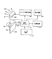
図1は、カメラのブロック図を示す。レンズ(101)は、シーン(図示せず)から光を収集する。収集された光は、センサ(103)上にシーンの像を形成するように方向変更される(102)。センサは、CCD素子、CMOSセンサなどのセンサアレイでよい。レンズの動作は、マイクロプロセッサ・システムを含む論理ユニット(110)からの制御信号(113)によって制御されることがある。同様に、センサの動作は、論理ユニット(110)からの制御信号(105)によって制御されることがある。画像情報信号(104)が、センサから論理ユニット(110)に流れる。
【0012】
フラッシュまたはストロボ(106)を利用して、シーンに追加の光(107)を提供することができる。ストロボは、ストロボ電子回路(108)によって操作され、ストロボ電子回路(108)は、論理ユニット(110)によって制御される。カメラは、画像データを表示することができる表示装置(109)を含むことができる。カメラは、画像データの記憶と呼び出しならびに他の装置(図示せず)とのデータ交換のための記憶装置(111)を含むことができる。カメラのユーザは、カメラの動作に影響を与えるように、様々な制御入力(112)を操作することができる。
【0013】
図2は、きわめて明るい光の小さい領域を含むシーンの写真を示す。このケースでは、点灯されたランプが写真に含まれている。この写真から、写真の作成に使用されたカメラが、写真を暗くしすぎる設定を使用したことは明らかである。露出に影響を及ぼすカメラ設定を変更するよりよい方法によって、写真を大幅に改善することができる。
【0014】
ディジタル・カメラ、またはフィルム・カメラ用の露出センサは、本質的に、撮影する写真ごとに数値表現を生成する。カメラは、「画素」または「ピクセル」と呼ばれる写真内の各場所ごとに、その場所におけるシーンの明るさを示す数値を記録する。この場合、得られるシーンの表現は、数の配列である。配列内の場所は、特定の画素すなわちシーン内の場所に対応し、各配列場所に記憶された数は、その場所におけるシーンの明るさを表す。
【0015】
また、カメラは、任意に、撮影しようとしているシーンの各画素位置における色に関する情報を記録することができる。本発明を説明するために、各画素の輝度についてのみ考察する。画素の輝度の高さは、色情報から計算することができる。例えば、多くのカメラは、画素の輝度に対する赤色波長、緑色波長および青色波長の光の寄与率を示す3つの成分を使用して画素の色を表す。画素の全輝度は、赤、緑、および青の寄与率の和として、重み付けされた和として、あるいは色情報の他の組合せとして計算されることがある。当該技術分野において、色情報から画素の輝度を計算する様々な方法が周知である。本発明が、各画素に関する輝度情報だけを記録するカメラと色情報も記録するカメラとに等しい機能を提供することは、当業者には容易に明らかになるであろう。
【0016】
写真の露出を解析する一般的な有用なツールは、露出ヒストグラムである。図3は、図2に示したシーンの露出ヒストグラムを示す。露出ヒストグラムは、カメラの露出範囲を様々な「ビン(bin)」(領域)に分割し、次に画像から各ビンに入る画素がいくつかあるかをカウントすることによって構成される。例えば、図2を生成するために使用されたカメラは、画素の輝度を0から1,023の値として表わすことができる。図3のヒストグラムは、この輝度範囲を64のビンに区分している。したがって、ビン0(301)は、画像内の0〜15の範囲の輝度値を有する画素の総数を収集する。ビン1(302)は、画像内の16から31の範囲の輝度値を有する画素の総数を収集する。これ以後のビンも同じパターンに従い、1,008から1,023の輝度値を有する画像画素の総数を収集するビン63(303)で終わる。
【0017】
ビン63(303)に入る輝度値を有する画素は、完全に露出または飽和されている。そのような画素の露出を高くしても、ビン内にある画素に影響はない。カメラは、1,023を超える輝度値を記録することができない。1,008以上の輝度値になるレベルよりも明るい画素は、常に、ビン63(303)に入る。そのような画素は、写真の露出が高くなっても応答しない。
【0018】
しかしながら、そのような画素の露出を低くする場合、それらの輝度値が低く扱われることがあり、そのうちのいくつかまたはすべての画素が、小さい番号のビンでカウントされることがある。
【0019】
一般に、最も小さい番号のビン内の画素の数を最少にし、また写真の飽和画素の数を最少にすることは、これらの両方の画素数が多いと写真情報の損失に結びつくことがあるため、望ましい。カメラは、一般に、写真の画素の大部分を代表的なシーンの平均輝度を表すビンに入れるようにストロボ・エネルギーを調整し、同時にさらに両端のビン内の画素の数を最少にするようにストロボ・エネルギーを調整しようとする。
【0020】
撮影しようとするシーンがきわめて明るい光の小さい領域を含むときは、従来のストロボ・エネルギー選択方法では写真の品質の低下に結びつくので、画像内の飽和画素の数を最少にすることが望ましい。図2の写真は、既知のストロボ・エネルギー設定で試験的に写真を撮影し、得られた画像の露出ヒストグラムを解析し、ストロボ・エネルギーの新しい値を計算し、次に最終写真を撮影する従来の方法によって撮影された。
【0021】
図4に、試験的な写真の露出ヒストグラムを示す。画像内の画素の大部分は、小さい番号のビンに入るが、ほぼビン2〜22(401)にも分散される。ビン63(402)に入る1,973の飽和画素がなければ、これは、適切に露出された写真を示す。カメラは、写真の品質を高めるために、飽和画素が過度のストロボ・エネルギーによるものであると仮定し、したがって図2の最終写真を撮影する前にストロボ・エネルギーを減少させた。
【0022】
試験的な写真が、CCD二次標本抽出による最終写真と異なる数の画素を有する場合があることに注意されたい。
【0023】
図3に、図2の画像の露出ヒストグラムを示す。得られた画像は、画素が、ヒストグラムのビン6とそれよりも小さい番号のビン(304)に入り、露出不足の写真を示すことが分かる。しかしながら、かなりの数の画像画素が、まだビン63(303)に入っており、ストロボ・エネルギーの低下によって画素の飽和がなくならなかったことを示す。
【0024】
このように、従来の方法によって露出不足の写真が得られた。
【0025】
ディジタル・コンピュータを使用してこの写真を処理して、露出を修正することができる。しかしながら、露出を改善するために必要な画像の修正は、一般に、画像内の目障りなノイズを明らかにしたり強調したりするため、この手法は、不十分なこともある。
【0026】
さらに良い解決策は、写真を撮影するときにカメラが写真を適正に露出する方法を見つけることである。
【0027】
本発明の実施例において、2つの試験的な写真が撮影され、1つは、ストロボを使用せずにシーンからの周囲光だけを使用して撮影され、1つは事前設定されたストロボ・エネルギー設定を使用して撮影される。この両方の試験的な写真に使用される露出設定は、露出時間、レンズ口径、システム・ゲインなど、最終画像にストロボが使用されたときに使用される設定と同じでよい。これらの設定は異なるものでもよく、その場合、正確な比較のために得られた露出ヒストグラムが調整されることがある。
【0028】
周囲光のみの写真の露出ヒストグラムに飽和画素があるか検査される。飽和画素が見つかった場合は、この試験的な写真にはストロボが使用されていないため、それら飽和画素は、試験的なストロボによるものではありえない。必然的に、飽和画素は、シーン自体内のきわめて明るい領域によるものでなければならない。したがって、そのような画素は、ストロボ・エネルギーの変化に対応せず、最終写真に使用するストロボ・エネルギーを計算するときあらかじめ考慮されても無視されてもよい。
【0029】
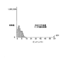
例えば、図5は、ストロボなしで撮影したときの図2に示したシーンの露出ヒストグラムを示す。この露出ヒストグラムは、一般に露出不足の画像を示すが、1,649の飽和画素(501)を有する。ストロボを使用しなかったので、これらの画素は、シーン内に含まれている光源によって飽和され、ストロボ・エネルギーの変化に対応しない。
【0030】
この結果が、次に、試験的なストロボで撮影された同じシーンの露出ヒストグラム(図3の情報)と組み合わされる。図4では、図5よりも324個だけ多い画素が飽和されている。本発明では、カメラは、ストロボ出力をわずか324個の飽和画素を含む露出ヒストグラム(試験的なストロボの露出ヒストグラムの残りの部分と共に)に基づいて計算し、したがって最終写真を撮影する前に出力がほんのわずかに減少する。
【0031】
図6に、本発明による最終写真の露出ヒストグラムを示す。図3で飽和された画素と類似の割合の画素が飽和され(601)、シーンの露出ヒストグラムが、従来の方法によって撮影されるが、写真が全体として前よりも良い状態で露出されている。
【0032】
サンプルの実施形態は、ストロボ・エネルギーを計算する手順のステップの増やすが、カメラが写真を撮影するのに必要な時間は必ずしも増えないことがある。一般に、ストロボ・エネルギーに関連しない様々な理由のために、最終写真のためにいくつかのシーンの試験的な写真が撮影される。周囲光だけの画像の飽和画素の数を決定するためにそのような他の試験的な写真のうちの1つが使用される可能性もあり、したがって、増えたステップは、カメラが追加の写真を撮影することを必ずしも必要としない。
【0033】
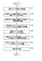
図8は、本発明の実施例のフローチャートを示す。ステップ801で、カメラ・ストロボを使用せずに、シーンの試験的な写真が撮影される。すなわち、試験的な写真は、周囲の照明だけで撮影される。
【0034】
ステップ802で、周囲光だけの試験的な写真の露出ヒストグラムが作成される。
【0035】
ステップ803で、周囲光だけの試験的な写真の飽和画素の数が認識される。
【0036】
ステップ804で、事前設定されたストロボ・エネルギーのカメラ・ストロボを使ってシーンの試験的な写真が撮影される。
【0037】
ステップ805で、試験的なストロボ写真の露出ヒストグラムが作成される。
【0038】
ステップ806で、試験的なストロボ写真の露出ヒストグラムから、周囲光だけの試験的な写真の飽和画素が除去される。
【0039】
ステップ807で、カメラは、得られた露出ヒストグラムを使用してストロボ・エネルギーを調整する。
【0040】
ステップ808で、カメラが最終写真を撮影する。
【0041】
また、最終写真前に周囲光のみの写真と試験的なストロボ写真の両方が撮影されるが、これらは互いに任意の順序で撮影されてもよいことに注意されたい。
【0042】
本発明の以上の説明は、例示と説明のために示された。この説明は、網羅的なものではなく、本発明を、開示した厳密な形態に限定するものでもなく、前記の教示を鑑みて他の修正および変形が可能である。実施形態は、本発明の原理およびその実際的な応用例を最も良く説明し、それにより、当業者が、意図された特定の使用に適合するような様々な実施形態および様々な修正において最も良く利用するように選択され記述された。併記の特許請求の範囲は、従来技術によって制限された範囲を除く本発明の他の代替実施形態を含むように解釈されるべきである。
【0043】
本発明は次の実施態様を含んでいる。
【0044】
1.カメラのストロボ・エネルギーを設定する方法であって、
a)事前設定されたストロボ・エネルギーを使用してシーンの第1の試験的な写真を撮影する段階(804)と、
b)周囲照明だけを使用して前記シーンの第2の試験的な写真を撮影する段階(801)と、
c)前記第2の試験的な写真の飽和画素を識別する段階(803)と、
d)前記第2の試験的な写真の飽和画素に関する情報を、前記第1の試験的な写真からの情報と組み合わせて、最終写真のストロボ・エネルギーを計算する段階(806,807)と、を含む方法。
【0045】
2.最終写真を撮影する段階(808)をさらに含む上記1に記載の方法。
【0046】
3.前記2つの試験的な写真に関する情報を収集する(802,805)ために露出ヒストグラムが使用される上記1に記載の方法。
【0047】
4.a)飽和画素が、写真内の最も明るい画素を表す露出ヒストグラム・ビン内にある画素として識別され(803)、
b)前記最終写真の前記ストロボ・エネルギーの前記計算の前に、前記第2の試験的な写真内の飽和画素の影響があらかじめ考慮される(806)上記2に記載の方法。
【0048】
5.前記最終写真の前記ストロボ・エネルギーの前記計算の前に、前記第2の試験的な写真の前記飽和画素の数が、前記第1の試験的な写真の前記露出ヒストグラム内の前記飽和画素の数から減算される(806)上記3に記載の方法。
【0049】
6.ストロボ(106)と、
周囲光だけを使用して得られた第2の試行写真からの情報を使用して、前記ストロボを使用して得られた第1の試験的な写真からのデータを修正し、前記修正したデータを使用して最終写真のストロボ・エネルギーを計算するように構成されたプロセッサと、を含むカメラ。
【0050】
7.前記2つの試験的な写真に関する情報を収集するために露出ヒストグラムが使用される上記5に記載のカメラ。
【0051】
8.a)飽和画素が、前記写真内の前記最も明るい画素を表す露出ヒストグラム・ビン内にある画素として識別され、b)最終写真の前記ストロボ・エネルギーの前記計算の前に、前記周囲光だけの試験的な写真内の飽和画素の影響があらかじめ考慮される上記6に記載の方法。
【0052】
9.最終写真の前記ストロボ・エネルギーの前記計算の前に、前記周囲光の試験的な写真内の前記飽和画素の数が、前記試験的なストロボ写真露出ヒストグラム内の前記飽和画素の数から減算される上記7に記載のディジタル・カメラ。
【0053】
10.a)周囲光を使用して第1の写真を撮影する手段と、
b)ストロボを使用して第2の写真を撮影する手段と、
c)前記第1の写真の飽和画素を識別する手段と、
d)前記第1の写真内の前記飽和画素に関する情報を前記第2の写真からの情報と組み合わせて、最終写真のストロボ・エネルギーを計算する手段と、を含むカメラ。
【図面の簡単な説明】
【図1】カメラの簡略ブロック図である。
【図2】シーン内にきわめて明るい対象物を有する写真のプリントの図である。
【図3】従来のストロボ・エネルギー選択方法を使用して撮影された図2に対応するシーンの露出ヒストグラムである。
【図4】ストロボを使用して試験的にシーンを撮影したときの図2に対応するシーンの露出ヒストグラムである。
【図5】周囲光だけを使用してシーンを撮影したときの図2に対応するシーンの露出ヒストグラムである。
【図6】本発明の実施形態によりシーンを撮影したときの図2に対応するシーンの露出ヒストグラムである。
【図7】本発明の実施形態により得られた図2に対応するシーンの写真のプリントの図である。
【図8】本発明の実施形態によるフローチャートである。
【符号の説明】
103 センサ
106 ストロボ
108 ストロボ電子回路
110 プロセッサ[0001]
BACKGROUND OF THE INVENTION
The present invention relates generally to photography, and more specifically to photography using a flash or strobe.
[0002]
[Prior art]
Cameras use a variety of techniques to ensure proper photo exposure. In general, the camera creates one or more pilot photos of the scene using the selected camera settings. In order to improve the exposure level, such a pilot photograph is analyzed to determine how to adjust the amount of light captured from the scene as well as the exposure. The camera then adjusts any of several settings so that proper exposure is achieved before taking the final photo.
[0003]
Camera settings that can be adjusted include shutter time (mechanical or electronic), lens aperture ratio, electronic amplification settings for signals in the camera (sometimes called system gain), to compensate for ambient light in the scene There is a setting for whether or not to strike the strobe, and a setting for how much energy is supplied to the strobe when the strobe is hit. In some cases, the camera user may specify some or all of the settings and have the camera adjust the remaining settings to achieve proper exposure.
[0004]
In order to determine the adjustments to be made, the camera assumes a proper exposure definition, and each camera incorporates information about how each possible adjustment affects the exposure of the final photo.
[0005]
When a strobe is used, a method is needed to determine the proper amount of energy to supply to the strobe. The more energy supplied to the strobe, the more light the strobe emits, resulting in a brighter photo exposure.
[0006]
In the present invention, the photograph may be a numerical representation of the scene captured by the camera and need not be a printed representation of the scene.
[0007]
A common way to determine the proper strobe energy is to take a trial photo with a strobe energy set to a known amount. The photograph obtained is examined and its exposure quality is evaluated. If adjustment is required, determine a new value for the strobe energy. Next, a final photo is taken using the calculated energy value. If you find that some areas of the pilot photo are fully exposed due to too much exposure, the energy level used for the final photo is the same as the strobe used for the pilot photo.・ Can be reduced from energy. One indication that an area is fully exposed is that the pixel data in that area of the photograph is saturated. Saturating means that the digital value representing those pixels is the highest value that the camera can show, and adding light to those pixels does not increase the digital value.
[0008]
However, this method may not give good results when the scene includes a small area of very bright light such as glare reflections or a self-luminous light source such as a lighting fixture or lamp. The camera assumes that the very bright areas are a result of the strobe energy used in the pilot photo, and it does not give the amount of strobe energy needed to properly expose the rest of the scene. May be rated low. Alternatively, the camera may interpret the bright area as sufficient illumination for the entire scene and choose not to use additional strobes, which may cause the photo to be underexposed. In either case, the photo is not properly exposed.
[0009]
[Problems to be solved by the invention]
There is a need for a technique for setting the strobe energy appropriately when the scene to be photographed includes a small and extremely bright area.
[0010]
[Means for Solving the Problems]
Adjust the camera's strobe energy to improve exposure. Get a trial exposure of the scene using only ambient light. Pixels that are found to be fully exposed or saturated in an ambient light-only trial photo are considered in advance in the calculation of the strobe energy appropriate for the final photo.
[0011]
DETAILED DESCRIPTION OF THE INVENTION
FIG. 1 shows a block diagram of a camera. The lens (101) collects light from a scene (not shown). The collected light is redirected (102) to form an image of the scene on the sensor (103). The sensor may be a sensor array such as a CCD element or a CMOS sensor. The operation of the lens may be controlled by a control signal (113) from a logic unit (110) that includes a microprocessor system. Similarly, the operation of the sensor may be controlled by a control signal (105) from the logic unit (110). An image information signal (104) flows from the sensor to the logic unit (110).
[0012]
A flash or strobe (106) can be utilized to provide additional light (107) to the scene. The strobe is operated by a strobe electronic circuit (108), which is controlled by a logic unit (110). The camera can include a display device (109) that can display image data. The camera can include a storage device (111) for storing and recalling image data and exchanging data with other devices (not shown). The camera user can manipulate various control inputs (112) to affect the operation of the camera.
[0013]
FIG. 2 shows a picture of a scene containing a small area of very bright light. In this case, a lit lamp is included in the photo. From this photo it is clear that the camera used to create the photo used a setting that made the photo too dark. Pictures can be greatly improved by better ways of changing camera settings that affect exposure.
[0014]
An exposure sensor for a digital camera or film camera essentially produces a numerical representation for each photograph taken. For each location in the picture called a “pixel” or “pixel”, the camera records a numerical value indicating the brightness of the scene at that location. In this case, the resulting scene representation is an array of numbers. A location in the array corresponds to a particular pixel or location in the scene, and the number stored in each array location represents the brightness of the scene at that location.
[0015]
In addition, the camera can optionally record information regarding the color at each pixel position of the scene to be photographed. To explain the present invention, only the luminance of each pixel is considered. The high luminance of the pixel can be calculated from the color information. For example, many cameras represent the color of a pixel using three components that indicate the contribution of light of red, green, and blue wavelengths to the luminance of the pixel. The total luminance of a pixel may be calculated as the sum of red, green, and blue contributions, as a weighted sum, or other combination of color information. Various methods for calculating pixel brightness from color information are well known in the art. It will be readily apparent to those skilled in the art that the present invention provides a function equivalent to a camera that records only luminance information for each pixel and a camera that also records color information.
[0016]
A common useful tool for analyzing photographic exposure is the exposure histogram. FIG. 3 shows an exposure histogram of the scene shown in FIG. The exposure histogram is constructed by dividing the exposure range of the camera into various “bins” (regions) and then counting how many pixels are in each bin from the image. For example, the camera used to generate FIG. 2 can represent pixel brightness as a value from 0 to 1,023. The histogram of FIG. 3 divides this luminance range into 64 bins. Therefore, bin 0 (301) collects the total number of pixels having luminance values in the range of 0-15 in the image. Bin 1 (302) collects the total number of pixels having luminance values ranging from 16 to 31 in the image. Subsequent bins follow the same pattern and end with bin 63 (303), which collects the total number of image pixels having luminance values from 1,008 to 1,023.
[0017]
Pixels with luminance values that enter bin 63 (303) are fully exposed or saturated. Increasing the exposure of such pixels does not affect the pixels in the bin. The camera cannot record luminance values exceeding 1,023. Pixels that are brighter than the level that results in a luminance value of 1,008 or more always enter the bin 63 (303). Such pixels do not respond when the exposure of the photo is high.
[0018]
However, when lowering the exposure of such pixels, their brightness values may be treated low, some or all of which may be counted in a lower numbered bin.
[0019]
In general, minimizing the number of pixels in the lowest numbered bin and minimizing the number of saturated pixels in a photo can lead to loss of photo information if both of these pixels are large, desirable. Cameras generally adjust the strobe energy to place most of the picture pixels in a bin that represents the average brightness of a typical scene, while at the same time strobe to minimize the number of pixels in the bins at both ends.・ Try to adjust energy.
[0020]
It is desirable to minimize the number of saturated pixels in an image when the scene to be photographed contains a small area of very bright light, because the conventional strobe energy selection method leads to a reduction in the quality of the photograph. The photo in FIG. 2 is a conventional photo taken with a known strobe energy setting, analyzing the exposure histogram of the resulting image, calculating a new value of strobe energy, and then taking the final photo. It was taken by the method.
[0021]
FIG. 4 shows an exposure histogram of a pilot photograph. Most of the pixels in the image fall into the lower numbered bins, but are also distributed approximately in bins 2-22 (401). If there are 1,973 saturated pixels entering bin 63 (402), this represents a properly exposed photograph. The camera assumed that saturated pixels were due to excessive strobe energy in order to enhance the quality of the photo, and therefore reduced the strobe energy before taking the final photo of FIG.
[0022]
Note that a pilot photo may have a different number of pixels than the final photo from CCD secondary sampling.
[0023]
FIG. 3 shows an exposure histogram of the image of FIG. It can be seen that the resulting image shows pixels in the histogram bin 6 and a smaller numbered bin (304), indicating an underexposed photo. However, a significant number of image pixels are still in bin 63 (303), indicating that the saturation of the pixels has not been eliminated by the decrease in strobe energy.
[0024]
Thus, underexposed photographs were obtained by conventional methods.
[0025]
This photo can be processed using a digital computer to correct the exposure. However, this approach may be inadequate because the image modifications necessary to improve exposure typically reveal or enhance annoying noise in the image.
[0026]
A better solution is to find a way for the camera to properly expose the photo when taking it.
[0027]
In an embodiment of the present invention, two pilot photographs are taken, one is taken using only ambient light from the scene without a strobe, and one is a preset strobe energy. Taken using the settings. The exposure settings used for both pilot photographs may be the same as those used when the strobe was used in the final image, such as exposure time, lens aperture, system gain, etc. These settings may be different, in which case the resulting exposure histogram may be adjusted for accurate comparison.
[0028]
The exposure histogram of the ambient light only photo is examined for saturated pixels. If saturated pixels are found, these saturated pixels cannot be attributed to the experimental strobe because no strobe was used in this experimental photo. Inevitably, saturated pixels must be from very bright areas in the scene itself. Accordingly, such pixels do not correspond to changes in strobe energy and may be considered in advance or ignored when calculating the strobe energy used for the final photo.
[0029]
For example, FIG. 5 shows an exposure histogram of the scene shown in FIG. 2 when shooting without a strobe. The exposure histogram generally shows an underexposed image but has 1,649 saturated pixels (501). Since no strobe was used, these pixels are saturated by the light source contained in the scene and do not respond to changes in strobe energy.
[0030]
This result is then combined with the exposure histogram of the same scene (information in FIG. 3) taken with a pilot strobe. In FIG. 4, 324 more pixels than in FIG. 5 are saturated. In the present invention, the camera calculates the strobe output based on an exposure histogram containing only 324 saturated pixels (along with the rest of the experimental strobe exposure histogram), so that the output is taken before the final photo is taken. Only slightly decreased.
[0031]
FIG. 6 shows an exposure histogram of the final photograph according to the present invention. Pixels similar in proportion to the pixels saturated in FIG. 3 are saturated (601), and an exposure histogram of the scene is taken by a conventional method, but the picture is exposed as a whole better than before.
[0032]
Although the sample embodiment increases the steps of the procedure for calculating strobe energy, the time required for the camera to take a picture may not necessarily increase. In general, test photos of several scenes are taken for the final photo for various reasons not related to strobe energy. One of such other experimental photos may be used to determine the number of saturated pixels in the ambient light only image, and therefore the increased steps will cause the camera to add additional photos. It is not always necessary to shoot.
[0033]
FIG. 8 shows a flowchart of an embodiment of the present invention. In
[0034]
At
[0035]
At
[0036]
At
[0037]
At
[0038]
At
[0039]
In
[0040]
At
[0041]
Also note that both the ambient light only photo and the experimental strobe photo are taken before the final photo, but they may be taken in any order with respect to each other.
[0042]
The foregoing description of the present invention has been presented for purposes of illustration and description. This description is not exhaustive and does not limit the invention to the precise form disclosed, and other modifications and variations are possible in light of the above teaching. The embodiments best describe the principles of the invention and its practical applications, so that those skilled in the art are best able in various embodiments and various modifications to suit a particular intended use. Selected and described for use. The appended claims should be construed to include other alternative embodiments of the invention except insofar as limited by the prior art.
[0043]
The present invention includes the following embodiments.
[0044]
1. A method for setting the strobe energy of a camera,
a) taking a first pilot picture of the scene using preset strobe energy (804);
b) taking a second pilot picture of the scene using only ambient lighting (801);
c) identifying (803) saturated pixels of the second pilot photo;
d) combining information about saturated pixels of the second experimental photo with information from the first experimental photo to calculate strobe energy of the final photo (806, 807); Including methods.
[0045]
2. The method of claim 1, further comprising the step of taking a final photograph (808).
[0046]
3. The method of claim 1, wherein an exposure histogram is used to collect information about the two pilot photographs (802, 805).
[0047]
4). a) A saturated pixel is identified as a pixel in the exposure histogram bin that represents the brightest pixel in the photo (803);
b) Prior to the calculation of the strobe energy of the final photo, the effect of saturated pixels in the second pilot photo is pre-considered (806) The method of claim 2 above.
[0048]
5). Prior to the calculation of the strobe energy of the final photo, the number of saturated pixels of the second experimental photo is the number of saturated pixels in the exposure histogram of the first experimental photo. Subtracted from (806).
[0049]
6). Strobe (106);
Using information from a second trial photo obtained using only ambient light, amend the data from the first pilot photo obtained using the strobe, and the corrected data And a processor configured to calculate the strobe energy of the final photo using a camera.
[0050]
7). 6. The camera of claim 5, wherein an exposure histogram is used to collect information about the two pilot photographs.
[0051]
8). a) a saturated pixel is identified as a pixel in the exposure histogram bin that represents the brightest pixel in the photo; b) a test of the ambient light only prior to the calculation of the strobe energy of the final photo. 7. The method according to 6 above, wherein the influence of saturated pixels in a typical photograph is considered in advance.
[0052]
9. Prior to the calculation of the strobe energy of the final photo, the number of saturated pixels in the ambient light test photo is subtracted from the number of saturated pixels in the test photo exposure histogram. 8. The digital camera as described in 7 above.
[0053]
10. a) means for taking a first photo using ambient light;
b) means for taking a second photo using a strobe;
c) means for identifying saturated pixels of the first photo;
d) means for combining information about the saturated pixels in the first photo with information from the second photo to calculate the strobe energy of the final photo.
[Brief description of the drawings]
FIG. 1 is a simplified block diagram of a camera.
FIG. 2 is a print of a photograph with a very bright object in the scene.
FIG. 3 is an exposure histogram of a scene corresponding to FIG. 2 taken using a conventional strobe energy selection method.
FIG. 4 is an exposure histogram of a scene corresponding to FIG. 2 when a scene is photographed experimentally using a strobe.
FIG. 5 is an exposure histogram of a scene corresponding to FIG. 2 when a scene is photographed using only ambient light.
6 is an exposure histogram of a scene corresponding to FIG. 2 when a scene is photographed according to an embodiment of the present invention.
FIG. 7 is a picture print of a scene corresponding to FIG. 2 obtained according to an embodiment of the present invention.
FIG. 8 is a flowchart according to an embodiment of the present invention.
[Explanation of symbols]
103
Claims (4)
a)事前設定されたストロボ・エネルギーを使用してシーンの第1の試験的な写真を撮影する段階と、
b)周囲照明だけを使用して前記シーンの第2の試験的な写真を撮影する段階と、
c)前記第2の試験的な写真の飽和画素を識別する段階と、
d)最終写真の前記ストロボ・エネルギーの前記計算の前に、前記第2の試験的な写真内の飽和画素の数を、前記第1の試験的な写真の露出ヒストグラム内の飽和画素の数から減算する段階と、
を含むことを特徴とする方法。A method for setting the strobe energy of a camera,
a) taking a first pilot picture of the scene using preset strobe energy;
b) taking a second pilot picture of the scene using only ambient lighting;
c) identifying saturated pixels of the second pilot photo;
d) Prior to the calculation of the strobe energy of the final photo, the number of saturated pixels in the second experimental photo is calculated from the number of saturated pixels in the exposure histogram of the first experimental photo. Subtracting , and
A method comprising the steps of :
飽和画素が、写真内の最も明るい画素を表す露出ヒストグラム・ビン内にある画素として識別されることを特徴とする請求項1に記載の方法。An exposure histogram is used to collect information about the two pilot photos, and
The method of claim 1, saturation pixels, characterized in that it is identified as a pixel in the exposure histogram bin representing the brightest pixel in the photograph.
周囲光だけを使用して得られた第2の試験的な写真からの情報を使用して、前記ストロボを使用して得られた第1の試験的な写真からのデータを修正し、前記修正したデータを使用して最終写真のストロボ・エネルギーを計算するように構成されたプロセッサと、を含み、
前記プロセッサが、最終写真の前記ストロボ・エネルギーの前記計算の前に、前記周囲光だけを使用して得られた前記第2の試験的な写真内の前記飽和画素の数を、前記ストロボを使用して得られた前記第1の試験的な写真の露出ヒストグラム内の前記飽和画素の数から減算することを特徴とするカメラ。Strobe,
Using information from a second experimental photograph obtained using only ambient light, modifying data from the first experimental photograph obtained using the strobe, and A processor configured to calculate the strobe energy of the final photo using the processed data ,
The processor uses the strobe to calculate the number of saturated pixels in the second pilot photo obtained using only the ambient light prior to the calculation of the strobe energy of the final photo. And subtracting from the number of saturated pixels in the exposure histogram of the first experimental photograph obtained .
前記2つの試験的な写真に関する情報を収集するために露出ヒストグラムが使用され、
飽和画素が、写真内の前記最も明るい画素を表す露出ヒストグラム・ビン内にある画素として識別されることを特徴とする請求項3に記載のカメラ。A digital camera,
An exposure histogram is used to gather information about the two pilot photos;
The camera of claim 3, wherein a saturated pixel is identified as a pixel in an exposure histogram bin that represents the brightest pixel in a photograph.
Applications Claiming Priority (2)
| Application Number | Priority Date | Filing Date | Title |
|---|---|---|---|
| US09/886,448 US6546203B2 (en) | 2001-06-21 | 2001-06-21 | Camera with adjustable strobe energy |
| US09/886448 | 2001-06-21 |
Publications (3)
| Publication Number | Publication Date |
|---|---|
| JP2003101876A JP2003101876A (en) | 2003-04-04 |
| JP2003101876A5 JP2003101876A5 (en) | 2005-05-12 |
| JP4021716B2 true JP4021716B2 (en) | 2007-12-12 |
Family
ID=25389065
Family Applications (1)
| Application Number | Title | Priority Date | Filing Date |
|---|---|---|---|
| JP2002178255A Expired - Fee Related JP4021716B2 (en) | 2001-06-21 | 2002-06-19 | Camera with strobe adjustment function |
Country Status (2)
| Country | Link |
|---|---|
| US (1) | US6546203B2 (en) |
| JP (1) | JP4021716B2 (en) |
Families Citing this family (23)
| Publication number | Priority date | Publication date | Assignee | Title |
|---|---|---|---|---|
| JP3806038B2 (en) * | 2002-01-07 | 2006-08-09 | 富士写真フイルム株式会社 | Image processing system and imaging apparatus |
| US6684028B2 (en) * | 2002-01-08 | 2004-01-27 | Olympus Optical Co., Ltd. | Camera apparatus, control method thereof and program |
| JP3986349B2 (en) * | 2002-04-04 | 2007-10-03 | 富士フイルム株式会社 | Image acquisition method |
| US7319489B2 (en) * | 2002-05-31 | 2008-01-15 | Sanyo Electric Co., Ltd. | Camera with strobe light |
| JP2004056713A (en) * | 2002-07-24 | 2004-02-19 | Sharp Corp | Portable device with photographing unit and exposure adjustment device |
| US20040246361A1 (en) * | 2003-06-09 | 2004-12-09 | Rastegar Jahangir S. | Preview illumination for a digital camera display |
| US7841533B2 (en) | 2003-11-13 | 2010-11-30 | Metrologic Instruments, Inc. | Method of capturing and processing digital images of an object within the field of view (FOV) of a hand-supportable digitial image capture and processing system |
| JP3748267B2 (en) | 2004-06-16 | 2006-02-22 | ソニー株式会社 | Imaging device |
| JP2006050337A (en) * | 2004-08-05 | 2006-02-16 | Sony Corp | Imaging apparatus, imaging method, and imaging control program |
| US7551797B2 (en) * | 2004-08-05 | 2009-06-23 | Canon Kabushiki Kaisha | White balance adjustment |
| JP4516500B2 (en) * | 2005-08-23 | 2010-08-04 | 富士フイルム株式会社 | Imaging device |
| US20070053677A1 (en) * | 2005-09-07 | 2007-03-08 | Point Grey Research Inc. | Strobe system |
| JP4667322B2 (en) | 2006-08-08 | 2011-04-13 | キヤノン株式会社 | Signal processing apparatus, imaging system, and signal processing method |
| JP4747065B2 (en) * | 2006-09-29 | 2011-08-10 | 富士通株式会社 | Image generation apparatus, image generation method, and image generation program |
| TW200820797A (en) * | 2006-10-23 | 2008-05-01 | Benq Corp | Photographing methods and systems, and machine readable medium thereof |
| US7697062B2 (en) * | 2006-11-08 | 2010-04-13 | Sony Ericsson Mobile Communications Ab | Camera and method in a camera |
| KR100897768B1 (en) * | 2007-05-01 | 2009-05-15 | 삼성전자주식회사 | Auto focusing method and devices that can use the method |
| US7859573B2 (en) | 2007-05-31 | 2010-12-28 | Aptina Imaging Corporation | Methods and apparatuses for image exposure correction |
| US8237850B2 (en) * | 2007-08-27 | 2012-08-07 | Sanyo Electric Co., Ltd. | Electronic camera that adjusts the distance from an optical lens to an imaging surface |
| JP2009276560A (en) * | 2008-05-14 | 2009-11-26 | Ricoh Co Ltd | Imaging apparatus and imaging method |
| JP4934123B2 (en) * | 2008-09-30 | 2012-05-16 | 富士フイルム株式会社 | Imaging apparatus and method |
| KR101217785B1 (en) * | 2011-04-14 | 2013-01-02 | 누비코 주식회사 | Video camera with adjustable brightness of light and method for adjusting of the same |
| US8804029B2 (en) * | 2012-06-22 | 2014-08-12 | Microsoft Corporation | Variable flash control for improved image detection |
Family Cites Families (2)
| Publication number | Priority date | Publication date | Assignee | Title |
|---|---|---|---|---|
| US6151073A (en) * | 1996-03-28 | 2000-11-21 | Fotonation, Inc. | Intelligent camera flash system |
| US6195127B1 (en) * | 1996-07-18 | 2001-02-27 | Sanyo Electric Co., Ltd. | Digital camera, having a flash unit, which determines proper flash duration through an assessment of image luminance and, where needed, a preliminary flash emission |
-
2001
- 2001-06-21 US US09/886,448 patent/US6546203B2/en not_active Expired - Lifetime
-
2002
- 2002-06-19 JP JP2002178255A patent/JP4021716B2/en not_active Expired - Fee Related
Also Published As
| Publication number | Publication date |
|---|---|
| US6546203B2 (en) | 2003-04-08 |
| US20020197071A1 (en) | 2002-12-26 |
| JP2003101876A (en) | 2003-04-04 |
Similar Documents
| Publication | Publication Date | Title |
|---|---|---|
| JP4021716B2 (en) | Camera with strobe adjustment function | |
| JP4236433B2 (en) | System and method for simulating fill flash in photography | |
| US8018525B2 (en) | Camera flash module and method for controlling same | |
| CN102104785B (en) | Image pickup apparatus and controlling method thereof | |
| US7916181B2 (en) | Method and device for creating high dynamic range pictures from multiple exposures | |
| US7551797B2 (en) | White balance adjustment | |
| US20050046739A1 (en) | System and method using light emitting diodes with an image capture device | |
| JP2006227613A (en) | Camera exposure program combined with image stabilizing function | |
| KR930701761A (en) | The process of determining the extra system speed and automatically optimizing the exposure parameters of the picture. | |
| JP2010193002A (en) | Imaging apparatus, image processing method and program | |
| JP2003234955A (en) | Image processing device, image processing program, and image processing method | |
| JP2015034850A (en) | Photographing device and photographing method | |
| KR100651813B1 (en) | Strobo control apparatus, and strobo control method | |
| JP4412109B2 (en) | Electronic camera having color balance adjustment function and program | |
| CN114143419A (en) | Dual-sensor camera system and its depth map calculation method | |
| JP2009063674A (en) | Imaging apparatus and flash control method | |
| JP4077217B2 (en) | Automatic exposure control device and program thereof | |
| JP2004186876A (en) | Digital camera | |
| JP4163463B2 (en) | Electronic camera | |
| US11825205B2 (en) | Computer implemented method and a system for obtaining a camera setting | |
| JP4539254B2 (en) | Electronic camera and image processing program | |
| JP2008022474A (en) | Imaging apparatus and imaging processing method | |
| JP4938989B2 (en) | Electronic camera | |
| JP2004349931A (en) | Digital camera | |
| JPH0341423A (en) | Exposure controller for camera |
Legal Events
| Date | Code | Title | Description |
|---|---|---|---|
| A521 | Request for written amendment filed |
Free format text: JAPANESE INTERMEDIATE CODE: A523 Effective date: 20040628 |
|
| A621 | Written request for application examination |
Free format text: JAPANESE INTERMEDIATE CODE: A621 Effective date: 20040628 |
|
| A977 | Report on retrieval |
Free format text: JAPANESE INTERMEDIATE CODE: A971007 Effective date: 20070209 |
|
| A131 | Notification of reasons for refusal |
Free format text: JAPANESE INTERMEDIATE CODE: A131 Effective date: 20070306 |
|
| A601 | Written request for extension of time |
Free format text: JAPANESE INTERMEDIATE CODE: A601 Effective date: 20070329 |
|
| A602 | Written permission of extension of time |
Free format text: JAPANESE INTERMEDIATE CODE: A602 Effective date: 20070404 |
|
| A521 | Request for written amendment filed |
Free format text: JAPANESE INTERMEDIATE CODE: A523 Effective date: 20070604 |
|
| TRDD | Decision of grant or rejection written | ||
| A01 | Written decision to grant a patent or to grant a registration (utility model) |
Free format text: JAPANESE INTERMEDIATE CODE: A01 Effective date: 20070918 |
|
| A61 | First payment of annual fees (during grant procedure) |
Free format text: JAPANESE INTERMEDIATE CODE: A61 Effective date: 20070927 |
|
| FPAY | Renewal fee payment (event date is renewal date of database) |
Free format text: PAYMENT UNTIL: 20101005 Year of fee payment: 3 |
|
| R150 | Certificate of patent or registration of utility model |
Ref document number: 4021716 Country of ref document: JP Free format text: JAPANESE INTERMEDIATE CODE: R150 Free format text: JAPANESE INTERMEDIATE CODE: R150 |
|
| FPAY | Renewal fee payment (event date is renewal date of database) |
Free format text: PAYMENT UNTIL: 20111005 Year of fee payment: 4 |
|
| R250 | Receipt of annual fees |
Free format text: JAPANESE INTERMEDIATE CODE: R250 |
|
| FPAY | Renewal fee payment (event date is renewal date of database) |
Free format text: PAYMENT UNTIL: 20121005 Year of fee payment: 5 |
|
| R250 | Receipt of annual fees |
Free format text: JAPANESE INTERMEDIATE CODE: R250 |
|
| FPAY | Renewal fee payment (event date is renewal date of database) |
Free format text: PAYMENT UNTIL: 20121005 Year of fee payment: 5 |
|
| S111 | Request for change of ownership or part of ownership |
Free format text: JAPANESE INTERMEDIATE CODE: R313113 |
|
| R250 | Receipt of annual fees |
Free format text: JAPANESE INTERMEDIATE CODE: R250 |
|
| FPAY | Renewal fee payment (event date is renewal date of database) |
Free format text: PAYMENT UNTIL: 20131005 Year of fee payment: 6 |
|
| R360 | Written notification for declining of transfer of rights |
Free format text: JAPANESE INTERMEDIATE CODE: R360 |
|
| R360 | Written notification for declining of transfer of rights |
Free format text: JAPANESE INTERMEDIATE CODE: R360 |
|
| R371 | Transfer withdrawn |
Free format text: JAPANESE INTERMEDIATE CODE: R371 |
|
| FPAY | Renewal fee payment (event date is renewal date of database) |
Free format text: PAYMENT UNTIL: 20131005 Year of fee payment: 6 |
|
| S111 | Request for change of ownership or part of ownership |
Free format text: JAPANESE INTERMEDIATE CODE: R313113 |
|
| FPAY | Renewal fee payment (event date is renewal date of database) |
Free format text: PAYMENT UNTIL: 20131005 Year of fee payment: 6 |
|
| R350 | Written notification of registration of transfer |
Free format text: JAPANESE INTERMEDIATE CODE: R350 |
|
| R250 | Receipt of annual fees |
Free format text: JAPANESE INTERMEDIATE CODE: R250 |
|
| R250 | Receipt of annual fees |
Free format text: JAPANESE INTERMEDIATE CODE: R250 |
|
| R250 | Receipt of annual fees |
Free format text: JAPANESE INTERMEDIATE CODE: R250 |
|
| R250 | Receipt of annual fees |
Free format text: JAPANESE INTERMEDIATE CODE: R250 |
|
| R250 | Receipt of annual fees |
Free format text: JAPANESE INTERMEDIATE CODE: R250 |
|
| R250 | Receipt of annual fees |
Free format text: JAPANESE INTERMEDIATE CODE: R250 |
|
| R250 | Receipt of annual fees |
Free format text: JAPANESE INTERMEDIATE CODE: R250 |
|
| R250 | Receipt of annual fees |
Free format text: JAPANESE INTERMEDIATE CODE: R250 |
|
| LAPS | Cancellation because of no payment of annual fees |