JP4019552B2 - Mounting structure of the call - Google Patents
Mounting structure of the call Download PDFInfo
- Publication number
- JP4019552B2 JP4019552B2 JP10862799A JP10862799A JP4019552B2 JP 4019552 B2 JP4019552 B2 JP 4019552B2 JP 10862799 A JP10862799 A JP 10862799A JP 10862799 A JP10862799 A JP 10862799A JP 4019552 B2 JP4019552 B2 JP 4019552B2
- Authority
- JP
- Japan
- Prior art keywords
- call
- mounting
- eaves ceiling
- mounting case
- caller
- Prior art date
- Legal status (The legal status is an assumption and is not a legal conclusion. Google has not performed a legal analysis and makes no representation as to the accuracy of the status listed.)
- Expired - Fee Related
Links
- 238000009434 installation Methods 0.000 claims 2
- 238000010276 construction Methods 0.000 claims 1
- XLYOFNOQVPJJNP-UHFFFAOYSA-N water Substances O XLYOFNOQVPJJNP-UHFFFAOYSA-N 0.000 description 3
- 235000013399 edible fruits Nutrition 0.000 description 2
- 230000000630 rising effect Effects 0.000 description 2
- 230000000694 effects Effects 0.000 description 1
- 230000001771 impaired effect Effects 0.000 description 1
- 239000000463 material Substances 0.000 description 1
Images



Landscapes
- Building Awnings And Sunshades (AREA)
Description
【0001】
【発明の属する技術分野】
本発明は軒樋の排水を外壁に沿う縦樋に流す呼び樋を軒天井に沿って取り付ける構造に関するものである。
【0002】
【従来の技術】
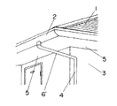
一般の雨樋装置は、図6に示すように屋根1の軒先に軒樋2を沿わせて架設し、外壁3の外面に沿って縦方向に縦樋4を配置し、軒樋2と縦樋4とを軒天井板5の下方に配置した呼び樋6′にて連通させてあった。
【0003】
【発明が解決しようとする課題】
ところが、上記従来例の呼び樋6′は軒天井板5の下方に所定の水勾配で傾斜して設けられており、呼び樋6′と建築物との一体感がなくて外観意匠を損ねるという問題があった。
【0004】
本発明は上記の点に鑑みてなされたものであり、呼び樋と建築物とに一体感があるように納めることができて外観を向上でき、しかも呼び樋を強固に取り付けることができる呼び樋の取り付け構造を提供することを課題とする。
【0005】
【課題を解決するための手段】
上記課題を解決するための本発明の請求項1の呼び樋の取り付け構造は、上下に偏平な筒状の呼び樋6を軒天井に埋設するように配設し、軒天井裏に架設した野縁7に呼び樋6の取り付け片8を引っ掛け支持して成ることを特徴とする。軒天井に埋設するように呼び樋6を取り付けたことにより、呼び樋6を外観よく仕舞うことができる。軒天井裏に架設した野縁7に呼び樋6の取り付け片8を引っ掛け支持したことにより、呼び樋6を野縁7にて強固に支持することができる。このために軒天井に埋設するために略水平に取り付けられて雨水の荷重がかかる呼び樋6でも呼び樋6を確実に支持することができる。
【0006】
また本発明の請求項2の呼び樋の取り付け構造は、請求項1において、呼び樋6を上下に偏平な筒状の呼び樋本体6aと、下方を開口せる断面コ字状の取り付けケース6bとで構成し、軒天井板5を取り付けるための野縁7a間に取り付けケース6bを配置すると共に取り付けケース6bの両側に設けた取り付け片8を上記野縁7aに引っ掛けて取り付けケース6bを野縁7aに支持し、取り付けケース6b内に呼び樋本体6aを嵌め込むと共に取り付けケース6bの両側片の内面に夫々設けた係止突条9と呼び樋本体6aの両側面に設けた係止凹条10とを呼び樋本体6aの長手方向のスライドにて係止し、呼び樋本体6aの下面と軒天井板5の下面とを略面一にして成ることを特徴とする。野縁7aにて取り付けケース6bを支持し、この取り付けケース6bに呼び樋本体6aを係止突条9と係止凹条10との係止にて簡単且つ強固に取り付けることができて呼び樋6を簡単且つ強固に支持できる。
【0007】
また本発明の請求項3の呼び樋の取り付け構造は、請求項1において、呼び樋6を上下に偏平な筒状の呼び樋本体6aと、下方を開口せる断面コ字状の取り付けケース6bとで構成し、軒天井板5を取り付けるための野縁7a間に取り付けケース6bを配置すると共に取り付けケース6bの両側に設けた取り付け片8を上記野縁7aに引っ掛けて取り付けケース6bを野縁7aに支持し、取り付けケース6bの下面開口の部分も軒天井板5を貼って閉塞し、取り付けケース6bと軒天井板5に囲まれる空間に呼び樋本体6aを嵌め込むと共に取り付けケース6bの両側片の内面に夫々設けた係止突条9と呼び樋本体6aの両側面に設けた係止凹条10とを呼び樋本体6aの長手方向のスライドにて係止して成ることを特徴とする。野縁7aにて取り付けケース6bを支持し、この取り付けケース6bに呼び樋本体6aを係止突条9と係止凹条10との係止にて簡単且つ強固に取り付けることができて呼び樋6を簡単且つ強固に支持できる。また呼び樋6が露出しないように下面を軒天井板5にて覆って外観よく仕舞うことができる。
【0008】
また本発明の請求項4の呼び樋の取り付け構造は、請求項1において、上下に偏平な筒状の呼び樋6の両側に一体に取り付け片8を設け、軒天井板5を取り付けるための野縁7a間に上記呼び樋6を配置すると共に両側の取り付け片8を両側の野縁7aに引っ掛けて呼び樋6を野縁7aに支持し、呼び樋6の下面と軒天井板5の下面とを略面一にして成ることを特徴とする。野縁7aにて呼び樋6を強固に支持できる。
【0009】
また本発明の請求項5の呼び樋の取り付け構造は、請求項1において、上下に偏平な筒状の呼び樋6の上面の中央の上方に取り付け片8を一体に設け、隣接する軒天井板5間に上記呼び樋6を埋め込むと共に呼び樋6の上方に架設した野縁7bに上記取り付け片8を引っ掛けて呼び樋6を野縁7bに支持し、呼び樋6の下面と軒天井板5の下面とを略面一にして成ることを特徴とする。野縁7bにて呼び樋6を強固に支持できる。
【0010】
【発明の実施の形態】
図2に示すように家屋のような建築物の屋根1の軒先には軒樋2を軒樋吊り具にて吊ることで取り付けてあり、軒樋2の長手方向の途中には集水器11を装着してある。軒天井部には不燃性材料にて形成せる軒天井板5が貼ってあり、軒天井に埋め込むように呼び樋6を取り付けてある。呼び樋6の一端は集水器11に接続してあり、呼び樋6の他端は外壁に沿わせて装着した縦樋12の上端に接続してあり、屋根1の雨水を軒樋2にて受け、この雨水を軒樋2、集水器11、呼び樋6を介して縦樋12に排水できるようになっている。
【0011】
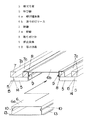
図1の例の場合、呼び樋6は偏平な角筒状の呼び樋本体6aと、下方を開口せる断面コ字状の取り付けケース6bとで構成してある。取り付けケース6bの両側片の上端には側方に向けて水平に突出する取り付け片8を設けてあり、取り付けケース6bの両側の側片の内面には係止突条9を長手方向に亙って突設してある。呼び樋本体6aの両側の側面には上記係止突条9が係止し得る係止凹条10を長手方向に亙って設けてあり、呼び樋本体6aの両側面の下端には水平方向に突出するフランジ片13を設けてある。軒天井裏には野縁7として軒天井板5を支持する野縁7aが複数本架設され、野縁7aの下面側に軒天井板5を貼ってある。軒天井板5は複数枚並べて貼られ、隣合う軒天井板5の端部同士は雌実14と雄実15との嵌合にて接続される。呼び樋6を取り付ける部分では下面側に軒天井板5が貼られず、一対の野縁7a間に間隔を隔ててある。この一対の野縁7a間には上から取り付けケース6bが嵌め込まれ、取り付けケース6bの両側の取り付け片8を野縁7aの上に載設して取り付けケース6bが取り付けられる。この取り付けケース6bを取り付けた後、呼び樋本体6aが呼び樋本体6aの長手方向にスライドさせることで取り付けケース6b内に取り付けられ、係止突条9と係止凹条10とが係止される。呼び樋本体6aを取り付けた状態で呼び樋本体6aの下面と軒天井板5の下面とが略面一になり、両側のフランジ片13が軒天井板5の端縁の下面に当接される。
【0012】
また図3は実施の形態の他の例を示す。本例も上記例と基本的に同じであり、異なる点だけ主に述べる。本例の場合も、呼び樋6は偏平な角筒状の呼び樋本体6aと、下方を開口せる断面コ字状の取り付けケース6bとで構成してある。この取り付けケース6bの両側片に取り付け片8が設けられるのであるが、本例の場合、取り付けケース6bの両側片の上端より下方の位置で水平に突出するように取り付け片8を設けてある。また本例の場合、呼び樋6を取り付ける位置でも軒天井板5を貼ってある。呼び樋6を取り付ける位置で一対の野縁7a間には上から取り付けケース6bが嵌め込まれ、取り付けケース6bの両側の取り付け片8を野縁7aの上に載設して取り付けケース6bが取り付けられる。取り付けケース6bを取り付けた状態で取り付けケース6bとの軒天井板5との間の空間に呼び樋本体6aが呼び樋本体6aの長手方向にスライドさせることで取り付けられ、係止突条9と係止凹条10とが係止される。
【0013】
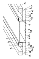
また図4は実施の形態の他の例を示す。本例の場合、呼び樋6が偏平な角筒状に形成されており、呼び樋6の両側の上端に水平方向に突出するように取り付け片8を一体に設けてあり、呼び樋6の両側の下端に水平方向に突出するフランジ片13を設けてある。また本例の場合、軒天井板5の下面に凹溝16aと凸部16bとよりなる凹凸柄16を設けてあるが、呼び樋6の下面にも凹溝16aと凸部16bよりなる凹凸柄16を設けてあり、軒天井板5の下面の凹凸柄16と呼び樋6の下面の凹凸柄16とを同じ柄にしてある。呼び樋6を取り付ける部分では一対の野縁7a間に軒天井板5が貼られておらず、この一対の野縁7a間に呼び樋6が呼び樋6の長手方向にスライドさせることで取り付けられる。呼び樋6を取り付けたとき、呼び樋6の両側の取り付け片8が野縁7aに載設されて野縁7aに呼び樋6が支持される。また呼び樋6の下面と軒天井板5の下面とが略面一になり、両側のフランジ片13が軒天井板5の端縁の下面に当接される。
【0014】
また図5は実施の形態の他の例を示すものである。本例も上記例と基本的に同じであり、異なる点だけを主に述べる。呼び樋6の上面の幅方向の中央の近傍には垂直方向に向けて立ち上がり片17を突設してあり、立ち上がり片17の上端には水平方向に突出する取り付け片8を一体に設けてある。野縁7としての野縁7aにて軒天井板5を支持してあり、また野縁7としての野縁7bが呼び樋6を取り付ける箇所に架設してある。本例の場合も呼び樋6を取り付ける箇所には軒天井板5が貼られていない。そしてこの軒天井板5が貼られていない部分には呼び樋6が呼び樋6の長手方向にスライドさせることで取り付けられる。呼び樋6を取り付けたとき、呼び樋6の中央の取り付け片8が野縁7bに載設されて野縁7bに呼び樋6が支持される。また呼び樋6の下面と軒天井板5の下面とが略面一になり、両側のフランジ片13が軒天井板5の端縁の下面に当接される。
【0015】
【発明の効果】
本発明の請求項1の発明は、上下に偏平な筒状の呼び樋を軒天井に埋設するように配設し、軒天井裏に架設した野縁に呼び樋の取り付け片を引っ掛け支持しているものであって、軒天井に埋設するように呼び樋を取り付けたことで、呼び樋を外観よく仕舞うことができるものであり、しかも軒天井裏に架設した野縁に呼び樋の取り付け片を引っ掛け支持したことで、呼び樋を野縁にて強固に支持することができものであり、従って軒天井に埋設するために略水平に取り付けられて雨水の荷重がかかる呼び樋でも呼び樋を確実に支持することができるものである。
【0016】
また本発明の請求項2の発明は、請求項1において、呼び樋を上下に偏平な筒状の呼び樋本体と、下方を開口せる断面コ字状の取り付けケースとで構成し、軒天井板を取り付けるための野縁間に取り付けケースを配置すると共に取り付けケースの両側に設けた取り付け片を上記野縁に引っ掛けて取り付けケースを野縁に支持し、取り付けケース内に呼び樋本体を嵌め込むと共に取り付けケースの両側片の内面に夫々設けた係止突条と呼び樋本体の両側面に設けた係止凹条とを呼び樋本体の長手方向のスライドにて係止し、呼び樋本体の下面と軒天井板の下面とを略面一にしているので、野縁にて取り付けケースを支持し、この取り付けケースに呼び樋本体を係止突条と係止凹条との係止にて簡単且つ強固に取り付けることができて呼び樋を簡単且つ強固に支持できるものである。
【0017】
また本発明の請求項3の発明は、請求項1において、呼び樋を上下に偏平な筒状の呼び樋本体と、下方を開口せる断面コ字状の取り付けケースとで構成し、軒天井板を取り付けるための野縁間に取り付けケースを配置すると共に取り付けケースの両側に設けた取り付け片を上記野縁に引っ掛けて取り付けケースを野縁に支持し、取り付けケースの下面開口の部分も軒天井板を貼って閉塞し、取り付けケースと軒天井板に囲まれる空間に呼び樋本体を嵌め込むと共に取り付けケースの両側片の内面に夫々設けた係止突条と呼び樋本体の両側面に設けた係止凹条とを呼び樋本体の長手方向のスライドにて係止しているので、野縁にて取り付けケースを支持し、この取り付けケースに呼び樋本体を係止突条と係止凹条との係止にて簡単且つ強固に取り付けることができて呼び樋を簡単且つ強固に支持できるものであり、また呼び樋が露出しないように下面を軒天井板にて覆って外観よく仕舞うことができるものである。
【0018】
また本発明の請求項4の発明は、請求項1において、上下に偏平な筒状の呼び樋の両側に一体に取り付け片を設け、軒天井板を取り付けるための野縁間に上記呼び樋を配置すると共に両側の取り付け片を両側の野縁に引っ掛けて呼び樋を野縁に支持し、呼び樋の下面と軒天井板の下面とを略面一にしているので、野縁にて呼び樋を強固に支持できるものである。
【0019】
また本発明の請求項5の発明は、請求項1において、上下に偏平な筒状の呼び樋の上面の中央の上方に取り付け片を一体に設け、隣接する軒天井板間に上記呼び樋を埋め込むと共に呼び樋の上方に架設した野縁に上記取り付け片を引っ掛けて呼び樋を野縁に支持し、呼び樋の下面と軒天井板の下面とを略面一にしているので、野縁にて呼び樋を強固に支持できるものである。
【図面の簡単な説明】
【図1】本発明の実施の形態の一例の要部の分解斜視図である。
【図2】同上の全体の構造を示す概略斜視図である。
【図3】同上の他の例の要部の分解斜視図である。
【図4】同上の他の例の要部の斜視図である。
【図5】同上の他の例の要部の斜視図である。
【図6】従来例の斜視図である。
【符号の説明】
5 軒天井板
6 呼び樋
6a 呼び樋本体
6b 取り付けケース
7 野縁
7a 野縁
7b 野縁
8 取り付け片
9 係止突条
10 係止凹条[0001]
BACKGROUND OF THE INVENTION
The present invention relates to a structure in which a call that allows drainage of eaves to flow along a vertical wall along an outer wall is attached along the eaves ceiling.
[0002]
[Prior art]
As shown in FIG. 6, a general gutter apparatus is constructed with an
[0003]
[Problems to be solved by the invention]
However, the call 6 'of the above-described conventional example is provided below the
[0004]
The present invention has been made in view of the above points, and can be accommodated so that the call and the building have a sense of unity so that the appearance can be improved and the call can be firmly attached. It is an object to provide a mounting structure.
[0005]
[Means for Solving the Problems]
According to a first aspect of the present invention for solving the above-mentioned problem, the call attachment structure according to the first aspect of the present invention is arranged such that a flat
[0006]
According to a second aspect of the present invention, there is provided a mounting structure for a caller according to the first aspect, wherein the
[0007]
According to a third aspect of the present invention, there is provided a mounting structure for a caller according to the first aspect of the present invention, wherein the
[0008]
According to a fourth aspect of the present invention, there is provided a structure for attaching the
[0009]
According to a fifth aspect of the present invention, there is provided a call attachment structure according to the first aspect, wherein the
[0010]
DETAILED DESCRIPTION OF THE INVENTION
As shown in FIG. 2, the
[0011]
In the case of the example of FIG. 1, the
[0012]
FIG. 3 shows another example of the embodiment. This example is basically the same as the above example, and only the differences will be mainly described. Also in this example, the
[0013]
FIG. 4 shows another example of the embodiment. In the case of this example, the
[0014]
FIG. 5 shows another example of the embodiment. This example is basically the same as the above example, and only the differences will be mainly described. A rising
[0015]
【The invention's effect】
According to the first aspect of the present invention, a flat cylindrical call-up is arranged so as to be embedded in the eaves ceiling, and a hook is attached to and supported by a field edge constructed on the back of the eaves ceiling. By attaching a call so as to be embedded in the eaves ceiling, the call can be finished with a good appearance, and a call attachment piece is attached to the field edge erected on the back of the eaves ceiling. By hooking and supporting, the call can be firmly supported at the edge of the field, so it can be securely mounted even in a call that is mounted almost horizontally to embed the eaves ceiling and is loaded with rainwater. Can be supported.
[0016]
The invention according to
[0017]
The invention according to
[0018]
According to a fourth aspect of the present invention, in the first aspect of the present invention, in the first aspect, mounting pieces are integrally provided on both sides of a vertically-shaped cylindrical call-up, and the call-up is provided between the field edges for attaching the eaves ceiling plate. It is placed and hooks on both sides are hooked on the field edges on both sides to support the call frame on the field edge, and the lower surface of the call frame is substantially flush with the lower surface of the eaves ceiling board. Can be firmly supported.
[0019]
In addition, the invention of
[Brief description of the drawings]
FIG. 1 is an exploded perspective view of a main part of an example of an embodiment of the present invention.
FIG. 2 is a schematic perspective view showing the overall structure of the above.
FIG. 3 is an exploded perspective view of a main part of another example of the above.
FIG. 4 is a perspective view of a main part of another example of the above.
FIG. 5 is a perspective view of a main part of another example of the above.
FIG. 6 is a perspective view of a conventional example.
[Explanation of symbols]
5
Claims (5)
Priority Applications (1)
| Application Number | Priority Date | Filing Date | Title |
|---|---|---|---|
| JP10862799A JP4019552B2 (en) | 1999-04-15 | 1999-04-15 | Mounting structure of the call |
Applications Claiming Priority (1)
| Application Number | Priority Date | Filing Date | Title |
|---|---|---|---|
| JP10862799A JP4019552B2 (en) | 1999-04-15 | 1999-04-15 | Mounting structure of the call |
Publications (2)
| Publication Number | Publication Date |
|---|---|
| JP2000297505A JP2000297505A (en) | 2000-10-24 |
| JP4019552B2 true JP4019552B2 (en) | 2007-12-12 |
Family
ID=14489599
Family Applications (1)
| Application Number | Title | Priority Date | Filing Date |
|---|---|---|---|
| JP10862799A Expired - Fee Related JP4019552B2 (en) | 1999-04-15 | 1999-04-15 | Mounting structure of the call |
Country Status (1)
| Country | Link |
|---|---|
| JP (1) | JP4019552B2 (en) |
-
1999
- 1999-04-15 JP JP10862799A patent/JP4019552B2/en not_active Expired - Fee Related
Also Published As
| Publication number | Publication date |
|---|---|
| JP2000297505A (en) | 2000-10-24 |
Similar Documents
| Publication | Publication Date | Title |
|---|---|---|
| JP7176789B2 (en) | Eaves structure | |
| JP3842023B2 (en) | External wall siding fixing structure | |
| JP3509571B2 (en) | Installation structure of the gutter | |
| JP2000297505A (en) | Installation structure of the gutter | |
| JP4269455B2 (en) | Mounting structure of the call | |
| JPH0119695Y2 (en) | ||
| JPH108687A (en) | Architectural wall panels, roof structures and wall structures | |
| JP2020084486A (en) | Eaves structure and its construction method | |
| JP2580883Y2 (en) | Balcony drainage structure | |
| JPS6132031Y2 (en) | ||
| JP2003064895A (en) | Installation structure of wall panel on floor pan | |
| JP2023123926A (en) | Vertical roof exterior structure | |
| JP2019007238A (en) | Eaves structure | |
| JP3480232B2 (en) | Eave gutter mounting structure | |
| JPS6214247Y2 (en) | ||
| JP4390323B2 (en) | Parapet structure | |
| JP2757145B2 (en) | Tile roof skylight mounting structure | |
| JPH0330494Y2 (en) | ||
| KR200187275Y1 (en) | A structure of a metal tile | |
| JP3065071U (en) | Cover plate of expansion joint device for roof | |
| JPS58785Y2 (en) | joinery mounting bracket | |
| JPS6317782Y2 (en) | ||
| JP2900779B2 (en) | Roof shingle and shingle roof structure using the shingle | |
| JP2789164B2 (en) | Mounting structure of bottom drainer | |
| JP3584202B2 (en) | Vertical roof exterior structure |
Legal Events
| Date | Code | Title | Description |
|---|---|---|---|
| A621 | Written request for application examination |
Free format text: JAPANESE INTERMEDIATE CODE: A621 Effective date: 20060412 |
|
| A977 | Report on retrieval |
Free format text: JAPANESE INTERMEDIATE CODE: A971007 Effective date: 20070502 |
|
| TRDD | Decision of grant or rejection written | ||
| A01 | Written decision to grant a patent or to grant a registration (utility model) |
Free format text: JAPANESE INTERMEDIATE CODE: A01 Effective date: 20070904 |
|
| A61 | First payment of annual fees (during grant procedure) |
Free format text: JAPANESE INTERMEDIATE CODE: A61 Effective date: 20070917 |
|
| FPAY | Renewal fee payment (event date is renewal date of database) |
Free format text: PAYMENT UNTIL: 20101005 Year of fee payment: 3 |
|
| FPAY | Renewal fee payment (event date is renewal date of database) |
Free format text: PAYMENT UNTIL: 20101005 Year of fee payment: 3 |
|
| S533 | Written request for registration of change of name |
Free format text: JAPANESE INTERMEDIATE CODE: R313533 |
|
| FPAY | Renewal fee payment (event date is renewal date of database) |
Free format text: PAYMENT UNTIL: 20101005 Year of fee payment: 3 |
|
| R350 | Written notification of registration of transfer |
Free format text: JAPANESE INTERMEDIATE CODE: R350 |
|
| FPAY | Renewal fee payment (event date is renewal date of database) |
Free format text: PAYMENT UNTIL: 20101005 Year of fee payment: 3 |
|
| FPAY | Renewal fee payment (event date is renewal date of database) |
Free format text: PAYMENT UNTIL: 20111005 Year of fee payment: 4 |
|
| FPAY | Renewal fee payment (event date is renewal date of database) |
Free format text: PAYMENT UNTIL: 20111005 Year of fee payment: 4 |
|
| FPAY | Renewal fee payment (event date is renewal date of database) |
Free format text: PAYMENT UNTIL: 20121005 Year of fee payment: 5 |
|
| FPAY | Renewal fee payment (event date is renewal date of database) |
Free format text: PAYMENT UNTIL: 20131005 Year of fee payment: 6 |
|
| LAPS | Cancellation because of no payment of annual fees |