JP4019210B2 - Horizontal ruler with clip - Google Patents
Horizontal ruler with clip Download PDFInfo
- Publication number
- JP4019210B2 JP4019210B2 JP2002101926A JP2002101926A JP4019210B2 JP 4019210 B2 JP4019210 B2 JP 4019210B2 JP 2002101926 A JP2002101926 A JP 2002101926A JP 2002101926 A JP2002101926 A JP 2002101926A JP 4019210 B2 JP4019210 B2 JP 4019210B2
- Authority
- JP
- Japan
- Prior art keywords
- horizontal
- tool
- movable clip
- clip
- movable
- Prior art date
- Legal status (The legal status is an assumption and is not a legal conclusion. Google has not performed a legal analysis and makes no representation as to the accuracy of the status listed.)
- Expired - Fee Related
Links
Images


Landscapes
- Length-Measuring Instruments Using Mechanical Means (AREA)
- A Measuring Device Byusing Mechanical Method (AREA)
Description
【0001】
[発明の属する技術分野]
本発明は、対象物の垂直・水平基準位置を出す物であり、一般的な水平測定においては、対象物に対し水平に置くことができ、又立直な対象物の垂直基準測定は、本発明の挟み具A・B部を立直対象物に挟むことで、水平▲8▼気泡部が挟み部と90度になり対象物を左右に動かすことで基準線(左・右)内に気泡が入れば、垂直の基準測定ができることを特徴とした本発明である。
【0002】
[従来の技術]
一般的な水平規では、多種多様な物があり、中には水平規底面に磁石板が付いた物等が存在する。しかし垂直面に対して取り付けする際に材質によっては立直側面に片手で固定しなければならない水平規が一般的である。それ故に、作業上においては水平規を片手で持ったままとなる為、もう一方の手しか使えない事が高所及び危険な場所等での使用の際の危険性・正確な測定ができない等のいろいろな問題が一般的な水平規では生じやすいのである。
【0003】
[発明が解決しようとする課題]
一般の水平規においての使用法は垂直・水平物に対して、磁気及び手等で取り付け測定するものが一般的である。他にも精密機具として、光センサー、工業用にも多種多様な水平規が存在する。しかし本発明は簡単に取り付けでき、更にはスピーディに作業が行える。それによって立直な垂直物に本発明を挟むことで、作業の時間効率が計れる等の利点を目的とした新規な本発明を提供するものである。
【0004】
[課題を解決するための手段]
請求項1に記載の挟み具付水平具は、水平規取付台5と、水平規取付台5に内蔵された水平規本体12と、水平規取付台5の一端部に設けられた可動挟み具Aとを備え、可動挟み具Aは、前記水平規取付台5に対して90度に立直するようになっており、可動挟み具Aは、可動挟み具Bを備え、可動挟み具Bは、前記可動挟み具Aの側面に、前記可動挟み具Aの前記水平規取付台5の一端部側となる一端部と反対側の他端部から、前記可動挟み具Aの前記水平規取付台5の一端部側となる一端部への方向に対し、平行又は概ね平行になるように設けられた、支持軸を有し、前記可動挟み具Aの側面に対し、スプリング8により開閉するようにされている。
請求項2に記載の挟み具付水平具は、請求項1に記載の挟み具付水平具の、水平規本体12が、その長さ方向が、水平規取付台5の長さ方向と順方向になるように、水平規取付台5に内蔵されている。
請求項3に記載の挟み具付水平具は、請求項1又は請求項2に記載の挟み具付水平具の、可動挟み具Aが、水平規取付台5の一端部を中心に回転可能に設けられている。
【0005】
[発明の実施の形態]
上記手段によると本発明は、垂直・水平の基準を測定するにあたり、作業上での危険性、効率化、正確性等を考えた発明である。一例で説明すると立直な垂直物を外壁の高所な所へ取り付けする時等、垂直かどうか測定するには、何らかの基準により垂直物が垂直又は水平かを決定しなければならない。そこで本発明の挟み具付き水平規を取り付けすることにより手軽に、効率よく測定できることとなる。
【0006】
〔実施例〕 以下本発明の実施例を図面に基づいての説明
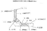
図1乃至図3は、本発明に係る挟み具付き水平規の一実施例を示すものである。図1では、5.水平規取付台の内部に水平規本体が内蔵されている、水平状態での測定対象物の水平基準を測定する際は、14.底部を測定対象物の上へ置き、測定する5.水平規取付台の6.基準線左と7.基準線右の間へ左右平等に位置する所が測定値であることを示す基準線又は12.水平規本体の中には9.液体と8.気泡が封じてある。立直物での取り付けとして、1.可動挟み具A及び2.可動挟み具Bを測定対象物の13.押さえ部へ握って挟み込む際、3.スプリングにより1.可動挟み具A及び2.可動挟み具Bを開閉する構成となっている。1.可動挟み具Aは、5.水平規取付台の4.ネジ部と11.回転面に取り付けられいる。1.可動挟み具A及び2.可動挟み具Bが図示の通り垂直状態になり、5.水平規取付台に対して90度となっていることが前提とされる。そこで1.可動挟み具A及び可動挟み具Bを取り付けた状態で左右に対象物を移動すれば8.気泡が動く為、基準測定ができる。図2は、本発明を90度に立直した側面図であり、図3は、本発明を折り畳んだ側面図である。図示3で示すとおり11.回転面を有し、5.水平規取付台へ1.可動挟み具A及び2.可動挟み具Bを折り畳むことができる。その際10.ツメと5.水平規取付台との隙間ができ、ポケット又はズボン等に取り付けすることができる。更には折り畳んだ状態で、水平対象物に置いて測定もできる。以上が、新規な発明である。
【0007】
〔発明の効果〕
本発明は、5.水平規取付台より90度に立直した1.可動挟み具A及び2.可動挟み具Bを有したもので、全ての対象物に対し、置く又は挟むことができる新規な本発明である。たとえば一例で説明すると、エアコン取付工事の場合、外部で一般的に多く利用されている配管カバーを垂直に取り付ける作業では、時には取り付け面が広範囲になってしまう為、左右に基準の物がなくメジャーが使用しにくい等、作業効率上非常に難点もあり得る。特に2階等の二連ハシゴの使用時等、片手でドリル、ねじ、配管カバー、メジャー等を持つこともあり、大変危険である。その他に、エアコン室内機の取付板においても、必ず垂直・水平を測定しなければならない。そこで本発明を上記一例で示すとおり、対象物に本発明を挟むことですべての場所での作業の効率化・安全性を図ることができる。上記一例以外でも、建築関係等のあらゆる物においても本発明の効果を得ることができた。
【図面の簡単な説明】
【図1】本発明を示した斜視図である
【図2】本発明を90度に立直した側面図である
【図3】本発明を折り畳んだ側面図である
【符号の説明】
1.可動挟み具A
2.可動挟み具B
3.スプリング
4.ネジ部
5.水平規取付台
6.基準線左
7.基準線右
8.気泡
9.液体
10.ツメ
11.回転面
12.水平規本体
13.押さえ部
14.底部[0001]
[Technical field to which the invention belongs]
The present invention provides a vertical / horizontal reference position of an object. In general horizontal measurement, the object can be placed horizontally with respect to the object. By sandwiching the sandwiching tool A / B part between the vertical objects, the horizontal 8) bubble part is 90 degrees from the sandwiching part and moving the object left and right causes bubbles to enter the reference line (left and right). Thus, the present invention is characterized in that vertical reference measurement can be performed.
[0002]
[Conventional technology]
There are a wide variety of general horizontal standards, and some of them have a magnet plate on the bottom of the horizontal standard. However, a horizontal ruler that must be fixed to the vertical side with one hand is generally used depending on the material when it is attached to the vertical surface. Therefore, since the leveling rule is held with one hand during work, the danger of using it in high places and dangerous places cannot be accurately measured because only the other hand can be used. These problems are likely to occur with a general level ruler.
[0003]
[Problems to be solved by the invention]
In general, the usage of the horizontal ruler is to measure and attach to a vertical or horizontal object by magnetism or hand. In addition, there are various kinds of horizontal scales for optical sensors and industrial use as precision instruments. However, the present invention can be easily attached and can be operated quickly. Thus, by sandwiching the present invention between upright vertical objects, the present invention is intended to provide a novel present invention aimed at advantages such as time efficiency of work.
[0004]
[Means for solving problems]
The leveling tool with a pinch according to claim 1 includes a leveling table 5, a leveling body 12 built in the leveling table 5, and a movable pinching tool provided at one end of the leveling table 5. A, the movable clip tool A is adapted to stand up to 90 degrees with respect to the leveling table 5, the movable clip tool A includes the movable clip tool B, and the movable clip tool B is From the other end of the movable clip A on the side opposite to the one end of the horizontal clip mount 5 on the side surface of the movable clip A, the horizontal clip mount 5 of the movable clip A is provided. The support shaft is provided so as to be parallel or substantially parallel to the direction toward the one end portion which is the one end portion side, and is opened and closed by a
The horizontal tool with a pinch tool according to
The horizontal tool with a pinch tool according to claim 3 is configured such that the movable pinch tool A of the horizontal tool with a pinch tool according to
[0005]
[Embodiment of the Invention]
According to the above-described means, the present invention is an invention that takes into account operational risks, efficiency, accuracy, and the like when measuring vertical and horizontal standards. As an example, to measure whether a vertical object is vertical, such as when a vertical object is attached to a high place on an outer wall, it is necessary to determine whether the vertical object is vertical or horizontal by some criteria. Therefore, it is possible to easily and efficiently measure by attaching the leveling instrument with the pinching tool of the present invention.
[0006]
[Embodiments] Embodiments of the present invention will now be described with reference to the drawings. FIGS. 1 to 3 show an embodiment of a leveling instrument with a pinch according to the present invention. In FIG. When measuring the horizontal reference of an object to be measured in a horizontal state, where the horizontal main body is built in the horizontal mounting base, 4. Place the bottom on the object to be measured and measure. 6. Horizontal mounting base 6. Reference line left and 11. A reference line indicating that a place located between the right and left sides of the reference line is a measurement value or 12. In the horizontal ruler body, 9. 7. with liquid Air bubbles are sealed. As installation on a vertical object: Movable clipper A and 2. 12. Move the movable clip B of the object to be measured. 2. When grasping and pinching the holding part, 1. By spring Movable clipper A and 2. The movable clip B is configured to open and close. 1. The movable clip tool A is 5. 4 of horizontal mounting base. 10. Screw part and It is attached to the rotating surface. 1. Movable clipper A and 2. 4. The movable clip B is in a vertical state as shown in the figure. It is assumed that the angle is 90 degrees with respect to the horizontal mounting base. So 1. If the object is moved to the left and right with the movable clip A and the movable clip B attached, 8. Since bubbles move, standard measurement is possible. FIG. 2 is a side view of the present invention turned up to 90 degrees, and FIG. 3 is a side view of the present invention folded. As shown in FIG. 4. having a rotating surface; To leveling table 1. Movable clipper A and 2. The movable clip tool B can be folded. In that case, 10. Claw and 5. There is a gap with the leveling table, and it can be attached to a pocket or pants. Furthermore, it can be measured by placing it on a horizontal object in a folded state. The above is a novel invention.
[0007]
〔The invention's effect〕
The present invention relates to 5. 1. Upright from the horizontal mounting base at 90 degrees. Movable clipper A and 2. This is a novel invention that has a movable clip B and can be placed or pinched on all objects. For example, in the case of air conditioner installation work, when installing a pipe cover that is commonly used outside in the vertical direction, the installation surface will sometimes be wide, so there is no standard thing on the left and right. However, it may be difficult to use, such as difficult to use. In particular, when using a double ladder on the second floor, etc., holding a drill, screw, piping cover, measure, etc. with one hand is very dangerous. In addition, vertical and horizontal measurements must always be made on the mounting plates of air conditioner indoor units. Therefore, as shown in the above example, the present invention is sandwiched between objects to improve the efficiency and safety of work in all locations. In addition to the above example, the effects of the present invention were able to be obtained in all things related to construction.
[Brief description of the drawings]
FIG. 1 is a perspective view showing the present invention. FIG. 2 is a side view of the present invention uprighted by 90 degrees. FIG. 3 is a side view of the present invention folded.
1. Movable clipper A
2. Movable clipper B
3. Spring 4. 4. Screw part Leveling table 6. Reference line left 7. Reference line right 8. Bubble 9
Claims (3)
前記水平規取付台5に内蔵された水平規本体12と、
前記水平規取付台5の一端部に設けられた可動挟み具Aとを備え、
前記可動挟み具Aは、前記水平規取付台5に対して90度に立直するようになっており、
前記可動挟み具Aは、可動挟み具Bを備え、
前記可動挟み具Bは、
前記可動挟み具Aの側面に、前記可動挟み具Aの前記水平規取付台5の一端部側となる一端部と反対側の他端部から、前記可動挟み具Aの前記水平規取付台5の一端部側となる一端部への方向に対し、平行又は概ね平行になるように設けられた、支持軸を有し、
前記可動挟み具Aの側面に対し、スプリング8により開閉するようにされている、挟み具付水平具。A horizontal mounting base 5;
A leveling body 12 built in the leveling table 5;
A movable clip A provided at one end of the leveling table 5;
The movable clip tool A is adapted to stand up to 90 degrees with respect to the leveling table 5.
The movable clip tool A includes a movable clip tool B,
The movable clip tool B is
From the other end of the movable clip A on the side opposite to the one end of the horizontal clip mount 5 on the side surface of the movable clip A, the horizontal clip mount 5 of the movable clip A is provided. the to the direction of the one end portion side becomes an end portion, provided so as to be parallel or generally parallel, it has a support shaft,
A horizontal tool with a clamp, which is configured to be opened and closed by a spring 8 with respect to the side surface of the movable clamp A.
Priority Applications (1)
| Application Number | Priority Date | Filing Date | Title |
|---|---|---|---|
| JP2002101926A JP4019210B2 (en) | 2002-02-26 | 2002-02-26 | Horizontal ruler with clip |
Applications Claiming Priority (1)
| Application Number | Priority Date | Filing Date | Title |
|---|---|---|---|
| JP2002101926A JP4019210B2 (en) | 2002-02-26 | 2002-02-26 | Horizontal ruler with clip |
Publications (3)
| Publication Number | Publication Date |
|---|---|
| JP2003247825A JP2003247825A (en) | 2003-09-05 |
| JP2003247825A5 JP2003247825A5 (en) | 2005-09-22 |
| JP4019210B2 true JP4019210B2 (en) | 2007-12-12 |
Family
ID=28672162
Family Applications (1)
| Application Number | Title | Priority Date | Filing Date |
|---|---|---|---|
| JP2002101926A Expired - Fee Related JP4019210B2 (en) | 2002-02-26 | 2002-02-26 | Horizontal ruler with clip |
Country Status (1)
| Country | Link |
|---|---|
| JP (1) | JP4019210B2 (en) |
Families Citing this family (1)
| Publication number | Priority date | Publication date | Assignee | Title |
|---|---|---|---|---|
| CN104677339B (en) * | 2015-03-05 | 2017-06-20 | 西安科技大学 | A kind of portable horizontal plane, vertical planar survey multifunction level meter |
-
2002
- 2002-02-26 JP JP2002101926A patent/JP4019210B2/en not_active Expired - Fee Related
Also Published As
| Publication number | Publication date |
|---|---|
| JP2003247825A (en) | 2003-09-05 |
Similar Documents
| Publication | Publication Date | Title |
|---|---|---|
| CA2323602C (en) | Multipurpose tool | |
| US5933974A (en) | Combination square, level and plumbing tool | |
| US7216441B2 (en) | Apparatus for measuring step height or depth against another surface | |
| CN101600933B (en) | Tape measure | |
| GB2381583A (en) | Measuring and levelling device and method of using same | |
| US20070220764A1 (en) | Precision electronic combination square | |
| US5317813A (en) | Carpentry measuring tool | |
| US7231720B2 (en) | Inside/outside scribe | |
| US7137209B2 (en) | Level and protractor | |
| US5038493A (en) | Elevation and plumb position determining device | |
| US20040040169A1 (en) | Power tool alignment device | |
| EP0370011A1 (en) | Spirit level | |
| JP4019210B2 (en) | Horizontal ruler with clip | |
| US20210262795A1 (en) | Level and level assembly | |
| KR100427129B1 (en) | Stock and pintle arrary measurement device of rudder | |
| US20160313119A1 (en) | Flexible straightedge and level | |
| CN215338133U (en) | Universal pipeline inspection device | |
| US8898917B1 (en) | Combination level and protractor | |
| CN209820307U (en) | Tape ruler structure with head capable of being positioned at will | |
| CN209446128U (en) | Well room measures special ruler | |
| US20030084579A1 (en) | Angle finder for large ducts | |
| CN210221771U (en) | Specific surface area tester for concrete | |
| CN210741285U (en) | Double-turning ruler for detecting internal and external corner squareness | |
| CN202133396U (en) | Levelling instrument | |
| CN208254468U (en) | A kind of multi-functional power equipment fluid level instrument |
Legal Events
| Date | Code | Title | Description |
|---|---|---|---|
| A521 | Written amendment |
Free format text: JAPANESE INTERMEDIATE CODE: A523 Effective date: 20050118 |
|
| A621 | Written request for application examination |
Free format text: JAPANESE INTERMEDIATE CODE: A621 Effective date: 20050118 |
|
| A521 | Written amendment |
Free format text: JAPANESE INTERMEDIATE CODE: A523 Effective date: 20050420 |
|
| A977 | Report on retrieval |
Free format text: JAPANESE INTERMEDIATE CODE: A971007 Effective date: 20060201 |
|
| A521 | Written amendment |
Free format text: JAPANESE INTERMEDIATE CODE: A523 Effective date: 20060316 |
|
| A521 | Written amendment |
Free format text: JAPANESE INTERMEDIATE CODE: A523 Effective date: 20060316 |
|
| A131 | Notification of reasons for refusal |
Free format text: JAPANESE INTERMEDIATE CODE: A131 Effective date: 20060606 |
|
| A521 | Written amendment |
Free format text: JAPANESE INTERMEDIATE CODE: A523 Effective date: 20060804 |
|
| A521 | Written amendment |
Free format text: JAPANESE INTERMEDIATE CODE: A523 Effective date: 20060914 Free format text: JAPANESE INTERMEDIATE CODE: A523 Effective date: 20061018 |
|
| A131 | Notification of reasons for refusal |
Free format text: JAPANESE INTERMEDIATE CODE: A131 Effective date: 20061212 |
|
| RD02 | Notification of acceptance of power of attorney |
Free format text: JAPANESE INTERMEDIATE CODE: A7422 Effective date: 20070202 |
|
| A521 | Written amendment |
Free format text: JAPANESE INTERMEDIATE CODE: A523 Effective date: 20070208 |
|
| A521 | Written amendment |
Free format text: JAPANESE INTERMEDIATE CODE: A821 Effective date: 20070208 |
|
| A131 | Notification of reasons for refusal |
Free format text: JAPANESE INTERMEDIATE CODE: A131 Effective date: 20070508 |
|
| A521 | Written amendment |
Free format text: JAPANESE INTERMEDIATE CODE: A523 Effective date: 20070704 |
|
| TRDD | Decision of grant or rejection written | ||
| A01 | Written decision to grant a patent or to grant a registration (utility model) |
Free format text: JAPANESE INTERMEDIATE CODE: A01 Effective date: 20070814 |
|
| A61 | First payment of annual fees (during grant procedure) |
Free format text: JAPANESE INTERMEDIATE CODE: A61 Effective date: 20070910 |
|
| FPAY | Renewal fee payment (event date is renewal date of database) |
Free format text: PAYMENT UNTIL: 20101005 Year of fee payment: 3 |
|
| R150 | Certificate of patent or registration of utility model |
Free format text: JAPANESE INTERMEDIATE CODE: R150 |
|
| S111 | Request for change of ownership or part of ownership |
Free format text: JAPANESE INTERMEDIATE CODE: R313111 |
|
| FPAY | Renewal fee payment (event date is renewal date of database) |
Free format text: PAYMENT UNTIL: 20131005 Year of fee payment: 6 |
|
| R350 | Written notification of registration of transfer |
Free format text: JAPANESE INTERMEDIATE CODE: R350 |
|
| LAPS | Cancellation because of no payment of annual fees |