JP4018659B2 - Relief valve device - Google Patents
Relief valve device Download PDFInfo
- Publication number
- JP4018659B2 JP4018659B2 JP2004096831A JP2004096831A JP4018659B2 JP 4018659 B2 JP4018659 B2 JP 4018659B2 JP 2004096831 A JP2004096831 A JP 2004096831A JP 2004096831 A JP2004096831 A JP 2004096831A JP 4018659 B2 JP4018659 B2 JP 4018659B2
- Authority
- JP
- Japan
- Prior art keywords
- deformation
- deformation amount
- amount adjusting
- pressure
- state
- Prior art date
- Legal status (The legal status is an assumption and is not a legal conclusion. Google has not performed a legal analysis and makes no representation as to the accuracy of the status listed.)
- Expired - Fee Related
Links
Images


Description
本発明は、リリーフ弁装置に関する。 The present invention relates to a relief valve device.
たとえば建設機械車両の旋回モータおよび走行モータとして油圧モータが用いられている。油圧モータは、油圧供給源から作動油が供給されて駆動される。たとえばこのような油圧モータおよび油圧供給源を有する油圧回路において、油圧が高くなり過ぎることを防ぐために、リリーフ弁が設けられている。 For example, a hydraulic motor is used as a turning motor and a traveling motor of a construction machine vehicle. The hydraulic motor is driven by hydraulic fluid supplied from a hydraulic supply source. For example, in such a hydraulic circuit having a hydraulic motor and a hydraulic supply source, a relief valve is provided to prevent the hydraulic pressure from becoming too high.
従来の技術のリリーフ弁は、たとえば特許文献1に示されている。リリーフ弁は、バネによって前方に押圧されて流入口と流出口とを遮断するプランジャが、リリーフ圧力を超える流入口の圧力上昇に伴いバネの弾性回復力に抗して後退移動し、流入口と流出口とを連通させるとともに、バネの後端を前方に押圧するピストンが、流入口の圧力上昇に伴い前進移動することによりバネを圧縮してリリーフ圧力を調整するように構成されている。このリリーフ弁は、昇圧緩衝機能を有しており、リリーフ圧力が、流入口の圧力である一次圧力の上昇に伴って徐々に高くなり、最終的に設定された最大リリーフ圧力となるように構成されている。したがってこのリリーフ弁を用いることによって、油圧回路における作動油の圧力が、最大リリーフ圧力に相当する設定圧力を超える圧力になることを防止することができる。 A conventional relief valve is disclosed in Patent Document 1, for example. In the relief valve, a plunger that is pressed forward by a spring to block the inlet and outlet is moved backward against the elastic recovery force of the spring as the pressure of the inlet exceeds the relief pressure. The piston that communicates with the outflow port and presses the rear end of the spring forward is configured to compress the spring and adjust the relief pressure by moving forward with an increase in pressure at the inflow port. This relief valve has a pressure-boosting function, and is configured so that the relief pressure gradually increases as the primary pressure, which is the inlet pressure, increases, and finally reaches the maximum relief pressure set. Has been. Therefore, by using this relief valve, it is possible to prevent the hydraulic oil pressure in the hydraulic circuit from exceeding the set pressure corresponding to the maximum relief pressure.
従来の技術のリリーフ弁では、最大リリーフ圧力は、単一の設定値である。したがって従来の技術のリリーフ弁では、油圧回路における作動油の圧力の上限値を、1つの設定圧力にしか設定することができない。 In prior art relief valves, the maximum relief pressure is a single set point. Therefore, in the conventional relief valve, the upper limit value of the hydraulic oil pressure in the hydraulic circuit can be set to only one set pressure.
本発明の目的は、簡単な操作で、最大リリーフ圧力を複数の設定値に切換えて設定することができるリリーフ弁装置を提供することである。 An object of the present invention is to provide a relief valve device capable of switching and setting a maximum relief pressure to a plurality of set values with a simple operation.
本発明は、弁通路が形成されるハウジングと、
弁通路を閉じる閉位置と、弁通路を最大開度で開く全開位置とにわたって、開度を大きくする開方向および開度を小さくする閉方向へ変位可能に設けられ、一次圧力に基づく流体圧駆動力を開方向へ受ける弁体と、
弾性回復力によって、弁体を閉方向へ押圧するばね手段と、
ばね手段を支持し、ばね手段の変形量が最小となる最小位置と、ばね手段の変形量が最大となる最大位置とにわたって、変形量を大きくする変形方向および変形量を小さくする回復方向へ変位可能に設けられ、一次圧力に基づく流体圧駆動力を変形方向へ受ける変形量調整手段と、
変形量調整手段の変位を全許容する許容状態と、変形量調整手段の変位を制限する制限状態とに、切換え操作可能に設けられ、制限状態では、変形量調整手段が最小位置と最大位置との間に設定される制限位置を超えて最大位置側に変位することを阻止する変位制限手段とを含むことを特徴とするリリーフ弁装置である。
The present invention includes a housing in which a valve passage is formed;
Fluid pressure drive based on the primary pressure, which is displaceable in the opening direction that increases the opening and the closing direction that decreases the opening over the closed position that closes the valve passage and the fully open position that opens the valve passage at the maximum opening A valve body that receives force in the opening direction;
Spring means for pressing the valve body in the closing direction by elastic recovery force;
The spring means is supported and displaced in the deformation direction in which the amount of deformation is increased and the recovery direction in which the amount of deformation is reduced over the minimum position where the amount of deformation of the spring means is minimum and the maximum position where the amount of deformation of the spring means is maximum. A deformation amount adjusting means that is provided in a deformable direction and receives a fluid pressure driving force based on the primary pressure in the deformation direction;
A switching operation is provided between a permissible state in which the displacement of the deformation amount adjusting means is completely allowed and a restricted state in which the displacement of the deformation amount adjusting means is restricted. In the restricted state, the deformation amount adjusting means has a minimum position and a maximum position. And a displacement limiting means for preventing displacement to a maximum position side beyond a limit position set between the relief valve device and the relief valve device.
本発明に従えば、弁体は、一次圧力に基づく流体圧駆動力によって開方向へ押圧されるとともに、ばね手段の弾性回復力によって閉方向へ押圧されている。これによってリリーフ弁装置では、弁体が受ける流体圧駆動力と弾性回復力とが等しくなる場合の一次圧力がリリーフ圧力として設定されることになり、一次圧力がリリーフ圧力を超える圧力になると、弁体が開方向へ変位して、弁通路を開くことができる。リリーフ圧力を設定するためのばね手段は、変形量調整手段によって支持され、変形量調整手段の変位によって変形量が変化され、発生する弾性回復力がする。変形量調整手段は、一次圧力に基づく流体圧駆動力を変形方向へ受けており、一次圧力が高くなるにつれてばね手段の変形量を大きくする。これによって一次圧力が高くなるにつれて、リリーフ圧力が徐々に高くなるように設定される。 According to the present invention, the valve body is pressed in the opening direction by the fluid pressure driving force based on the primary pressure, and is pressed in the closing direction by the elastic recovery force of the spring means. As a result, in the relief valve device, the primary pressure when the fluid pressure driving force received by the valve body and the elastic recovery force are equal is set as the relief pressure, and when the primary pressure exceeds the relief pressure, The body can be displaced in the opening direction to open the valve passage. The spring means for setting the relief pressure is supported by the deformation amount adjusting means, the deformation amount is changed by the displacement of the deformation amount adjusting means, and the generated elastic recovery force is generated. The deformation amount adjusting means receives a fluid pressure driving force based on the primary pressure in the deformation direction, and increases the deformation amount of the spring means as the primary pressure increases. Thus, the relief pressure is set to gradually increase as the primary pressure increases.
このような昇圧緩衝機能を有する構成に加えて、さらにリリーフ圧力の設定に寄与する変形量調整手段の変位を制限するための変位制限手段が設けられる。変位制限手段は、変形量調整手段の変位を制限する制限状態と、変形量調整手段の変位を全許容する許容状態とに、切換え操作可能に設けられる。変位制限手段が許容状態にある場合、変形量調整手段は、制限を受けることなく最小位置と最大位置との間で変位することが可能であり、最大位置に変位することができる。この許容状態においては、変形量調整手段の可動範囲は、最小位置と最大位置とにわたる範囲であり、変形量調整手段が最大位置に配置される場合に、ばね手段が最も変形された状態となり、この状態で設定されるリリーフ圧力が最大リリーフ圧力となる。これに対して変位制限手段が制限状態にある場合、変形量調整手段は、最小位置と最大位置との間に設定される制限位置を超えて最大位置側に変位することを阻止する。この制限状態においては、変形量調整手段の可動範囲は、最小位置と制限位置とにわたる範囲であり、変形量調整手段が制限位置に配置される場合に、ばね手段が最も変形された状態となり、この状態で設定されるリリーフ圧力が最大リリーフ圧力となる。これによって変位制限手段が、許容状態にある場合と制限状態にある場合とでは、最大リリーフ圧力が異なる。 In addition to the configuration having the boosting buffer function, a displacement limiting unit for limiting the displacement of the deformation amount adjusting unit that contributes to the relief pressure setting is provided. The displacement limiting means is provided so that it can be switched between a restricting state in which the displacement of the deformation amount adjusting means is restricted and an allowable state in which the displacement of the deformation amount adjusting means is completely allowed. When the displacement limiting unit is in the allowable state, the deformation amount adjusting unit can be displaced between the minimum position and the maximum position without being limited, and can be displaced to the maximum position. In this permissible state, the movable range of the deformation amount adjusting means is a range extending from the minimum position to the maximum position, and when the deformation amount adjusting means is arranged at the maximum position, the spring means is in the most deformed state, The relief pressure set in this state is the maximum relief pressure. On the other hand, when the displacement restricting means is in the restricted state, the deformation amount adjusting means prevents displacement to the maximum position side beyond the restricting position set between the minimum position and the maximum position. In this restricted state, the movable range of the deformation amount adjusting means is a range extending between the minimum position and the restricted position, and when the deformation amount adjusting means is arranged at the restricted position, the spring means is in the most deformed state, The relief pressure set in this state is the maximum relief pressure. As a result, the maximum relief pressure differs depending on whether the displacement limiting means is in the allowable state or in the limited state.
したがって変位制限手段を切換え操作するという簡単な操作によって、最大リリーフ圧力を切換えることが可能になり、複数の最大リリーフ圧力を設定することが可能にある。ここで制限位置は、1つであってもよいが、複数であってもよい。制限位置が1つ場合、最大リリーフ圧力を2段階に設定することができる。制限位置が複数である場合、その数に応じて3段階以上に設定することができる。 Therefore, the maximum relief pressure can be switched by a simple operation of switching the displacement limiting means, and a plurality of maximum relief pressures can be set. Here, the restriction position may be one, but may be plural. When there is one limit position, the maximum relief pressure can be set in two stages. When there are a plurality of restriction positions, three or more stages can be set according to the number.
また本発明は、変位制限手段は、パイロット流体の供給および供給停止によって、制限状態と許容状態とに切換え操作可能であることを特徴とする。 Further, the present invention is characterized in that the displacement limiting means can be switched between a limited state and an allowable state by supplying and stopping the supply of pilot fluid.
本発明に従えば、パイロット流体の供給および供給停止を制御することによって、変位制限手段を制限状態と許容状態とに切換え操作することができる。これによって簡単な構成で、かつパイロット流体の供給および供給停止を制御するという簡単な操作での変位制限手段の切換え操作を実現することができる。 According to the present invention, the displacement restricting means can be switched between the restricted state and the permitted state by controlling the supply and stoppage of the pilot fluid. As a result, it is possible to realize a switching operation of the displacement limiting means with a simple configuration and a simple operation of controlling the supply and stop of the pilot fluid.
また本発明は、変形量調整手段は、変形方向および回復方向と交差する方向へ突出する係止部を有し、
変位制限手段は、変形量調整手段の変位に伴う係止部を係止する突出位置と、突出位置から退避した退避位置とにわたって、突出位置に向かう突出方向および退避位置に向かう退避方向へ変位可能に設けられ、パイロット流体の供給および供給停止によって、係止部を係止可能な状態と係止不可能な状態に駆動される係止片を有することを特徴とする。
Further, in the present invention, the deformation amount adjusting means has a locking portion protruding in a direction intersecting the deformation direction and the recovery direction,
The displacement limiting means can be displaced in the protruding direction toward the protruding position and in the retracting direction toward the retracted position over the protruding position for locking the locking portion accompanying the displacement of the deformation amount adjusting means and the retracted position retracted from the protruding position. And is provided with a locking piece that is driven into a state where the locking portion can be locked and a state where the locking portion cannot be locked by supplying and stopping the supply of the pilot fluid.
本発明に従えば、変位制限手段は、許容状態では、係止片が係止部を係止不可能な状態となる。この状態では、係止部が係止片によって係止されることがなく、変形量調整手段が、最小位置と最大位置とにわたって変位することができる。また変位制限手段は、制限状態では、係止片が係止部を係止可能な状態となる。この状態では、係止部が係止片によって係止され、変形量調整手段が、制限位置を超えて最大位置側に変位することを阻止する。このように変形量調整手段に係止部を設け、かつ変位制限手段にパイロット流体で駆動される係止片を設けることによって、パイロット流体で切換え操作して、最大リリーフ圧力を切換えることができるリリーフ弁装置を実現することができる。 According to the present invention, the displacement limiting means is in a state in which the locking piece cannot lock the locking portion in the allowable state. In this state, the locking portion is not locked by the locking piece, and the deformation amount adjusting means can be displaced over the minimum position and the maximum position. Further, the displacement limiting means is in a state where the locking piece can lock the locking portion in the limited state. In this state, the locking portion is locked by the locking piece, and the deformation amount adjusting means is prevented from being displaced beyond the limit position to the maximum position side. In this way, the relief can be switched by the pilot fluid to switch the maximum relief pressure by providing the latching portion on the deformation amount adjusting means and the latching piece driven by the pilot fluid on the displacement limiting means. A valve device can be realized.
また本発明は、係止部および係止片のうち、少なくともいずれか一方には、相互に係止された状態で変形量調整手段が変形方向へ変位する場合に、係止片を退避方向へ変位するように案内する案内面が形成されることを特徴とする。 In the present invention, at least one of the locking portion and the locking piece is moved in the retracting direction when the deformation amount adjusting means is displaced in the deformation direction while being locked to each other. A guide surface for guiding the displacement is formed.
本発明に従えば、変形量調整手段が変形方向へ変位する場合に、係止片が案内面によって退避方向へ変位するように案内される。これによって制限状態から許容状態に切換えるにあたって、係止片を退避方向へ変位させておかなくても、変形量調整手段によって退避方向へ変位される。したがってパイロット流体による駆動は、突出方向への駆動だけでよく、構成を簡単にすることができる。 According to the present invention, when the deformation amount adjusting means is displaced in the deformation direction, the locking piece is guided by the guide surface so as to be displaced in the retracting direction. As a result, when switching from the restricted state to the permitted state, even if the locking piece is not displaced in the retracting direction, it is displaced in the retracting direction by the deformation amount adjusting means. Accordingly, the pilot fluid can be driven only in the protruding direction, and the configuration can be simplified.
また本発明は、係止片は、転動体であることを特徴とする。
本発明に従えば、転動体である係止片を用いることによって、係止片が変形量調整手段には転がり接触の状態で接触する。これによって係止片と変形量調整手段とが接触していたとしても、変形量調整手段が可動範囲内で変位するときの抵抗をできるだけ小さく抑え、円滑な変位を達成することができる。
In the present invention, the locking piece is a rolling element.
According to the present invention, by using the locking piece that is a rolling element, the locking piece contacts the deformation amount adjusting means in a rolling contact state. As a result, even when the locking piece and the deformation amount adjusting means are in contact with each other, the resistance when the deformation amount adjusting means is displaced within the movable range can be suppressed as small as possible to achieve smooth displacement.
本発明によれば、変位制限手段が設けられ、許容状態と制限状態とに切換え操作することによって、リリーフ圧力を設定するばね手段の変形量を変化させる変形量調整手段の可動範囲を切換えることができる。これによって変形量調整手段によって変形されるばね手段の最大変形量が切換えられ、最大リリーフ圧力が切換えられる。このように変位制限手段を切換え操作するという簡単な操作によって、最大リリーフ圧力を切換えることが可能になり、複数の最大リリーフ圧力を設定することができる。 According to the present invention, the displacement limiting means is provided, and the movable range of the deformation amount adjusting means for changing the deformation amount of the spring means for setting the relief pressure can be switched by switching between the allowable state and the limited state. it can. As a result, the maximum deformation amount of the spring means deformed by the deformation amount adjusting means is switched, and the maximum relief pressure is switched. Thus, it becomes possible to switch the maximum relief pressure by a simple operation of switching the displacement limiting means, and a plurality of maximum relief pressures can be set.
また本発明によれば、簡単な構成で、かつパイロット流体の供給および供給停止を制御するという簡単な操作での変位制限手段の切換え操作を実現することができる。 Further, according to the present invention, it is possible to realize a switching operation of the displacement limiting means with a simple configuration and a simple operation of controlling the supply and stop of the pilot fluid.
また本発明によれば、変形量調整手段に係止部を設け、かつ変位制限手段にパイロット流体で駆動される係止片を設けることによって、パイロット流体で切換え操作して、最大リリーフ圧力を切換えることができるリリーフ弁装置を実現することができる。 Further, according to the present invention, the deformation amount adjusting means is provided with the locking portion, and the displacement restricting means is provided with the locking piece driven by the pilot fluid, so that the switching operation is performed with the pilot fluid to switch the maximum relief pressure. It is possible to realize a relief valve device that can be used.
また本発明によれば、パイロット流体による駆動は、突出方向への駆動だけでよく、構成を簡単にすることができる。 Further, according to the present invention, the pilot fluid can be driven only in the protruding direction, and the configuration can be simplified.
また本発明によれば、変形量調整手段が可動範囲内で変位するときの抵抗をできるだけ小さく抑え、円滑な変位を達成することができる。 Further, according to the present invention, it is possible to suppress the resistance when the deformation amount adjusting means is displaced within the movable range as small as possible, and achieve a smooth displacement.
図1は、本発明の実施の一形態のリリーフ弁装置1を示す断面図である。図2は、リリーフ弁装置1を表す流体圧記号を示す図である。たとえば建設機械および産業機械などの機械設備は、流体圧回路が設けられ、流体を利用して駆動される。流体圧回路における流体の圧力は、機械設備の動作状態に応じて変動する。流体圧回路における流体の圧力が高くなり過ぎると、流体圧回路が損傷してしまうので、流体の圧力が高くなり過ぎることを防ぐために、流体圧回路にリリーフ弁装置1が設けられる。流体は、特に限定されるものではないが、たとえば作動油などの液体であってもよい。 FIG. 1 is a cross-sectional view showing a relief valve device 1 according to an embodiment of the present invention. FIG. 2 is a view showing a fluid pressure symbol representing the relief valve device 1. For example, mechanical equipment such as construction machinery and industrial machinery is provided with a fluid pressure circuit and is driven using fluid. The pressure of the fluid in the fluid pressure circuit varies depending on the operating state of the mechanical equipment. If the fluid pressure in the fluid pressure circuit becomes too high, the fluid pressure circuit will be damaged. Therefore, in order to prevent the fluid pressure from becoming too high, the relief valve device 1 is provided in the fluid pressure circuit. The fluid is not particularly limited, but may be a liquid such as hydraulic oil.
リリーフ弁装置1は、一次圧力P1が設定されるリリーフ圧力Pr以下の状態では、弁通路2を閉じて流体の流下を阻止し、一次圧力P1が設定されるリリーフ圧力Prを超える圧力になると、弁通路2を開いて流体の流下を許容し、これによって流体圧回路における流体の圧力が高くなり過ぎることを防止する。このリリーフ弁装置1は、ハウジング3と、弁体であるプランジャ4と、ばね手段である圧力設定ばね部材5と、変形量調整手段である変形量調整ピストン6と、変位制限手段7とを含んで構成される。プランジャ4、圧力設定ばね部材5、変形量調整ピストン6および変位制限手段7は、ハウジング3に収納されている。
In a state where the primary pressure P1 is equal to or lower than the relief pressure Pr that is set, the relief valve device 1 closes the
ハウジング3は、複数の構成部材13〜16が密に連結されて、大略的に中空円筒状に形成される。ハウジング3には、軸線方向一端部3aに一次ポート11が形成され、軸線方向一端部寄りの部分における外周部に二次ポート12が形成され、さらに各ポートを11,12を連通する弁通路2が形成される。またハウジング3には、弁座19が形成されている。
The
プランジャ4は、大略的に円柱状に形成される。プランジャ4には、軸線方向一端部4aに先細の円錐台状のポペット弁部20が形成され、軸線方向両端部4a,4b間の中間部4cに、残余の部分に比べて半径方向外方に突出するフランジ部21が形成されている。本実施の形態では、フランジ部21は、ポペット弁部20に隣接して形成されている。
The
プランジャ4は、軸線方向一端部4a側がハウジング3の軸線方向一端部3a側になるように配置され、軸線に沿って変位可能に支持される状態で、ハウジング3に収納される。フランジ部21の外周部とハウジング3の内周部との間はシールが達成され、ハウジング3内の空間は、フランジ部21によって仕切られ、ハウジング3内の空間におけるフランジ部21よりも軸線方向一端部3a側の部分が弁通路2となる。
The
プランジャ4は、弁通路2を閉じる閉位置22と、弁通路を最大開度で開く全開位置23とにわたって、開度を大きくする開方向A1および開度を小さくする閉方向A2へ変位可能である。図1に実線で示す閉位置22は、ポペット弁部20が弁座19に着座し、閉方向A2への変位が阻止される位置である。図1に仮想線で示す開位置23は、フランジ部21がハウジング3に形成される当接部24に当接し、開方向A1への変位が阻止される位置であって、ポペット弁部20が弁座19から最も離間した位置である。開方向A1および閉方向A2(以下、総称するときは「開閉方向A」という場合がある)は、プランジャ4の軸線に沿う方向である。
The
圧力設定ばね部材5は、圧縮コイルばねによって実現され、プランジャ4のフランジ部21よりも軸線方向他端部側の部分に外嵌されて設けられる。ハウジング3内には、ばね受片であるばね座30が設けられている。このばね座30は、円環状であり、プランジャ4のフランジ部21よりも軸線方向他端部4b側の部分に外嵌され、圧力設定ばね部材5よりも軸線方向他端部4a側に配置されて設けられる。圧力設定ばね部材5の軸線方向一端部5aは、プランジャ4のフランジ部21に支持され、圧力設定ばね部材5の軸線方向他端部5bは、ばね座30に支持されている。圧力設定ばね部材5は、弾性回復力(以下「ばね力」という場合がある)によって、プランジャ4を閉方向A2へ押圧する。
The pressure setting
変形量調整ピストン6は、軸線方向両端部6a,6b間の中間部6cのピストン部25と、ピストン部25よりも軸線方向一端部6a側の筒部26と、ピストン部25よりも軸線方向他端部6b側の軸部27とを有する。筒部26および軸部27の外径は、ピストン部25の外径よりも小さい。
The
変形量調整ピストン6は、軸線方向一端部6a側がハウジング3の軸線方向一端部3a側になるように配置され、プランジャ4および圧力設定ばね部材5よりもハウジング3の軸線方向他端部3b側で、ハウジング3に同軸に収納される。ハウジング3内には、筒状の部材であるスリーブ28が固定されて設けられており、変形量調整ピストン6は、軸部27がスリーブ28を挿通し、変形量調整ピストン6の軸線方向他端部6bである軸部27におけるピストン25と反対側の遊端部(以下この遊端部にも符号「6b」を付す場合がある)が、スリーブ28から突出する状態で設けられている。また変形量調整ピストン6の筒部26には、プランジャ4の軸線方向他端部4bが内挿されている。
The
ピストン部25の外周部とハウジング3の内周部との間はシールが達成され、筒部26の外周部とハウジング3の内周部との間はシールが達成され、軸部27の外周部とスリーブ28の内周部との間はシールが達成され、筒部26の内周部とプランジャ4の外周部との間はシールが達成されている。この変形量調整ピストン6は、ハウジング3およびプランジャ4に対して、軸線に沿って変位可能である。
Sealing is achieved between the outer peripheral portion of the
変形量調整ピストン6は、その軸線方向一端部6aである筒部26におけるピストン25と反対側の遊端部(以下この遊端部にも符号「6a」を付す場合がある)が、ばね座30に、圧力設定ばね部材5とは反対側から当接するように設けられる。したがって変形量調整ピストン6は、圧力設定ばね部材5の軸線方向他端部5bを、ばね座30を介して支持している。したがって変形量調整ピストン6が変位することによってばね座30が変位し、圧力設定ばね部材5の変形量を変化させる。
The
変形量調整ピストン6は、圧力設定ばね部材5の変形量が最小となる最小位置31と、圧力設定ばね部材5の変形量が最大となる最大位置32とにわたって、変形量を大きくする変形方向B1および変形量を小さくする回復方向B2へ変位可能に設けられる。図1に実線で示す最小位置31は、回復方向B2への変位が阻止される位置である。図1に仮想線で示す最大位置32は、変形方向B1への変位が阻止される位置である。変形方向B1は、閉方向A2と同一であり、回復方向B2は、開方向A1と同一である。変形方向B1および回復方向B2(以下、総称するときは「変形量調整方向B」という場合がある)は、変形量調整ピストン6の軸線に沿う方向である。
The deformation
ハウジング3内に、プランジャ4および変形量調整ピストン6が前述のように設けられた状態で、筒部26内にプランジャ4と変形量調整ピストン6とによって規定される第1圧力室36が形成され、ハウジング3とピストン部25と軸部27とスリーブ28とによって規定される第2圧力室37が形成され、ハウジング3とピストン部25と筒部26とによって規定される第3圧力室37が形成される。第2圧力室37には、ピストン部25の軸線方向他端部6b側の端面部が臨み、第3圧力室38には、ピストン部25の軸線方向一端部6a側の端面部が臨んでいる。
A
プランジャ4には、軸線方向に貫通し、絞りを有するプランジャ内通路40が形成され、第1圧力室36がプランジャ内通路40によって、弁通路2の一次ポート11側の部分に接続されている。また変形量調整ピストン6には、筒部26内と軸部27の外方とにわたって貫通し、絞りを有していないピストン内無絞り通路41と、筒部26の内外にわたって貫通し、絞りを有するピストン内有絞り通路42とが形成され、第2圧力室37がピストン内無絞り通路41によって接続され、第3圧力室38がピストン内有絞り通路42によって接続される。
The
リリーフ弁装置1では、このような各圧力室36〜38と、各通路40〜42とが形成され、プランジャ4が、一次ポート11における流体の圧力である一次圧力P1に基づく流体圧駆動力を、開方向A1へ受け、変形量調整ピストン6が、一次圧力P1に基づく流体圧駆動力を、変形方向B1へ受ける。したがって一次圧力P1が大きくなると、プランジャ4は、開方向A1へ押圧される駆動力が大きくなって、圧力設定ばね部材5のばね力に抗して開方向A1へ変位され、変形量調整ピストン6は、変形方向B1へ押圧される駆動力が大きくなって、圧力設定ばね部材5のばね力に抗して変形方向B1へ変位される。逆に一次圧力P1が小さくなると、プランジャ4は、開方向A1へ押圧される駆動力が小さくなって、圧力設定ばね部材5のばね力によって閉方向A2へ変位され、変形量調整ピストン6は、変形方向B1へ押圧される駆動力が小さくなって、圧力設定ばね部材5のばね力によって回復方向B2へ変位される。
In the relief valve device 1, the
変位制限手段7は、変形量調整ピストン6の変位を制限し、可動範囲を切換えるための手段であり、制限状態と許容状態とに切換え操作される。制限状態と許容状態とは、本実施の形態では、パイロット流体の供給および供給停止によって、切換え操作される。
The
図3は、変位制限手段7の主要構成部を拡大して示す断面図である。図4〜図6は、変形量調整ピストン6および変位制限手段7の動作を説明するための断面図である。図4は、変形量調整ピストン6が最小位置31にある状態を示し、図5は、変形量調整ピストン6が最大位置32にある状態を示し、図6は、変形量調整ピストン6が制限位置45にある状態を示す。変形量調整ピストン6は、前述のように、最小位置31と最大位置32とにわたる範囲で変位することができ、この範囲が変形量調整ピストン6の全可動範囲である。
FIG. 3 is an enlarged cross-sectional view showing the main components of the
変形量調整ピストン6が最小位置31にある場合、変形量調整ピストン6の筒部26が当接して支持しているばね座30が、ハウジング3に形成される当接部47に当接し、そのばね座30は、回復方向B2と同一の方向への変位が阻止される。ばね座30が当接部30に当接する状態では、圧力設定ばね部材5のばね力がピストンに与えられることはなく、変形量調整ピストン6には、一次圧力P1に基づく変形方向B1への流体圧駆動力だけが与えられることになる。したがって変形量調整ピストン6の回復方向B2への変位が阻止される。
When the
駆動力に関する構成を考慮せずに、形状および寸法的な構成だけで考えた場合、変形量調整ピストン6は、ピストン部25がスリーブ28に当接するまで、回復方向B2へさらに変位することができる。したがって、回復方向B2に流体圧駆動力よりも大きな力を与えれば、ピストン部25がスリーブ28に当接するまで、回復方向B2へさらに変位することができるが、リリーフ弁装置1では、このような駆動力が与えられることはないので、ばね座30が当接部47に当接する状態の変形量調整ピストン6の位置が、最小位置31となる。
When considering only the shape and dimensional configuration without considering the configuration relating to the driving force, the deformation
変形量調整ピストン6が最大位置32にある場合、ピストン部25がハウジング3に形成される当接部34に当接し、変形方向B1の変位が阻止される。制限位置45は、最小位置31と最大位置32との間に設定される位置である。
When the deformation
変位制限手段7における許容状態は、変形量調整ピストン6の変位を全許容する状態である。この許容状態にある場合、変形量調整ピストン6は、最小位置31と最大位置32とにわたって変位することができ、変形量調整ピストン6の可動範囲は、前記全可動範囲となる。変位制限手段7における制限状態は、変形量調整ピストン6の変位を制限する状態である。この制限状態にある場合、変形量調整ピストン6は、制限位置45を超えて最大位置32側に変位することが阻止され、ピストンの可動範囲は、最小位置31と制限位置とにわたる範囲(以下「制限可動範囲」という場合がる)となる。
The allowable state in the
ハウジング3の軸線方向他端部3bには、大略的に円柱状の部材であるロッド17が同軸にかつ軸線方向一端部17a側が部分的に挿入される状態で、装着されている。ロッド17の軸線方向他端部17bは、ハウジング3から突出している。ロッド17には、軸線方向一端部17aに円柱状の嵌合凹所48が形成されている。変形量調整ピストン6の軸部27の遊端部6bは、ロッド17の嵌合凹所48に挿入されている。
A
軸部27の遊端部6bにおける外周部には、半径方向内方に凹む係止凹所50が形成されている。この係止凹所50は、後述する係止片55が嵌合できる構成であればよく、周方向の一カ所だけ形成されてもよいし、周方向の複数カ所に形成されていてもよいし、周方向全周にわたって形成されていてもよい。本実施の形態では、係止凹所50は、周方向全周に延びる溝状に形成されている。
A locking
この係止凹所50が形成されることによって、軸部27の遊端部6bには、係止凹所50よりも回復方向B1側の部分に、変形量調整方向Bと交差する方向へ突出する係止部51が形成される。係止部51は、半径方向外方へ突出して周方向全周にわたって延びている。
By forming the locking
変位制限手段7は、係止片55と、パイロットピストン56と、安定ばね部材57とを有する。係止片55の個数は限定されるものではないが、本実施の形態では、複数、具体的には4つの係止片55が設けられる。
The
ロッド17の軸線方向一端部17aには、嵌合凹所48に挿入される軸部27の係止凹所50に臨む位置で、半径方向に沿って内外に貫通する透孔58が形成されている。本実施の形態では、係止片55の個数に応じて、同一数、したがって4つの透孔58が形成されている。各透孔58は、周方向に間隔をあけて、たとえば90度毎に、形成されている。
At one
各係止片55は、転動体であり、具体的には球形状である球体によって実現され、さらに詳細には、たとえば鋼球によって実現される。各係止片55は、各透孔58に1つずつそれぞれ嵌まり込んで、各透孔58の軸線に沿うように変形量調整ピストン6の半径方向に変位可能に設けられる。
Each locking
各係止片55は、変形量調整ピストン6の変位に伴う係止部51の移動経路60に突出して、係止部51を係止する突出位置61と、突出位置61から退避、すなわち移動経路60から退避した退避位置62とにわたって、突出位置61に向かう突出方向C1および退避位置62に向かう退避方向C2へ変位可能である。図3に実線で示す突出位置61は、突出方向C1への変位が阻止される位置である。図3に仮想線で示す退避位置62は、退避方向C2への変位が阻止される位置である。突出方向C1は、半径方向内方に向かう方向であり、退避方向C2は、半径方向外方へ向かう方向である。突出方向C1および退避方向C2(以下、総称するときは「状態切換方向C」という場合がある)は、変形量調整ピストン6の軸部27における半径方向であって、各透孔58の軸線に沿う方向である。
Each locking
パイロットピストン56は、円筒状の部材である。ロッド17の軸線方向一端部17a寄りの部分は、ハウジング3の内周面から間隔をあけており、ロッド17の軸線方向一端部17a寄りの部分の半径方向外方側には、円筒状の空間が形成されている。パイロットピストン56は、その空間に嵌まり込むようにして、ロッド17の軸線方向一端部17a寄りの部分に同軸に外嵌される状態で、軸線に沿って変位可能に設けられる。
The
パイロットピストン56は、その変位によって、軸線方向一端部56aで各操作片55を操作するための部材である。パイロットピストン56は、各係止片55を突出位置61に突出させた状態で、退避方向C2へ変位することを阻止する阻止位置65と、各係止片55の退避方向C2への変位阻止を解除する解除位置62とにわたって、阻止位置65に向かう阻止方向D1および解除位置66に向かう解除方向D2へ変位可能に設けられる。
The
図3に実線で示す阻止位置65は、阻止方向D1への変位が阻止される位置である。図3に仮想線で示す解除位置66は、解除方向D2への変位が阻止される位置である。阻止方向D1は、閉方向A2と同一であり、解除方向D2は、開方向A1と同一である。阻止方向D1および解除方向D2(以下、総称するときは「状態操作方向D」という場合がある)は、パイロットピストン56の軸線に沿う方向である。
A blocking
パイロットピストン56の内周部とロッド17の外周部と間は、シールが達成され、パイロットピストン56の外周部とハウジング3の内周部との間は、シールが達成されている。これによってパイロットピストン56と、ロッド17と、ハウジング3とによって規定される第4圧力室68が形成される。この第4圧力室68には、パイロットピストン56の軸線方向他端部56bが臨んでいる。
A seal is achieved between the inner periphery of the
ロッド17には、軸線方向一端部3aに、パイロットポート70が形成され、さらに内部を貫通して、ロッド内通路71が形成されている。第4圧力室68は、このロッド内通路71によってパイロットポート70に接続されている。これによってパイロットポート70にパイロット流体が供給されてパイロット圧力Ppが導かれると、このパイロット圧力Ppに基づく流体圧駆動力によって、パイロットピストン56が阻止方向D1へ押圧され、パイロット流体の供給が停止されると、パイロットピストン56に対するパイロット圧力Ppに基づく流体圧駆動力による阻止方向D1への押圧が解除される。
The
安定ばね部材57は、圧縮コイルばねによって実現され、第4圧力室68に、ロッド17に外嵌されて設けられる。安定ばね部材57の軸線方向一端部57aは、パイロットピストン56の軸線方向他端部56bに支持され、安定ばね部材57の軸線方向他端部57bは、ハウジング3のばね支持部73に支持されている。この安定ばね部材57は、弾性回復力(以下「ばね力」という場合がある)によって、パイロットピストン56を阻止方向D1へ押圧する。
The
パイロットピストン56の軸線方向一端部56aには、内周部分に、軸線方向他端部56bから軸線方向一端部56aに向かう方向(阻止方向D1)になるにつれて、半径方向外方へ拡開する円錐台状の操作面75が形成されている。各係止片55は、この操作面75に当接される状態で設けられている。各係止片55とパイロットピストン56とは、操作面75が案内面となって、互いに案内される。パイロットピストン56が阻止方向D1へ変位すると、各係止片55は、パイロットピストン56に押圧されて突出方向C1へ変位する。逆に各係止片55が退避方向C2へ変位すると、パイロットピストン56は、各係止片55に押圧されて解除方向D2へ変位する。安定ばね部材57は、パイロットピストン56と各係止片55との当接状態を維持して、前述のような連動動作を安定して達成させる。
The
また軸部27の係止部51における外周面(以下「係止部外周面」という場合がある)76は、軸部27の係止凹所50に臨む外周面(以下「凹所外周面」という場合がある)77よりも半径方向外方に突出しており、係止部外周面76と、凹所外周面77との間の段差面である係止部51の係止凹所50に臨む面が係止面78となる。この係止面78が各係止片55に当接することによって、係止部51を各係止片55によって係止することが可能である。
An outer peripheral surface (hereinafter also referred to as “locking portion outer peripheral surface”) 76 of the locking
係止面78は、軸線方向他端部6bから軸線方向一端部6aに向かう方向(変形方向B1)になるにつれて、半径方向内方へ縮径する円錐台状に形成されている。これによって各係止片55が阻止方向C1へ押圧されている状態で、変形量調整ピストン6に対する当接位置が、係止部外周面76と凹所外周面77とにわたって移動することを可能にしている。このように本実施の形態では、係止部51および係止片55のうち、少なくともいずれか一方、具体的は係止部51に、相互に係止された状態で変形量調整ピストン6が変形方向B1へ変位する場合に、係止片55を退避方向C2へ変位するように案内する案内面として、係止面78が機能する。
The locking
パイロット流体が供給されていない状態では、パイロットピストン56は、阻止方向D1へは安定ばね部材57のばね力だけで押圧されている。変形量調整ピストン6が最小位置31と制限位置45との間にある場合、各係止片55は、係止凹所50に嵌まり込む突出位置61にあり、パイロットピストン56が阻止位置65にあり、安定ばね56のばね力によって変位することなく安定している。この状態において、変形量調整ピストン6は、最小位置31と制限位置45との間で、変形量調整方向Bへ変位可能である。
In a state where the pilot fluid is not supplied, the
変形量調整ピストン6が制限位置45にある場合、係止部51の係止面73が各係止片55に当接している。パイロット流体が供給されていない状態で、変形量調整ピストン6が制限位置45を超えて最大位置32側へ変位しようとすると、変形量調整ピストン6が、一次圧力P1に基づく駆動力によって、安定ばね部材57のばね力による押圧力に打ち勝って、各係止片55を、係止面78に案内させ、凹所外周面77から離間せて係止部外周面76に乗り上げるように、退避方向C2へ変位せながら、最大位置32にまで変位することができる。このときパイロットピストン56が、連動されて解除方向D2へ変位される。
When the deformation
このようにパイロット流体が供給されていない状態では、安定ばね部材57のばね力に基づく駆動力で、各係止片55が突出方向C1へ押圧されていはいるが、この駆動力は、変形量調整ピストン6から、一次圧力P1に基づく流体圧駆動力基づいて与えられる駆動力より小さい。各係止片55は、変形量調整ピストン6の変位に伴って、係止面78に案内される状態で、状態切換方向Cへ変位する。したがってパイロット流体が供給されていない状態は、許容状態にあり、各係止片55による係止部51の係止が不可能であり、変形量調整ピストン6の変位が全可動範囲にわたって全許容される。
In this state where the pilot fluid is not supplied, each locking
パイロット流体が供給されている状態では、パイロットピストン56は、阻止方向D1へ安定ばね部材57のばね力およびパイロット圧力Ppに基づく流体圧駆動力で押圧されている。変形量調整ピストン6が最小位置31と制限位置45との間にある場合、各係止片55は、係止凹所50に嵌まり込む突出位置61にあり、パイロットピストン56が阻止位置65にあり、安定ばね56のばね力およびパイロット圧力Ppによって変位が防がれている。この状態において、変形量調整ピストン6は、最小位置31と制限位置45との間で、変形量調整方向Bへ変位可能である。
In a state where the pilot fluid is supplied, the
パイロット流体が供給されている状態で、変形量調整ピストン6が制限位置45を超えて最大位置32側へ変位しようとしても、変形量調整ピストン6は、一次圧力P1に基づく駆動力では、安定ばね部材57のばね力およびパイロット圧力Ppに基づく流体圧駆動力による押圧力に打ち勝つことができず、各係止片55を退避方向C2へ変位せることができない。したがって係止部51が各係止片55によって係止されることになり、変形量調整ピストン6が、制限位置45を超えて最大位置32側に変位することが阻止される。
Even if the deformation
このようにパイロット流体が供給されている状態では、安定ばね部材57のばね力およびパイロット圧力Ppに基づく流体圧駆動力で、各係止片55が突出方向C1へ押圧されている。この駆動力は、変形量調整ピストン6から、一次圧力P1に基づく流体圧駆動力基づいて与えられる駆動力より大きい。各係止片55は、状態切換方向Cへ変位することはなく、変形量調整ピストン6の変位に対して、係止面78に当接すると、係止部51を係止する。したがってパイロット流体が供給されている状態は、制限状態にあり、各係止片55による係止部51の係止が可能であり、変形量調整ピストン6の変位が、最小位置31と制限位置45との間の可動範囲に制限される。
Thus, in the state where the pilot fluid is supplied, each locking
このように変位制限手段7では、各係止片55は、突出位置61にある状態では、凹所外周面77に当接して突出方向C1への変位が阻止され、パイロットピストン56は、阻止位置65にあって、各係止片55に当接して阻止方向D1への変位が阻止されている。また変位制限手段7では、変形量調整ピストン6が最大位置32にある場合の位置が、各係止片55の退避位置62となり、パイロットピストン58の解除位置66となる。各係止片55は、退避位置62にある場合、係止部外周面76に当接する位置にあってもよいし、係止面78に当接している位置にあってもよい。変形量調整ピストン6が最大位置32にある場合、各係止片55は、移動経路60から退避しており、変形量調整ピストン6によってさらに退避方向C2へ変位されることはなく、パイロットピストン56が解除方向D2へ変位されることはない。この場合、各係止片55は、退避位置62にあって退避方向C2への変位が阻止され、パイロットピストン6は、解除位置66にあって解除方向D2への変位が阻止される。
As described above, in the
このように構成されるリリーフ弁装置1は、ハウジング3において、前記流体圧回路における一部の流路80が形成される機体81に、装着される。これによってリリーフ弁装置1は、一次ポート11が流路80の一次側部分に接続され、二次ポート12が流路80の二次側部分に接続される状態で、流路80の中途部に介在される。
The relief valve device 1 configured as described above is attached to a
図7は、リリーフ弁装置1におけるリリーフ圧力Prを示すグラフである。図7において、横軸は時刻tであり、縦軸は、リリーフ圧力Prである。本実施の形態のリリーフ弁装置1によれば、プランジャ4は、一次圧力P1に基づく流体圧駆動力によって開方向A1へ押圧されるとともに、圧力設定ばね部材5の弾性回復力によって閉方向A2へ押圧されている。これによってリリーフ弁装置1では、プランジャ4が受ける流体圧駆動力と弾性回復力とが等しくなる場合の一次圧力P1がリリーフ圧力Prとして設定されることになり、一次圧力P1がリリーフ圧力Prを超える圧力になると、プランジャ4が開方向A1へ変位して、弁通路2を開くことができる。リリーフ圧力Prを設定するための圧力設定ばね部材5は、変形量調整ピストン6によって支持され、変形量調ピストン6の変位によって変形量が変化され、発生する弾性回復力がする。変形量調整ピストン6は、一次圧力P1に基づく流体圧駆動力を変形方向へ受けており、一次圧力P1が高くなるにつれて圧力設定ばね部材5の変形量を大きくする。これによって一次圧力P1が高くなるにつれて、リリーフ圧力Prが徐々に高くなるように設定される。
FIG. 7 is a graph showing the relief pressure Pr in the relief valve device 1. In FIG. 7, the horizontal axis is time t, and the vertical axis is the relief pressure Pr. According to the relief valve device 1 of the present embodiment, the
図7に示すように、リリーフ圧力Prは、時間経過とともに徐々に高くなり、最終的に最大リリーフ圧力Ps(PsL,PsH)となる。最大リリーフ圧力Psは、変形量調整ピストン6が変形方向B1へ変位しなくなった状態で設定されるリリーフ圧力Prである。このようにリリーフ弁装置1は、リリーフ圧力Prが徐々に高くなる昇圧緩衝機能を有している。
As shown in FIG. 7, the relief pressure Pr gradually increases with time, and finally reaches the maximum relief pressure Ps (PsL, PsH). The maximum relief pressure Ps is a relief pressure Pr set in a state where the deformation
リリーフ弁装置1は、さらにリリーフ圧力Prの設定に寄与する変形量調整ピストン6の変位を制限するための変位制限手段7が設けられる。変位制限手段7は、変形量調整ピストン6の変位を制限する制限状態と、変形量調整ピストン6の変位を全許容する許容状態とに、切換え操作可能に設けられる。変位制限手段7が許容状態にある場合、変形量調整ピストン6は、制限を受けることなく最小位置31と最大位置32との間で変位することが可能であり、最大位置32に変位することができる。この許容状態においては、変形量調整ピストン6の可動範囲は、最小位置31と最大位置32とにわたる範囲であり、変形量調整ピストン6が最大位置32に配置される場合に、圧力設定ばね部材5が最も変形された状態となり、この状態で設定されるリリーフ圧力Prが最大リリーフ圧力Psとなる。許容状態における最大リリーフ圧力Psは、高最大リリーフ圧力PsHとなる。
The relief valve device 1 is further provided with a
これに対して変位制限手段7が制限状態にある場合、変形量調整ピストン6は、最小位置31と最大位置32との間に設定される制限位置45を超えて最大位置32側に変位することを阻止する。この制限状態においては、変形量調整ピストン6の可動範囲は、最小位置31と制限位置45とにわたる範囲であり、変形量調整ピストン6が制限位置45に配置される場合に、圧力設定ばね部材5が最も変形された状態となり、この状態で設定されるリリーフ圧力Prが最大リリーフ圧力Psとなる。制限状態では、圧力設定ばね部材5が最も変形された状態の変形量が、許容状態で最も変形された状態の変形量よりも小さく、制限状態における最大リリーフ圧力Psは、高最大リリーフ圧力PsHよりも低い低最大リリーフ圧力PsLとなる。
On the other hand, when the
このように変位制限手段7が、許容状態にある場合と制限状態にある場合とでは、最大リリーフ圧力Psが異なる。したがって変位制限手段7を切換え操作するという簡単な操作によって、最大リリーフ圧力Psを切換えることが可能になり、複数の最大リリーフ圧力Psを設定することが可能にある。本実施の形態では、高最大リリーフ圧力PsHと、低最大リリーフ圧力PsLとの2段階に設定することができる。
Thus, the maximum relief pressure Ps differs between when the
また変位制限手段7は、前述のように、パイロットポート70へのパイロット流体の供給および供給停止を制御することによって、制限状態と許容状態とに切換え操作することができる。これによって簡単な構成で、かつパイロット流体の供給および供給停止を制御するという簡単な操作での変位制限手段7の切換え操作を実現することができる。パイロット流体としては、前記流体圧回路における作動流体の供給源をから供給される流体を利用するようにしてもよいし、別途にパイロット流体用の供給源を設けてこの供給源から供給される流体を用いてもよい。パイロット流体の供給および供給停止は、供給源との間に介在される簡単な切換弁装置などによって操作するようにしてもよい。
Further, as described above, the
また変位制限手段7は、許容状態では、係止片55が係止部51を係止不可能な状態となる。この状態では、係止部51が係止片55によって係止されることがなく、変形量調整ピストン6が、最小位置31と最大位置32とにわたって変位することができる。また変位制限手段7は、制限状態では、係止片55が係止部51を係止可能な状態となる。この状態では、係止部51が係止片55によって係止され、変形量調整ピストン6が、制限位置45を超えて最大位置32側に変位することを阻止する。このように変形量調整P四トン6に係止部を設け、かつ変位制限手段7にパイロット流体で駆動される係止片55を設けることによって、パイロット流体で切換え操作して、最大リリーフ圧力Psを切換えることができるリリーフ弁装置1を実現することができる。
Further, the
また変形量調整ピストン6が変形方向B1へ変位する場合に、係止片55が案内面となる係止面78によって退避方向B2へ変位するように案内される。これによって制限状態では、パイロット圧力Ppに基づく駆動力で突出方向C1へ押圧して、係止片55の退避方向C2への変位を阻止し、制限状態から許容状態に切換えるにあたって、係止片55を退避方向C2へ変位させておかなくても、パイロット流体の供給を停止するだけで、変形量調整ピストン6によって退避方向C2へ変位される。したがってパイロット流体による駆動は、突出方向C1への駆動だけでよく、構成を簡単にすることができる。
Further, when the deformation
また転動体である係止片55を用いることによって、係止片55が変形量調整ピストンには転がり接触の状態で接触する。これによって係止片55と変形量調整ピストン6とが接触していたとしても、変形量調整ピストン6が可動範囲内で変位するときの抵抗をできるだけ小さく抑え、円滑な変位を達成することができる。
Further, by using the
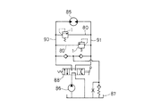
図8は、リリーフ弁装置1が用いられる流体圧回路の一例を示す流体圧回路図である。図8では、リリーフ弁装置1を簡略化した記号で示す。たとえば前述のように、建設機械または産業機械で旋回台を旋回するために用いられえる流体圧回路は、流体圧モータ85と、供給源を構成するポンプ86およびタンク87と、切換弁88とを有する。この流体圧回路では、切換弁88の操作によって、2つの入出力流路90,91のいずれか一方によって流体圧モータ85に作動流体を供給し、いずれか他方によって作動流体がタンク87に戻され、流体圧モータ85が回転される。このような流体圧回路において、流体圧モータ85への作動流体の供給を開始した直後および流体圧モータ85への作動流体の供給を停止した直後などに、流体圧モータ85の慣性によって、各入出力流路90,91内の作動流体の圧力が高くなる。この圧力の高騰を防ぐために、各入出力流路90,91間に1つのバイパス流路(図1に合せて同一の符号とする)80が設られ、このバイパス流路80に、二次側を向かい合せるようにして2つのリリーフ弁装置1が設けられ、各リリーフ弁装置1間において、バイパス流路80がタンク87に接続されている。このような構成によって、流体圧回路内の作動流体の圧力が高くなり過ぎることを防ぐことができる。
FIG. 8 is a fluid pressure circuit diagram showing an example of a fluid pressure circuit in which the relief valve device 1 is used. In FIG. 8, the relief valve device 1 is indicated by a simplified symbol. For example, as described above, a fluid pressure circuit that can be used to turn a swivel base in a construction machine or an industrial machine includes a
図9は、リリーフ弁装置1が用いられる流体圧回路の他の例を示す流体圧回路図である。図9では、リリーフ弁装置1を簡略化した記号で示す。図8に示す回路構成と異なる回路構成についてだけ説明する。図8の構成では、1つのバイパス流路80に向かい合うように2つのリリーフ弁装置1が設けられたけれども、図9の構成では、各入出力流路90,91間に、2つのバイパス通路80が設けられ、各バイパス流路80に、リリーフ弁装置1が互いに異なる向きでそれぞれ設けられる。このような構成でも、流体圧回路内の作動流体の圧力が高くなり過ぎることを防ぐことができる。
FIG. 9 is a fluid pressure circuit diagram showing another example of a fluid pressure circuit in which the relief valve device 1 is used. In FIG. 9, the relief valve device 1 is indicated by a simplified symbol. Only a circuit configuration different from the circuit configuration shown in FIG. 8 will be described. In the configuration of FIG. 8, two relief valve devices 1 are provided so as to face one
図10は、本発明の実施の他の形態のリリーフ弁装置1Aの一部を拡大して示す断面図である。本実施の形態のリリーフ弁装置1Aは、図1〜図9の実施の形態のリリーフ弁装置1と類似しており、対応する部分に同一の符号を付し、異なる構成についてだけ説明する。本実施の形態では、変形量調整ピストン6には、軸線方向2カ所に係止部51が形成され、ロッド17には、軸線方向の2カ所に係止片55が設けられている。一方のカ所に設けられる係止片55は、変形量調整ピストン6が第1の制限位置45a(図10の実線で示す位置)にある場合に、一方のカ所に形成される係止部51を係止し、他方のカ所に設けられる係止片55は、変形量調整ピストン6が第1の制限位置45aとは異なる第2の制限位置45b(図10の仮想線で示す位置)にある場合に、他方のカ所に形成される係止部51を係止することができる。第1および第2の制限位置45a,45bは、ともにそれぞれ制限位置45である。
FIG. 10 is an enlarged cross-sectional view showing a part of a relief valve device 1A according to another embodiment of the present invention. The relief valve device 1A of the present embodiment is similar to the relief valve device 1 of the embodiment of FIGS. 1 to 9, and corresponding portions are denoted by the same reference numerals, and only different configurations will be described. In the present embodiment, the deformation
各係止片55は、ロッド17に密に摺動可能に設けられるパイロット操作部材100を介して、パイロット圧力Ppに基づく流体圧駆動力で突出方向C1へ押圧されるように構成されている。また一方のカ所に設けられる係止片55と、他方のカ所に設けられる係止片55とは、個別に、かつ選択的に、パイロット圧力Ppに基づく流体圧駆動力で駆動することができる。パイロット圧力Ppが導かれていない状態では、係止片55は、変位量調整ピストン6によって押圧されて退避方向C2へ変位する。このような構成によって、複数カ所の制限位置を設けることができる。これによって最大リリーフ圧力Psを、3段階以上に設定することができる。図10の構成では、2カ所の制限位置によって3段階の最大リリーフ圧力Ps設定が可能である。
Each locking
図1〜図9に示すように、制限位置は、1つであってもよいが、図10に示すように複数であってもよい。制限位置が1つ場合、最大リリーフ圧力Psを2段階に設定することができる。制限位置が複数である場合、その数に応じて3段階以上に最大リリーフ圧力Psを設定することができる。 As shown in FIGS. 1 to 9, the restriction position may be one, but may be plural as shown in FIG. 10. When there is one limit position, the maximum relief pressure Ps can be set in two stages. When there are a plurality of restriction positions, the maximum relief pressure Ps can be set in three or more stages according to the number of restriction positions.
前述の実施の形態は、本発明の例示に過ぎず、本発明の範囲内に構成を変更することができる。たとえば変形量調整ピストンの変位を制限する構成は、前述の構成に限定されることはなく、他の構成であってもよい。また流体は、作動油に限定されるものではないし、建設機械または産業機械以外に設けられるリリーフ弁装置として実施されてもよい。 The above-described embodiment is merely an example of the present invention, and the configuration can be changed within the scope of the present invention. For example, the configuration for limiting the displacement of the deformation amount adjusting piston is not limited to the above-described configuration, and may be another configuration. Further, the fluid is not limited to hydraulic oil, and may be implemented as a relief valve device provided other than construction machinery or industrial machinery.
1 リリーフ弁装置
2 弁通路
3 ハウジング
4 プランジャ
5 圧力設定ばね部材
6 変形量調整ピストン
7 変位制限手段
11 一次ポート
12 二次ポート
51 係止部
55 係止片
56 パイロットピストン
57 安定ばね部材
78 係止面
DESCRIPTION OF SYMBOLS 1
Claims (5)
弁通路を閉じる閉位置と、弁通路を最大開度で開く全開位置とにわたって、開度を大きくする開方向および開度を小さくする閉方向へ変位可能に設けられ、一次圧力に基づく流体圧駆動力を開方向へ受ける弁体と、
弾性回復力によって、弁体を閉方向へ押圧するばね手段と、
ばね手段を支持し、ばね手段の変形量が最小となる最小位置と、ばね手段の変形量が最大となる最大位置とにわたって、変形量を大きくする変形方向および変形量を小さくする回復方向へ変位可能に設けられ、一次圧力に基づく流体圧駆動力を変形方向へ受ける変形量調整手段と、
変形量調整手段の変位を全許容する許容状態と、変形量調整手段の変位を制限する制限状態とに、切換え操作可能に設けられ、制限状態では、変形量調整手段が最小位置と最大位置との間に設定される制限位置を超えて最大位置側に変位することを阻止する変位制限手段とを含むことを特徴とするリリーフ弁装置。 A housing in which a valve passage is formed;
Fluid pressure drive based on the primary pressure, which is displaceable in the opening direction that increases the opening and the closing direction that decreases the opening over the closed position that closes the valve passage and the fully open position that opens the valve passage at the maximum opening A valve body that receives force in the opening direction;
Spring means for pressing the valve body in the closing direction by elastic recovery force;
The spring means is supported and displaced in the deformation direction in which the amount of deformation is increased and the recovery direction in which the amount of deformation is reduced over the minimum position where the amount of deformation of the spring means is minimum and the maximum position where the amount of deformation of the spring means is maximum. A deformation amount adjusting means that is provided in a deformable direction and receives a fluid pressure driving force based on the primary pressure in the deformation direction;
A switching operation is provided between a permissible state in which the displacement of the deformation amount adjusting means is completely allowed and a restricted state in which the displacement of the deformation amount adjusting means is restricted. In the restricted state, the deformation amount adjusting means has a minimum position and a maximum position. And a displacement limiting means for preventing displacement to a maximum position side beyond a limit position set between the relief valve device and the relief valve device.
変位制限手段は、変形量調整手段の変位に伴う係止部を係止する突出位置と、突出位置から退避した退避位置とにわたって、突出位置に向かう突出方向および退避位置に向かう退避方向へ変位可能に設けられ、パイロット流体の供給および供給停止によって、係止部を係止可能な状態と係止不可能な状態に駆動される係止片を有することを特徴とする請求項2記載のリリーフ弁装置。 The deformation amount adjusting means has a locking portion protruding in a direction intersecting the deformation direction and the recovery direction,
The displacement limiting means can be displaced in the protruding direction toward the protruding position and in the retracting direction toward the retracted position over the protruding position for locking the locking portion accompanying the displacement of the deformation amount adjusting means and the retracted position retracted from the protruding position. 3. A relief valve according to claim 2, further comprising a locking piece that is driven to a state where the locking portion can be locked and a state where the locking portion cannot be locked by supplying and stopping the supply of pilot fluid. apparatus.
Priority Applications (1)
| Application Number | Priority Date | Filing Date | Title |
|---|---|---|---|
| JP2004096831A JP4018659B2 (en) | 2004-03-29 | 2004-03-29 | Relief valve device |
Applications Claiming Priority (1)
| Application Number | Priority Date | Filing Date | Title |
|---|---|---|---|
| JP2004096831A JP4018659B2 (en) | 2004-03-29 | 2004-03-29 | Relief valve device |
Publications (2)
| Publication Number | Publication Date |
|---|---|
| JP2005282699A JP2005282699A (en) | 2005-10-13 |
| JP4018659B2 true JP4018659B2 (en) | 2007-12-05 |
Family
ID=35181328
Family Applications (1)
| Application Number | Title | Priority Date | Filing Date |
|---|---|---|---|
| JP2004096831A Expired - Fee Related JP4018659B2 (en) | 2004-03-29 | 2004-03-29 | Relief valve device |
Country Status (1)
| Country | Link |
|---|---|
| JP (1) | JP4018659B2 (en) |
Families Citing this family (5)
| Publication number | Priority date | Publication date | Assignee | Title |
|---|---|---|---|---|
| JP5320120B2 (en) * | 2009-03-26 | 2013-10-23 | ナブテスコ株式会社 | Multifunctional relief valve and emergency hydraulic power unit for aircraft equipped with the same |
| JP6635261B2 (en) * | 2016-01-29 | 2020-01-22 | 株式会社不二越 | Relief valve |
| KR102151124B1 (en) * | 2018-12-19 | 2020-09-02 | 주식회사 두산 | Relief valve apparatus |
| JP7142602B2 (en) * | 2019-04-20 | 2022-09-27 | 川崎重工業株式会社 | relief valve |
| JP2023104377A (en) * | 2022-01-17 | 2023-07-28 | 川崎重工業株式会社 | relief valve |
-
2004
- 2004-03-29 JP JP2004096831A patent/JP4018659B2/en not_active Expired - Fee Related
Also Published As
| Publication number | Publication date |
|---|---|
| JP2005282699A (en) | 2005-10-13 |
Similar Documents
| Publication | Publication Date | Title |
|---|---|---|
| JP5523518B2 (en) | Fuel injection valve with pressure balance type control valve | |
| JP4602335B2 (en) | Pressure supply valve | |
| JP5483567B2 (en) | Relief valve with relief pressure change function | |
| JP4930428B2 (en) | Bleed solenoid valve | |
| US20040256012A1 (en) | Pressure regulating valve in particular proportional pressure regulating valve | |
| KR20180071261A (en) | Fluid control valve | |
| JP6674799B2 (en) | Fuel injection valve and control device for fuel injection valve | |
| WO2020217981A1 (en) | Relief valve | |
| JP4018659B2 (en) | Relief valve device | |
| WO2019216195A1 (en) | Valve device | |
| JP2010101336A (en) | Spool valve | |
| US11168808B2 (en) | Valve device for controlling media flows of any type | |
| WO2016056564A1 (en) | Fluid pressure control device | |
| JP4801375B2 (en) | Air operated valve | |
| KR100965041B1 (en) | Actuator control device | |
| JP5561528B2 (en) | Relief valve with relief pressure change function | |
| JP6850220B2 (en) | Spool valve | |
| US9772039B2 (en) | Hydraulic pressure control valve | |
| JP4463028B2 (en) | Spool valve | |
| JP2018053931A (en) | Shockless relief valve | |
| JP2004197943A (en) | Cylinder piston device | |
| KR20170078147A (en) | Leakage prevention structure for remote control valve | |
| KR101192166B1 (en) | Solenoid valve | |
| JP2016176567A (en) | Fluid pressure cylinder | |
| JP7346037B2 (en) | flow control valve |
Legal Events
| Date | Code | Title | Description |
|---|---|---|---|
| A977 | Report on retrieval |
Free format text: JAPANESE INTERMEDIATE CODE: A971007 Effective date: 20070911 |
|
| TRDD | Decision of grant or rejection written | ||
| A01 | Written decision to grant a patent or to grant a registration (utility model) |
Free format text: JAPANESE INTERMEDIATE CODE: A01 Effective date: 20070918 |
|
| A61 | First payment of annual fees (during grant procedure) |
Free format text: JAPANESE INTERMEDIATE CODE: A61 Effective date: 20070920 |
|
| R150 | Certificate of patent or registration of utility model |
Free format text: JAPANESE INTERMEDIATE CODE: R150 |
|
| FPAY | Renewal fee payment (event date is renewal date of database) |
Free format text: PAYMENT UNTIL: 20100928 Year of fee payment: 3 |
|
| FPAY | Renewal fee payment (event date is renewal date of database) |
Free format text: PAYMENT UNTIL: 20110928 Year of fee payment: 4 |
|
| S111 | Request for change of ownership or part of ownership |
Free format text: JAPANESE INTERMEDIATE CODE: R313111 |
|
| FPAY | Renewal fee payment (event date is renewal date of database) |
Free format text: PAYMENT UNTIL: 20110928 Year of fee payment: 4 |
|
| R350 | Written notification of registration of transfer |
Free format text: JAPANESE INTERMEDIATE CODE: R350 |
|
| FPAY | Renewal fee payment (event date is renewal date of database) |
Free format text: PAYMENT UNTIL: 20110928 Year of fee payment: 4 |
|
| FPAY | Renewal fee payment (event date is renewal date of database) |
Free format text: PAYMENT UNTIL: 20120928 Year of fee payment: 5 |
|
| FPAY | Renewal fee payment (event date is renewal date of database) |
Free format text: PAYMENT UNTIL: 20120928 Year of fee payment: 5 |
|
| FPAY | Renewal fee payment (event date is renewal date of database) |
Free format text: PAYMENT UNTIL: 20130928 Year of fee payment: 6 |
|
| FPAY | Renewal fee payment (event date is renewal date of database) |
Free format text: PAYMENT UNTIL: 20140928 Year of fee payment: 7 |
|
| LAPS | Cancellation because of no payment of annual fees |