JP4018566B2 - Broadband Raman amplifier - Google Patents
Broadband Raman amplifier Download PDFInfo
- Publication number
- JP4018566B2 JP4018566B2 JP2003072205A JP2003072205A JP4018566B2 JP 4018566 B2 JP4018566 B2 JP 4018566B2 JP 2003072205 A JP2003072205 A JP 2003072205A JP 2003072205 A JP2003072205 A JP 2003072205A JP 4018566 B2 JP4018566 B2 JP 4018566B2
- Authority
- JP
- Japan
- Prior art keywords
- pumping
- optical fiber
- wavelength
- wavelengths
- pump
- Prior art date
- Legal status (The legal status is an assumption and is not a legal conclusion. Google has not performed a legal analysis and makes no representation as to the accuracy of the status listed.)
- Expired - Fee Related
Links
- 238000001069 Raman spectroscopy Methods 0.000 title claims description 46
- 238000005086 pumping Methods 0.000 claims description 96
- 239000013307 optical fiber Substances 0.000 claims description 32
- VYPSYNLAJGMNEJ-UHFFFAOYSA-N Silicium dioxide Chemical compound O=[Si]=O VYPSYNLAJGMNEJ-UHFFFAOYSA-N 0.000 claims description 24
- 239000000835 fiber Substances 0.000 claims description 24
- 239000000377 silicon dioxide Substances 0.000 claims description 12
- 230000003321 amplification Effects 0.000 claims description 9
- 238000003199 nucleic acid amplification method Methods 0.000 claims description 9
- 230000003287 optical effect Effects 0.000 claims description 5
- 229910052732 germanium Inorganic materials 0.000 claims 1
- GNPVGFCGXDBREM-UHFFFAOYSA-N germanium atom Chemical compound [Ge] GNPVGFCGXDBREM-UHFFFAOYSA-N 0.000 claims 1
- 230000005540 biological transmission Effects 0.000 description 19
- 238000013459 approach Methods 0.000 description 15
- 238000000034 method Methods 0.000 description 11
- 230000009931 harmful effect Effects 0.000 description 10
- 230000008901 benefit Effects 0.000 description 9
- 238000010586 diagram Methods 0.000 description 9
- 239000006185 dispersion Substances 0.000 description 7
- 230000003993 interaction Effects 0.000 description 7
- 230000000694 effects Effects 0.000 description 6
- 230000008569 process Effects 0.000 description 5
- 239000000463 material Substances 0.000 description 4
- 230000009022 nonlinear effect Effects 0.000 description 4
- 238000004458 analytical method Methods 0.000 description 3
- 238000001228 spectrum Methods 0.000 description 3
- 238000012546 transfer Methods 0.000 description 3
- 238000004891 communication Methods 0.000 description 2
- 238000012986 modification Methods 0.000 description 2
- 230000004048 modification Effects 0.000 description 2
- 239000004065 semiconductor Substances 0.000 description 2
- 235000012239 silicon dioxide Nutrition 0.000 description 2
- YCKRFDGAMUMZLT-UHFFFAOYSA-N Fluorine atom Chemical compound [F] YCKRFDGAMUMZLT-UHFFFAOYSA-N 0.000 description 1
- 229910000530 Gallium indium arsenide Inorganic materials 0.000 description 1
- OAICVXFJPJFONN-UHFFFAOYSA-N Phosphorus Chemical compound [P] OAICVXFJPJFONN-UHFFFAOYSA-N 0.000 description 1
- 238000010521 absorption reaction Methods 0.000 description 1
- 239000011248 coating agent Substances 0.000 description 1
- 238000000576 coating method Methods 0.000 description 1
- 229910052681 coesite Inorganic materials 0.000 description 1
- 229910052906 cristobalite Inorganic materials 0.000 description 1
- 230000001419 dependent effect Effects 0.000 description 1
- 238000013461 design Methods 0.000 description 1
- 230000008030 elimination Effects 0.000 description 1
- 238000003379 elimination reaction Methods 0.000 description 1
- 238000005516 engineering process Methods 0.000 description 1
- 238000002474 experimental method Methods 0.000 description 1
- 229910052731 fluorine Inorganic materials 0.000 description 1
- 239000011737 fluorine Substances 0.000 description 1
- 239000011521 glass Substances 0.000 description 1
- 239000012535 impurity Substances 0.000 description 1
- 230000009021 linear effect Effects 0.000 description 1
- 238000005259 measurement Methods 0.000 description 1
- 230000007246 mechanism Effects 0.000 description 1
- 229910052698 phosphorus Inorganic materials 0.000 description 1
- 239000011574 phosphorus Substances 0.000 description 1
- 229920000642 polymer Polymers 0.000 description 1
- 239000011253 protective coating Substances 0.000 description 1
- 230000002040 relaxant effect Effects 0.000 description 1
- 229910052594 sapphire Inorganic materials 0.000 description 1
- 239000010980 sapphire Substances 0.000 description 1
- 238000010187 selection method Methods 0.000 description 1
- 238000000926 separation method Methods 0.000 description 1
- 239000007787 solid Substances 0.000 description 1
- 229910052682 stishovite Inorganic materials 0.000 description 1
- 238000010408 sweeping Methods 0.000 description 1
- 230000001360 synchronised effect Effects 0.000 description 1
- 229910052905 tridymite Inorganic materials 0.000 description 1
Images


Classifications
-
- H—ELECTRICITY
- H04—ELECTRIC COMMUNICATION TECHNIQUE
- H04B—TRANSMISSION
- H04B10/00—Transmission systems employing electromagnetic waves other than radio-waves, e.g. infrared, visible or ultraviolet light, or employing corpuscular radiation, e.g. quantum communication
- H04B10/29—Repeaters
- H04B10/291—Repeaters in which processing or amplification is carried out without conversion of the main signal from optical form
- H04B10/2912—Repeaters in which processing or amplification is carried out without conversion of the main signal from optical form characterised by the medium used for amplification or processing
- H04B10/2916—Repeaters in which processing or amplification is carried out without conversion of the main signal from optical form characterised by the medium used for amplification or processing using Raman or Brillouin amplifiers
-
- H—ELECTRICITY
- H01—ELECTRIC ELEMENTS
- H01S—DEVICES USING THE PROCESS OF LIGHT AMPLIFICATION BY STIMULATED EMISSION OF RADIATION [LASER] TO AMPLIFY OR GENERATE LIGHT; DEVICES USING STIMULATED EMISSION OF ELECTROMAGNETIC RADIATION IN WAVE RANGES OTHER THAN OPTICAL
- H01S3/00—Lasers, i.e. devices using stimulated emission of electromagnetic radiation in the infrared, visible or ultraviolet wave range
- H01S3/30—Lasers, i.e. devices using stimulated emission of electromagnetic radiation in the infrared, visible or ultraviolet wave range using scattering effects, e.g. stimulated Brillouin or Raman effects
- H01S3/302—Lasers, i.e. devices using stimulated emission of electromagnetic radiation in the infrared, visible or ultraviolet wave range using scattering effects, e.g. stimulated Brillouin or Raman effects in an optical fibre
-
- H—ELECTRICITY
- H04—ELECTRIC COMMUNICATION TECHNIQUE
- H04B—TRANSMISSION
- H04B10/00—Transmission systems employing electromagnetic waves other than radio-waves, e.g. infrared, visible or ultraviolet light, or employing corpuscular radiation, e.g. quantum communication
- H04B10/25—Arrangements specific to fibre transmission
- H04B10/2507—Arrangements specific to fibre transmission for the reduction or elimination of distortion or dispersion
- H04B10/2543—Arrangements specific to fibre transmission for the reduction or elimination of distortion or dispersion due to fibre non-linearities, e.g. Kerr effect
- H04B10/2563—Four-wave mixing [FWM]
-
- H—ELECTRICITY
- H01—ELECTRIC ELEMENTS
- H01S—DEVICES USING THE PROCESS OF LIGHT AMPLIFICATION BY STIMULATED EMISSION OF RADIATION [LASER] TO AMPLIFY OR GENERATE LIGHT; DEVICES USING STIMULATED EMISSION OF ELECTROMAGNETIC RADIATION IN WAVE RANGES OTHER THAN OPTICAL
- H01S3/00—Lasers, i.e. devices using stimulated emission of electromagnetic radiation in the infrared, visible or ultraviolet wave range
- H01S3/05—Construction or shape of optical resonators; Accommodation of active medium therein; Shape of active medium
- H01S3/06—Construction or shape of active medium
- H01S3/063—Waveguide lasers, i.e. whereby the dimensions of the waveguide are of the order of the light wavelength
- H01S3/067—Fibre lasers
- H01S3/06754—Fibre amplifiers
-
- H—ELECTRICITY
- H01—ELECTRIC ELEMENTS
- H01S—DEVICES USING THE PROCESS OF LIGHT AMPLIFICATION BY STIMULATED EMISSION OF RADIATION [LASER] TO AMPLIFY OR GENERATE LIGHT; DEVICES USING STIMULATED EMISSION OF ELECTROMAGNETIC RADIATION IN WAVE RANGES OTHER THAN OPTICAL
- H01S3/00—Lasers, i.e. devices using stimulated emission of electromagnetic radiation in the infrared, visible or ultraviolet wave range
- H01S3/09—Processes or apparatus for excitation, e.g. pumping
- H01S3/091—Processes or apparatus for excitation, e.g. pumping using optical pumping
- H01S3/094—Processes or apparatus for excitation, e.g. pumping using optical pumping by coherent light
- H01S3/094096—Multi-wavelength pumping
Description
【0001】
【発明の属する技術分野】
本発明は一般にラマン増幅器に関し、さらに詳細には、波長の広い帯域にわたって平坦なゲインを備えた分布型ラマン増幅器に関する。
【0002】
【従来の技術】
光伝送システムは、光ファイバ伝送回線、典型的には長距離伝送回線の情報の取り扱い量を増加させるために、波長分割多重(WDM)を採用している。初期のWDMシステムは、しばしばCバンドと呼ばれる1550ナノメートル(nm)に中心を持つ、例えば、1530〜1565nmの比較的狭い波長帯域を使用して動作していた。これは、シリカを主成分とした標準的な光ファイバが、最も適した低い吸収を有する波長領域である。
【0003】
ほとんどのWDMシステムにおいて、システムが収容できるチャンネル数とチャンネル分離とは引き替えとなっていた。どちらの目的にとっても、広い動作周波数帯域、すなわち、広い範囲の動作波長が好ましいものである。
【0004】
最近、Cバンドの伝送帯域のはるか上方に有効動作波長範囲を広げたシステムが設計された。波長に関しては、Lバンドと呼ばれる新しい帯域が様々に規定されているが、本説明の目的のためには、これは1570〜1610nmである。これらの付加的な波長の使用は、WDMシステムの能力を実質的に拡大している。有効動作波長の枠(window)を1610nm以上、例えば、1620nmにさらに拡大するために、現在も努力が重ねられている。これらの努力の成否は、構成要素、例えば、この広い波長範囲にわたって有効な動作を提供する増幅器を見出すことにかかっている。
【0005】
WDMシステムにおいては、WDM波長帯域全体にわたって均一なゲインを有することが重要である。この目的は、動作波長範囲がさらに長い波長に拡大されるに従って、達成することがさらに困難になる。最近、ラマン散乱を使用する新しいタイプの光ファイバ増幅器が開発されている。これらの中で最も優れたものは、進行波増幅器として通常の伝送の全長(span)にわたって動作する分布型増幅器である。ラマン散乱は、媒体に入射した光が、入射光より低い周波数の光に変換される過程である。ポンピング・フォトンが分子を仮想準位(非共鳴状態)にまで励起する。分子の状態は、それより低いエネルギー準位に素早く減衰し、この過程で信号フォトンを放射する。ポンピング・フォトンが仮想準位に励起されているため、ラマン・ゲインは、いかなる波長のポンピング・ソースに対しても発生する。ポンピング・フォトンと信号フォトンとの間のエネルギーの差は、ホスト材料の各分子振動によって散失される。これらの振動準位は、ラマン・ゲイン曲線の周波数シフトおよび形状を決定する。ポンピング・フォトンと信号フォトンとの間の周波数(または、波長)の差は、ストークス・シフトと呼ばれる。Geをドープしたシリカ・ファイバにおいて、ゲインの最大値が得られるストークス・シフトは、13テラヘルツ(THz)程度である。シリカの非晶質性によって、ラマン・ゲイン曲線は、光ファイバにおいて、かなり広いものになる。
【0006】
ラマン散乱はいかなる波長においても発生し得るため、この散乱は、信号を増幅するためにいくつかの異なった波長のラマン・ポンピングを使用することによって、複数の信号波長を含む通信システムに利益をもたらすために利用することができる。特定の波長で見られるゲインは、ラマン散乱によるポンプ間のエネルギーの転送を考慮した全てのポンプによって提供されるゲインを重ね合わせたものである。各ラマン・ポンピング波長において供給されるパワーに適切に重み付けすることによって、異なった信号波長によって見られるゲイン間に小さな差(この差はゲイン・リプルまたはゲイン・フラットネスと呼ばれる)がある信号ゲイン対波長プロファイルを得ることが可能になる。
【0007】
【発明が解決しようとする課題】
ポンプの多重性は多くの異なった実験に使用され、成功を収めてきた。しかし、この手法には1つの長年続く問題がある。それは、時々、四波混合(FWM)と呼ばれる有害な非線形効果が発生することである。通信システムにおいて、信号帯域内でFWMが発生すると、伝送エラーをもたらすことがある。多重ポンピング波長ラマン増幅方式においては、ポンプ数が増加するに従ってFWMの可能性は増加する。
【0008】
四波混合の有害な効果が理解されている。最近、これらの効果の低減に向けた1つの手法が提案された(EP 1 148 666A2)。この手法において、各ポンピング波長は、一緒に時間分割多重(TDM)されているか、または、ポンピング・ソースの周波数が変調(FM)されている。様々なポンピング波長がファイバに沿った短い距離のみにわたって重なっているため、ポンピング波長間のFWMは排除されるか、または、大幅に低減されなければならない。
【0009】
この手法がFWMを排除する一方、このシステムにおける定格ポンピング・パワーの要件は比較的高度である。さらに、TDMを行なうために、一部が比較的大きなパワーで動作する比較的大きな数のポンピング波長が、システムのコストを大幅に上昇させている。これらの要件のいずれをも軽減することは、有害なFWM効果を制御するために多重化ポンピング波長を使用することの魅力を大幅に強めるものである。加えて、C+Lバンドにわたって均一かつ平坦なゲインを作成することに効果的であるラマン増幅器は、DWDMシステムの設計における重要な技術的進歩を代表するものである。
【0010】
【課題を解決するための手段】
本発明は、FWM効果が全てのポンピング波長にわたっては均一でないことの理解に部分的に基づいている。発明者は、分布型ラマン増幅器のCおよびLバンドに平坦なラマン・ゲインを提供するために必要なポンプの波長およびパワーを解析した。この解析から、FWMの特に深刻化している場所には、特定のポンピング波長が特定された。以下に述べる例のポンプ・スペクトルにおける最も短い波長であるいくつかの波長は、FWMをほとんど、または、全くもたらさない。また、長い波長において必要とされるパワーが、短い波長におけるものより大幅に小さいことも観察された。これは、短い波長が伝送の全長において長い波長をポンピングするためである。この理解に従えば、FWMに寄与しているポンピング波長に対してのみTDMまたはFMを使用することによって,有害なFWMの排除を実現することができる。また、このTDMまたはFM方式は伝送の全長における短い波長による長い波長のポンピングを利用するため、この方法によって必要とされるパワーの大きさは低減される。長い波長は、常に低いラウンチ・パワー(launch power)を有する。結果は以下を含む。
1)より少ないTDMポンプによって、各ポンプに対するスイッチング要件、並びに、必要なピーク・パワーが低減される。
2)FMソースに必要な周波数範囲が削減される。
3)変調するためのポンプが少なくなり、電子回路の総コストが下がる。
4)ポンプ多重化のために必要な周波数範囲を狭くすることによって、掃引波長ソース(swept wavelength source)に対する要求が削減され、この選択肢をより魅力的かつ実行しやすいものにしている。
【0011】
【発明の実施の形態】
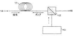
図1を参照すると、示す配置は、最も典型的には光ファイバである伝送の全長11を備えた分布型ラマン光ファイバ増幅器の構造を表す。伝送の全長11は、典型的には1km以上の実質的な長さのファイバを表す。当業者には、本説明における図が一定の縮尺では描かれていず、各要素が模式的に示されていることが明らかである。説明の詳細を例示する目的のために、本発明の好ましい実施例、すなわち、増幅器媒体が通常の伝送の全長である分布型増幅器を示す。本発明の原理は集中型増幅器にも適用され、この場合、増幅媒体は専用の長さの光ファイバであるか、または、他の適切な進行波媒体である。11で示されるファイバの長さは、好ましくは、信号の増幅を生み出す光学的相互作用を考慮した少なくとも500mの長さである。増幅器は、12において模式的に示すカプラを介してファイバのコアに結合されるポンピング・ソース13によって図中に示すように、典型的に終端ポンピング(end pumped)されており、かつ、後方ポンピング(counter pumped)されている。典型的なポンピング波長は14XXnmであるが、他の波長でもよい。入力信号は14で示し、増幅された信号出力は16で示す。
【0012】
図2を参照すると、光ファイバの終端が示されている。この図は、ファイバに沿ったいかなる位置においても取られる断面の代表的なものである。ファイバは、コア21およびクラッド22を含む。ファイバのコアは、典型的にGeがドープされたシリカである。代わりに、これは、リンもしくは他の屈折率修正不純物、または、これらの組み合わせをドープすることもできる。クラッド層は、好ましくは、高純度シリカ材、すなわち、少なくとも純度85%のSiO2である。いくつかの好ましい構造において、これは、純粋なシリカまたはフッ素がドープされたシリカであってもよい。ファイバは、典型的にはポリマ・コーティングである保護コーティング23も有する。
【0013】
図2に示す構造の寸法は、実質的に変化してもよい。クラッド層の直径は、典型的には50〜400μmの範囲にあり、好ましくは70〜300μmである。コアの直径は、典型的に2〜12μmである。
【0014】
光ファイバ・ラマン増幅器は、シリカを主成分とする光ファイバ内に散乱した光が入射光の波長より短い波長を有するという原理で動作する。これは図3に模式的に示されており、ここで、ポンピング・フォトンνpは、分子を仮想準位(非共鳴状態)にまで励起する。分子は、低いエネルギー準位に減衰し、この過程中に信号フォトンνsを放射する。注意すべき重要な点は、ポンピング・フォトンが仮想準位に励起されるために、ラマン・ゲインが、いかなる波長においてもポンピング・ソースに対して発生することである。ポンピング・フォトンと信号フォトンの間のエネルギーの差は、ホスト材料の分子振動によって散失される。これらの振動準位は、ラマン・ゲイン曲線の周波数シフトおよび形状を決定する。ポンピング・フォトンと信号フォトンとの間の周波数(または、波長)の差は、ストークス・シフトと呼ばれる。Geをドープしたシリカ・ファイバにおいて、ゲインの最大値が得られるストークス・シフトは、13THz程度である。シリカの非晶質性によって、ラマン・ゲイン曲線は、光ファイバにおいてかなり広いものとなる。Geがドープされた光ファイバについての正規化されたラマン・ゲイン・スペクトルを、ポンプからの周波数シフトに関して図4に示す。
【0015】
複数の信号波長を含む電気通信システムにおいては、信号を増幅するためにいくつかの異なった波長のラマン・ポンプを使用することができる。なぜなら、ラマン散乱がいかなる波長においても発生し得るからである。特定の波長で見られるゲインは、ラマン散乱によるポンプ間のエネルギーの転送を考慮した全てのポンプによって提供されるゲインを重ね合わせたものである。各ラマン・ポンピング波長において供給されるパワーに適切に重み付けすることによって、異なった信号波長によって見られるゲイン間に小さな差がある信号ゲイン対波長のプロファイルを得ることが可能になる。この差はゲイン・リプルまたはゲイン・フラットネスと呼ばれ、(Gmax−Gmin)としてdBで表すことができる。
【0016】
平坦なゲインを発生するために設計された多重ポンプ・システムの例を図5に示す。長い波長において必要とされるパワーが、短い波長におけるものより大幅に小さいことに注意すべきである。WDMラマン増幅器におけるこの複数のポンプの配置の使用は、図6に示す出力WDM信号を発生し、同図では、比較的平坦なゲインがCおよびLバンドにわたって得られている。
【0017】
前述したように、複数のポンプの使用は、四波混合(FWM)の問題を導入する。四波混合は、1つまたは複数のフォトンが組み合わされ,別の周波数のフォトンを生成する時に発生する。新しい周波数は、総エネルギー量および運動量(位相マッチング)が保存されるように決定される。これの1つの可能性を図7に模式的に示す。本説明の流れにおいて、3つの波長νp1、νp2、および、νp3は、2つ以上の個々のポンピング波長に対応している。FWMが、ここに掲げる図においては3つのポンピング波長である3つの波長間の非線形相互作用からもたらされることに注目することが重要である。FWMは、2つのポンピング波長のみと、媒体中を進行する他のソースからの第3の波長とで発生することも可能である。
【0018】
電気通信システムにおいて、信号帯域におけるFWMからもたらされる疑似波長成分は伝送エラーを招くこともある。位相マッチング条件が自動的に満たされるラマン散乱とは異なり、FWMの効率は、周波数および屈折率の適切な選択に依存している。位相のミスマッチに対しては3つの寄与がある。すなわち、材料の分散、導波路の分散、および、ファイバの非線形性である。ファイバのゼロ分散波長(したがって、導波路の分散)の位置を操作することによって、非常に効率的なFWMを発生させることができる。実際には、これは、1つのポンピング波長をファイバの分散ゼロ付近に有すること、または、分散ゼロのそれぞれの側の波長を備えた2つのポンプを有することのいずれかになる。したがって、多重ポンピング波長ラマン増幅法におけるポンプ数が増加するに従い、FWMの可能性も増加することが明らかになる。
【0019】
FWM効果の低減に向けた効果的な手法は、複数のポンピング波長を時間分割多重化(TDM)することである。様々なポンピング波長がファイバに沿った小さな距離のみで重なり合うため、ポンピング波長間の相互作用から生じるFWMおよび他の有害な非線形効果は排除されるか、または、大幅に低減される。TDM多重ポンピング・ソースを図8に模式的に示す。それぞれ1480nm、1494nm、および、1508nmで動作するレーザ・ダイオード・ポンピング・ソース71、72、および、73は、一緒に同期され、74、75、および、76で示す分離されたタイム・スロットに多重化される。ポンピング・ソース71および72は、WDMコンバイナ81において組み合わされ、ポンピング・ソース73は、WDMコンバイナ82において71および72に加えられる。図8に示す手法は、FWMおよび他の有害な非線形効果の制御に役立つ一方、これにはいくつかの問題がある。
1)同じゲイン平坦度を維持するために、最初の大量のピーク・ポンピング・パワーが必要である。これは、他の有害な線形効果を招くことがある。
2)必要なTDMポンプの数が増加するに従い、スイッチング速度の要件も増加する。これは、必要なピーク・パワーも増大させる。
3)FMソースと同様。信号波長の範囲がさらに広がると、ソースが変調される速度と必要なパワーの双方が上昇する。
4)ダイオードを変調することは、それらを一定の出力で動作させるよりコストがかかる。TDM方式にとって、これは、ポンプに関連するコストが波長の数とともに増加することを意味する。
5)FM方式にとって、必要とされる周波数範囲が広いことは、そのようなソースを開発するための可能性に対する厳しい制約となっている。
【0020】
本発明によってこれらの条件を緩和することは、2つの重要な発見に従うものである。先ず、全てのポンプが有害なFWMに寄与している訳ではないこと。図9に示す1つの典型的な例では、FWMのメカニズムに関与しているのは、3つの最長波長のみである。この図は、1525〜1550nmの波長範囲における5つのWDMチャンネルについて、後方散乱エネルギー対波長(nm)の関係を示す。ここには2本の曲線があり、実線の曲線は信号のない後方散乱を表し、点線の曲線は信号の載せられた後方散乱を表す。ポンピング波長は、1445nm、1466nm、1480nm、1494nm、および、1508nmである。この図はCバンドの一部のみを含むが、C+Lバンドの他の部分は定性的に同様の効果を示す。解析は、約1527nmにおける後方散乱のピークが、ポンピング波長1508nm、1494nm、および、1480nmの間のFWMの結果であることを示す。図7を参照すると、これらは、それぞれνp1、νp2、および、νp3に対応する。1527nmにおけるピークは、νFWMに対応する。約1537nmにおけるピークは、νp1が1494nm、νp2が1480nm、および、νp3が1445nmであるFWMの結果である。約1540nmにおけるピークは、νp1が1508nm、νp2が1494nm、および、νp3が1466nmであるFWMの結果である。図7から、図9のFWMピークを発生させるためには、全ての3つのポンピング波長が必要であることが理解される。長い波長が3つのピーク全てについてのFWMの主な構成要素であるという認識が、本発明の1つの態様を導く。長い波長、すなわち、1480nm、1494nm、および、1508nmのみを多重化することによって、FWMに必要な全ての波長が同時に存在する時がないことが確実となる。したがって、TDM多重ポンピング・ソースの長所を得るためには、全ての多重ポンピング・ソースをTDMすることは必要ではない。適切に選択すれば、全てより少ないポンプを多重化すればよい。残りのポンプは、持続波(CW)で動作される。これらの原理に基づくシステムを図10に示す。これは、上記に列挙した要因に関して大幅な進歩をもたらす。全てより少ないポンピング・ソースを多重化することが必要であることが一度認識されれば、それらを選択することは単純明解である。図9に示唆される測定は、よく知られている原理に従っており、実験的に確認できる。
【0021】
同様の目的は、TDMの代替物、すなわち、周波数変調されたポンピング・ソースを使用することによっても達成できる。単一ソース・ダイオードで多重ポンピング波長を掃引することによって、1回に1つの波長のみが放射され、したがって、FWMに対する可能性を排除する。この手法は図11に示され、ここで、掃引周波数ソース91は、図8の複数のダイオード71〜73の代わりに使用されている。この手法は、いくつかの点で実施がさらに単純であるが、広帯域単一ソースは、図8のシステムのための構成要素ほどには十分に開発されていない。しかし、これらの構成要素が登場すれば、本発明のシステムは、効果的に、または、FM手法についてはさらに効果的にさえ実施することができる。掃引波長ソースに必要な波長範囲が本発明の原理を使用して削減されることを指摘することは重要である。例えば、図10(FM)および図11の掃引ダイオードが1480〜1508nmの波長範囲にわたって動作できる一方、1420〜1480nmの範囲において動作する残りのポンプは、CWで動作する個々のダイオードである。
【0022】
信号チャンネルが変調されたポンプを通過するため、複数ポンプ多重化技術は、逆伝播構成において効果的である。もし、削減された相互作用の長さを補償するために、ポンプのパワーが増大されたなら、光路平均されたラマン・ゲインは一定となる。全ての異なるポンピング波長を通じてTDMまたはFMソースが循環する速度も、信号パワーのゲイン依存変調が生じないように、十分に速くなければならない。ポンプから信号への雑音の転送に関する過去の研究は、全てのポンピング波長についての全体的な反復速度が50kHzを上回るべきであることを示唆している。したがって、各波長は約n倍速く変調され、ここでnは波長の数である。変調速度および必要なピーク・パワーは関連していることに注意すべきである。変調速度が速くなるほど、特定の波長において必要なピーク・パワーが大きくなる。
【0023】
これらの解析を行なううえで、長い波長で必要とされるポンプ・パワーは、短い波長におけるものより大幅に小さいことも認識された。これは、ラマン・ポンプの波長が短くなるほど、伝送の全長における波長は長くなるためである。したがって、パワーの点から、これは、長いポンピング波長におけるTDMまたはFMを使用することのみによって有害なFWMの排除を許容可能とする。多重化されたソース全体を完全に均等化するためには、個々のポンピング波長に対するレーザ・ダイオード・ソースが、不均等なパワーを供給するように同調されることが実際には必要となる。これは、長い波長ソースに対するパワー要件を低減し、TDMポンピング・ソースに含まれるポンプ・パワー全体も低減する。ポンプ・パワー全体を低減することは、当技術分野においてよく知られているシステムのいくつかの重要な長所を有することが可能となる。
【0024】
個々のポンプ間でのラマン・エネルギー交換の恩恵を得るためには、相互作用の長さが実質的なもの、すなわち、1km以上であることを必要とする。この長さは、分布型モードで動作する伝送の全長(典型的には1kmを越える、すなわち、3〜100km)を表してもよく、または、離散増幅器デバイスに使用される光ファイバの長さであってもよい。
【0025】
要約すれば、多重化ポンピング・ソースの数を削減することは、以下の長所を有する。
1)本発明が伝送の全長において短い波長による長い波長のポンピングを利用しているため、本発明の選択的ポンピング・ソース多重化によって必要とされるパワーの大きさは削減される。長い波長は、既に低いラウンチ・パワーを有している。
2)多重化の量を削減することによって、各ポンプに必要とされるスイッチング速度および必要なピーク・パワーが低減される。
3)FMソースに必要とされる周波数範囲が低減される。
4)変調するためのポンプ数が少なくなったため、電子回路の総コストが低下する。
5)周波数範囲を狭くすることによって、掃引波長ソースの開発に向けた手法の数が増加する。
【0026】
従来技術の手法では、多重ポンプ・システムにおける全てのポンプが多重化されており、個々のポンプの間ではエネルギーのラマン交換はない。上記に示すように、これらの相互作用は、長い波長、すなわち、短い波長によってラマン・ポンピングされるもののために必要なポンプ・パワーの低減に役立てることができる。今述べた本手法の改変は、多重TDMまたはFM変調のパターンを使用することである。基本的に、この手法は上記に述べた認識に基づくが、多重化されたポンプ信号に対する異なった選択方法を使用している。これは、利益をもたらし、さらに、FWM効果を低減または排除するために、個々のポンピング・ソース間のラマン相互作用をデバイス設計者が使用することを可能にする。これを、図12および13に模式的に示す。この例示的システムにおいては、4つのポンピング波長が使用されている。四波混合の各成分は、λ1+λ2+λ3およびλ1+λ2+λ4の組み合わせによって発生される。もしλ1とλ3におけるポンプの変調が重なり合い、かつ、λ2とλ4におけるポンプの変調が重なり合っていれば、全ての有害なFWMは排除できる。この変調方式を図13に示す。加えて、伝送の全長において、λ1におけるポンプはそれでもλ3におけるポンプを増幅でき、λ2におけるポンプはλ3におけるポンプをポンピングできる。同じ手法は、2つのFMソースに対しても使用でき、ここでは、1つのソースがλ1からλ2まで掃引する一方、別のソースがλ3からλ4まで掃引する。いずれの場合においても、伝送ファイバは、時間変化ポンピング・ソースを増幅するために有利に使用される。
【0027】
TDMまたはFMポンピング・ソースのための増幅器として、伝送の全長を使用するという概念は、複数次のポンプを使用することに拡張できる。この手法の長所は、最近、米国特許第6,163,630号において指摘された。複数次ラマン・ポンピングにおいて、信号光は、ポンピング光の最大ゲイン周波数から1.5ストークス・シフト大きい。第2次ポンピングにおける例として、信号光から1ストークス・シフト離れた第1次ストークス・ポンプをポンピングするために、信号光から2ストークス・シフト離れたポンピング波長が使用される。図14および15に、これを示す。2つの構成を示す。第1の場合の図14では、第1次および第2次の双方のポンプとも、信号光に比較して後方ポンピングされている。第2次ポンプが第1次ポンプに変換されるためには、有限の長さのファイバを必要とする。したがって、第1次ポンプが信号をポンピングする。したがって、これは、ファイバの信号入力端の近くで信号増幅することを可能にする。この手法の第2の実施例において、第2次ポンプは、信号と同じ方向に進行し(前方ポンピング(co-pumped)される)(図15)、第1次ポンプは後方ポンピングされる。第2次ポンプは、ファイバの入力端において第1次ポンプをポンピングし、これは、第1次ポンプが信号をポンピングすることを可能にする。次に、これは、ラマン・ゲインが、ファイバの信号入力端の近くで起きることを可能にする。第1次ラマン・ポンピングにおいて、ポンプは一般的に信号とは逆方向に進行するため、複数次ポンピングは有利である。増幅のほとんどは、伝送の全長の信号出力端の近くで起こる。ファイバのこの場所では、信号パワーが既に大幅に劣化している。もしファイバ内に見られるラマン・ゲインがファイバの信号入力端の近くで起こることが可能であれば、改善された信号対雑音比(SNR)および雑音指数(NF)が得られる。第2次ポンプのために必要なパワーは、かなり小さい。複次ポンピングされたシステムの一例において、1366/1455nmに対するパワー比は、それぞれ970/10mWであった。1455nmにおけるこのような小さなパワーを使用すると、この手法も、低いパワー要件を利用することによって、CW−TDMまたはCW−FM方式を使用するために理想的に見える。
【0028】
本来はFWMを軽減する手段として考えられたが、本発明には、いくつかの付加的な長所がある。さらに広い帯域幅にわたって動作を拡大するために、現行のシステムを更新することを希望する場合、大幅にコストが削減できる。現在のポンプの全てを交換する代わりに、変調できるいくつかの付加的なポンプを追加することのみが必要となる。ポンプ・パターンおよび/またはパワー準位を操作することによっても、いくつかのチャンネルにわたるゲインの平坦性に対するある程度の制御を得ることができる。これは、異なったゲイン・プロファイルの形状を考慮するものである。加えて、FWMまたはスーパーコンティニューム(supercontinuim)の発生などの非線形効果は、ファイバのゼロ分散波長付近におけるポンプの選択的変調を可能とすることによって、軽減または排除することができる。
【0029】
前述の実施例は、CおよびLバンドにおいて動作する分布型ラマン増幅器について述べているが、本発明の原理は、他の波長、例えば、Sバンドのラマン増幅に適用することもできる。したがって、本発明に対して考えられている信号波長の範囲は、1490nm〜1610nm、および、それ以上である。ポンピング波長の範囲は、典型的に1380nm〜1520nmであるが、他の波長も有用であることを見出すことができる。
【0030】
本発明を実施するために適するポンピング・ソースは、半導体ダイオード、例えば、Si、GaAlAs、InGaAs、InGaAsPである。半導体ポンプ・レーザは好ましいが、他のポンピング・ソース、例えば、Nd−ガラス、Ti−サファイアを使用することもできる。
【0031】
ほとんどの場合、本発明の増幅器は後方ポンピングされることが企図されている。上記の実施例の1つは、後方ポンピングおよび前方ポンピングについて述べており、全てではなくとも、典型的ないくつかの後方ポンピングが使用される。
【0032】
上述した通り、本発明は、全てより少ない数の増幅器ポンピング・ソースのTDMまたはFMのいずれかを使用して実施することができる。本説明または冒頭の特許請求の範囲において使用されている用語「変調」は、TDMおよびFMの双方を含むことが意図されている。
【0033】
本発明の様々な付加的改変は、当業者に考えられるものである。本技術が進歩された本発明の原理およびその均等物に基本的に依存する本明細書の特定の教示からの全ての逸脱は、説明され、かつ、特許請求されている本発明の範囲内であると適切に考えられる。
【図面の簡単な説明】
【図1】 ラマン光ファイバ増幅器の簡略構造図である。
【図2】 図1の増幅器に使用される光ファイバの模式図である。
【図3】 光ファイバ・ラマン過程の動作の模式図である。
【図4】 Geがドープされたシリカの光ファイバについての正規化されたラマン・ゲイン・スペクトルを示す曲線である。
【図5】 140kmの光ファイバのC+Lバンドにおける平坦なゲイン・リプルについてのポンプ・パワー対ポンピング波長をプロットした図である。
【図6】 図5のポンプを使用した増幅器ゲイン対ポンピング波長をプロットした図である。
【図7】 1つの可能な四波混合(FWM)過程の模式図である。
【図8】 時間分割多重化(TDM)ポンピング波長を使用する多重波長ポンプ模式的構造図である。
【図9】 四波混合とポンピング波長の関係を示すプロット図である。
【図10】 本発明の原理を利用するラマン増幅器の模式図である。
【図11】 周波数変調(FM)多重波長ポンプの模式図である。
【図12】 本発明の代案となる実施例によるペアのポンピング・ソースの例を示す図である。
【図13】 図12のポンピング波長に対するTDMのパターンを示す図である。
【図14】 ポンプの方向についての代案となる配置を示す図である。
【図15】 ポンプの方向についての代案となる配置を示す図である。[0001]
BACKGROUND OF THE INVENTION
The present invention relates generally to Raman amplifiers, and more particularly with flat gain over a wide band of wavelengths. Distribution type The present invention relates to a Raman amplifier.
[0002]
[Prior art]
Optical transmission systems employ wavelength division multiplexing (WDM) in order to increase the amount of information handled on optical fiber transmission lines, typically long distance transmission lines. Early WDM systems operated using a relatively narrow wavelength band, for example 1530-1565 nm, centered at 1550 nanometers (nm), often referred to as the C band. This is a wavelength region in which a standard optical fiber based on silica has the most suitable low absorption.
[0003]
In most WDM systems, the number of channels that the system can accommodate and channel separation have been traded off. For both purposes, a wide operating frequency band, i.e. a wide range of operating wavelengths, is preferred.
[0004]
Recently, systems have been designed that extend the effective operating wavelength range far above the C-band transmission band. Regarding the wavelength, various new bands called L-bands have been defined, but for the purposes of this description, this is between 1570 and 1610 nm. The use of these additional wavelengths substantially expands the capabilities of the WDM system. Efforts are still being made to further expand the effective operating wavelength window beyond 1610 nm, eg, 1620 nm. The success or failure of these efforts depends on finding components, for example, amplifiers that provide effective operation over this wide wavelength range.
[0005]
In a WDM system, it is important to have a uniform gain over the entire WDM wavelength band. This objective becomes more difficult to achieve as the operating wavelength range is expanded to longer wavelengths. Recently, new types of optical fiber amplifiers have been developed that use Raman scattering. The best of these are distributed amplifiers that operate over the entire transmission span as a traveling wave amplifier. Raman scattering is a process in which light incident on a medium is converted into light having a lower frequency than incident light. Pumping photons excite molecules to a virtual level (non-resonant state). The state of the molecule decays rapidly to lower energy levels and emits signal photons in this process. Since the pumping photons are excited to a virtual level, Raman gain occurs for any wavelength pumping source. The energy difference between the pumping photons and the signal photons is lost by each molecular vibration of the host material. These vibration levels determine the frequency shift and shape of the Raman gain curve. The difference in frequency (or wavelength) between pumping photons and signal photons is called the Stokes shift. In the silica fiber doped with Ge, the Stokes shift for obtaining the maximum gain is 13 terahertz (THz). degree It is. Due to the amorphous nature of silica, the Raman gain curve is fairly broad in optical fibers.
[0006]
Since Raman scattering can occur at any wavelength, this scattering benefits a communication system that includes multiple signal wavelengths by using several different wavelength Raman pumps to amplify the signal. Can be used for. The gain found at a particular wavelength is a superposition of the gains provided by all pumps that take into account energy transfer between pumps due to Raman scattering. By properly weighting the power delivered at each Raman pumping wavelength, there is a small difference between gains seen by different signal wavelengths (this difference is called gain ripple or gain flatness). A wavelength profile can be obtained.
[0007]
[Problems to be solved by the invention]
Pump multiplexing has been used successfully in many different experiments. However, this approach has one long-standing problem. It is sometimes that a harmful nonlinear effect called four-wave mixing (FWM) occurs. In a communication system, when an FWM occurs in a signal band, a transmission error may be caused. In the multiple pumping wavelength Raman amplification scheme, the possibility of FWM increases as the number of pumps increases.
[0008]
The harmful effects of four-wave mixing are understood. Recently, one approach to reducing these effects has been proposed (
[0009]
While this approach eliminates FWM, the requirements for rated pump power in this system are relatively high. Furthermore, to perform TDM, a relatively large number of pumping wavelengths, some of which operate at relatively large power, greatly increases the cost of the system. Alleviating any of these requirements greatly enhances the appeal of using multiplexed pump wavelengths to control harmful FWM effects. In addition, Raman amplifiers that are effective in creating uniform and flat gain across the C + L band represent an important technological advance in the design of DWDM systems.
[0010]
[Means for Solving the Problems]
The present invention is based in part on the understanding that the FWM effect is not uniform across all pumping wavelengths. The inventor analyzed the pump wavelength and power required to provide flat Raman gain in the C and L bands of the distributed Raman amplifier. From this analysis, specific pumping wavelengths were identified where the FWM was particularly serious. Some wavelengths, which are the shortest wavelengths in the example pump spectrum described below, produce little or no FWM. It has also been observed that the power required at long wavelengths is significantly less than that at short wavelengths. This is because short wavelengths pump long wavelengths over the entire length of the transmission. According to this understanding, harmful FWM can be eliminated by using TDM or FM only for the pumping wavelength contributing to the FWM. Also, since this TDM or FM scheme utilizes long wavelength pumping with short wavelengths over the entire length of transmission, the amount of power required by this method is reduced. Long wavelengths always have a low launch power. Results include:
1) Fewer TDM pumps reduce the switching requirements for each pump, as well as the required peak power.
2) The frequency range required for the FM source is reduced.
3) Fewer pumps to modulate, reducing the total cost of the electronic circuit.
4) Narrowing the frequency range required for pump multiplexing reduces the requirement for a swept wavelength source, making this option more attractive and easier to implement.
[0011]
DETAILED DESCRIPTION OF THE INVENTION
Referring to FIG. Arrangement Represents the structure of a distributed Raman optical fiber amplifier with a total length 11 of transmission, most typically an optical fiber. The total transmission length 11 represents a substantial length of fiber, typically 1 km or more. It will be apparent to those skilled in the art that the illustrations in this description are not drawn to scale and each element is schematically shown. For purposes of illustrating the details of the description, a preferred embodiment of the present invention is shown: a distributed amplifier where the amplifier medium is the full length of a normal transmission. The principle of the present invention is Centralized It also applies to an amplifier, in which case the amplification medium is a dedicated length of optical fiber or other suitable traveling wave medium. The length of the fiber, indicated at 11, is preferably at least 500 meters long to account for optical interactions that produce signal amplification. The amplifier is typically end pumped as shown in the figure by a pumping
[0012]
Referring to FIG. 2, the end of the optical fiber is shown. This figure is representative of a cross section taken at any position along the fiber. The fiber comprises a
[0013]
The dimensions of the structure shown in FIG. 2 may vary substantially. Clad The diameter of the layer is typically in the range of 50-400 μm, preferably 70-300 μm. The core diameter is typically 2-12 μm.
[0014]
The optical fiber Raman amplifier operates on the principle that light scattered in an optical fiber mainly composed of silica has a wavelength shorter than that of incident light. This is schematically shown in FIG. 3, where the pumping photon νp excites the molecule to a virtual level (non-resonant state). The molecule decays to a lower energy level and emits a signal photon νs during this process. It is important to note that because the pumping photons are excited to virtual levels, Raman gain is generated for the pumping source at any wavelength. The energy difference between the pumping photons and the signal photons is lost due to the molecular vibrations of the host material. These vibration levels determine the frequency shift and shape of the Raman gain curve. The difference in frequency (or wavelength) between pumping photons and signal photons is called the Stokes shift. In the silica fiber doped with Ge, the Stokes shift for obtaining the maximum value of the gain is 13 THz. degree It is. Due to the amorphous nature of silica, the Raman gain curve is quite broad in optical fibers. The normalized Raman gain spectrum for the Ge-doped optical fiber is shown in FIG. 4 for the frequency shift from the pump.
[0015]
In a telecommunications system that includes multiple signal wavelengths, several different wavelength Raman pumps can be used to amplify the signal. This is because Raman scattering can occur at any wavelength. The gain found at a particular wavelength is a superposition of the gains provided by all pumps that take into account energy transfer between pumps due to Raman scattering. By appropriately weighting the power delivered at each Raman pumping wavelength, it is possible to obtain a signal gain versus wavelength profile with small differences between the gains seen by the different signal wavelengths. This difference is called gain ripple or gain flatness, and can be expressed in dB as (Gmax−Gmin).
[0016]
An example of a multiple pump system designed to generate flat gain is shown in FIG. Note that the power required at long wavelengths is significantly less than at short wavelengths. Of this multiple pump in a WDM Raman amplifier Arrangement Use the output WDM signal shown in FIG. 6, where a relatively flat gain is obtained over the C and L bands.
[0017]
As previously mentioned, the use of multiple pumps introduces the problem of four wave mixing (FWM). Four-wave mixing occurs when one or more photons are combined to produce photons of other frequencies. The new frequency is determined such that the total energy and momentum (phase matching) is preserved. One possibility for this is schematically shown in FIG. In the flow of this description, the three wavelengths νp1, νp2, and νp3 correspond to two or more individual pumping wavelengths. It is important to note that the FWM results from nonlinear interactions between the three wavelengths, which are the three pumping wavelengths in the diagram presented here. FWM can also occur with only two pumping wavelengths and a third wavelength from another source traveling in the medium.
[0018]
In a telecommunications system, the pseudo-wavelength component resulting from FWM in the signal band can lead to transmission errors. Unlike Raman scattering, where the phase matching condition is automatically met, the efficiency of the FWM depends on the proper choice of frequency and refractive index. There are three contributions to phase mismatch. Material dispersion, waveguide dispersion, and fiber nonlinearity. By manipulating the position of the zero dispersion wavelength of the fiber (and hence the dispersion of the waveguide), a very efficient FWM can be generated. In practice, this would either have one pump wavelength near the dispersion zero of the fiber, or have two pumps with wavelengths on each side of zero dispersion. Therefore, it becomes clear that the possibility of FWM increases as the number of pumps in the multiple pumping wavelength Raman amplification method increases.
[0019]
An effective technique for reducing the FWM effect is time division multiplexing (TDM) of a plurality of pumping wavelengths. Since the various pumping wavelengths overlap only at small distances along the fiber, FWM and other harmful non-linear effects resulting from the interaction between pumping wavelengths are eliminated or greatly reduced. A TDM multiple pumping source is schematically illustrated in FIG. Laser
1) An initial large amount of peak pumping power is required to maintain the same gain flatness. This can lead to other harmful linear effects.
2) As the number of required TDM pumps increases, so does the switching speed requirement. This also increases the required peak power.
3) Same as FM source. As the signal wavelength range is further expanded, both the rate at which the source is modulated and the required power increase.
4) Modulating the diodes is more costly than operating them at a constant output. For TDM systems, this means that the cost associated with the pump increases with the number of wavelengths.
5) The wide frequency range required for the FM system is a severe constraint on the potential for developing such sources.
[0020]
Relaxing these conditions according to the present invention follows two important findings. First of all, not all pumps contribute to harmful FWM. In one typical example shown in FIG. 9, only the three longest wavelengths are involved in the FWM mechanism. This figure shows the backscatter energy versus wavelength (nm) relationship for five WDM channels in the 1525 to 1550 nm wavelength range. There are two curves here, the solid curve represents the backscatter with no signal, and the dotted curve represents the backscatter with the signal. The pumping wavelengths are 1445 nm, 1466 nm, 1480 nm, 1494 nm, and 1508 nm. This figure includes only a portion of the C band, but the other portions of the C + L band show qualitatively similar effects. The analysis shows that the backscatter peak at about 1527 nm is a result of FWM between
[0021]
Similar objectives can be achieved by using a TDM alternative, ie a frequency modulated pumping source. By sweeping multiple pumping wavelengths with a single source diode, only one wavelength is emitted at a time, thus eliminating the possibility for FWM. This approach is illustrated in FIG. 11, where a
[0022]
The multiple pump multiplexing technique is effective in a back propagation configuration because the signal channel passes through a modulated pump. If the pump power is increased to compensate for the reduced interaction length, the optical path averaged Raman gain will be constant. The rate at which the TDM or FM source circulates through all the different pumping wavelengths must also be fast enough so that no gain-dependent modulation of the signal power occurs. Past studies on noise transfer from pump to signal suggest that the overall repetition rate for all pumping wavelengths should be above 50 kHz. Thus, each wavelength is modulated approximately n times faster, where n is the number of wavelengths. It should be noted that the modulation rate and the required peak power are related. The higher the modulation rate, the greater the required peak power at a particular wavelength.
[0023]
In performing these analyses, it was also recognized that the pump power required at long wavelengths was significantly less than at short wavelengths. This is because the shorter the wavelength of the Raman pump, the longer the wavelength in the entire transmission. Thus, in terms of power, this allows the elimination of harmful FWM only by using TDM or FM at long pumping wavelengths. In order to fully equalize the entire multiplexed source, it is actually necessary that the laser diode sources for the individual pumping wavelengths be tuned to provide unequal power. This reduces power requirements for long wavelength sources and also reduces the overall pump power contained in the TDM pumping source. Reducing the overall pump power can have several important advantages of systems well known in the art.
[0024]
In order to benefit from the exchange of Raman energy between individual pumps, the length of the interaction needs to be substantial, i.e. greater than 1 km. This length may represent the total length of transmission operating in distributed mode (typically greater than 1 km, ie 3-100 km), or the length of optical fiber used in a discrete amplifier device. There may be.
[0025]
In summary, reducing the number of multiplexed pumping sources has the following advantages.
1) Since the present invention utilizes long wavelength pumping with short wavelengths over the entire length of the transmission, the amount of power required by the selective pumping source multiplexing of the present invention is reduced. Long wavelengths already have low launch power.
2) By reducing the amount of multiplexing, the switching speed and required peak power required for each pump is reduced.
3) The frequency range required for the FM source is reduced.
4) Since the number of pumps for modulation is reduced, the total cost of the electronic circuit is reduced.
5) Narrowing the frequency range increases the number of approaches towards developing swept wavelength sources.
[0026]
In the prior art approach, all pumps in a multiple pump system are multiplexed and there is no Raman exchange of energy between individual pumps. As indicated above, these interactions can help reduce the pump power required for long wavelengths, ie those that are Raman pumped by short wavelengths. A modification of the technique just described is to use multiple TDM or FM modulation patterns. Basically, this approach is based on the recognition described above, but uses a different selection method for multiplexed pump signals. This provides benefits and also allows device designers to use Raman interactions between individual pumping sources to reduce or eliminate FWM effects. This is schematically shown in FIGS. In this exemplary system, four pumping wavelengths are used. Each component of four-wave mixing is generated by a combination of λ1 + λ2 + λ3 and λ1 + λ2 + λ4. If the pump modulations at λ1 and λ3 overlap and the pump modulations at λ2 and λ4 overlap, all harmful FWM can be eliminated. This modulation method is shown in FIG. In addition, over the entire length of the transmission, the pump at λ1 can still amplify the pump at λ3 and the pump at λ2 can pump the pump at λ3. The same approach can be used for two FM sources, where one source sweeps from λ1 to λ2 while another source sweeps from λ3 to λ4. In either case, the transmission fiber is advantageously used to amplify the time-varying pumping source.
[0027]
The concept of using the full length of transmission as an amplifier for a TDM or FM pumping source can be extended to using multiple order pumps. The advantages of this approach were recently pointed out in US Pat. No. 6,163,630. In multi-order Raman pumping, the signal light is shifted by 1.5 Stokes shift from the maximum gain frequency of the pumping light. As an example in second order pumping, a pumping wavelength 2 Stokes shift away from the signal light is used to pump the
[0028]
Although originally considered as a means of reducing FWM, the present invention has several additional advantages. If it is desired to update the current system to expand operation over a wider bandwidth, the cost can be significantly reduced. Instead of replacing all of the current pumps, it is only necessary to add some additional pumps that can be modulated. Manipulating the pump pattern and / or power level can also provide some control over gain flatness across several channels. This takes into account the shape of the different gain profiles. In addition, FWM or Super continuum Non-linear effects such as the occurrence of (supercontinuim) can be reduced or eliminated by allowing selective modulation of the pump near the zero dispersion wavelength of the fiber.
[0029]
Although the foregoing embodiment describes a distributed Raman amplifier operating in the C and L bands, the principles of the present invention can also be applied to Raman amplification of other wavelengths, such as S band. Accordingly, the range of signal wavelengths contemplated for the present invention is 1490 nm to 1610 nm and beyond. The range of pumping wavelengths is typically 1380 nm to 1520 nm, although other wavelengths can be found useful.
[0030]
Suitable pumping sources for practicing the invention are semiconductor diodes such as Si, GaAlAs, InGaAs, InGaAsP. Although a semiconductor pump laser is preferred, other pumping sources such as Nd-glass, Ti-sapphire can be used.
[0031]
In most cases, the amplifier of the present invention Backward It is intended to be pumped. One of the above examples is Backward Pumping and Forward Talks about pumping, some but not all typical Backward Pumping is used.
[0032]
As described above, the present invention can be implemented using either a TDM or FM of less than all amplifier pumping sources. The term “modulation” as used in this description or in the appended claims is intended to include both TDM and FM.
[0033]
Various additional modifications of the invention will occur to those skilled in the art. All departures from the specific teachings of this specification, which depend fundamentally on the principles of the invention to which the technology has advanced and its equivalents, are within the scope of the invention as described and claimed. It is considered appropriate.
[Brief description of the drawings]
FIG. 1 is a simplified structural diagram of a Raman optical fiber amplifier.
2 is a schematic diagram of an optical fiber used in the amplifier of FIG. 1. FIG.
FIG. 3 is a schematic diagram of the operation of an optical fiber Raman process.
FIG. 4 is a curve showing the normalized Raman gain spectrum for a Ge-doped silica optical fiber.
FIG. 5 is a plot of pump power versus pumping wavelength for a flat gain ripple in the C + L band of a 140 km optical fiber.
FIG. 6 is a plot of amplifier gain versus pumping wavelength using the pump of FIG.
FIG. 7 is a schematic diagram of one possible four wave mixing (FWM) process.
FIG. 8 is a schematic structural diagram of a multiple wavelength pump using a time division multiplexing (TDM) pumping wavelength.
FIG. 9 is a plot showing the relationship between four-wave mixing and pumping wavelength.
FIG. 10 is a schematic diagram of a Raman amplifier utilizing the principles of the present invention.
FIG. 11 is a schematic diagram of a frequency modulation (FM) multi-wavelength pump.
FIG. 12 illustrates an example of a paired pumping source according to an alternative embodiment of the present invention.
13 is a diagram showing a TDM pattern with respect to the pumping wavelength of FIG. 12. FIG.
FIG. 14 is an alternative to the pump direction. Arrangement FIG.
FIG. 15 is an alternative to the pump direction. Arrangement FIG.
Claims (9)
a.光波信号が導入されているある長さの光ファイバであって、前記光波信号は、少なくとも3つの波長分割多重化された(WDM)波長を含む光ファイバと、
b.前記光ファイバに光波ポンピング・エネルギーを導入することにより前記光波ポンピング・エネルギーが前記光波信号と相互作用して、前記光波信号のラマン増幅を起こすようにする光学的ポンピング手段であって、N個のポンピング光を出力し、前記Nは少なくとも3であり、前記N個のポンピング光の各々は異なった波長を有する、光学的ポンピング手段とを備え、
前記N個のポンピング光のうち、四波混合の発生に寄与するN−x個のみを時間分割多重化するための手段であって、xが少なくとも1であり、時間分割多重化される前記N−x個のポンピング光がより長波長であるように選択され、時間分割多重化されないx個のポンピング光がより短波長である手段を特徴とする光ファイバ増幅器。An optical fiber amplifier using Raman amplification,
a. An optical fiber of a certain length of the light wave signal is introduced, the lightwave signal, the optical fiber comprising an at least three wavelength division multiplexing (WDM) wavelength,
b. Optical pumping means for introducing lightwave pumping energy into the optical fiber such that the lightwave pumping energy interacts with the lightwave signal to cause Raman amplification of the lightwave signal, wherein N Optical pumping means for outputting pumping light, wherein N is at least 3 and each of the N pumping lights has a different wavelength;
Wherein among the N pumping light, and means for time division multiplexing contributes N-x pieces only in the generation of four-wave mixing, Ri x is at least 1 der, said to be time division multiplexed An optical fiber amplifier characterized in that Nx pumping lights are selected to have longer wavelengths, and x pumping lights that are not time division multiplexed are of shorter wavelengths .
Applications Claiming Priority (2)
| Application Number | Priority Date | Filing Date | Title |
|---|---|---|---|
| US10/098,200 US6748136B2 (en) | 2002-03-15 | 2002-03-15 | Wide band Raman amplifiers |
| US10/098200 | 2002-03-15 |
Publications (3)
| Publication Number | Publication Date |
|---|---|
| JP2003295238A JP2003295238A (en) | 2003-10-15 |
| JP2003295238A5 JP2003295238A5 (en) | 2005-03-17 |
| JP4018566B2 true JP4018566B2 (en) | 2007-12-05 |
Family
ID=27765426
Family Applications (1)
| Application Number | Title | Priority Date | Filing Date |
|---|---|---|---|
| JP2003072205A Expired - Fee Related JP4018566B2 (en) | 2002-03-15 | 2003-03-17 | Broadband Raman amplifier |
Country Status (5)
| Country | Link |
|---|---|
| US (1) | US6748136B2 (en) |
| EP (1) | EP1345345B1 (en) |
| JP (1) | JP4018566B2 (en) |
| CN (1) | CN1332484C (en) |
| DE (1) | DE60318142T2 (en) |
Families Citing this family (19)
| Publication number | Priority date | Publication date | Assignee | Title |
|---|---|---|---|---|
| JP2002323710A (en) * | 2001-04-24 | 2002-11-08 | Sumitomo Electric Ind Ltd | Raman amplifier and optical communication system |
| US7580183B2 (en) * | 2002-03-01 | 2009-08-25 | Sumitomo Electric Industries, Ltd. | Light generator, optical amplifier, and optical communication system |
| US7016104B2 (en) * | 2002-07-01 | 2006-03-21 | Jds Uniphase Corporation | Wider dynamic range to a FBG stabilized pump |
| US7477446B2 (en) * | 2002-10-04 | 2009-01-13 | Fujitsu Limited | Raman amplification system utilizing modulated second-order raman pumping |
| US20040070819A1 (en) * | 2002-10-11 | 2004-04-15 | Nortel Networks Limited | Broadband tunable optical amplifier |
| JP4062062B2 (en) | 2002-11-15 | 2008-03-19 | 住友電気工業株式会社 | Excitation module for Raman amplification |
| US7038839B1 (en) * | 2003-01-24 | 2006-05-02 | Sprint Communications Company L.P. | Optical signal amplification using multiple backward-pumping systems |
| FR2861233B1 (en) * | 2003-10-17 | 2006-04-21 | Cit Alcatel | OPTICAL FIBER TRANSMISSION SYSTEM WITH EFFAT RAMAN AMPLIFIER |
| ATE428232T1 (en) * | 2003-11-14 | 2009-04-15 | Alcatel Lucent | RAMAN AMPLIFIER WITH DIFFERENT ORDERS |
| US7039283B2 (en) * | 2004-04-16 | 2006-05-02 | Sprint Communications Company L.P. | Optical amplification producing wider total gain bandwidth |
| JP4809770B2 (en) * | 2004-08-30 | 2011-11-09 | 三菱電機株式会社 | Seafloor observation system |
| JP2006084882A (en) * | 2004-09-17 | 2006-03-30 | Fujitsu Ltd | Optical node |
| US8233216B2 (en) * | 2008-01-07 | 2012-07-31 | Xtera Communications, Inc. | Optical amplifier bandwidth alteration |
| US20090185262A1 (en) * | 2008-01-22 | 2009-07-23 | Xiaodong Duan | Optical Amplifier With Time-Multiplexed Pump Laser |
| CN102338965B (en) | 2011-08-24 | 2013-06-19 | 武汉邮电科学研究院 | Method for producing ultra-wide spectrum optical comb |
| US20130128905A1 (en) | 2011-11-18 | 2013-05-23 | Stephen Moffatt | Broadband laser source for laser thermal processing and photonically activated processes |
| WO2016182068A1 (en) * | 2015-05-13 | 2016-11-17 | 古河電気工業株式会社 | Light source for raman amplification, light source system for raman amplification, raman amplifier, raman amplifying system |
| JP6774753B2 (en) | 2015-05-13 | 2020-10-28 | 古河電気工業株式会社 | Raman amplification light source system, Raman amplifier, Raman amplification system |
| US11637635B1 (en) * | 2021-12-07 | 2023-04-25 | Ciena Corporation | Calibrating a Raman amplifier by maximizing gain and minimizing intermodulation effects |
Family Cites Families (6)
| Publication number | Priority date | Publication date | Assignee | Title |
|---|---|---|---|---|
| JP3137632B2 (en) * | 1989-08-31 | 2001-02-26 | 富士通株式会社 | Optical communication system with optical fiber amplifier |
| JPH07176813A (en) * | 1993-12-17 | 1995-07-14 | Fujitsu Ltd | Optical fiber amplifier |
| US6163636A (en) | 1999-01-19 | 2000-12-19 | Lucent Technologies Inc. | Optical communication system using multiple-order Raman amplifiers |
| US6445492B1 (en) * | 2000-03-03 | 2002-09-03 | Lucent Technologies Inc. | Reduction of four-wave mixing in raman amplified optical transmission systems |
| US6611368B1 (en) | 2000-04-20 | 2003-08-26 | Lucent Technologies Inc. | Time-division multiplexed pump wavelengths resulting in ultra broad band, flat, backward pumped Raman gain |
| US20030081307A1 (en) | 2001-09-28 | 2003-05-01 | Fludger Christopher R. | Raman amplification |
-
2002
- 2002-03-15 US US10/098,200 patent/US6748136B2/en not_active Expired - Lifetime
-
2003
- 2003-03-13 DE DE60318142T patent/DE60318142T2/en not_active Expired - Lifetime
- 2003-03-13 EP EP03005729A patent/EP1345345B1/en not_active Expired - Fee Related
- 2003-03-17 CN CNB031427960A patent/CN1332484C/en not_active Expired - Fee Related
- 2003-03-17 JP JP2003072205A patent/JP4018566B2/en not_active Expired - Fee Related
Also Published As
| Publication number | Publication date |
|---|---|
| CN1459659A (en) | 2003-12-03 |
| DE60318142D1 (en) | 2008-01-31 |
| US6748136B2 (en) | 2004-06-08 |
| DE60318142T2 (en) | 2008-12-04 |
| JP2003295238A (en) | 2003-10-15 |
| CN1332484C (en) | 2007-08-15 |
| EP1345345A1 (en) | 2003-09-17 |
| US20030174938A1 (en) | 2003-09-18 |
| EP1345345B1 (en) | 2007-12-19 |
Similar Documents
| Publication | Publication Date | Title |
|---|---|---|
| JP4018566B2 (en) | Broadband Raman amplifier | |
| JP2003295238A5 (en) | ||
| JP2002229084A (en) | Raman amplifier and optical transmission system using the same | |
| JP2002006349A (en) | Method for pumping optical system having plural raman pumps | |
| JP2633224B2 (en) | Channel width adjustment device for multi-channel optical fiber amplification light source | |
| US7215836B2 (en) | System for amplifying optical signals | |
| US7038842B2 (en) | Reduced four-wave mixing and Raman amplification architecture | |
| US6717963B1 (en) | Raman fiber amplifier using a wide bandwidth continuous wave pump | |
| JP2007005484A (en) | Optical amplifier and optical fiber | |
| JP2001281715A (en) | Light transmission system | |
| JP3808734B2 (en) | Raman amplifier | |
| US20030053507A1 (en) | Laser diode pump sources | |
| US20040201881A1 (en) | Raman amplifying device and method for pump modulation | |
| JP4072942B2 (en) | White light source | |
| US7102813B2 (en) | Continuous wave pumped parallel fiber optical parametric amplifier | |
| US7054060B2 (en) | Raman amplification system utilizing bi-directional pumping | |
| JP3570927B2 (en) | Optical fiber communication system using Raman amplification. | |
| JP2022066501A (en) | Optical amplifier | |
| US7385753B2 (en) | Hybrid optical amplifier using gain-clamped semiconductor optical amplifier enabling raman amplification | |
| JP2004301991A (en) | Optical amplification control unit and optical amplification control process | |
| JP3960995B2 (en) | Raman amplification system using modulated secondary Raman excitation | |
| CN100485510C (en) | Linear repeater and optical fiber communication system | |
| JP2004151453A (en) | Optical transmission system and optical transmission method | |
| JP3682374B2 (en) | Optical fiber type optical components | |
| Zhang | Comparison of Traveling Wave and Gain-Clamped Semiconductor Optical Amplifiers and Impact of Dispersion on Hybrid of Frequency-Hopped Optical CDMA and WDMA Networks |
Legal Events
| Date | Code | Title | Description |
|---|---|---|---|
| A521 | Request for written amendment filed |
Free format text: JAPANESE INTERMEDIATE CODE: A523 Effective date: 20040416 |
|
| A621 | Written request for application examination |
Free format text: JAPANESE INTERMEDIATE CODE: A621 Effective date: 20040416 |
|
| A977 | Report on retrieval |
Free format text: JAPANESE INTERMEDIATE CODE: A971007 Effective date: 20050921 |
|
| A131 | Notification of reasons for refusal |
Free format text: JAPANESE INTERMEDIATE CODE: A131 Effective date: 20060313 |
|
| A601 | Written request for extension of time |
Free format text: JAPANESE INTERMEDIATE CODE: A601 Effective date: 20060613 |
|
| A602 | Written permission of extension of time |
Free format text: JAPANESE INTERMEDIATE CODE: A602 Effective date: 20060616 |
|
| A521 | Request for written amendment filed |
Free format text: JAPANESE INTERMEDIATE CODE: A523 Effective date: 20060908 |
|
| A02 | Decision of refusal |
Free format text: JAPANESE INTERMEDIATE CODE: A02 Effective date: 20070314 |
|
| A521 | Request for written amendment filed |
Free format text: JAPANESE INTERMEDIATE CODE: A523 Effective date: 20070629 |
|
| A911 | Transfer to examiner for re-examination before appeal (zenchi) |
Free format text: JAPANESE INTERMEDIATE CODE: A911 Effective date: 20070719 |
|
| TRDD | Decision of grant or rejection written | ||
| A01 | Written decision to grant a patent or to grant a registration (utility model) |
Free format text: JAPANESE INTERMEDIATE CODE: A01 Effective date: 20070829 |
|
| A61 | First payment of annual fees (during grant procedure) |
Free format text: JAPANESE INTERMEDIATE CODE: A61 Effective date: 20070920 |
|
| R150 | Certificate of patent or registration of utility model |
Ref document number: 4018566 Country of ref document: JP Free format text: JAPANESE INTERMEDIATE CODE: R150 Free format text: JAPANESE INTERMEDIATE CODE: R150 |
|
| FPAY | Renewal fee payment (event date is renewal date of database) |
Free format text: PAYMENT UNTIL: 20100928 Year of fee payment: 3 |
|
| FPAY | Renewal fee payment (event date is renewal date of database) |
Free format text: PAYMENT UNTIL: 20110928 Year of fee payment: 4 |
|
| R250 | Receipt of annual fees |
Free format text: JAPANESE INTERMEDIATE CODE: R250 |
|
| FPAY | Renewal fee payment (event date is renewal date of database) |
Free format text: PAYMENT UNTIL: 20120928 Year of fee payment: 5 |
|
| R250 | Receipt of annual fees |
Free format text: JAPANESE INTERMEDIATE CODE: R250 |
|
| FPAY | Renewal fee payment (event date is renewal date of database) |
Free format text: PAYMENT UNTIL: 20130928 Year of fee payment: 6 |
|
| R250 | Receipt of annual fees |
Free format text: JAPANESE INTERMEDIATE CODE: R250 |
|
| R250 | Receipt of annual fees |
Free format text: JAPANESE INTERMEDIATE CODE: R250 |
|
| R250 | Receipt of annual fees |
Free format text: JAPANESE INTERMEDIATE CODE: R250 |
|
| R250 | Receipt of annual fees |
Free format text: JAPANESE INTERMEDIATE CODE: R250 |
|
| R250 | Receipt of annual fees |
Free format text: JAPANESE INTERMEDIATE CODE: R250 |
|
| R250 | Receipt of annual fees |
Free format text: JAPANESE INTERMEDIATE CODE: R250 |
|
| R250 | Receipt of annual fees |
Free format text: JAPANESE INTERMEDIATE CODE: R250 |
|
| R250 | Receipt of annual fees |
Free format text: JAPANESE INTERMEDIATE CODE: R250 |
|
| R250 | Receipt of annual fees |
Free format text: JAPANESE INTERMEDIATE CODE: R250 |
|
| LAPS | Cancellation because of no payment of annual fees |